

Page 1

Preface
1
ADVICE
User’s Manual clarifies the agreement between Chery
Automobile Co., Ltd. and the User on the product quality
warranty responsibility and the establishment and termination of
after-sales service rights and responsibilities. Please read this
User’s Manual carefully before using our products.
User’s Manual for Chery Karry series
Sincere congratulations on your own of one Chery Karry! Also, with great appreciation on your great favor on our company and our
products.
The personnel of Chery authorized service station are trained with good professional trainings, who will sincerely provide you with the top
quality services.
Chery Karry features advanced technology and prominent performances. Your choice of Chery Karry will prove that you have extra-high
requirements on the vehicle performance and design.
Please read this manual carefully, since the information contained in this manual can let you understand how to operate and maintain your
vehicle properly so as to achieve the driving pleasure to the maximum extent.
This user’s manual applies to the Chery Karry.
Chery Automobile Co., Ltd.
Page 2

Preface
2
This manual is established based on the
detailed conditions of Karry vehicles
manufactured by Chery Automobile Co.,
Ltd., which only applies to the Karry
vehicles manufactured by Chery
Automobile Co., Ltd. This manual
included the latest information up to the
date when this manual is printed. Chery
Automobile Co., Ltd. will be wholly
responsible for the modification and
explanation of this manual and reserved
the rights for product replacement after the
print of this manual without any prior
notice. Some pictures in this manual are
illustrations for reference only. The real
article should take precedence in case of
any conflict between the pictures and the
real articles.
This manual is the main evidence for
vehicle quality warranty. Please keep this
manual in your vehicle so that it’s
available whenever you need it. When you
resell this vehicle, please hand over this
manual and all the documentation attached
with this vehicle to the new owner so that
they are available whenever the new
owner needs them.
Special Statement
Please make sure to read this manual
before using this product, especially
“Quality warranty service” chapter,
avoiding exempted from the right to enjoy
quality warrantee service provided by our
company due to violating operation
manual.
Chery Automobile Co., Ltd. (hereafter
referred as “Our Company” or “Chery
Company”) defined the technical
maintenance regulations of the new
vehicle run in and of maintenance at
various stages for the products, of which
including the first 5,000 km maintenance.
Please make sure to abide by above
regulations since above defined
maintenances are vital to the safety
operation and the maintaining of good
running conditions of your vehicle.
Your claim right will be forfeited in case
of the failure of your vehicle or vehicle
parts that arising from the abuse,
negligence, improper use, the maintenance
not in accordance with the specified
mileage/period, or the warranty evidence
not signed or stamped in accordance with
the requirements, or any unauthorized
refit/attachment. Therefore, any direct or
indirect warranty application thereof will
not be accepted by the Chery authorized
service station.
Any problems of Our Company’s products
during use must be overhauled by the
Chery authorized service station. During
the overhaul process, Chery authorized
service station is entitled to decide based
on the conditions to perform the repair by
means of repair or the replacement of
equivalent parts.
If you encountered anything unclear
during the careful reading of this manual,
Chery Company and Chery authorized
service station will give you the detailed
explanation. Also, the precious advices of
vast users are highly welcomed.
Chery Automobile Co., Ltd. reserved all
copyrights of this manual
Wish you pleasant driving!
Page 3

Content
3
Summary...............................................................6
Equipment Scope ..................................................................6
Alarm Symbols within This Manual .....................................6
New Vehicle Inspection.........................................................6
Run in of New Vehicle ..........................................................7
Common Vehicle Symbol Instruction.................................. 15
Driving ...............................18
Start.....................................................................................18
Caution of Vehicle Exhaust Fume .......................................19
Engine Control System Self-adaptive Function ..................20
Vehicle Speed Limit ............................................................20
Engine stall..........................................................................20
Brake................................................................................... 21
Operation of Manual Transmission .....................................24
Steering ...............................................................................24
Paddling ..............................................................................25
Three-Way Catalytic Converter...........................................25
Parking ................................................................................ 26
Fuel Consumption ............................................................... 26
Radiator Fan........................................................................ 27
I. Introduction of Vehicle Functions.................................... 30
Steering wheel lock/ ignition switch ...................................30
Horn .................................................................................... 30
Windscreen wiper and cleaning system............................... 31
Interior rearview mirror.......................................................32
Electrical window control switch ( )............................... 33
Ashtray, cigarette lighter .....................................................34
Use of protection net ........................................................... 34
Light Control......................... 34
Headlamp switch................................................................. 34
Conversion of high beam/ dipped headlight........................ 35
Flicker of headlamp.............................................................35
Front fog lamp switch .........................................................35
Rear fog lamp switch...........................................................35
Turning indicator.................................................................36
Lower left button on the instrument panel...........................36
Adjusting button of instrument illumination .......................36
Front interior ceiling lamp...................................................36
Rear interior ceiling lamp....................................................37
Danger flash alarm lamp switch.......................................... 37
Braking lamp....................................................................... 37
Reversing lamp....................................................................37
Sound system.......................... 37
Panel ( ).........................................................................38
Instruction of Panel .............................................................39
Operation Method ...............................................................40
A/C System .........................................................................43
Ventilation ...........................................................................43
Instrument Panel...................... 52
Key......................................................................................60
Door lock.............................................................................60
Rear side door .....................................................................61
Back door ............................................................................ 61
Central lock system ( ).....................................................61
Engine bonnet......................................................................62
Page 4

Content
4
Open.................................................................................... 62
Close ...................................................................................62
Fuel filler cap and fuel tank cover....................................... 62
Seats & Safety Protection .............64
Seat & safety protection ..............65
Seat......................................................................................65
Seat safety belt ....................................................................69
Air bag( ).................................................................... 70
Child safety seat.................................................................. 72
Emergency Procedures ..................75
Hazard warning flasher lamp ..............................................75
Duly refuel ..........................................................................75
Replace the bulb..................................................................76
Fuse and relay ..................................................................... 78
Central fuse box ..................................................................79
Driver Tool .......................................................................... 81
Replace the wheel ...............................................................81
Battery................................................................................. 84
Engine battery-assisted start method ...................................85
Tow truck ............................................................................86
Care & Maintenance ....................88
Items you must follow.........................................................88
Engine Compartment Maintenance Items ...........................90
Tire...................................................................................... 94
Driving belt .........................................................................95
Wash vehicle .......................................................................96
Regulations on the regular maintenance..............................99
First 5000km Maintenance Card
..................................................104
First 5000km Maintenance Card ....................................... 105
Maintenance Record................... 106
Safety Protection System...................................................112
Warranty for a complete vehicle........................................115
Quality warranty period for special parts (limited to the
original quality problems only)......................................... 115
Vehicle Identification Description.....................................121
Fuel ...................................................................................122
Engine oil .......................................................................... 123
Vehicle fluids..................................................................... 123
Weight ...............................................................................124
Capacity ............................................................................125
Mass Parameters................................................................126
Wheel and Tire..................................................................127
Engine Data....................................................................... 128
Vehicle dimension .............................................................130
Page 5

Summary
5
Chapter 1 Summary
Page 6

Summary
6
Before reading this User’s
Manual, you should
understand following things.
Thanks for your purchase of Chery vehicle.
In order to operate your vehicle properly
and guarantee your rights and benefits,
please spend some time to read this
manual carefully.
This manual provides the important
instructions and hints on the daily driving
and regular maintenance and care, with the
purpose for your familiarity with the
operation of your vehicle. Only the more
understanding to your vehicle can
guarantee the safety and economy of the
vehicle driving as well as enjoy the
pleasure thereof.
Any improper operation may damage your
vehicle as well as may be deprived of your
claim right.
The periodical maintenance to your
vehicle will help maintain the driving
performance and used value of your
vehicle. The Chery authorized service
stations all over the country boasted
numerous repair experts to provide you
with service anytime. The repair personnel
of all authorized service stations, who
passed the professional trainings, can
properly repair your vehicle and vehicle
equipment. The spare parts in Chery
authorized service station are of Chery
genuine spare parts.
Equipment Scope
This manual defined the maximum
possible equipment scope installed in
accordance with the series Karry model
plan till the print date, namely for all the
standard equipment and optional
equipment in series Karry model, some
equipment may be supplied in the future
or may be only available in certain
markets. Therefore, some items in this
manual may not apply to your vehicle.
Alarm Symbols within
This Manual
During the vehicle operation,
how do you reduce the damage to
the vehicle and the vehicle
equipment, and how do you avoid the
person injury? In this manual, the answer
for such question is included in the
explanation for the alarm symbols with
triangle. Please read carefully and abide
by the contents thereof.
The equipment marked with
asterisk (*) is only used in lot
size on certain model structures, which is
supplied as optional equipment for some
models or is only available in certain
markets.
When this symbol is present on
the vehicle, make sure to read
the related chapters of this
manual before any operations.
We must contribute our
responsibility and liability in the
working of environmental
protection. It’s the important step to
achieve such objective by operating your
vehicle properly and disposing the used
cleaning articles and lubricating materials
in accordance with the laws and
regulations. This manual displayed the
information on this aspect by means of
tree symbol.
New Vehicle Inspection
Before deliver the vehicle to you, the
dealer of Chery Company has already
performed the vehicle inspection in
accordance with the regulations of Chery
Automobile Co., Ltd. The dealer of Chery
Company should fill in the vehicle
delivery date in the "Vehicle Delivery
Inspection Certificate” column of this
Page 7

Summary
7
manual and seal with the stamp of dealing
agency.
The dealer should verify the entire vehicle
performance and introduce the operation
knowledge of the vehicle against the
“Chery Vehicle Sale & Delivery Card”
that to be dually signed by the salesman
and the user.
Run in of New Vehicle
Due to the manufacture and assembling
deviations, the frication resistances
between the moving components of the
new vehicle at the initial stage of
operation will be much greater than the
ones of normal condition. The run in
effects of the vehicle at the initial stage of
operation will exert great influence on the
use lifetime, working reliability and
economy of the vehicle, therefore, the use
of new vehicle must abide by the run in
regulations strictly.
Run in Regulation within 1,000 km
y Full speed driving is absolutely
prohibited.
y Generally, do not drive the vehicle at
the speed above 100 km/h.
y Avoid driving at the top speed at
whichever gear.
Run in Regulation from 1,000 km
to 1,500 km
y Increase to the top speed gradually or
drive at the allowable max engine
speed.
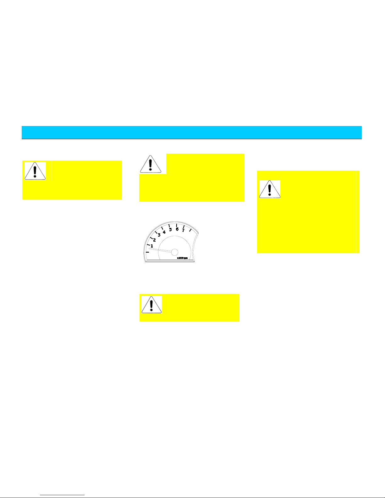
Notice during Run in Period
For the driving of vehicles with engine
tachometer, the allowed short period top
engine speed is 6,000 rpm. During the
manual gearshift, make sure to shift to the
next high gear when the engine tachometer
indicator reached red indication area at the
latest.
Avoid the running of engine at
unnecessary high speed. The
earliest shift to high gear will
help save the fuel, reduce the
working noise as well as diminish the
environmental pollution.
The engine speed should not be excessive
low during driving. Shift to proper gear at
reasonable time.
When at cold condition, do not run the
engine at top speed no matter at neutral
gear or any other drive gear.
The new tires don’t have best adhesion at
the beginning of use; therefore, the tires
also need run in. The vehicle speed should
be relative low during first 100 km driving
and the driving should be extremely
careful.
The new brake friction lining also needs
run in, since the brake doesn't have ideal
friction force during first 200 km driving.
During this period the brake effects are a
little poor, therefore the pressure on brake
pedal may be reasonably increased. Such
condition also applies to the each time
when replaced with new friction lining.
When the new vehicle traveled for 800km,
the wheel nuts must be re-tightened to the
specified torque. Please refer to the
chapter “Specification and Parameters” of
this manual for correct torque values. Also,
if the wheel has been replaced or the
wheel nuts have been loosened, then the
wheel nuts should be re-tightened in
accordance with the specified torque after
traveled for 800km.
“One-To-One” Service
In order to provide you with better service
and vehicle use, the dealer of Chery
Company will appoint one service counsel
to serve you at the purchase of your
vehicle. In case of any problems during
your vehicle use, you may contact your
service counsel, who will provide you
with best services.
Page 8
Summary
8
Vehicle Delivery Inspection Evidence
This is to certify that this vehicle has
completed the vehicle delivery inspection
defined by Chery Automobile Co., Ltd. and its
quality met with the technical specification of
Chery Automobile Co., Ltd.
Vehicle Delivery Date:
Dealer Stamp:
Vehicle Owner Name (Unit) Responsible Service Station Name
—————————————————— —————————————————————
—————————————————— —————————————————————
Address
————————————— Responsible————————————
————————————————————
Tel:————————————————— Te l: —————————————————
Page 9
Summary
9
Vehicle information
Vehicle delivery
Dealer stamp
Model
Body VIN No:
Page 10
Summary
10
Chery Vehicle Sale & Delivery Sheet
Category No. Item
Whether inspected OK and
clearly explained
1 Engine.
Yes □ No □
2 Engine oil, brake liquid, steering liquid, coolant, battery liquid, windscreen
cleaning liquid.
Yes □ No □
3 VIN number, engine serial number, nameplate and other identifications.
Yes □ No □
4 Entire vehicle locks.
Yes □ No □
5 Entire vehicle lamps including head lamp, turn lamp, fog lamp, combined
lamp, compartment lamp, brake lamp, backup lamp, tail lamp, reading lamp,
and instrument lamp.
Yes □ No □
6 Windscreen glass and body paint.
Yes □ No □
7 Speedometer, engine tachometer, odometer.
Yes □ No □
8 Hub cap, spare tire, vehicle attached tools and entire vehicle operation manual.
Yes □ No □
9 Safety belt, seat, cigarette lighter, A/C switch and vent, glove box and sun
visor.
Yes □ No □
Entire
Ve h i cl e
Performance
10 Glass lifter, rear view mirror, wiper, washer, horn, radio.
Yes □ No □
Page 11

Summary
11
1 93# gasoline fuel.
Yes □ No □
2 Normal operation during run in.
Yes □ No □
3 Operation of entire vehicle lamps.
Yes □ No □
4 Meaning of alarm indicators.
Yes □ No □
5 Correct maintenance period and mileage.
Yes □ No □
6 Vehicle maintenance items in winter and summer.
Yes □ No □
7 Correct understanding of cooling system/coolant usage.
Yes □ No □
8 Correct operation of A/C.
Yes □ No □
9 Notices for vehicle start.
Yes □ No □
Operation
Knowledge
10 Correct operation of audio equipment.
Yes □ No □
Salesman Signature: Date: User Signature: Date:
Page 12

Summary
12
“One-To-One” Counseling Service Card
(Service S tation)
User Name: Vehicle Purchase Date:
Sales Agency: Model:
Vehicle VIN Number:
Following items should be validated by the user:
I. Related items confirmation at vehicle delivery (“√” for Yes as
“×” for No)
□ Basic vehicle operation method has been introduced and the
onsite delivery inspection is certified OK.
□ Quality warranty policy has been introduced.
□ Vehicle driving notice has been introduced.
□ The importance of vehicle periodical maintenance and
maintenance period/mileage has been introduced.
□ The importance of vehicle maintenance/repair at Chery
authorized service station has been noted.
□ User’s Manual has been handed over and the reading is
reminded.
□ The function and operation method of service hotline of Chery
Company has been noted.
II. “One-To-One” counseling service mode introduction (“√” for
Yes as “×” for No)
□ Contact the service counsel instead of anyone else in case of
any problems or needs.
□ The service counsel appointed by the service station is the
exclusive person to communicate and contact with the user.
□ One user is only served by one service counsel: “One-To-One”
□ User may choose other service counsel when dissatisfied with
current service counsel.
III. Major job introduction of service counsel (“√” for Yes as “×”
for No).
□ Repair maintenance service reception
□ Complaint acceptance
□ Periodical maintenance reminding visits
□ Repair/Maintenance counsel explanation
□ Periodical greeting visits
□ Repair/maintenance reservation acceptance
□ Service activity reminding visits
□ Annual authentication reminding/acceptance
□ Important festival greeting
□ Other activities of user’s needs
IV. Establishment of “One-To-One” counseling service
relationship.
Service Counsel Card
User Signature/Date: Service Counsel Signature/Date
Form one--- Saved by customer
Page 13

Summary
13
“One-To-One” Counseling Service Card
(Customer)
User Name: Vehicle Purchase Date:
Sales Agency: Model:
Vehicle VIN Number:
Following items should be validated by the user:
V. Related items confirmation at vehicle delivery (“√” for Yes as
“×” for No)
□ Basic vehicle operation method has been introduced and the
onsite delivery inspection is certified OK.
□ Quality warranty policy has been introduced.
□ Vehicle driving notice has been introduced.
□ The importance of vehicle periodical maintenance and
maintenance period/mileage has been introduced.
□ The importance of vehicle maintenance/repair at Chery
authorized service station has been noted.
□ User’s Manual has been handed over and the reading is
reminded.
□ The function and operation method of service hotline of Chery
Company has been noted.
VI. “One-To-One” counseling service mode introduction (“√” for
Yes as “×” for No)
□ Contact the service counsel instead of anyone else in case of
any problems or needs.
□ The service counsel appointed by the service station is the
exclusive person to communicate and contact with the user.
□ One user is only served by one service counsel: “One-To-One”
□ User may choose other service counsel when dissatisfied with
current service counsel.
VII. Major job introduction of service counsel (“√” for Yes as “×”
for No).
□ Repair maintenance service reception
□ Complaint acceptance
□ Periodical maintenance reminding visits
□ Repair/Maintenance counsel explanation
□ Periodical greeting visits
□ Repair/maintenance reservation acceptance
□ Service activity reminding visits
□ Annual authentication reminding/acceptance
□ Important festival greeting
□ Other activities of user’s needs
VIII. Establishment of “One-To-One” counseling service
relationship.
Service Counsel Card
User Signature/Date: Service Counsel Signature/Date
Form one--- Saved by customer
Page 14

Page 15
Summary
15
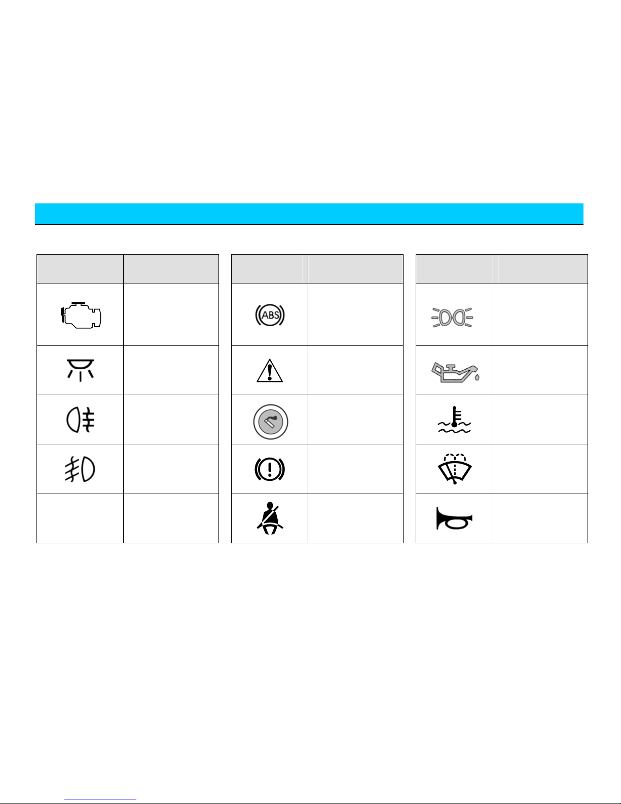
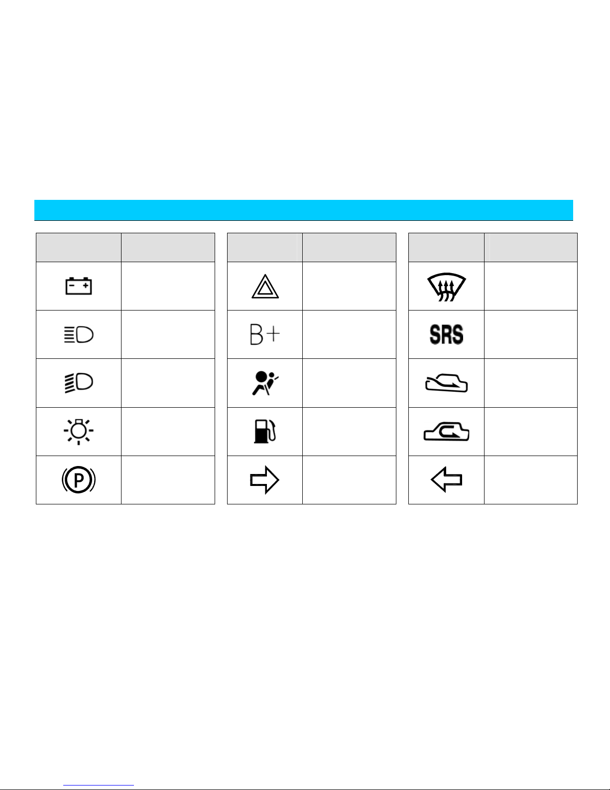
Common Vehicle Symbol Instruction
Symbol Definition Symbol Definition Symbol Definition
Engine
self-examination
trouble light
Anti-lock brake
system
Position lamp
Interior lamp switch
indicator
Safety warning
Engine oil pressure
alarm lamp
Rear fog light
Cigarette lighter
Coolant temperature
overheating alarm
(red indicator)
Front fog light
Brake system trouble
alarm lamp
Windscreen cleaning
A/C
A/C system
Fasten the safety belt
Horn
Page 16
Summary
16
Symbol Definition Symbol Definition Symbol Definition
Battery
Danger flash alarm
lamp
Windscreen
defrosting
High beam lamp
Power + pole
Air bag identification
Low beam lamp
Air bag trouble
indicator
External air
circulation
Head lamp switch
Low fuel level alarm
indicator
Internal air
circulation
Parking brake
indicator
Right turn indicator
Left turn indicator
Page 17

Driving
17
Chapter 2 Driving
Page 18

Driving
18
Driving
Start
Preparation before Start
The engine start is controlled by the
engine electrical control system.
Do not step on the accelerator before start
and during start when starting the
electrical injection engine. The accelerator
should be used only when having difficult
start. Please refer to the section “Engine
Start” for the details of vehicle start.
The long period high speed
idling running of the engine
will result in the overheating
of the engine and the exhaust system,
which may result in the danger of fire
or other damages. Therefore, do not
park, idling run or driving on the
ground covered with dry grass and
other dry coverings. The exhaust
system will increase the temperature
of the engine compartment and the
exhaust pipe that may cause fire.
Do not start the vehicle in
the closed garage or other
closed locations since the
vehicle exhaust gas is poisonous.
Make sure to open the garage gate
before the engine start. Refer to the
section “Caution of Vehicle Exhaust
Fume” for details.
Safety Notice
The idle speed of the engine is controlled
by the electrical control system. The idle
speed at engine start is quite high to help
increase the engine temperature. The idle
speed should reduce automatically when
the engine temperature is increased. Please
deliver your vehicle to the Chery
authorized service station for overhaul if
the idle speed can’t reduce automatically.
Do not run the engine at the speed higher
than specified idle speed for more than 10
min.
Before Vehicle Start
1. Make sure all passengers are
fastened with safety belt. Please
refer to the chapter "Seat and Safety
Protection” for the details of safety
belt and its correct operation
method.
2. Make sure the front head lamp and
other electrical fittings are turned
off.
3. Make sure to lift up the handbrake.
4. Make sure that the gear selector
lever is at neutral gear or parking
gear.
5. Switch the ignition switch to (2), but
not to (3).
If the rotation of the key needs great effort,
it may rotate the steering around, till the
key can rotate freely. The occurrence of
such condition may have following
causes:
y Deflection of front wheel.
y The front wheel touched with the
road curb.
y The steering wheel is rotated during
get-on and get-off (self-lock of the
steering wheel).
6. At the same time when the ignition
key is turned on, make sure that the
dashboard alarm lamp lights shortly.
If not, then it needs to deliver your
vehicle to the Chery authorized
service station for overhaul.
If the driver safety belt is fastened
before turning on the ignition key, then
the safety belt alarm lamp won’t light.
Page 19
Driving
19
Engine Start
1. Rotate the ignition switch to the 3
position but not step down the
accelerator, release the key after the
engine start and the key will return
to the 2 position.
2. If the temperature is higher than -12
℃, then the engine should not be
started within 5s during the first start.
Instead, it should rotate the key to
the OFF position and wait for 10s
before retry.
3. If the temperature is lower than -12
℃, then the engine should not be
started within 15s during the first
start. Instead, it should rotate the key
to the OFF position and wait for 10s
before retry. If the two consecutive
starts all fail, then step down the
accelerator to the end and hold
before rotating the key to the 3
position. After the engine start,
release the key and release the
accelerator pedal slowly following
the increasing of the engine speed.
4. After the engine start, run at idle
speed for several seconds, step down
the clutch, shift to the drive gear,
release the handbrake and prepare
the driving.
5. The normal environment
temperature condition of the engine
start is -25 ~40 (it may present ℃℃
other abnormal conditions when the
environment temperate is out of such
scope).
Caution of Vehicle
Exhaust Fume
In despite of without colour or smell, the
vehicle exhaust fume contains the carbon
monoxide, of which the danger must be
cautioned. The certain contents in the
engine exhaust gas and the certain
chemicals contained or emitted by certain
vehicle components may result in the
cancer, the defect of the new born or other
damage of the genital system.
If you smell the fume
peculiar smell within the
vehicle, please deliver
your vehicle to the Chery
authorized service station for
overhaul immediately. Do not
continue to drive. The exhaust fume
is one poisonous substance that
may endanger the life.
The exhaust system and the vehicle
ventilation system should be checked
under following conditions:
y When the vehicle is lifted for
overhaul.
y When the sound of exhaust system is
changed.
y When the vehicle is damaged due to
the collision.
Ventilation Notice
When the vehicle is parked in the open
field for long period idle or when the
persons rest in the vehicle, the window
should be opened for at lease 2.5cm. Or
open the A/C system ventilation function
to let the fresh air into the vehicle.
Vent
Page 20
Driving
20
Clean the snow, leaf fall
or other foreign articles
blocked in the air inlet so
as to improve the vehicle ventilation
capability.
Engine Control System
Self-adaptive Function
If the battery cable is once removed from
the battery before refit, then the vehicle
may present some abnormal evidences
during the initial period of the driving.
This is the engine control system is
re-learning to adapt to the engine, which
belongs to normal condition.
Vehicle Speed Limit
According to Karry vehicle working
conditions, we offer a max. vehicle speed
limit and we adding the following function
for EFI:
When the vehicle speed reaches 135km/h,
the fuel supply is cut off automatic to limit
the speed. When the vehicle speed
decreases to 120km/h,the engine resumes
fuel supply.
It’s recommended that you
reduce the accelerator
actively when the speed is
close to 135km/h lest the vehicle fuel
supply is cut off and resumed again and
again, causing higher exhaust
temperature.
Engine stall
Release the accelerator pedal. Wait the
engine to lower to idle speed and then turn
off the ignition switch.
Please do not step down
the accelerator pedal
before turning off the
engine.
After long period high speed driving, do
not turn off the engine immediately after
parking. Run the engine at the speed
higher than idle speed for two more
minutes so as to lower the engine
temperature gradually.
Turn off the ignition switch, the
temperature will still be
very high after the turn-off
of the engine and the
radiator electrical cooling fan will
still keep running. Even the cooling
fan stops running, it may run
suddenly again due to excessive high
temperature. Therefore, cautions
should be taken when working near
the engine so as to avoid the
scalding.
Page 21
Driving
21
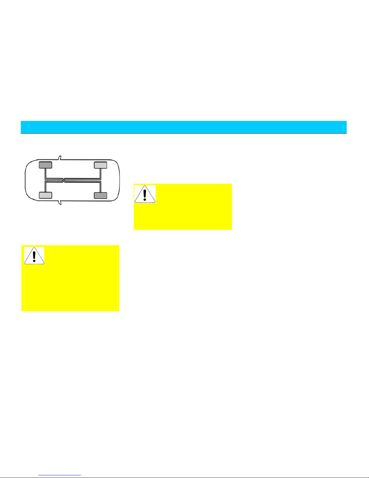
Brake
Dual-Circuit Brake System
Your vehicle is equipped with dual-corner
dual-circuit brake system. The remaining
circuit will still keep effective operation
even if one circuit has fault.
In case of the failure of
one brake circuit, it will
needs more force to step
down the brake pedal and the stop
distance will be lengthened. In case
of the occurrence of such condition,
please deliver your vehicle to the
Chery authorized service station for
overhaul before you continue your
journey.
Brake Liquid
If the brake system alarm lamp doesn’t
turn off upon the release of the handbrake,
it indicates that the brake system has
trouble or the brake liquid level is too low.
The brake liquid level should be checked
periodically in accordance with the
requirements.
Please refill with brake
liquid immediately to
maintain the liquid level at
MAX marking and deliver your
vehicle to the Chery authorized
service station for the checking of
the brake system.
Operation Instruction of
Brake System
It’s quite normal if the brake system issues
noise occasionally. The long period
grinding or screaming noise between the
metal and the metal may indicate that the
brake disc was severely worn out and
should be replaced. At that time, please
deliver your vehicle to the Chery
authorized service station for overhaul.
If there is consecutive shake or shock
transmitted to the steering wheel during
braking, please deliver your vehicle to
Chery authorized service station for
overhaul immediately.
The new brake lining can achieve best
brake effects only after run in. The brake
effects may be slightly lowered within the
initial 200 km. Under such condition, the
brake effects can be compensated by
enhancing the proper force on the pedal.
This essential point also applies to the new
brake lining after replacement.
The worn-out status of the brake lining
depends on the working condition and
driving method to large extent. For the
vehicles mainly for city transportation, the
working condition of the brake lining is
relatively poor due to the frequent start
and stop. Therefore, make sure to deliver
your vehicle to the Chery authorized
service station for the checking of brake
lining thickness or the replacement of
brake lining in accordance with the
maintenance mileage specified in the
Maintenance.
For downward slope driving, it should
shift to low gear at proper time so as to
sufficiently take advantage of the brake
effects of the engine and reduce the load
of brake system. At that moment, the
brake pedal should be stepped down all
the time even the braking is required.
The moisture brake disc will reduce the
Page 22
Driving
22
All pedals should be
stepped down to the
end and should fully
brake efficiency. After paddling, heavy
rain or car wash, it should step down the
brake pedal slightly to generate friction
heat between the brake disc and the brake
lining so as to evaporate the water and
resume brake effects.
If the vehicle is equipped with front
spoiler, it should ensure the
free airflow to the front
brake; otherwise the brake
system may overheats due to poor heat
radiation to reduce the brake effects.
Brake Booster
If the brake booster can’t function because
the vehicle is trailed or it’s due to its own
fault, then it needs to enhance the stepping
force to compensate the boosting effects of
the booster.
Therefore, it’s preferable not to place the
foot cushion or other covering on the floor
around the pedal. If really needed, then
make sure that the placement of foot
cushion won’t obstruct the pedal
movement without any sliding.
The brake booster is subject to the
control of engine vacuum booster. This
device will act only when the
engine is running. Therefore,
do not turn off the engine for
sliding when driving on downward
slopes.
Anti-lock Brake System (ABS)
( )
The anti-lock brake system can avoid the
lock of the wheels that can keep the
steering performance of the vehicle even
under emergent braking so as to escape the
obstacles.
Reaction of ABS
The anti-lock brake system will not effect
under normal brake period and will effect
only when the wheels are almost locked.
During braking, the pulse movement of
the brake pedal together with the noise
indicates that the ABS is under working.
Such pulse movement and noise are
normal. At such moment, do not release
the pedal.
Braking Taki ng Advantage of ABS
The consecutive stepping down of the
brake pedal with full force under emergent
condition will actuate the antilock brake
system immediately to keep the control of
steering. If with enough space, you still
can escape the obstacles.
It’s recommended that you should get
familiar with this brake technology firstly;
however, any unnecessary adventures
should be avoided.
Though ABS can ensure
the best brake effects,, the
stop distance will have
great difference depending on the
road conditions. The ABS can’t
always make sure to reduce the
braking distance, such as on sand or
snow ground, the braking distance
of the vehicle with ABS may be
much longer than the one of the
vehicle without ABS. Also, taking
Page 23
Driving
23
advantage of ABS can’t eliminate
the dangers arising from the
excessive short distance with
foregoing vehicle, paddling,
excessive fast turn or poor road as
well as avoid the accidents arising
from the careless and incorrect
driving. Please drive carefully and
decelerate the driving at turns.
ABS Self-Examination
The ABS will conduct the
self-examination after the vehicle start.
The mechanical noise can be heard during
this period, which is quite normal.
The lighting of ABS alarm
lamp during driving
indicates the fault in the
ABS system, at that moment the
mechanical system can function the
normal brake effects, which should
be noticed during driving. Please
contact with Chery authorized
service station timely to repair the
ABS system.
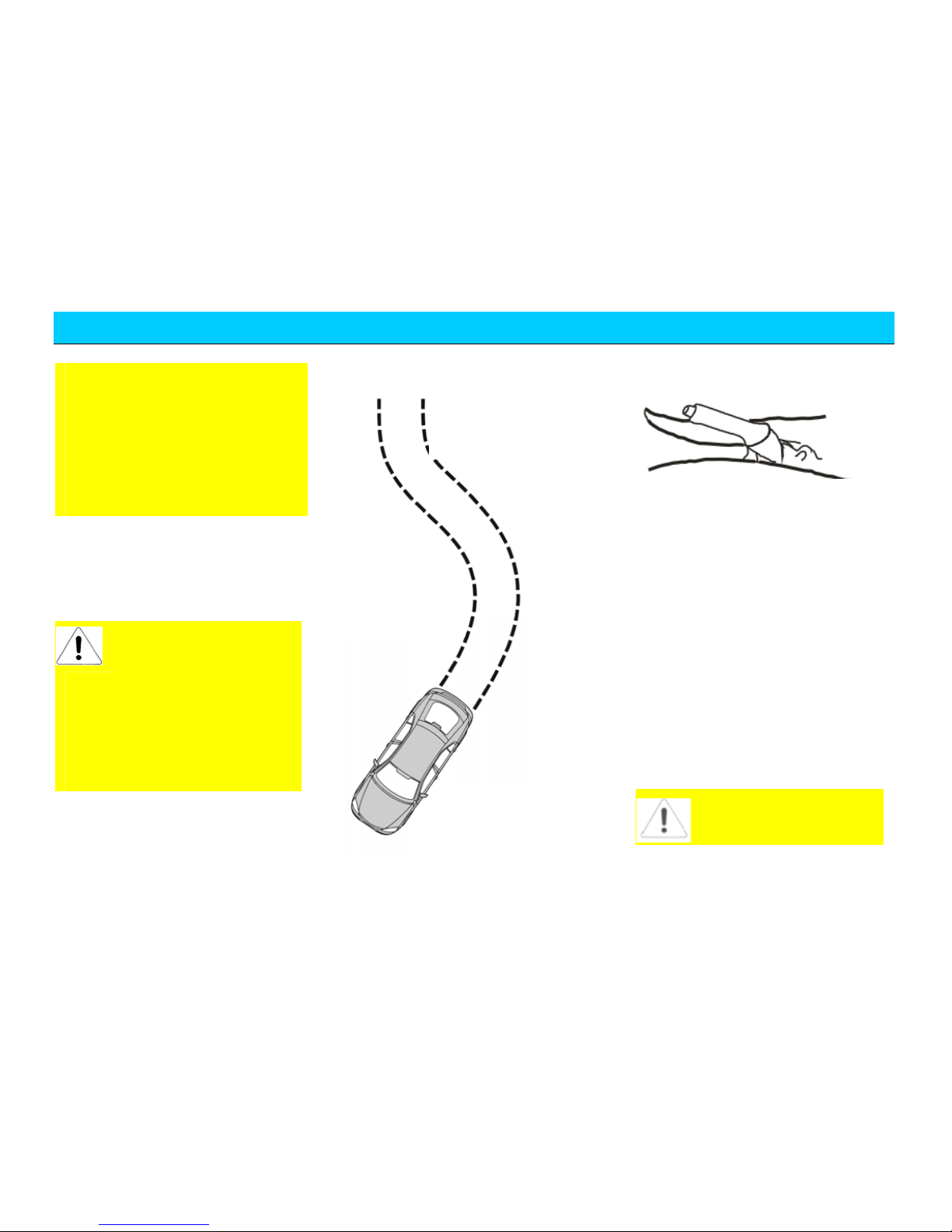
Figure of ABS braking
Handbrake
Pull up the handbrake handle after parking
so as to avoid the humping due to
temporary carelessness.
The parking brake lamp will light when
applied with handbrake under the
condition that the ignition switch is turned
on.
Pull up the handbrake lever when using
handbrake.
When releasing the handbrake, pull up the
handbrake lever slightly, push down the
release button at the end of the handle and
push downward.
The handbrake is applied on the rear
wheels. It can step down the brake pedal at
the same time the handbrake is pulled up
so that it can pull up the handbrake much
easier.
Make sure to pull up the
handbrake handle before
leaving the vehicle.
Important principle of
taking advantage o
f
ABS for braking
1. Step down brake
p
edal and hold wit
h
full efforts.
2. Rotate the steering
wheel to round the
obstacle. You can
maintain the turn control
capability no mater how
violent the braking is.
Page 24
Driving
24
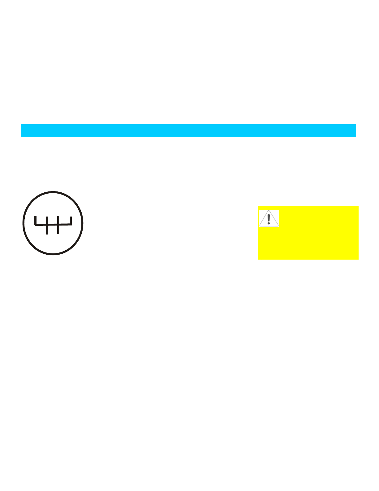
Operation of Manual
Transmission
Karry manual transmission has five
driving positions and one reverse position.
Please see the following figure:
R
1
3
5
2
4
Use/Operation Method and Notices:
y During gearshift, fully step down the
clutch pedal and move shift lever to
the chosen position, and shift it to
the position by little force. If it
doesn’t shift successfully, shift to the
position by stepping down the clutch
pedal again. Release the driver from
the engine torque and then operate
the gearshift lever for gearshift
rapidly.
y The low speed gear should be used
for downward slopes and turns. The
slide with disengaged clutch is not
allowed.
y When shifting the transmission from
low gear to high gear, do not
conduct gear skip operation;
otherwise the service life of the
synchronizer will be affected.
y The forced gearshift by means of
synchronizer to start the engine
under neutral gear and engine stall
status is strictly prohibited;
otherwise the service life of the
synchronizer will be affected.
y The flap method (namely the
operation method of one pulling and
one releasing) is strictly prohibited
during gearshift. Please always hold
the transmission lever with hand so
as to greatly reduce the slide and
friction time and the worn-out of the
synchronizer lock ring.
y After shifting, do not leave your
hand on the gear selector lever
during driving; otherwise it will
result in the early worn-out of the
gearshift fork.
y In case of the detection of any
abnormal evidences such as
abnormal noise of the transmission
or the obvious heavier operation
during use, please stop the vehicle
for inspection immediately and
continue the driving once the trouble
is resolved.
y During normal driving, don’t put
feet on the clutch pedal to avoid
unnecessary clutch wear.
S teering
In order to avoid the damage of power
steering system, please read the following
items carefully:
y The time when rotating the steering
wheel to the end (to left dead point
and right dead point) should not
exceed 10 s during engine running.
y When the power steering liquid in
the power steering liquid reservoir is
lower than MIN mark, please refill
Shifting gear in reverse
direction is prohibited while
driving, or else the
transmission will be damage. Chery
Automobile Co., Ltd. will not be
liable for any damages arising from
improper operation.
Page 25
Driving
25
with power steering liquid
immediately. Do not drive the vehicle
before refill.
In case of trouble of power steering
system or the turn-off of the engine, the
vehicle will lose the steering boosting. You
still can rotate the steering wheel,
provided with great strength.
In case of vehicle deflection or tremble
during the driving, please check the
following items:
y Whether the tire pressure is
insufficient.
y Whether the tire is worn evenly.
y Whether the suspension components
is loosened or worn out.
y Whether the steering components is
loosened or worn out.
y Whether the wheel alignment is
correct.
Paddling
If it’s must to paddle during journey, make
sure to drive slowly and carefully,
especially when having no knowledge of
the water conditions. Do not drive forward
further if the water can submerge the
wheel hub.
During paddling, the traction force and the
brake performance of the vehicle will be
lowered and the vehicle will have the
danger of stall.
In case of the water ingress into the intake
pipe of the engine, it will cause the serious
damage of the engine. The deeper
paddling will result in the water ingress
into the transmission through the
transmission air vent, which will result in
the damage of the transmission.
After paddling, make sure to drive slowly
and step down the brake pedal slightly for
several times to remove the water from the
brake. The water on the brake will lower
the brake performance.
Three-Way Catalytic
Converter
The catalytic converter will help reduce
the pollution of exhaust gas.
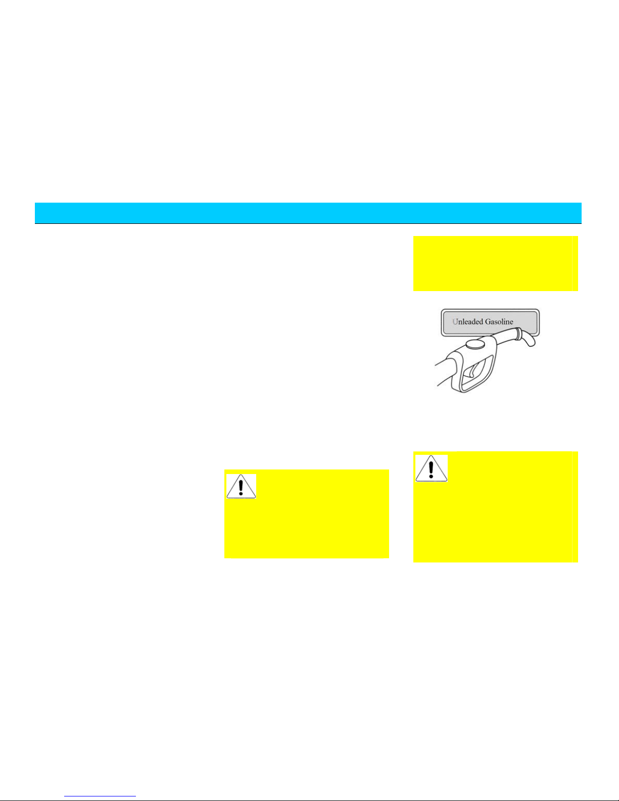
Make sure to use unleaded
fuel. The leaded fuel will
result in the permanent
damage of the catalytic converter
and the oxygen sensor. Chery
Automobile Co., Ltd. will not be
liable for any damages arising from
the use of leaded fuel. Such damages
are excluded from the warranty
scope. If you refill with leaded fuel
accidentally, please contact with the
nearest Chery authorized service
station.
The vehicles with gasoline engine are
equipped with narrow refill opening that
only accommodates the unleaded gasoline
pump refuelling gun nozzle.
During the running of the
gasoline engine, it’s
absolutely not allowable to
pull out the high voltage line of the
ignition coil. Check if the engine
functions normally by means of
cylinder stall method or observe the
jump spark condition of the spark
plug; otherwise the three-way
catalytic converter will be damaged.
Page 26
Driving
26
Notice:
The three-way catalytic converter will be
getting very hot if the engine is under
continuous running, therefore, notice to
wear the protective glove during repair so
as to avoid the scalding.
Drive the Vehicle Equipped
with a Catalytic Converter
In case of the evidence of
poor engine ignition or the
lowered performance
during driving, please drive at low
speed to the nearest Chery
authorized service station. Do not
drive at large accelerator.
Please avoid the condition that will result
in the ingress of the un-combusted or
partial un-combusted fuels into the
catalytic converter, especially when the
engine is at high temperature.
The following conditions should
be avoided:
y Run out of fuel.
y Unnecessary long period start of the
engine.
y Run the engine under the condition
that one spark plug cable terminal is
removed.
y Start the vehicle with the engine still
at working temperature by means of
pulling or hauling.
y Turn off the ignition switch during
driving.
Parking
Do not park, idle or drive the vehicle on
the dry leaves or grass. Even the engine is
turned off, the exhaust within short period
will continue the radiation of equivalent
heat, and therefore, it still has potential
fire danger.
Make sure to turn off the ignition switch
before leaving the vehicle. Do not run the
engine when no one is in the vehicle. The
negligence of this point may result in the
accident movement of the vehicle, which
will result in the body injury or property
damage.
Chassis Protection
Your vehicle is equipped with heat
insulation plate. Do not apply the paint on
the body of heat insulation plate, exhaust
pipe or catalytic converter or the
surrounding areas. Do not disassemble the
heat insulation plate.
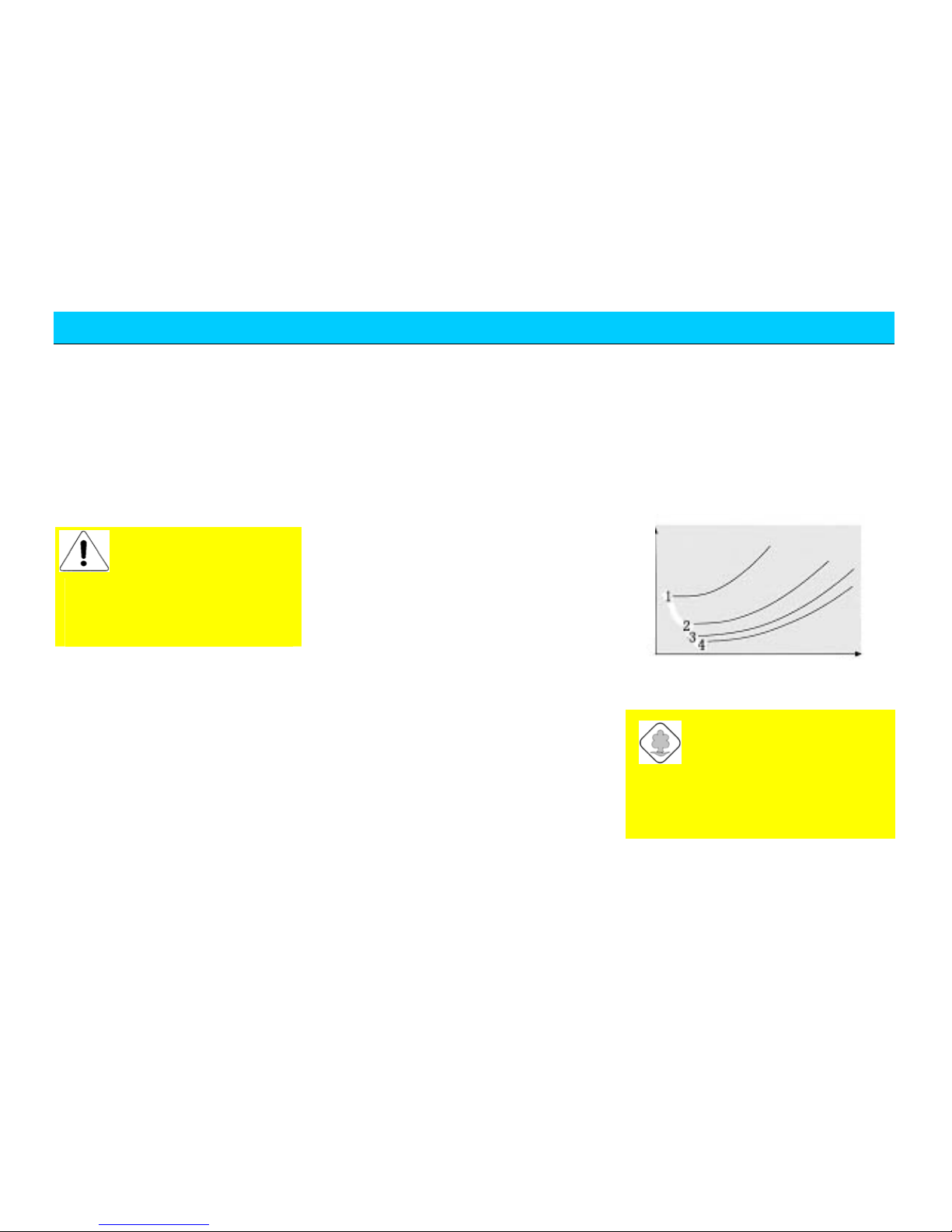
Fuel Consumption
The fuel consumption is
influenced by the following
factors:
Selection of Vehicle Speed or Gear
The above figure illustrates
how the fuel consumption is
influenced by the selection of
vehicle speed and gear. Maintaining at
low gear to improve the acceleration
performance will result in the obvious
higher fuel consumption.
Fuel consumption
Vehicle speed
Page 27

Driving
27
It’s recommended to turn off
the engine during traffic jam
or long period waiting such as
red light
Stroke Distance/Engine
Temperature
The frequent cold vehicle start and the
short distance journeys will result in the
obvious increasing of the fuel
consumption.
Traffic and Road Condition
The crowded traffic, upward slopes, multi
curved routines and rough roads will cause
detrimental influence on the fuel
consumption.
Good Driving Habits
The prediction of danger and keeping safe
driving distance with foregoing vehicle
will not only reduce the fuel consumption
but also reduce the wearing and noise of
the brake.
The 3min engine idle is equivalent to
driving for 1km.
Vehicle Load Status
The increasing of vehicle load will result
in the higher fuel consumption.
Vehicle Technical S tatus
The low tire pressure or improper engine
and vehicle maintenance also will result in
higher fuel consumption.
Essentials for Fuel- Saving
Driving and Environmental
Protection:
y Fuel-saving driving, and use
supplementary electrical loads only
when needed.
y Start without the heating of the
vehicle.
y Use the accelerator smoothly.
y Shift to next higher gear as soon as
possible so as to achieve lower
engine speed.
y Prediction of traffic condition.
y Turn off A/C and rear windscreen
heating immediately whenever
unnecessary.
y Check/adjust the tire pressure
periodically.
y Conduct vehicle maintenance
periodically, preferable conducted by
Chery authorized service station.
Radiator Fan
The radiator fan is an electrical fan with
the working condition controlled by the
engine ECU. This switch will
automatically turn on the fan circuit when
the coolant or the engine compartment
reached certain temperature.
After stopping the vehicle
and the engine, the radiator
fan will continue running
for certain period since the engine is
still under hot condition and will
stop running when the engine is
cooled to certain temperature. Even
though, the fan may still start
suddenly in case of the sudden
temperature increasing of the engine
compartment due to the influence of
the ambient environmental
temperature (sunshine exposure or
high temperature region). Therefore,
cautions should be taken when
operating in the engine
compartment so as to avoid the
accident.
Instruction:
If the fan isn’t running when the coolant
temperature reached the fan start
temperature, then check the fan fuse for
burn-out. Replace the fuse if necessary.
Page 28

Driving
28
The fan speed is independent of the engine
speed and the gearshift to low gear will
not promote the cooling effects of the fan.
Therefore, it’s unnecessary to shift to low
gear provided that the engine runs
smoothly and the vehicle speed has no
obvious reduction on upward slopes.
Chapter 3
Page 29

Introduction of Vehicle Functions & Instruction of Designation
29
Introduction of Vehicle Functions
& Instruction of Designation
Page 30
I. Introduction of Vehicle
Functions
Steering wheel lock/
ignition sw
itch
Explanation for lock-hole positions of
steering wheel:
Position 1- Turn off the ignition switch
and lock the steering wheel. Please turn
the steering wheel until a click of steering
wheel locked is heard after pulling off the
key in order to lock the wheel. Radio and
horn shall not work in the position.
DO NOT pull out the key
before the vehicle parking
completely to avoid locking
the steering wheel unconsciously.
Position 2- Switch on the ignition circuit
If the key cannot be or difficult turned to
the position, it may slightly turn the
steering wheel and then the locking
mechanism of steering wheel will be
unlocked.
Position 3 – start the engine
When the lock hole is at the position, the
headlamps and electrical equipment that
consume more power will be switched off
fully.
There is an anti-restart device in the
ignition switch. Once the engine starts, the
device may prevent the engine mis-start,
so that it can avoid the damage from
engine and flywheel of engine. If the
startup is not successful, the ignition key
must be turned to Position 1 and then
Position 2 before restart
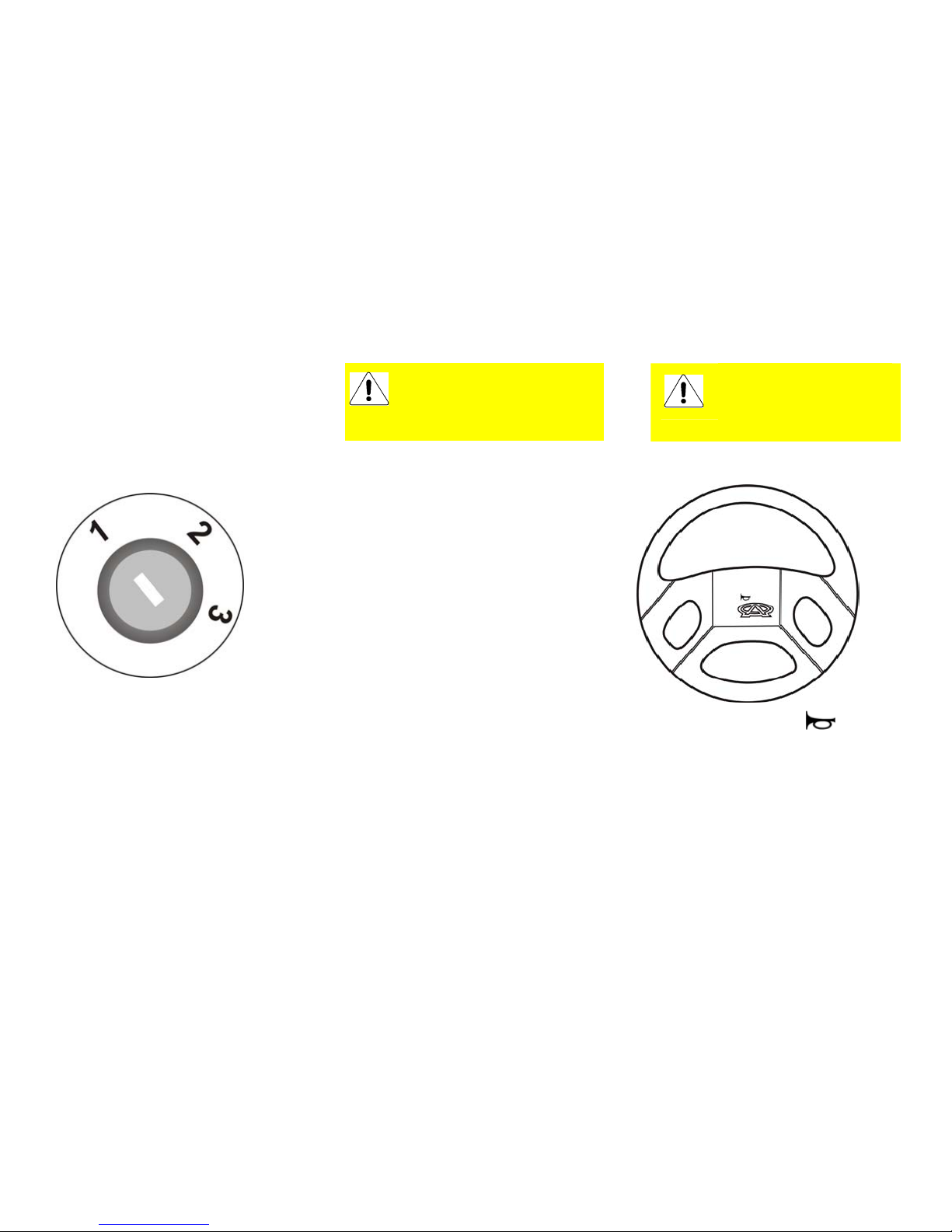
Horn
Press down the button on the
steering wheel to operate the horn. The
horn can be operated only under the case
of ignition switch on.
The key must be loosened
once the engine is started.
DO NOT remain the key at
Position 3 for a long time.
Page 31

Introduction of Vehicle Functions & Instruction of Designation
31
Windscreen wiper and
cleaning system
The wiper is only available with the
ignition switch on. There are four
positions and Position 1 for no use.
Intermittent wiping
Move the control lever one position
downward to Position 2 from Position 1.
The wiper controller will automatically act
once every a certain time.
Normal wiping
Move the control lever one position
upward to Position 3 from Position 1.
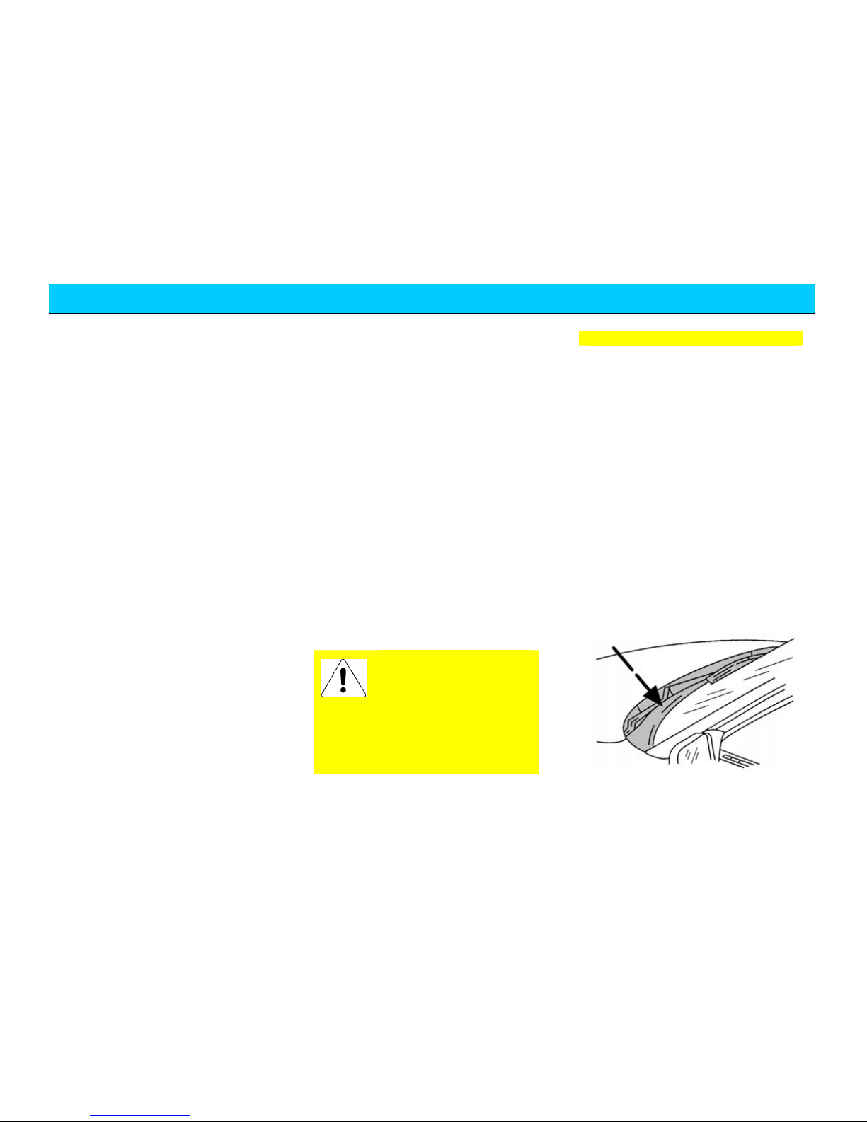
It must check the wiper
blade whether frozen on
the windscreen before use
in cold season. The wiper blade
must be unfrozen if it is frozen on
the windscreen. Otherwise, the
wiper motor will be damaged.
Operating the wiper with obstacles
such as snow may result the wiper
motor damaged as well.
Obstacles shall be removed before
operating the wiper.
DO NOT operate the wiper on a
dry windscreen, otherwise it may
scratch the glass and make
permanent damage on the wiper
blade.
Page 32

Introduction of Vehicle Functions & Instruction of Designation
32
The wiper controller will act continuously
with even speed.
High speed wiping
Move the control lever two positions
upward to Position 4 from Position 1.
The wiper controller will act continuously
with the highest speed.
Water spray switch
Pull the switch handle toward to the
steering wheel and hold in the position, the
cleaning fluid will spray out from the
injection nozzle in front of the windscreen
and the wiper is acting synchronously.
Water spray will stop after releasing the
handle, but the wiper still acts several
times.
Interior rearview mirror
To reduce the glare during night driving, it
may push the adjusting rod backward to
adjust the angle of rearview mirror.
Sun visor
The sun visor may be turned to side
window by unfastening the fasteners.
Articles such as driving license and gate
toll tickets, etc. may be kept in the back of
the sun visor.
Water spray time shall not
exceed 10s once. DO NOT
operate the switch in case
of no cleaning fluid in the
reservoir. Otherwise it may result
the spray motor damaged.
Night driving
Daytime driving
Page 33

Introduction of Vehicle Functions & Instruction of Designation
33
Electrical window control
switch (
)
The electrical window control button of
the vehicle is in the lower part of the A/C
system panel of the instrument panel.
Electrical exterior rearview
mirror
The electrical rearview mirror may be
adjusted by the adjusting switch on the
lower part of A/C panel of instrument
panel. The adjusting switch only works
when the ignition switch is on at Position
2.
Turn the adjusting switch
counterclockwise in place to adjust the left
exterior rearview mirror; Turn the
adjusting switch clockwise in place to
adjust the right exterior rearview mirror.
When the adjusting switch turns left or
right properly, push the switch leaning to
front, rear, left and right four directions for
adjusting the up, down, left and right
positions of the mirror respectively. Then
turn the switch to the middle position after
the mirror is adjusted well.
The exterior rearview mirror may be
folded inward if necessary such as in
narrow space. The mirror may be opened
until blocked in proper position for
returning to the original position.
The object in the convex
rearview mirror looks like
smaller and further than the
practical one. DO NOT over
estimate the practical distance of the
object.
Left front
Electrical
Right front
electrical
Trim button
Press for Up
Press for down
Middle position
Adjusting
position for left
rearview mirror
Adjusting position
for left rearview
mirror
Page 34

Introduction of Vehicle Functions & Instruction of Designation
34
Ashtray, cigarette lighter
The ashtray is located in front of the gear
handle. Push inward the cover and loosen
the ashtray, it will automatically pop out.
Take out the insert and empty it.
The cigarette lighter is in the right side of
ashtray. Press it inward and wait for
popping out for use. The cigarette lighter
is available even if the ignition switch is
off.
Use of protection net
In order to ensure the safety of passengers
and requirements for loading different
goods, two places are set inside the vehicle
for hanging protection nets.
When loading less goods and the mid seat
is not used, the protection net shall be
hung on the hooks of mid protection net,
and the hooks under the net shall be fixed
well, so that it may ensure the safety of
passengers who are in front seats
maximally and prevent the danger of rear
goods flying forward due to sudden brake.
When loading more goods and the mid
seat is used, the protection net shall be
hung on the hooks of front protection net,
and the hooks under the net shall be fixed
well, so that it may ensure the safety of
passengers who are in front seats
maximally and prevent the danger of rear
goods flying forward due to sudden brake.
Light Control
Please follow related traffic rules while
using the illumination equipment as
below:
Headlamp switch
The headlamp switch is not subject to the
control of ignition key. It can still work in
The cigarette lighter
shall not remain in
inserted state for a long
time to avoid danger. It shall be
taken away if a child stays in the
vehicle alone.
Hooks of front protection net
Hooks of mid protection net
Page 35

Introduction of Vehicle Functions & Instruction of Designation
35
case of the ignition switch off. Press the
left side of headlamp switch button once,
parking lamp/ position lamp, light for
instrument and switches, license lamp and
dipped headlight will be on.
Press the left side of headlamp switch
button twice, the headlamp switch is at
Position 2, and the high beam will be on.
Conversion of high beam/
dipped headlight
Pull the handle toward to the direction of
steering wheel when the headlamp switch
is at Position 2, through the forced point
and it will convert to high beam. When
turn on the high beam, the indicator lamp
for high beam on the instrument panel
will also be on. Pull the handle
toward to the director of steering wheel
once more and return to original position,
it resumes to the dipped headlight.
Flicker of headlamp
If you need to flicker the headlamp during
driving, the handle shall be pulled toward
to the direction of steering wheel at the
forced point, then release the handle and it
will automatically return. Repeat the
action and the headlamp will flicker
continuously.
Front fog lamp switch
Rear fog lamp switch
Front and rear fog lamp switches are at the
left side of instrument panel, beside the A/C
air outlet.
When the headlamp is on at Position1,
press the front fog lamp for turning the
front fog lamp on, but the rear fog lamp
won’t be turned on. It shall turn on the
front fog lamp first and then the rear one.
When the front fog lamp is on, the
indicator lamp in the instrument panel
will light.
The front fog lamp can only be used in
case of visibility is seriously limited such
as fog, snot or rain, etc.
When the rear fog lamp is on, the indicator
lamp in the instrument panel
will
light.
Page 36

Introduction of Vehicle Functions & Instruction of Designation
36
The rear fog lamp has stronger glare, so it
is only allowed to use in very low
visibility.
Turning indicator
The turning indicator can work only after
the ignition switch is started.
Left turning indicator—pull the handle
downward
Right turning indicator—pull the handle
upward
When the turning indicator is on, the
turning indicator lamp on the instrument
panel will flicker.
Lower left button on the
instrument panel
Adjusting button of
instrument illumination
It may adjust the illumination strength
when the headlamp is at Position 1. The
adjusting button is beside the headlamp
switch in the lower left part of instrument
panel.
Front interior ceiling
lamp
Adjusting button
of instrument
illumination
Headlamp switch
Turn the
button
downward to
lighten the
instrument
up
Page 37

Introduction of Vehicle Functions & Instruction of Designation
37
Press the left switch: left light continues
on. The light is off with right press. Press
once more, the light is on with the door
open and off with the door close.
Press the right switch: right light continues
on. The light is off with right press.
When the left switch is at position,
open the door and the compartment lamp
will be on. The lamp will be on
continuously for 15 seconds after the door
is closed for the convenience of
passengers seating. If the key is at ON
position, the compartment lamp will be on
when the door open and off immediately
with the door closed without delay
function.
Rear interior ceiling lamp
Sliding switch at OFF position: the light is
off.
Sliding switch at ON position: the light is
on continuously.
Sliding switch at door control position:
open the door and the compartment lamp
will be on. The lamp will continues on for
15 seconds then off after the door is closed
for the convenience of passengers seating.
Danger flash alarm lamp
switch
The switch is on the panel of combination
switch between the instrument panel and
steering wheel.
It is only used in emergency case for
warning the following vehicles that the
vehicle has faults or danger. Press the
switch to connect/ disconnect the system.
The lamp can still be used with the
ignition switch off.
After the alarm lamp is connected, the
indicator lamp on the switch will flash.
Left and right turning indicators on the
combination switch will flash at the same
time.
Braking lamp
When step on the brake pedal, the braking
lamp will be on. It will be off with the
brake pedal release.
Reversing lamp
When turn on the ignition switch and the
vehicle is at reverse position, the reversing
lamp will be on. The reversing lamp will
be off when the ignition switch is turned
off or changed to other position.
Sound system
Note: If the vehicle is not equipped with
the following sound system, please read
the Instruction Manual for Sound System
supplied with the vehicle carefully.
Page 38

Introduction of Vehicle Functions & Instruction of Designation
38
Panel ( )
Fm1 Fm2 Fm3
AM
LOUD
LO
:
.
15
14
13
10
11
12
9
87
6
5
2
1
3
4
16
Page 39

Instruction of Panel
1. Power supply/ volume/ left, right control button (pull out)
2. Volume adjustment
3. Out key
4. LCD
5. Cover (tape compartment)
6. Backward key
7. Forward key
8. Manual, downward auto-search key
9.Manual, upward auto-search key
10.Auto-save/ saving channel scan key
11.Auto-scan key
12. Loudness control key
13. Frequency modulation/ amplitude modulation wave band
selection key
14.Mono/ stereo control key
15.Presetting key(1-6)
16. Front/rear control key
Page 40

Introduction of Vehicle Functions & Instruction of Designation
40
Operation Method
Basic operation
Tape play
1. Turn the button 1 to the right and
connect with power supply, and
increase the volume properly.
2. Let the tape open side face to the
right and push in the tape
compartment 5 to locking position,
the machine is under play state.
Meanwhile, the display 4 shows
“TAPE” characters and tape direction
indication “▲”“▼”.
3. Adjust the volume button 1 and tone
button 2 to make the volume
moderate and the tone clear and
sweet.
4. The tape can turn over automatically
when it runs to the end. You may
press forward and backward keys 6
and 7 simultaneously for manual turn.
5. In order to select the songs you want
to listen fast, you may press forward
key 7 or backward key 6 for rapid
advance or reverse, then slightly
press another backward key or
forward key once, the machine will
be under play state.
6. The directions “
” or “ ” shown in
the display are the running direction
of tape. Right means clockwise and
left means counterclockwise.
7. If you want to stop play or need to
change the tape, press “out” key 3
and the tape will pop out the
compartment.
Listen to the radio
1. Power switch, volume
control and
volume adjustment are the same as
“Tape Play”.
2. Press the “Frequency modulation/
amplitude modulation selection key”
13, the wave band to be received will
show on the display 4. You may select
one from FM1, FM2, FM3 and AM
depending on your demand.
3. Automatic, automatic tune (channel
selection):
(1)Instantaneously press Key 8 or Key
9 to fulfill manual tune, repeatedly
press the key till the wanted channel is
received.
(2)
Constantly press Key 8 or Key 9 over
0.5 second, the machine shall complete
auto-tune. The tuning is ended after a
channel received. Repeat(1)or(2),
you may receive the program you
wanted.
4. Automatic scan tune:
Instantaneously press SCN Key 11 to
realize auto-scan function, the machine
will automatically scan channels from the
frequency up to down. It will suspend
scanning when a channel is caught. The
channel frequency will flash for 5 seconds
and play the program of the channel. Then,
it will continue to scan the higher
frequency and automatically return when
it reaches the highest frequency. Then it
scans from the lowest frequency to the
highest again.
When you want to listen to a certain
channel, you only need to press SCN key
once as the channel frequency flashing.
The scan will stop at the channel position
immediately. It will resume the auto-scan
Page 41

Introduction of Vehicle Functions & Instruction of Designation
41
if you press SCN key again.
5. The display 4 shows stereo symbol
“ST” when you are receiving stereo signal.
When you want to receive mono signal
program, you only need to press “MO”
key 14. Then the “ST” on the display is off
and the “MO” symbol is on.
Channel frequency memory
Y
ou may use 1-6 memory key of
Presetting Key 15 to pre-save 4×6
channel frequencies under FM1, FM2,
FM3 and AM states respectively.
1. Manual memory
When you have searched a channel by
auto-search, then press one of 1 × 6
memory keys for at least 3 seconds. When
the channel broadcast is from strong to
weak and then strong, the channel
frequency has been saved in the memory
you pressed.
2. Automatic memory
Constantly press AS Key 10 at least 3
seconds at some wave band and the
machine enters in preset auto-selection
and save program; the display 4 shows
“ATP” character, the machine searches
channels from low frequency to high
automatically. It may automatically save 6
channels with stronger frequency from the
initial frequency. The machine may show
every channel frequency in circle after
saving and flash the memory code of
current channel for 5 seconds with the
broadcast of the channel. If you press AS
key 10 once more, the machine will show
the codes in circle. For wave bands FM1,
FM2, FM3 and AM, it can fulfill the
foresaid auto-save function.
Scan of saved channels
In a wav
e band, instantaneously press AS
key 10 once, the display 4 will show
already saved 6 channel frequencies in
turn. For every channel frequency, its
corresponding memory code of channel
address may flash for 5 seconds with the
broadcast of the channel. If you want to
listen to the program of a channel, you
may press the digital key (1-6 key)
corresponding to the memory code of the
channel address, the scan will stop at the
channel position. For wave bands FM1,
FM2, FM3 and AM, it can fulfill the
foreside scan of saved channels.
Other Functions
Loudness control
Press “LOU” key 12 at small volume
for high or low frequency tone
compensation. In the time, the display 4
appears “LOUD” character. Press the key
once more, the loudness does not act and
the “LOUD” character is off.
Front/ rear, left/right control
1. Outer
turn button 16 is used for control
the volume of front and rear speakers.
A. The outer turn button is set at
balanced position as the machine
ex-factory. The volume for front and
rear speakers is the same while
operating the machine.
B. According to your demand, please
turn the outer turn button clockwise
to the maximum position if you
want to turn off the rear speaker.
C. Please turn the outer turn button
counterclockwise to the maximum
position if you want to turn off the
front speaker.
Page 42

Introduction of Vehicle Functions & Instruction of Designation
42
2.Pull out the button 1 for controlling the
volume of left/ right speaker.
A. The inner turn button is set at
balanced position as the machine
ex-factory. The volume for left and
right speakers is the same while
operating the machine.
B. According to your demand, please
turn the inner turn button clockwise
to the maximum position if you
want to turn off the left speaker.
C. Please turn the inner turn button
counterclockwise to the maximum
position if you want to turn off the
right speaker.
D. The turn button shall be pushed to
original position in time after the
volume control of left/right speaker
is adjusted.
3 . The button 16 shall be pushed to
original position and then turned it
while controlling the power switch.
General Maintenance
1. Tape head shall be cleaned by head
cleaning tape or tampon with ethanol
after using one month for ensuring the
sound quality. Once the sound appears
stifling or distortion, the tape head shall
be cleaned in time.
2. Please gently push or take the tape, do
not pull or push it with strong force.
3. The machine is precision appliance,
careful use and maintenance is
required.
Page 43

Introduction of Vehicle Functions & Instruction of Designation
43
A/C System
Ventilation
Outside air enters in the vehicle through
the air inlet in front of the windscreen. It
shall keep the air inlet clean without snow
and leaves for ensuring normal heating,
ventilation and efficient work.
Page 44

Introduction of Vehicle Functions & Instruction of Designation
44
AAir outlet of windscreen
S Side defrost air outlet
S Side defrost air outlet
Air outlet of instrument panel
Air outlet of floor
Page 45

Introduction of Vehicle Functions & Instruction of Designation
45
2
2
3
3. Central vent holes
2
Central vent hole
The adjusted air flows in the vehicle
through two central vent holes. The air
flow direction may be changed through
altering the angle of the grille.
Side vent hole
The adjusted air flows in the vehicle
through two side vent holes.
Defrost/ defog vent hole of
front windscreen
Through the vent hole, cold air and warm
air are guided to the front windscreen to
remove the moisture on the windscreen.
1、前车窗除霜器通风口 2、侧通风口 3、中央通风口
1. Side vent holes
2. Defrost/defog vent holes of front windscreen
1
1
2
Page 46

Introduction of Vehicle Functions & Instruction of Designation
46
Control panel
123
4 5
1. Blower switch 2. Temperature control switch 3. Airflow distribution switch
4. A/C switch 5. Internal circulation switch
Page 47

Introduction of Vehicle Functions & Instruction of Designation
47
Ventilation and warm air
A/C system adjusts the temperature by
mixing cold and warm air, the temperature
may be constant under any speed.
The airflow speed is subject to the blower,
which may be started during driving if
necessary.
Temperature control switch
The temperature control switch can
steplessly adjust the temperature of air
passing through the vent hole. When the
A/C system works, it may turn the switch
leftward to increase the refrigeration
volume or rightward to decrease the
volume.
Turn right – temperature up
Turn left – temperature down
Blower switch
The switch is used for controlling the
speed of blower (total 4 positions), turn
the button to Position “0”, and the blower
is stopped. The airflow speed is adjusted
by the blower. Starting the blower during
driving in order to increase the comfort.
Internal/ external circulation
switch
The switch is used for selecting fresh air
outside or circulating the air inside the
vehicle. It defaults as external circulation
mode without the switch pressed down.
External circulation mode
Outside air enters in the vehicle.
Used for normal ventilation, warm air and
cooling.
Internal circulation mode
Air inside vehicle circulates within the
vehicle. The mode is used in case of dusty
environment, or preventing outside exhaust
gas entering in the vehicle, rapidly cooling
or heating the air inside the vehicle with the
switch is pressed down (the indicator lamp
is on).
Airflow distribution switch
The switch is used for selecting the
direction of airflow.
There are 4 positions for the switch:
Using the internal circulation
mode continuously may
result fuggy inside the vehicle and
window misty, so the mode can be
used in short time only.
Page 48

Introduction of Vehicle Functions & Instruction of Designation
48
Head position
Head and foot position
Foot position
Defrost
“Head” position(
)
The air flows out from central vent holes
and side vent holes.
“Head & foot” position(
)
The air flows out from central vent holes
and vent holes in the bottom of front seats.
“Foot” position( )
The air mainly flows out from the vent
holes in the bottom of front seats.
“Defrost” position(
)
The air flows out from the defrost vent
holes of windscreen and front window.
A/C switch
The switch is used for starting and
stopping A/C compressor.
Start the engine and turn the blower switch
to proper air speed, switch on the A/C
switch for starting the air conditioner. The
indicator lamp is on with the A/C running.
Press the A/C switch button once more,
the A/C system stops.
When the blower switch is at “OFF”
position, the A/C compressor does not
work.
A/C system
Ventilation, warm air and refrigeration
components consist of a control system,
which may provide the highest comfort
under any weather condition.
The refrigeration unit of A/C system cools
the air down and removes moisture and
dust such as pollen, etc.
The A/C system may lead to
the engine overheated with
it working while the vehicle is
climbing a long slope or at traffic
jam. Observe the water
temperature gauge and shut down
the A/C if the engine is overheated.
Page 49

Introduction of Vehicle Functions & Instruction of Designation
49
Max. refrigeration
It shall open the windows for short time to
discharge the inside hot air rapidly when
the vehicle exposes in sunshine for a long
time in hot weather. It shall follow the
steps as below:
1. A/C switch: ON
2. Internal circulation switch: ON(
)
3. Airflow distribution switch: (
)
4. Temperature control switch: turn to the
bottom counterclockwise (blue)
5. Blower switch: at Position 4
Normal refrigeration
Normal refrigeration for long distance
journey and high speed driving shall
follow the steps as below:
1. A/C switch: ON
2. Airflow distribution switch: (
)or
(
)
3. Temperature control switch: turn the
switch to the required position.
4. Blower switch: any position (Position
1-4)
Max. heating
Follow the steps as below:
1. A/C switch: ON
2. Internal circulation switch: ON(
)
3. Airflow distribution switch:(
)
4. Temperature control switch: turn to the
bottom clockwise (red)
5. Blower switch: at Position 4
DO NOT use “force
heating” for a long time to
prevent inside air grimy
and window misty. The internal
circulation switch shall be turned
off if the windows are misty or wet.
“Force heating” is only used for
rapid heating up, and it shall return
to “normal heating” as soon as
possible.
Ventilation
Outside air flows in the vehicle through
central vent holes and side vent holes.
A/C switch: OFF
Internal/ external circulation switch:
external circulation mode
Airflow distribution switch: (
)or
(
)
Temperature control switch: blue
Page 50

Introduction of Vehicle Functions & Instruction of Designation
50
Blower switch: any position (Position 1-4)
Normal heating
Follow the steps as below:
1. A/C switch: OFF
2. Airflow distribution switch: (
)or
(
), if there is moisture on the
windscreen, it shall adjust button
between (
)or( ).
3. Temperature control switch: turn the
switch to the required heating position.
4. Blower switch: any position (Position
1-4)
Defrost
Follow the steps as below:
1. A/C switch: ON
2. Airflow distribution switch: (
)
Temperature control switch: turn to
heating position if necessary
3. Blower switch: at Position 2 or Position
3
Defog
1. A/C switch: ON (press down), working
indicator lamp is on
2. Internal/ external circulation switch:
external circulation mode
3. Airflow distribution switch: (
)
4. Temperature control switch: red
5. Blower switch: proper position
Using detergent to clean
internal surface of window is
an efficient method for
preventing mist. Using absorbent
cotton or soft cloth dipping with the
detergent to wipe the inside of front
and rear windscreens 9 including
window glass at rearview mirror),
then clear up the remaining fiber on
the windscreens with soft dry cloth
after airing.
Operation instruction for cooling
system
If the vehicle is directly under sunshine, the
windows shall be opened before starting
A/C.
Switching on A/C may
increase defrost
efficiency. DO NOT use
or as
refrigeration if the weather is very
wet, which may result temperature
difference between outer air and
windscreen, raise mist on the
internal surface of windscreen and
affect view.
Page 51

Introduction of Vehicle Functions & Instruction of Designation
51
Windows shall be cleaned in rainy days. It
may reduce the temperature inside vehicle by
starting A/C, which is efficient in rainy days
and hot days.
The cooling system may not cool fully due to
frequent parking and slowly driving in a
traffic jam area.
If the A/C system does not work for at least
one month, the system must be started under
engine idling, even if in winter, at least once
each month and running for several minutes,
in order to keep proper lubrication and
airtightness of compressor and extend the
service life of the system.
The A/C compressor does not work with the
blower switch off.
Page 52

Introduction of Vehicle Functions & Instruction of Designation
52
Instrument
Panel
Steering wheel
Horn
Combinatio
n instrument
Sound system
A/C air outlet
Glove box
A/C control panel
Front fog
lamp
Rear fog
lam
p
Window regulator control for four doors( )
Headlamp
leElectric rearview mirror( )
Page 53

Introduction of Vehicle Functions & Instruction of Designation
53
Instrument( )
Adjusting button
Page 54

Introduction of Vehicle Functions & Instruction of Designation
54
Warning device
Warning device is used for indicating the
running state of vehicle and the vehicle
whether has problems that may lead to
serious damage or injury to the driver. If
any system of the vehicle appears
functional fault, the corresponding alarm
lamp shall be on or flash.
Most alarm lamps shall be on for short
time for systemic self-inspection when the
ignition switch turns on. If an alarm lamp
does not light, or an alarm lamp still lights
or flashes after the engine started, please
get to the Chery’s special service station to
have related system checked and repaired
immediately.
Low fuel level alarm lamp
When the fuel in the fuel tank is less than
10L, the lamp lights for warning and the
fuel gauge hand will point to red warning
line.
Please refill fuel as soon as possible when
the alarm lamp is on.
ABS alarm lamp ( )
The lamp shall light for short time when
the ignition switch turns on and the ABS
system will carry on self-inspection to
ensure the system whether can work
normally. If the lamp is constantly on or
flashes after the ignition switch turned on
or during driving, it means ABS system
having faults, but the vehicle still has
general braking function (without ABS),
unless the braking system alarm lamp
lights as well. Here, you shall go to the
Chery’s special service station for check
and repair as soon as possible. You have to
drive carefully to avoid high speed driving.
Important notes related to the use of ABS
system, please refer to the chapter of
“Braking”.
Parking brake alarm lamp
The lamp only functions with the ignition
switch turned on.
The lamp keeps lighting as the hand brake
working.
Braking system alarm lamp
The lamp only functions with the ignition
switch turned on. The lamp will be on
when the braking system fails or braking
fluid level is low.
Check the braking fluid level whether too
low when the lamp is on. The braking
fluid shall be refilled immediately between
MIN mark and MAX mark if the level is
too low. Please get to the Chery’s special
service station to have it checked in the
case.
Page 55

Introduction of Vehicle Functions & Instruction of Designation
55
Parking/ position indicator
lamp
The indicator lamp lights when the
position lamp is switched on.
Seat safety belt alarm lamp
It has no warning if the safety belt has
been fastened before the ignition switch is
turned on. The alarm lamp lights and the
buzzer buzzes for 3 seconds if the safety
belt has not been fastened as ignition for
reminding the driver to fasten the belt. If
the safety belt is not fastened after 3
seconds, the alarm lamp will continuously
light till the safety belt is fastened. If the
safety belt is fastened in 3 seconds, the
alarm lamp will be off, but the buzzer will
keep buzzing for 3 seconds.
Engine fault alarm lamp
When the ignition switch turns on, the
alarm lamp lights and the electrical control
system of engine is under self- inspection
state. The lamp will be off in 6 seconds if
the system has no fault. The engine must
be checked if the lamp lights constantly.
If the lamp lights during driving, it means
the electrical system of engine failed.
Please get to the Chery’s special service
station to have it checked and repaired as
soon as possible.
High beam indicator lamp
The lamp lights when using high beam or
the headlamp flashing.
If the braking system
alarm lamp lights during
driving, it means one of
double braking loops failed. In the
case, you should drive carefully and
get to the nearest Chery’s special
service station immediately to have
it checked and repaired by
professional technicians. In
consideration of braking
performance decreasing seriously
and braking distance increasing, you
shall keep longer distance with the
front vehicle during driving and
increase pedal pressure properly as
braking.
If the ABS alarm lamp and braking
system alarm lamp light
synchronously and constantly, the
vehicle shall be stopped immediately
under the case of ensuring safety.
Please get to the Chery’s special
service station to have the braking
system checked before your journey.
Page 56

Introduction of Vehicle Functions & Instruction of Designation
56
Turning signal indicator lamp
It includes turn left indicator lamp and
turn right indicator lamp. Switch on the
turn left indicator lamp or turn right
indicator lamp; the corresponding turning
signal indicator lamp will flash with
(slower). When the danger alarm lamp is
lighting, left and right turning indicator
lamps and turning signal indicator lamps
will flash synchronously.
If the flashing frequency of turning signal
indicator lamp doubles, it means the
corresponding turning indicator lamp
failed.
Air bag alarm lamp ( )
The fault alarm lamp lights 3-4 seconds
and off when the ignition switch turns on,
which means the air bag working normally.
If the lamp lights constantly, which means
there are faults.
If the lamp lights during driving, which
means there are faults. You have to get to
the Chery’s special service station to have
the system checked.
Low engine oil pressure alarm
lamp
The lamp shall be on when the ignition
switch turns on and off 3 seconds later.
If the lamp is not off 3 seconds later or
lights in driving, please stop the vehicle
immediately and check the engine oil level
with the engine stopped.
The lamp flashes for warning when the oil
pressure is lower than 0.3Bar and the
engine rotation is lower than 300rpm.
The lamp flashes for warning when the oil
pressure is lower than 0.3Bar and the
engine rotation is more than 300rpm.
It shall refill in engine oil if the oil level is
too low.
Generator alarm lamp
The lamp shall be on when the ignition
switch turns on and off after the engine
started up.
The vehicle shall be stopped immediately
if the lamp is not off or lights in driving.
Stop the engine and check the generator
belt.
If the generator belt is normal, you shall
drive to the nearest Chery’s special service
station to have the vehicle checked
immediately. The battery will discharge
continuously in driving, so you have to
shut down all unnecessary electrical
appliances including A/C system.
If the generator belt has damaged, you
shall stop driving the vehicle and ask
Please get to the Chery’s
special service station to
have it checked if the
engine oil consumes too
fast.
Page 57

Introduction of Vehicle Functions & Instruction of Designation
57
professional personnel to repair.
Coolant temperature
overhigh alarm lamp
The lamp shall lights for 3 seconds after
the ignition switch turns on and then off. If
the lamp is not off 3 seconds later or the
lamp keeps on due to the coolant
temperature too high or the level too low,
you have to stop the vehicle and engine
immediately to check the coolant level and
refill the coolant as required.
Fuel gauge
Standard capacity of fuel tank: 65L
When the hand points to Position “E”
(empty), there is about 10 L of fuel
remaining in the fuel tank.
The hand can move from Position “F”
(Full) after refilling the fuel tank and
driving some distance.
The available filling amount is lower than
marked capacity when refilling due to
remaining oil.
If the low fuel level alarm lamp lights,
please refill fuel as soon as possible. Refer
to “low fuel level alarm lamp”.
Speedometer
It indicates the current running speed of
vehicle.
Note:
T
he speedometer is subject to the
dimension of tires the vehicle used. Please
use Chery’s genuine tire with former
dimension. Otherwise the speedometer
will not show the proper speed.
Mileage, digital clock display
Beware of scalding!
When the engine is at hot
state, the cooling system is under high
temperature and pressure state.
Therefore, DO NOT open the
radiator cover until the engine cools
down. DO NOT contact with the
radiator fan!
)
(
Page 58

Introduction of Vehicle Functions & Instruction of Designation
58
The upper part may convert to display
digital clock and subtotal mileage.
The lower part shows the total mileage (in
6 digits, from 0-999999Km, shown as
999999 after exceeding the range.
The subtotal mileage displays in 4 digits
from 0-999.9 Km, starting again from
0.0Km after exceeding the range.
Adjusting method for clock as below:
Under th
e clock display state, it may
adjust the clock by long time (pressing > 2
seconds) the adjusting button on the
speedometer, click the button (pressing < 2
seconds) when the hour-position flickering.
Wait for at least 5 seconds after
hour-adjustment, the minute-position may
flash, adjust it by clicking the clock button
(pressing < 2 seconds), then wait for at
least 5 seconds and quit the clock
adjustment state.
Conversion method for digital clock and
subtotal mileage as follows:
When the ignition switch is at ON state,
click the adjusting button (pressing < 2
seconds) to convert the display between
digital clock and subtotal mileage. Under
the state of subtotal mileage display, press
the adjusting button (pressing >2 seconds)
to clear the subtotal mileage.
Engine tachometer
It shows the rotation speed of engine
(r.p.m). The red area in the right side of
dial means the maximum allowable
rotation speed range in short time for
run-in engine under working temperature.
However, it suggests that the transmission
lever shall be pushed to higher gear
position at latest when the hand reaches to
the area, or remove you foot from the
accelerator pedal.
Note:
Changing to higher gear position earlier is
good for saving fuel and reducing driving
noise.
Once the engine operates unstable, please
change to the adjacent lower gear position
immediately.
DO NOT let the engine
running with high speed in
running-in period.
Page 59

Safety
59
Chapter 4 Safety
Page 60

Safety
60
Key
The complete vehicle is supplied with 2
keys (one of them is as a spare key, please
carefully keep for emergency use). The
key code plate is adhered on the number
cover. DO NOT keep the key code plate in
the vehicle for the safety of the vehicle, it
shall be kept in a safe place. In addition,
you should remember the key code and do
not keep it in the vehicle to prevent others
getting the code and copying the key.
Please take with the key and
DO NOT leave it in the
vehicle. Please lock all doors when
you leave the vehicle.
Door lock
Using the key supplied with the vehicle
may unlock the door from outside or lock
the front door. Counterclockwise turning
the key may open the door and clockwise
turning the key may lock the door.
Please lock all doors when
you leave the vehicle.
The doors may be locked or opened
internally via the safety handles located
beside the windows.
All doors can be locked externally by
pressing the safety handle and closing the
door with the exception of front left door
(driver side door).
The front left door (driver side door) is at
unlocked state when the safety handle is
unlocked. DO NOT press the switch to
prevent partial damage of the systemic
components in the time.
Using the key to lock the front left door
from outside only when you leave the
vehicle.
When you open the door from inside, just draw
back the internal handle.
Page 61

Safety
61
When you open the door from outside, just
draw back the external handle.
DO NOT leave children or
animal in the vehicle when
you leave the vehicle, to prevent the
suffocation due to torrid weather or
accident movement of the vehicle.
Rear side door
Only right rear side has a rear side door.
Under the case of front left door (driver
side door) lock (if the central door lock
available) and internal safety handle is
unlocked, the rear side door can be opened
via drawing back the internal handle or
external handle. If you want to lock the
rear side door, close the rear side door
with a little force first (eyeballing the door
gap and conform the door whether closed
well), then lock the door via pressing
safety handle or locking the front left door
and check the door whether is locked well
simultaneously.
Back door
After the front left door (driver side door)
is unlocked, insert the key in the rear door
lock hole and turn 30
o
clockwise (the key
may automatically reposition after turning),
the back door may be opened. When you
lock the back door, close the door with a
little force and then turn the key 30
o
counterclockwise. For the vehicle with
central lock system, it may be locked via
the front left door (driver side door) lock
after the back door is closed well. Please
check the door whether locked well
synchronously.
After unlocking the door with key, it may
use the internal handle to open the back
door by hand in the position shown in the
figure.
For the vehicles without
central lock system, all doors
shall be locked via internal handles
or the key respectively. Please check
all doors whether locked safely
before your leave.
Central lock system ( )
The central lock system is controlled by
the front left door (driver side door). When
you use the key or lock button to lock or
unlock the front left door (driver side
door), all doors and back doors may be
locked or unlocked at the same time.
Please close all doors well and then use
the key to lock the front left door (driver
side door) when you leave the vehicle, so
that the complete vehicle can be locked
safely.
Page 62

Safety
62
Engine bonnet
Open
1. Pull back the engine bonnet handle
that is positioned at the front left part
of the driver’s seat, the bonnet will
pop out a distance upward.
2. There is a small handle in the right
side of the net in the front of engine
bonnet, pull the small handle forward
in front of the vehicle and lift the
engine bonnet up, the bonnet can be
opened.
3. Lift the engine bonnet and use the
support rod in the front of engine
compartment to support the bonnet.
Close
1. Put down the support rod in the front
of engine compartment and place it
in the slot for fixing the rod.
2. Fall the engine bonnet down to the
place 20-30cm away from the
bonnet lock first when putting down
the engine bonnet, and then let it
freely drop to the lock claw for
close.
3. Lifting the bonnet is required after
the engine bonnet is closed to
conform it whether matched
completely.
Ensure the engine bonnet is
closed firmly during driving.
The vehicle must be stopped
immediately if you find the engine
bonnet is not closed well. Re-driving
is not allowed before the bonnet is
well closed.
Fuel filler cap and fuel tank
cover
Cable
Handle
Handle
Support rod
Page 63

Safety
63
Fuel filler cap and furl tank cover are
position at the rear right part of the vehicle,
handle control is not available inside the
vehicle. When refueling, use hand to open
the fuel filler cap directly outward and
then insert the key turning 180
o
counterclockwise, then turn the fuel tank
cover counterclockwise and take it out.
After refueling, turn the fuel tank cover
clockwise first (till a click is heard), then
insert the key and clockwise turn 180
o
, and
then screw the fuel filler cap.
Page 64

Safety
64
Seats & Safety
Protection
Front row seat
Middle row seat Rear row seat
Page 65

Safety
65
Seat & safety
protection
Seat
Correct sitting posture
Seat, headrest, safety belt and air bag
assist to protect the passengers and
provide you will multi-protection if
utilized sufficiently. Therefore, please
abide by following items:
y Adopt vertical sitting posture; the
lower end of back should lean
backward as far as possible with the
seatback inclination no more than
25
o
.
y Adjust the headrest properly to level
the top end of headrest to the head
top.
y DO NOT make the front seat close to
the dashboard too much. Grasp the
steering wheel with slightly bended
arm during driving. The foot should
also be slightly bended so that it is
capable of stepping down the pedal
to the bottom.
y The seat shoulder safety belt should
cline and pass aslant through the
chest after passing through the
middle of external shoulder. DO
NOT pass the safety belt through the
neck; the waist safety belt should
cline transversely through the hip
instead of the stomach.
Driver side seat adjustment
There is a adjustment knob inside the
driver side seat cushion with a adjustment
handle in the front lower part. The detailed
functions are as below:
Knob: Used for adjusting the angle of seat
backrest.
y Turn the knob clockwise with hand
and the angle of seat backrest
reduces; turn the knob
counterclockwise and the angle
increases.
Handle: Used for adjusting the distance
between the seat and steering wheel.
y Pull the handle upward to slide the
seat forward or backward, adjust the
distance between the seat and
steering wheel.
Adjusting the seat during
driving may lead to the
vehicle out of control that
may result accident. Therefore, DO
NOT adjust the seat during driving.
Knob
Handle
Page 66

Safety
66
Adjustment of front
passenger seat
Adjustment of seatback
inclinati
on angle of front seat
First lean on the seatback with your body,
then turn the knob in the left lower part of
the seat to the required angle through
changing your body inclination angle (the
driver seatback adjustment handle is in the
right lower part).
Seat fore-and-after slide
adjustment
As shown in the figure, pull the
adjustment handle located in the front
lower part of the seat upward to move the
seat fore-and after. Release the handle
after the seat is adjusted in place and shake
the seat to confirm the seat whether is
locked in the slide tack.
Headrest
The headrest can confine the movement of
the head so as to protect the cervical
vertebra in case of rear-end collision by
following vehicle during driving. However,
it functions only with the headrest is
adjusted to the proper position.
Front headrest
The top of front seatback is supplied with
height adjustable headrest. The passenger
may adjust the headrest to the proper
height according to his body height so as
to achieve effective protection.
Knob
Handle
Spring clip
Page 67

Safety
67
Adjusting method of headrest:
Pull upward or push down the headrest to
the proper position after pressing and
holding the spring clip;
The best headrest height is that its top end
is level with the head top.
Headrest removing and
assembling method:
Push down and hold the spring clip at the
external side of the headrest guiding
element and pull out the headrest from the
guiding element as removing the headrest.
In the assembly of the headrest,
distinguish the front/ rear seat headrests
first and then push the headrest pin into
the guiding element, till the spring clip on
the guiding element engages with the pin
correctly.
Middle row headrest
The adjustment method for middle row
headrest is the same as the front one.
Note: DO NOT remove
the headrest or adjust it
to the excessive low
position so as to avoid the neck
damage due to lack of support to
the head in the collision. The
headrest shall be adjusted to the
proper position.
Middle row seat
Folding of middle row seat
Firstly, lift up the middle row seat cushion,
and then pull it forward; pull the “pull
rod” as shown in the figure above upward
and fold the seat backrest to the arrow
direction shown in the figure.
Seat cushion state as folding the
middle row seat
It requires folding the middle row seat
cushion first when folding the middle row
seat. The method for folding the middle
row seat cushion: lift up the middle row
seat cushion first, pull it forward, and then
put it down vertically. The state of folded
middle row seat cushion is shown in the
figure below.
Pull rod
Headrest is optional
Page 68

Safety
68
Rear row seats
There are two rear row seats, which are
symmetrically left to right as shown in the
figure below.
Removing and assembling method
for rear row seats
Removal: Pull the pull rod in the figure
below and push it forward with hand, draw
the rear row seats with another hand
upward, and then pull the seat backward to
remove it.
Assembly: Align two grooves in the front
of the seat with two corresponding rings in
the vehicle, put down the seat with slight
force to make the two grooves clipping in
place. In addition, shake the seat to check
whether it fixed firmly.
Luggage conveyance
The rear part of vehicle may have enough
space to accommodate luggage by folding
the middle row seat.
Luggage and other loaded
articles shall be placed as
forward as possible in the
luggage boot. It is extremely
dangerous to drive the vehicle with
opened tailgate. Excessive exhaust
gas may be inhaled in the vehicle
through the opened luggage boot
door.
DO NOT exceed the height of
front row seat when stacking
articles such as luggage.
DO NOT let passengers sit on the
folded seatback during driving,
because unbonded luggage on the
folded seatback and passengers
without protection device may collide
inside the vehicle or may be thrown
out of the vehicle in sudden brake or
accident, which may result severe
injury or death.
Pull
Front groove
Rear groove
Page 69

Safety
69
Please fix the articles
securely from movement if
they must be placed inside
the vehicle.
Seat safety belt
Do use the seat safety belt/ child safety
seat all the time. The seat safety belt shall
not be shared by multi-persons. Ensure the
safety belt fastened well without loose,
distortion and failure.
The driver and passenger at
the front row are required
to fasten the safety belt securely
during driving. DO NOT wear the
clothes that are too wide and thick
clothes. In order to achieve best
protection, the seat safety belt
should cling to the body.
Seat safety belt alarm lamp
( )
The lamp lights when the ignition switch
is turned on to remind the driver fastening
the safety belt. The lamp will turn off
when the driver side safety belt is
fastened.
Fastening seat safety belt
Smoothly pull out the safety belt. The belt
may be locked if excessive force is applied
or the vehicle is on a slope. The seat safety
belt shall be place on the middle of the
external shoulder. The waist belt portion
shall cling to the hip instead of the
stomach.
Insert the lock bolt into the
buckle till a click is heard.
Otherwise, the safety belt is
not correctly fastened.
When releasing the safety belt, push down
the red button on the buckle and let the
safety belt to retract smoothly.
Make sure that each safety belt uses
correct buckle.
If the safety belt cannot be
pulled out, please pull it
once with force before
release. Then the safety belt can be
pulled out smoothly.
Middle 2-point safety belt for
middle row seat
The safety belt cannot adjust the length
automatically. Insert the lock bolt into the
buckle till a click is heard in use, and then
manual adjust its length to cling the safety
belt to the hip.
Page 70

Safety
70
Maintenance of seat safety
belt
Check the seat safety belt
The safety belt shall be checked regularly
for damage or worn-out.
The safety belt after stretching (such as
after the accident) shall be replaced
immediately in the Chery’s special service
station and related components shall be
checked.
DO NOT try to repair or
lubricate the safety belt
retractor or the buckle mechanism
and DO NOT change the safety belt
with any means, otherwise Chery
Automobile Co., Ltd. will not be
liable for the problems arisen.
Clean the seat safety belt
Clean with interior cleaner or clean warm
water and dry naturally. DO NOT use the
man-made heating method.
DO NOT use chemical
cleaner, boiled water,
bleaching powder or dye. DO NOT
let the water infiltering in the seat
safety belt retractor mechanism.
Air bag( )
The combination of air bag and safety belt
can help reduce the danger of severe
injury in case of severe collision accident.
Note:
The inflation of air bag will emit loud
noise. In addition, it will have residue of
harmless powder similar as smoke as
well. All of these are normal
phenomenon.
The front row passenger can obtain the
effective protection only when at the
sitting posture as vertical as possible.
Fasten the safety belt and
keep proper distance with
the steering well at any time.
Only the use of safety belt can
guarantee that the body is at such
position that the air bag can exert
the best effect.
Page 71

Safety
71
Front air bag
Extremely danger! DO NOT
use the reverse direction
child seat on the seat
equipped with front air bag!
The seat and seatback must be correctly
positioned to coordinate in such manner
that the safety belt can achieve best
protection effects. Adopt vertical sitting
posture with the lower end of back
clinging to the seatback as tight as
possible and the rearward inclination angle
of the seatback no more than 25o. DO
NOT make the front seat close to the
instrument penal too much. Grasp the
steering wheel with slightly bended arm
during driving, which is the ideal driving
status that can reduce injury from the
driver when the air bag is expanding.
Serious frontal collision (frontal or within
30
o
leftward and rightward) will actuate
the front air bag. Within the one thousand
second of the collision, the air bag will
inflate to swell and then will deflate when
contacted with the passenger body so as to
buffer the forward movement of the
passenger. The air bag will not be actuated
during the slight collision and rear or side
collision.
Keep the net space of the
front area of the air bag
at any time. DO NOT
place anything in such area or at
the top of such area.
Only the technicians
trained in the Chery’s
special service station
can repair the steering wheel,
steering column and air bag
system. The accident actuation of
the air bag may result injury.
Air bag alarm lamp
When the ignition switch is turned to ON
position, the indicator lamp on the
instrument panel will light about 7 seconds
before turn-off to indicate the system is
operational.
If the indicator lamp does not light, or the
lamp keeps intermitted lighting or
consecutive lighting during driving, it
indicates the occurrence of trouble. In
Page 72

Safety
72
consideration with your safety, please
deliver the vehicle to the Chery’s special
service station for checking.
The manufacturer of the air bag equipped
in the vehicle recommends renewing the
air bag after 10-year’s use. At the time, the
efficiency of the inflating agent and the
effectiveness of the air bag are
deteriorated.
If you have any doubts against the service
life of your vehicle/air bag, Chery’s
special service station is willing to query
the related data for you.
The air bag system can only be dealt
with by the Chery’s special service
station.
Child safety seat
Please read carefully the instructions of
the manufacturer during the installation of
child safety seat.
DO NOT hold the child on
the knees during driving.
Extremely danger! DO NOT
use the reverse direction
child seat on the seat
equipped with front air bag!
Children younger than 12 years old or
shorter than 150cm must be securely fixed
with special child safety seat (such as baby
seat, child safety seat or heightened
cushion).
The child safety seat must be suitable and
obtain the approval of the governmental
authority.
Such safety seat combined with the seat
safety belt will help provide the maximum
safety to children.
y Babies lighter than 10kg or younger
than 1 year old shall be placed in the
baby bed at the middle row seat and
constrained or fixed with
horizontally lying on the bed. The
best protection method for the baby
and child is to use the reverse
direction baby safety seat.
The child younger than 4 years old or
weight between 10-18kg shall sit in the
child safety seat on the middle row seat.
Page 73

73
y Children between 4 years and 12
years or weight between 18-36kg
shall sit on the rear seat with
heightened cushion. The adjustable
assistant safety belt fixed on the
heightened cushion can ensure the
diagonal safety belt crossing the
shoulder properly. The heightened
sitting position can ensure the adult
seat safety belt guiding through the
shoulder middle correctly instead of
the neck and the waist safety belt
clinging to the hip instead of the
stomach.
Each safety seat can be
ridden by a child only.
According to road traffic laws,
children are not allowed sitting on
the front seat and shall use
applicable safety seat.
Page 74

Emergency Procedures
74
Chapter 5 Emergency Procedures
Page 75

Emergency Procedures
75
Emergency
Procedures
Hazard warning flasher
lamp
The lamp is used only in case of
emergency event so as to alarm the
vehicles in the opposite and back. If your
vehicle breaks down or approaches the
hazard, press the switch to turn on or off
the flasher lamp. The lamp can still
operate when the ignition switch turns off.
Partial operation
The engine control system of the vehicle
has the partial operation function, which
may keep working when the system fails,
but the performance of the engine may
decrease.
Please send your vehicle to
the Chery’s special service
station to have it checked
immediately.
Duly refuel
If the fuel gauge points to
the low fuel area or the low
fuel indicator lamp lights,
please refuel immediately.
When the fuel level is extremely low, the
engine will operate unsteadily within a
period of time after the low fuel indicator
lamp lights, which is served as an
additional alarm. In the case, please drive
your vehicle to the nearest gas station to
refuel.
Failure to duly refuel will
result the engine
automatically stopping and
lead to difficult start of the engine as
well as require the emergency
assistance from the Chery’s special
service station. In addition it may
damage the engine.
Please use the filling gun properly
when refueling.
y Fully insert the filling gun intot he
fuel tank. DO NOT lean it on the
edge of fuel filler opening.
y If the automatic filling gun is
available, the automatic shutdown of
the gun during refueling means that
the tank is fully refilled. In the case,
DO NOT try to refuel again,
otherwise there is no swelling space
in the tank, and the fuel will
overflow from the tank if the
temperature increases.
y Please tighten the tank cap after
refueling.
y Please follow the local regulations
and rules concerned when the canned
spare fuel is carried.
y For safety, it is recommended not to
carry the canned spare fuel in order
to avoid that the fuel overflows from
the fuel can and thus a fire disaster
occurs when an accident is met.
Page 76

Emergency Procedures
76
Replace the bulb
Unless the event is very emergent, the
owner is not allowed to replace the bulbs
of headlamp unit individually, because the
light beam needs to be adjusted with some
professional knowledge. If the
replacement is necessary, please turn off
these lamps and disconnect the ignition
switch before replacing any bulb.
DO NOT directly hold the glass of bulb by
hand, otherwise the fingerprints remained
on the glass will be heated and volatilized
after the lamp lighting, and then deposit on
the surface of mirror to blacken the
reflector.
The same model of bulb must be used
when it is replaced. Please check the
specification of the bulb before
installation.
Headlamp bulb:
12V
55W
Turn signal, reversing, rear fog lamps
bulb:
12V
21W
License plate, position, turn indicator
and high-mount stop lamps bulb:
12V 5W
Stop/ position lamp bulb:
12V
21W/ 5W
Front fog lamp bulb:
12V
55W
After the headlamp bulb is
replaced every time,
calibrate the headlamp. The
Chery’s special service station can
offer you the service.
Headlamp unit (including
high beam/ low beam/
position/ turn indicator
lamps)
Replace the corresponding bulb according
to the following steps if the headlamp does
not work due to damage.
1. Open the engine compartment
bonnet.
2. Unscrew three nuts of headlamp
with a wrench, move the headlamp
forward about 5cm, and then pull out
the wiring harness connector in the
back of lamp holder (pulling the
connector requires skills, press the
spring on it and pull out). The
flexible device shall be pressed if the
connector has no spring, and then
press the location slot and pull it out.
3. Take out the headlamp and place it
on a table upside down (it is better to
place a cloth under it to prevent
damage from the bulb surface). The
turn indicator lamp shall be
unscrewed with counterclockwise
turning. For other lamps, it needs to
press the clip of bulb holder and then
take it out.
4. The surface of new bulb shall not be
touched by hand to prevent effect on
bulb brightness. The lighting system
is a safety component, please ensure
every detail of replacement proper.
Get to the Chery’s special service
station to have it repaired if
necessary.
Page 77

Emergency Procedures
77
Front fog lamp bulb
Please get to the Chery’s special service
station to replace the front fog lamp bulb.
Tail lamp bulb
Replace the corresponding bulb according
to the following steps if the tail lamp does
not work due to damage.
1. Open the back door and remove the
cover plate of rear compartment,
counterclockwise unscrew a nut that
fixes the tail lamp and then
counterclockwise unscrew three
bolts on the tail lamp surface, hold
the lamp and remove them, take out
the tail lamp about 8cm.
2. Remove the bulb holder
counterclockwise according to the
position as shown in the diagram,
put down the tail lamp and replace
the bulb.
3. Note: The surface of new bulb shall
not be touched by hand to prevent
effect on bulb brightness. The
lighting system is a safety
component, please ensure every
detail of replacement proper. Get to
the Chery’s special service station to
have it repaired if necessary.
License plate lamp bulb
Installation position: on the top of
rear license plate.
1. Unscrew the self-tapping screws that
fix the license plate and take them
out.
2. Draw out the bulb holder and take
the damaged bulb out.
3. Install a new bulb in the holder and
then install the holder.
4. Fix it with self-tapping screws.
Interior front ceiling lamp
bulb
1. Turn off the interior lights.
2. Insert the screwdriver in the gap
between the lamp housing and
lampshade, take out the lampshade
Page 78

Emergency Procedures
78
carefully.
3. Replace the bulb and install the
reflector.
4. Reinstall the lampshade in the
mounting hole on the lamp housing.
Rear door lamp bulb
Installation position: middle and lower
part of both sides of rear doors
1. Insert the screwdriver in the gap
between the lamp housing and
lampshade, take out the lampshade
carefully.
2. Replace the bulb.
3. Reinstall the lampshade in the
mounting hole on the lamp housing.
Regulate the beam of
headlamp
The adjustment of headlamp beam
whether proper has the direct relation with
the safety of travel. Therefore, only special
instrument is allowed to use for regulating
the beam. Please follow the law and rules
concerned during adjustment.
Fuse and relay
Shut down the ignition
switch and all electrical
equipment before the fuse and relay
are replaced.
Use the new fuse with the same rated
value to replace the fault one. The position
of fuse box containing the main fuse and
relay is shown in the figure below.
Professional knowledge is required to
replace the relay.
Carrying several spare fuses with the
vehicle is suggested in order to prevent
unexpected events.
Fuses with various specifications are
available in the Chery’s special service
station.
The fuse burnt can be identified by using
the fuse disconnection method. All fuses
are push-on type.
Fuse
Fuse color code
Color Ampere
Green 30
Pink 40
Yellow 60
Replace the fuse
Your vehicle is supplied with a fuse puller.
You may find it in the engine compartment
fuse box.
Page 79

Emergency Procedures
79
Cartridge fuse
Cartridge fuse color code
Color Ampere
Tan 5
Brown 7.5
Red 10
Blue 15
Yellow 20
Any unauthorized alteration
of the vehicle’s electrical or
fuel system may influence the vehicle
performance and lead to fire or
safety hazard. Therefore, it suggests
that any work related to removing
fuel or electrical system or replacing
relay shall be conducted by the
Chery’s special service station.
Central fuse box
The box is located at the left lower part of
instrument panel. When the fuse is
checked or replaced, the cover plate of left
lower instrument panel may be removed,
and then remove the cover plate of fuse
box (“B+” is the main power supply of
fuse box).
Page 80

Page 81

Emergency Procedures
81
Driver Tool
When you need to replace other parts, you
may the driver tool which is placed beside
the left rear seat.
Replace the wheel
Please follow the precautions
as bellow before lifting the
vehicle up.
Stop your vehicle at a proper position and
make sure it neither affect the traffic, nor
endanger your safety during the
replacement of tire.
Please ensure that the vehicle is placed on
a stable, level ground. A proper wedge is
required to block the wheel for further
securing your vehicle if necessary.
Please make sure the front wheels facing
to the right ahead.
If the vehicle is equipped with AT, please
select the P gear position.
Spare wheel
The spare wheel is placed on the back of
fuel tank, the right side of exhaust pipe
end.
Steps of replacing spare wheel
1. Open the back door and unclench the
clocking piece at its opening with
flat screwdriver.
2. Take out the blocking piece and
unscrew the spare wheel towing
hook nuts with socket wrench in
counterclockwise direction.
Driver Tools
Left rear seat
Page 82

Emergency Procedures
82
3. When the towing hook bolt is
unscrewed, lift the wheel bracket
upward to make the wheel out of the
hook, then the spare wheel can be
taken out (Reinstall the spare wheel
in the reverse order)
Jack
Using a jack to lift up a
vehicle is suitable for the
replacement of wheel only.
DO NOT operate under the vehicle
in the case.
The maximum working load
of jack is 1,000kg.
The jack is placed in the glove box over
the left rear wheel.
Jack lift point
The jack can push against only the special
position of bottom of the vehicle as shown
in the figure below. The groove of jack
pushes against the convex part.
The position shall be close to the wheel to
be repaired as much as possible.
Front/ rear wheel jack lift point (the area
blackened in the figure)
Groove
Page 83

Emergency Procedures
83
Remove the wheel
1. Make sure the vehicle is placed on a
stable, level ground and front wheels
facing to the right ahead.
2. Turn off the ignition switch.
3. Please select the P position for the
transmission.
4. Tell passengers to leave the vehicle.
5. Use proper wheel stopper to secure
the vehicle in order to avoid rolling
or sliding if necessary.
6. Insert the flat screwdriver in the gap
between the steel ring and hub cap,
then carefully turn it and remove the
hub cap.
7. Use special tool to unscrew the
wheel nuts as shown in the figure
below.
8. Place the jack and ensure the whole
seat located on a solid ground.
9. The jack must vertically lift up to the
jack lift point.
10. Lift up the vehicle until the wheel
departures from the ground.
11. Remove the wheel nuts and then
take out the wheel.
Install the wheel
1. Push the wheel to the rim bolt,
tighten the wheel nut clockwise and
make sure the wheel nut tip facing to
the wheel.
2. Lower the vehicle and remove the
jack.
3. Use the diagonal tightening method
to fully tighten wheel nut in two or
three times (Tightening torque:
110±10N•M).
4. Steadily press the hub cap by both
hands.
5. Collect the jack and fault wheel in
reverse order and fasten them.
6. Do best to send them to the Chery’s
special service station to check the
tightening torque of wheel nuts and
tire pressure.
7. Because the spare wheel may not be
used for a long time, please charge
the tire with pressure slightly higher
than the normal tire pressure in order
to keep standard tire pressure of the
spare tire.
Page 84

Emergency Procedures
84
Battery
Safety recommendations
The following
countermeasures must be
taken when the battery is
delivered.
y The battery acid is corrosive. Put on
gloves and safety goggles. DO NOT
let the acid or lead touch your skin or
clothes. DO NOT tilt the battery,
otherwise the acid may flow out
from the vent. If the acid splashes in
your eyes, use clean water to wash
your eyes for several minutes and
take medical treatment at once. If the
acid splashes on your skin or clothes,
use alkaline water (soapy water) to
neutralize it and then use clean water
to rinse it. If you unfortunately eat
the acid, to see a doctor immediately.
y Keep children away from the battery
acid.
y The battery may emit
highly-explosive gas when it is
charged.
y Open flames, sparks and smoking are
strictly prohibited. Please avoid
sparks when the wiring and electrical
operation conduct. DO NOT connect
the electrical terminals. Any short
circuit caused may create spark and
give rise to injury.
y There is high voltage in the
electronic ignition system. Please
DO NOT touch these components
when the engine is operating or the
ignition switch turns on.
Removal and Installation
The following countermeasures must be
taken when the battery is removed or
installed.
y Your vehicle is equipped with 12V
60A·h maintenance-free lead acid
battery.
y Replace the battery with the
lead-acid one, and DO NOT use
Page 85

Emergency Procedures
85
The used battery contains
the sulphuric acid and lead.
DO NOT dispose them as
the common household waste.
Please send them to the local
qualified waste disposal station.
other kinds of batteries. The current
and capacity of new battery must be
the same as that of old battery or
conform to the Chery’s specifications.
For the proper battery specifications,
please contact the Chery’s special
service station.
y After the ignition switch and all
electrical equipment turn off, please
remove the negative (-) cables first.
y Carefully operate in order to avoid
that the metal tool touches the both
electrical terminals of batter at the
same time or contacts the positive
terminal and vehicle body by
accident.
y When the battery is reconnected,
connect the positive (+) cable, and
then the negative (-) cable.
y After the battery is removed and
reconnected, the performance of the
vehicle may be somewhat abnormal
at the early stage. This is the engine
control system is readapting the
engine. It can’t be considered.
Engine battery-assisted
start method
If there is no power in the vehicle’s battery,
introduce the power of other vehicle into
the vehicle and help the engine to start.
Connect the battery of the same nominal
voltage (12V) only. Please use the jumper
wire with the insulating clip, and the cable
with proper dimension. Please DO NOT
remove the low power battery from the
electrical system of the vehicle.
Connect the down-lead
Page 86

Emergency Procedures
86
1. Properly stop the vehicles in order to
avoid them touching each other.
2. Stop the engine and shut down all
unnecessary electrical equipment.
3. Connect the positive (+) terminal of
the low power battery to the positive
(+) terminal of the support battery
via the wire A.
4. Connect one terminal of wire B to
the negative (-) terminal of the
support battery, the other terminal to
the metal part of the engine to be
started. Position the jumper wire in
order to avoid it contacts the motion
parts in the engine compartment.
DO NOT connect to the
negative (-) terminal of the
low power battery.
5. Make sure that the jumper cable
can’t interfere with the motion parts
of engine.
Start the engine
1. The engine of vehicle equipped with
the support battery operates at the
proper high speed.
2. Start the engine of vehicle with the
low power battery. Start the vehicle
with the low power battery within
one minute as soon as possible.
3. Engines of two vehicles shall
operate for three minutes before the
down-lead is removed.
Remove the down-lead
y Remove the down-lead B (-) first and
then down-lead A (+).
Tow truck
There are trunk rings equipped at the front
and rear of the vehicle in order to install
the tow cable.
During towing, slowly and smoothly travel
to avoid the tow truck bounces. The big
tow force may damage the vehicle.
During towing, the ignition
switch of the vehicle to be
towed shall be placed on the “ON”
position to make the steering wheel,
turn signal lamp and stop lamp
work. Since the engine extinguishes,
there is no brake boost and steering
boost. The required operating force
need to be increased. So, the power
of brake and steering shall
correspondingly increase.
To reduce the voltage
surge during removal,
please turn on the blower
and electric heating type rear
windscreen of the vehicle with low
power battery. Please DO NOT
turn on the headlamp to substitute
the electric heating type rear
windscreen; otherwise the surge
voltage may burn out the bulb.
Page 87

Repair & Maintenance
87
Chapter 6 Repair & Maintenance
Page 88

Repair & Maintenance
88
It is essential to take the regular
maintenance on your vehicle during the
course of use. Please implement the
maintenance strictly according to the
maintenance schedule provided in the
Instruction Manual in order to ensure that
your vehicle is kept the best performance
and better running state and effectively
extend the vehicle service life. In addition,
it also lets you find and remove the
potential hazard in time to avoid the
occurrence of the fault. In the following
paragraphs, we will describe in detail the
routine maintenance, examination and care
method. Please read it carefully.
Care & Maintenance
The care and maintenance can be divided
into two categories. One is the routine care
and maintenance which can be
implemented by the owner himself/herself,
and the other is the regular care and
maintenance, examination and repair,
which shall be carried out by the Chery’s
special service station.
Please strictly use the oil, gasoline, brake
fluid and anti-freeze fluid, which are
recommended in the Instruction Manual.
Otherwise, it may damage your vehicle.
The Chery’s special service
station offers you the best
services
Only the genuine spare parts and materials
can ensure the service life of your vehicle,
and, here, please pay more attention: the
Chery Automobile Co., Ltd. offers the
Chery’s special service station nationwide
the genuine spare parts only. So, you get
the genuine spare parts from the Chery’s
special service station only.
The Chery’s special service station is the
unique professional service station
authorized by the Chery Automobile Co.,
Ltd. The staffs have taken the strict
professional training organized by the
Chery Automobile Co., Ltd. They will do
their best to offer you the best high-quality
after-sale service. If you dissatisfy the
work of the Chery’s special service station,
please feel free to email it to:
helpdesk@mychery.com
, we will response
to your questions very quickly. When
emailing, please do not forget to explicitly
note the model, chassis number, engine
number, road mileage, and delivery date in
your email.
Items you must follow
Regularly check the level of fluids and
refill the fluids concerned. Check whether
or not the tire pressure, lamps and braking
function are normal. Check the warning
lights. (See the Regular Maintenance
Schedule below for your reference).
The reservoirs for the brake fluid, coolant
and power steering fluid are the
semi-transparent containers which are
convenient to quickly, visually check these
fluids.
There is the high voltage in
the electronic ignition
system. Please DO NOT touch these
parts when the engine is operating
or the ignition switch turns on.
Page 89

Repair & Maintenance
89
Turn off the ignition switch
before working in the engine
compartment. Even if the ignition
switch turns off, the cooling fan also
operates automatically. So, please
take care of your clothes (tie) not to
be caught by the fan or driving belt.
General maintenance for a
vehicle
The washing area where the
ecological drainage system
cannot be damaged is available only.
The used engine oil, brake
fluid, anti-freeze fluid, battery
and tire are disposed by the
qualified waste disposal mechanism
only or you consult the related
manufacturers about the disposal
method. DO NOT dispose them as the
household waste or drain them into the
public drainage system.
Everyone shall concern about the
environmental protection and do our best
to protect environment.
Maintenance Schedule
Daily check:
Check the working condition of all
exterior and interior lamps and lights.
Replace the damaged or dim bulbs,
and make sure that all mirrors are
clean.
Please check the following
items while refueling:
y Engine oil level
y Brake fluid level
y Windscreen cleaning fluid level
y Tire pressure and status (for cold
state only)
Monthly Check:
y Coolant level (for engine cold
state )
y Whether or not there is leakage in
the assembly, pipelines, hoses and
oil reservoirs
y Brake fluid level
y Power steering fluid level
y Whether or not the air conditioner
works well*
y Whether or not the hand brake
works well
y Whether or not the horn works
well
y Check all pipelines of crankcase
ventilation system whether worn
or folded.
CAUTION:
The air conditioner shall operate for at
least 30 minutes each month.
Keep the engine oil, grease
lubricant and fluids out of
the reach of children. Abide by the
safety instructions on the containers
to avoid your skin contacting the
used oil.
Page 90

Repair & Maintenance
90
Engine Compartment Maintenance Items
Air cleaner
Brake fluid reservoir
Windscreen cleaning
fluid reservoir
Power steering fluid
reservior
Observe hole
for battery
maintenance
Coolant reservoir
Engine oil dipstick
Engine oil filler cap
Page 91

Repair & Maintenance
91
Engine oil dipstick
The engine oil is affected by many factors.
A new engine reaches the normal
operating specification only after traveling
approx. 5,000 Km. More engine oil might
be consumed when the engine operates
with high load.
Regularly check the engine oil, e.g. when
refueling or before a long-distance
journey.
Stop the vehicle on a level ground before
the engine oil is checked. Turn off the
ignition switch and wait for several
minutes in order to let the engine oil flow
into the oil sump (It may need more time
when the outside temperature is low or the
normal working temperature of the engine
is still unavailable). Before the engine oil
is checked, DO NOT start the engine at
the cold state. Draw out the oil dipstick
and clean it with the flannelette-free cloth.
Carefully insert it and draw it out again.
If the level of oil is between the MIN and
MAX marks on the lower of dipstick, DO
NOT refill the oil. The hot oil may exceed
the MAX mark several millimeters due to
the thermal expansion.
If the level of oil is located at the lower
MIN mark or below, refill the engine oil,
which conforms to the Chery’s
specifications, to the position between the
MIN and MAX marks only. For the details,
see the chapter “Capacity and
Specifications”.
Engine oil filler cap
Turn the filler cap counterclockwise and
pull out it to open the filler cap. Please DO
NOT open the filler cap when the engine
is operating.
Turn the filler cap clockwise until a click
is heard. It means the filler cap closed.
The empty oil container
must not be thrown into the
household waste. Please use
local qualified waste disposal facilities
to dispose these items.
Brake Fluid Reservoir
Please DO NOT let such
fluid contact your skin or
eyes. Use plenty of clean
water to wash the position affected
and immediately see a doctor if the
case is happened.
Please DO NOT use the oil
additives or engine treating
compound. It is not only
unnecessary, but also may
damage the engine in certain cases,
without the warranty.
MAX MIN
ON
OFF
Page 92

Repair & Maintenance
92
The fluid reservoir is located in the rear
part of engine compartment. The fluid
level shall be between the MIN and MAX
marks at the reservoir side. If the oil level
drops down to the MIN mark, the brake
fluid warning light will be on.
The brake fluid which conforms to the
Chery’s specification is available only. See
the chapter “Capacity and Specification”.
Send it to the Chery’s special service
station as soon as possible to check the
leakage of the system.
Ensure that the brake fluid refilled is
absolutely clean.
If the fluid contacts a
surface painted, please use
a wet sponge to remove it or
use enough water to wash the
surface painted.
Engine coolant reservoir
DO NOT open the reservoir
cover when the temperature
of engine is extremely high.
Otherwise the coolant may spray out
from the system and lead to scalding
or corrode the other parts and
components.
The level of coolant can be seen through
the semi-transparent reservoir. When the
engine is in the cold state, the level of
coolant shall be between the MIN and
MAX marks. When the engine is in the
hot state, the level of coolant may exceed
the MAX mark due to the thermal
expansion.
Refill the coolant only when the engine is
in the cold state. If you have to refill it
while the engine is in the hot state, wait
for 10 minutes to cool the engine. Turn the
reservoir cap a quarter turn to relieve the
accumulated pressure. Then, fully open
the cap after a period of time. Refill the
coolant suitable for the specification of the
vehicle.
The coolant is a kind of
noxious fluid. DO NOT use
it to wash your hand or
clothes.
Carefully refill the coolant in order
to avoid it splashing on any position
of engine. If the fluid contacts your
skin or eyes by accident, please use
enough clean water to wash the
positions affected and immediately
see a doctor.
The coolant with proper concentration not
Page 93

Repair & Maintenance
93
only prevents the engine from being
frozen in winter, but also provides the
anti-corrosion protection year around. The
modern engines operate at the extremely
high temperature, and the coolant with
poor quality cannot provide proper
protection to an engine.
Therefore, please use the coolant that
meets with the Chery’s specifications. DO
NOT use tap water to substitute the
coolant.
Refer to the chapter “Capacity and
Specification” for the capacity.
Refill the coolant
1. Unscrew the reservoir cap, refill the
coolant up to the MAX mark, and operate
the engine to make the temperature of
water approx. 90 . DO NOT unscrew the ℃
reservoir cap, because there are some
gases draining from the water passage. In
this case, the level of fluid in the reservoir
will drop down;
2. Turn off the engine, refill the coolant
into the reservoir and repeat the process
above until the level of reservoir doesn’t
drop down any more, and then screw on
the reservoir cap.
Battery
Battery only requires little maintenance.
The level of fluid will be checked during
the routine maintenance and examination.
Your vehicle is equipped with a
maintenance-free battery. Using other
model of batteries is not recommended.
The current and capacity of a new battery
must be the same as that of used battery
and conform to the Chery’s specification.
Please contact and consult the Chery’s
special service station for proper battery
specifications.
Power steering fluid reservoir
When the engine is in the cold state, the
level of fluid shall reach the MAX mark.
Power steering fluid that meets with the
Chery’s specification shall be refilled if
the fluid level is below the MIN mark.
Please DO NOT use coolants
with different colors and
specifications.
Page 94

Repair & Maintenance
94
Windscreen cleaning fluid
reservoir
The cleaning fluid for front windscreen is
supplied by the reservoir. Mix clean water
and windscreen cleaning fluid with the
concentration of 1:20 if necessary. There is
no MAX and MIN marks for the reservoir.
Fluid shall be refilled in time when the
cleaning fluid is nearly finished. Reservoir
cap shall be covered well after refilling.
Check wiper blade
Slide your fingertip on the edge of the
wiper blade to check its coarseness. The
butter, silicone resin and fuel may result
the wiper blade failure to work. It is
recommended to use the windscreen
cleaning fluid to clean the wiper blade.
Replace wiper blade
Raise the wiper arm until it is
perpendicular to the wiper blade. To
remove the wiper blade, press down the
retaining clip in the arrow direction,
release the wiper blade and then pull away
the wiper arm in the reverse direction.
Tire
For the sake of safety, when refueling,
please check the pressure of tires (incl.
spare tire) after these tires cool down. For
the details, refer to the tire pressure
recommended in the chapter “Capacity
and Specification”.
Comply with the correct tire pressure in
particular when the vehicle travels at
heavy load and high speed. The tire
pressure insufficient may reduce the
stability of the vehicle, increase the rolling
resistance and quicken the wear of tire,
and also result the damage which may
cause the traffic accident.
If you have to drive your vehicle on the
edge of road, you slowly drive it only. If
possible, the wheel shall vertically
approach the roadside. Avoid the
upstanding obstacles with sharp edge.
Take care not to scratch the lateral wall of
tire when the vehicle stops.
Regularly check whether there are the
flesh cut, foreign material and uneven
wear on the surface of tire. The uneven
wear of tire tread indicates that the wheel
alignment may be wrong.
Page 95

Repair & Maintenance
95
The depth of the tire tread wear
is illegally limited. After the
wear reaches the limit value of
3mm, there is a wear strip occurring on the
tire tread, which indicates that the
performance and safety of the tire reduce
considerably and the tire must be replaced.
Dispose the worn tire according to local
regulations on environmental protection.
Change the winter tire to summer tire as
soon as road condition permits, which can
reduce fuel consumption and lower the
noise
Replace the tire
The tire available for your vehicle is
properly selected to provide the best
operation, comfort and safety. The above
specifications on the tire-wheel rim
combination are suitable for the steel or
aluminum alloy wheel rim. To understand
whether the other kinds of tires and wheel
rims are used in this vehicle, please
contact the Chery’s special service station.
It is strongly recommended to use the
genuine tire when the tire is installed or to
refer to the recommendation from the
Chery’s special service station.
Caution:
The pedometer is affected by the
dimension of tire applicable for the vehicle.
If the tire dimension (diameter) is different
from that of the genuine tire, the exact
speed can’t be displayed.
Driving belt
The driving belt is one of the parts subject
to the most severe stress. Therefore, the
belt must be of high quality and reliable to
meet with operational needs.
When the driving belt is replaced, it
cannot meet the requirement if the belt
with the same dimension is selected only.
For the sake of safety, please use the
Chery genuine belts only. The genuine
driving belts are available in the Chery’s
special service station.
Caution:
The driving belt may somewhat extend
after it is in service for a certain time, and
the belt will be loose when the extension
reaches the limit, which may result the
fault and damage the vehicle. So, the
tension of generator belt shall be checked
after the vehicle travels 1,000 Km.
Check the tension of driving belt
1. Turn off the ignition switch and take
out the key.
If you want to install a
nonstandard tire or wheel
rim, (e.g., light alloy wheel
rim or wheel with winter tire),
comply with the related instructions
or contact the Chery’s special service
station.
The improper tire and
wheel rim may result the
traffic accident, without the
warranty.
Page 96

Repair & Maintenance
96
2. Press the intermediate position of the
belt with your thumb (approx. 100N),
and check the flexibility of the belt.
Max. allowable flexibility: 10mm.
3. If the flexibility exceeds the allowable
value, please immediately get to the
Chery’s special service station to have
it regulated.
Wash vehicle
DO NOT throw the cleaning material into
the household waste. Please use the
qualified local waste disposal facilities.
The washing area where the
ecological drainage system can’t
be damaged is available only.
The most important factor to protect the
painted surface of the vehicle is to use the
clean water.
Use cold or slightly-warmed water
to wash the vehicle only.
Automatic vehicle washer
The best method to wash a vehicle is to
employ the brushless facilities in a good
vehicle-washing workshop. The powerful
water flow may be sprayed into the
vehicle if the vehicle-washing system with
high-pressure water is available.
Please turn off the heating
blower first before the
automatic vehicle washer is
available.
Wash the vehicle manually
If the vehicle cleaning fluid is used, please
use a lot of water to wash the vehicle, and
clean the vehicle with a dry cloth.
The water from high pressure spray gun
may enter in the intake pipe of engine or
even inside the engine through the air
intake grid of engine cover while washing
the vehicle, which harms the engine
greatly. Therefore, DO NOT aim at the air
intake grid with the high pressure spray
gun while washing the vehicle.
After the vehicle is cleaned,
step on the brake pedal
several times to remove the
moisture from the brake disc during
the journey.
Clean the headlamp
To avoid the damage of the plastic mirror
of headlamp, DO NOT use the corrosive
abrasives or chemical solvents. DO NOT
wipe the lamps when the mirror is dry, or
use a keen-edged object to clean the lens.
Clean the rear windscreen
When cleaning the rear windscreen, use
soft cloth to wipe it only in order to avoid
the damage of the heating components or
Page 97

Repair & Maintenance
97
radio antenna. DO ONT use the solvents
or keen-edged objects to clean the
windscreen.
Chassis anti-corrosion
The vehicle’s chassis has already
conducted the anti-corrosion treatment.
Regularly check the chassis anti-corrosion
protection, and, if necessary, get to the
Chery’s special service station to have it
repaired.
Clean wheel
On the basis of the road mileage, clean the
wheel once every week in order to avoid
the dust accumulates on the brake. Employ
the wheel cleaning agent or warm water
and soft sponge to clean the wheel. DO
NOT use the abrasive materials to clean it
in order to avoid they damage the special
machined surface.
Cleaning products
To get the best effect, please properly use
the vehicle care products.
Paint removing treatment
For the paintwork damage or slight scratch
created due to the ballast on the road,
please get to the Chery’s special service
station to have it treated.
Paintwork protection
Wax your vehicle once or twice every year
to keep the paintwork smooth, better.
To ensure the permanent
the paintwork of the
vehicle, remove in time the
substances harmful to the
paintwork, such as: bird droppings,
resin, insect residuals, tar spots, road
snow-removing salt, industrial waste
and etc.
Leather fabric care
Use the wet cotton cloth and tower to wipe
the leather surface, and dry it with a clean
soft cloth. Use such the neutral cleaning
agents as soap foaming agent to clean the
extremely dirty surface. During the normal
service period, it is recommended to use
the special curing agent for leather to care
the leather once every six months.
DO NOT let the leather over-wet,
especially pay more attention not to make
the water enter into the gaps.
The proper leather cleaning
materials and cleaning
agents are available only.
Clean radiator
After the vehicle travels for a period of
time, the windward side of the condenser
and radiator may be jammed by some
insects, tree leaves, and other foreign
materials. In this case, it will make an
influence on the performance of the air
conditioner and cooling system, which
results the air conditioner failure to
operate normally, cooling system
over-heat and etc. So, it is necessary to
clean the radiator and condenser.
When the vehicle is polished,
take care not to let the
polishing compound to contact the
plastic surface. Otherwise, it is
difficult to remove it. In addition,
DO NOT polish the vehicle under
strong sunshine.
Page 98

Repair & Maintenance
98
It is advisable that the front surface of
radiator is cleaned once every year. Use
the compressed air or water to clean the
fins of radiator, blow by the small insects,
bugs, tree leaves and etc.
Through the radiator, blow the gas from
the rear to the front of the radiator to clean
the condenser. When the engine is in the
cold state, use the water to wash the
radiator.
The pressure of air and water shall not
exceed 150 KPa. If the pressure exceeds
150 KPa, it may damage the fins o f
radiator.
The fins of radiator are
essential to conduct the
better heat conduction. DO
NOT brush these fins. Otherwise, it
may damage the fins and reduce the
heat conduction.
DO NOT spray the water on the hot
radiator because the hot gas
generated will make people injured.
Use the water to wash the radiator
only when the engine stops operating
and cools down.
Page 99

Repair & Maintenance
99
Regulations on the regular maintenance
Please get to the Chery’s special service station to have your vehicle maintained according to the specified mileage.
Mileage(Km)
Maintenance Item
5000 15000 30000
Lighting, warning flasher devices, horn: check the performance
★ ★
Wiper and cleaning equipment: check the performance, and add the cleaning fluid if necessary
★ ★
Check the free travel of clutch and the clutch fluid level and regulate it if necessary
★ ★
Engine oil: replace
★ ★ ★
Oil cleaner: replace
★ ★ ★
Transmission oil: check the oil level, color and quality of oil and refill it if necessary
★ ★ ★
Engine: check the leakage (engine oil, anti-freeze fluid, fuel, A/C system, etc.)
★ ★ ★
Battery: check the level of electrolyte and refill distilled water if necessary (equipped with
non-maintenance-free battery)
★ ★
Timing belt: check the wear and tension, regulate or replace it if necessary
★
Engine compartment bonnet hinge and lock: lubricate them
★ ★ ★
Page 100

Repair & Maintenance
100
Mileage(Km)
Maintenance Item
5000 15000 30000
Door hinge and limiter: lubricate them
★ ★ ★
Spark plug: check and replace it if necessary
★ ★
Air cleaner: clean the housing, clear up the cleaner element and replace it if necessary
★ ★ ★
A/C cleaner: check the cleanness and replace it if necessary
★ ★
Ignition timing: check it
★ ★ ★
Furl cleaner: replace it
★
Wedge-shaped belt: check the tension and regulate or replace it if necessary
★ ★
Transmission: check the leakage or damage
★ ★
Dust cap of constant velocity universal joint: check whether it is damaged.
★ ★ ★
Steering tie rod end: check the clearance and whether the dust cap is damaged
★ ★ ★
Protective sleeve of steering universal joint assy.: Check the malposition or damage
★ ★
Hand brake : Check its travel, and regulate it if necessary
★
★
 Loading...