

Page 1

Foreword
Thank you for purchasing your new Chery automobile. To correctly operate and maintain your vehicle and understand its
features and controls, please take the time to read this manual carefully.
After you read this manual, it should be stored in the vehicle for convenient reference and remain with the vehicle
when sold so that the new owner will be aware of all safety warnings.
Chery Automobile Co., Ltd. reserves the right to make changes in design and specifications, and / or make additions
to or improvement to its products without imposing any obligation upon itself to install them on products previously
manufactured.
Authorized Chery dealers are service professionals and are exclusively authorized by Chery Automobile Co., Ltd. When
it comes to service, remember that your authorized dealer knows your vehicle best, has the factory-trained technicians
and OEM parts to best provide the customer satisfaction that you require.
Depending on the vehicle equipment or features specific to your vehicle, some descriptions and illustrations may differ from the equipment found on your vehicle.
Please access our website for further information.
Website: www.cheryinternational.com
娀 2009 Chery Automobile Co., Ltd.
All rights reserved. This material may not be reproduced or copied, in whole or in part, without the written permission
of Chery Automobile Co., Ltd.
Chery Automobile Co., Ltd.
Page 2

TABLE OF CONTENTS
CHAPTER PAGE
1
INTRODUCTION
2
BEFORE OPERATING YOUR VEHICLE
3
FEATURES OF YOUR VEHICLE
4
STARTING AND OPERATING YOUR VEHICLE
.................................................................. 3
................................................. 15
...................................................... 33
........................................... 57
5
6
7
8
9
10
YOUR INSTRUMENT PANEL
IN CASE OF AN EMERGENCY
CUSTOMER ASSISTANCE
PROPER MAINTENANCE OF YOUR VEHICLE
MAINTENANCE SCHEDULES
INDEX
....................................................................... 147
........................................................ 77
....................................................... 97
......................................................... 107
...................................................... 129
.......................................... 111
Page 3

2
Chery Automobile Co., Ltd.
Page 4
CONTENTS
3
INTRODUCTION
䉴 Introduction 4
䉴 How to Read This Manual 4
컄 Table of Contents
컄 Vehicle Symbols
컄 Index
䉴 Vehicle Features 6
䉴 New Vehicle Inspection 6
컄 Inspection Certification for
4
4
4
Vehicle Delivery
컄 Vehicle Delivery Card
Chery Automobile Co., Ltd.
䉴 Personal Service 10
컄 ⬙PERSON-TO-PERSON⬙
Service Advisor Card
䉴 Warnings and Cautions 13
7
䉴 Vehicle Identification
Number 13
8
䉴 Vehicle Modifications 13
11
Page 5

4 – INTRODUCTION
Introduction
Congratulations on selecting your new
Chery vehicle. To correctly operate
and maintain your vehicle and understand its features and controls, please
take the time to read this manual carefully.
This manual contains important instructions and tips concerning routine
driving and regular maintenance of
your vehicle. The more familiar you
are with the operation of your vehicle,
the more you will ensure your safety
and overall economic benefit while
driving. Failure to operate this vehicle
correctly may result in loss of control
or an accident.
Regular routine maintenance will keep
your vehicle operating at its best. We
suggest you have your vehicle serviced at recommended intervals by an
authorized Chery dealer who uses authorized Chery replacement parts. Any
damage caused by failing to follow
recommended operation or maintenance may not be covered by your
warranty.
How to Read This Manual
Table of Contents
Consult the Table of Contents to determine which section of the Owner’s
Manual contains the information you
desire.
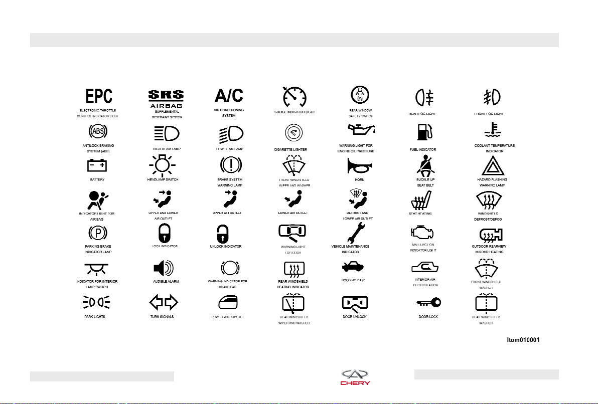
Vehicle Symbols
Consult the symbol table on the following page for a description of the
symbols that may be used on your vehicle and throughout the Owner’s
Manual.
Index
The detailed index at the back of this
Owner’s Manual contains a complete
listing for all vehicle subject matter.
Chery Automobile Co., Ltd.
Page 6
INTRODUCTION – 5
Chery Automobile Co., Ltd.
Page 7

6 – INTRODUCTION
Vehicle Features
This manual includes the current features and information regarding the
Chery Tiggo. All material (including all
standard and available features) contained in this publication is based on
the latest information at the time it
was printed. Therefore, please note
that some of the equipment and ac-
cessories in this publication may not
appear on your vehicle.
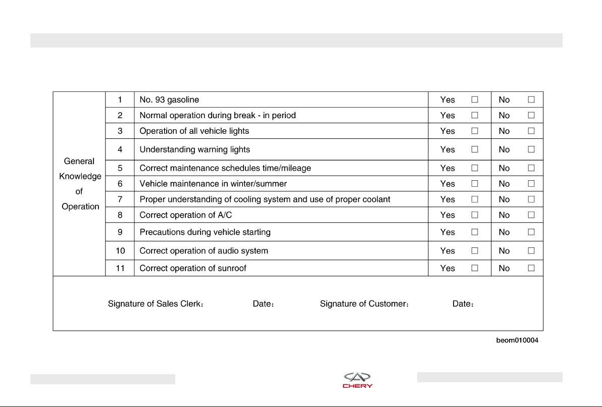
New Vehicle Inspection
Prior to your purchase, your authorized Chery dealer inspected your vehicle based upon the guidelines of the
Chery Automobile Co., Ltd. The dealer
will record the delivery date and affix
its common seal to the inspection certificate.
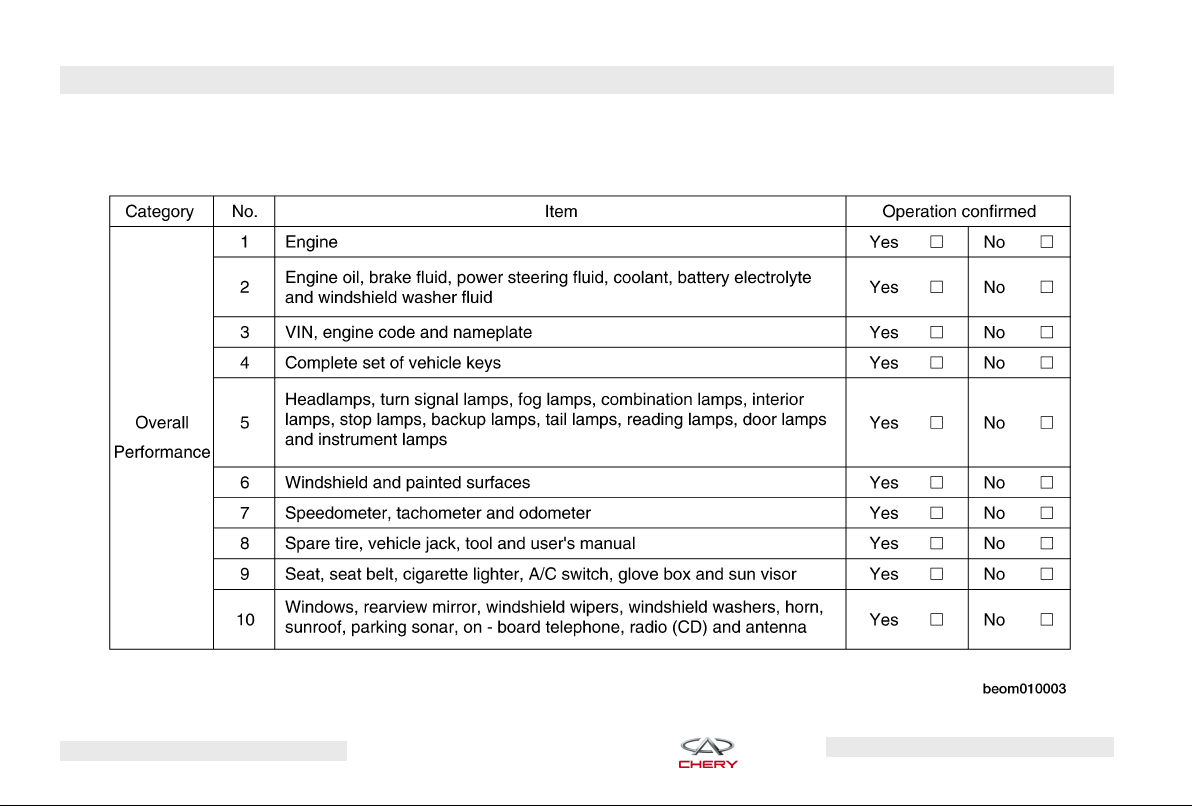
Before you sign the inspection certification, your authorized dealer will instruct you regarding your vehicle’s
performance capabilities according to
its Vehicle Delivery Card, as well as
provide you with general knowledge
of its features and regular operation.
Chery Automobile Co., Ltd.
Page 8
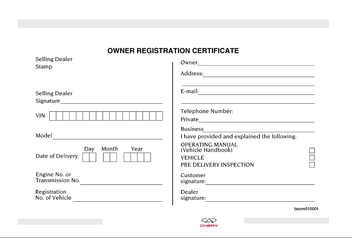
Inspection Certification for Vehicle Delivery
INTRODUCTION – 7
Chery Automobile Co., Ltd.
Page 9
8 – INTRODUCTION
Vehicle Delivery Card
Chery Automobile Co., Ltd.
Page 10
INTRODUCTION – 9
Chery Automobile Co., Ltd.
Page 11

10 – INTRODUCTION
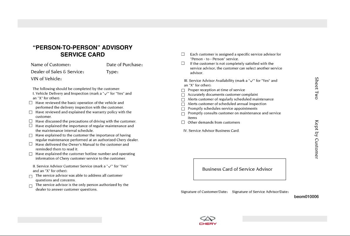
Personal Service
To provide you the best service, your
authorized Chery dealer will provide a
personal service advisor for you during your purchase. If you have any
questions regarding your vehicle,
please ask your service advisor.
Chery Automobile Co., Ltd.
Page 12
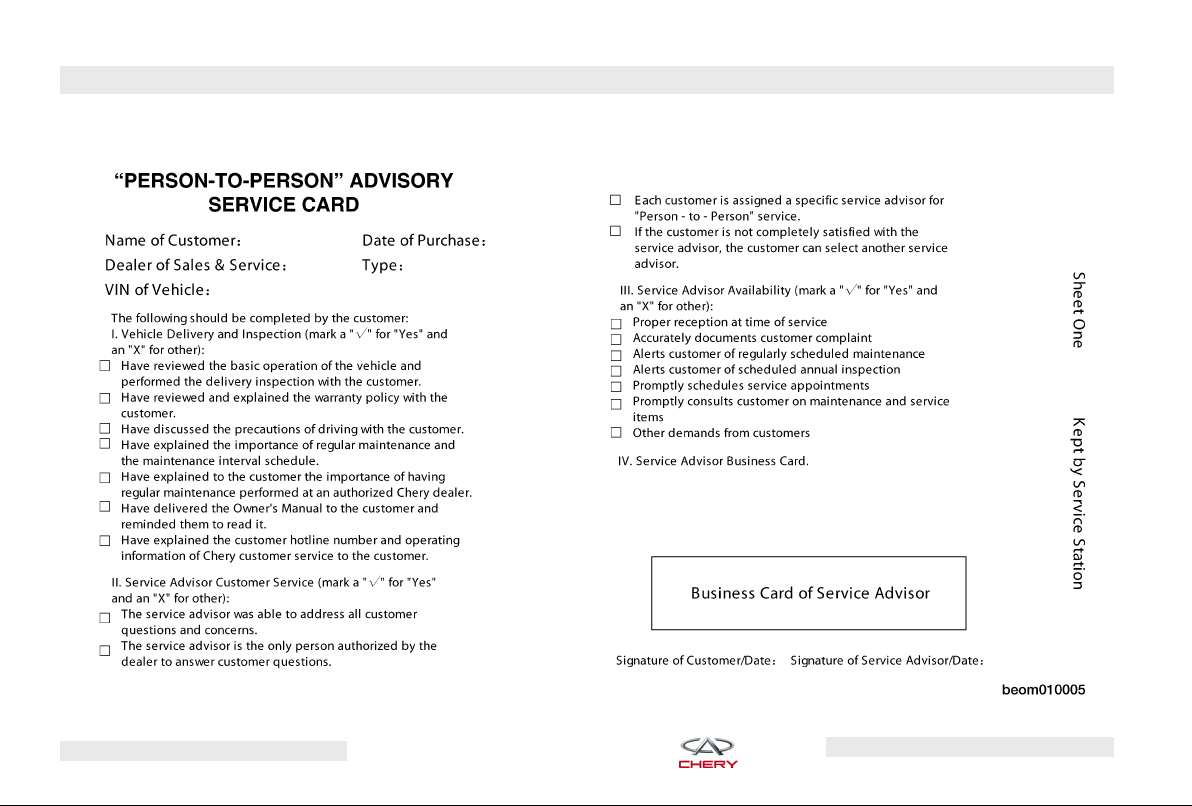
ⴖPERSON-TO-PERSONⴖ Service Advisor Card
INTRODUCTION – 11
Chery Automobile Co., Ltd.
Page 13
12 – INTRODUCTION
Chery Automobile Co., Ltd.
Page 14

INTRODUCTION – 13
Warnings and Cautions
The Owner’s Manual contains Warnings and Cautions regarding operating
procedures that could result in an accident or damage to your vehicle.
Please observe all Warnings and Cautions before operating your vehicle.
Vehicle Identification Number
Vehicle Identification Number (VIN)
Location:
The VIN is on the front corner of the
instrument panel on the passenger
side. It is visible from outside of the
vehicle through the windshield.
WARNING!
Any modifications or alterations to this
vehicle could affect its safety and may
lead to an accident resulting in serious injury or death.
VIN Location
Vehicle Modifications
Modifications to this vehicle could affect its performance and totally void
the manufacturer’s warranty.
Chery Automobile Co., Ltd.
Page 15

14
Chery Automobile Co., Ltd.
Page 16
CONTENTS
15
BEFORE OPERATING YOUR VEHICLE
䉴 Ignition Key 17
컄 Ignition Key Removal
컄 Key-In-Ignition Reminder
컄 Locking Doors With The
Key
컄 Replacement Keys
컄 Remote Keyless Entry
컄 Transmitter Battery
Replacement
17
17
17
17
18
18
䉴 Anti-Theft Security
Protection 19
컄 Vehicle Alarm
컄 Electronic Key Identification
19
19
䉴 Steering Wheel 20
컄 Adjusting Steering Wheel
컄 Horn
20
20
䉴 Door Locks 20
컄 Manual Door Locks
컄 Power Door Locks
컄 “Child-Protection” Door Lock
System (Rear Doors)
20
21
21
䉴 Power Windows 22
컄 Power Window Switches
컄 Auto - Down Feature
컄 Rear Window Safety Switch
Chery Automobile Co., Ltd.
22
22
23
䉴 Occupant Restraints 23
컄 Lap/Shoulder Belts
컄 Lap/Shoulder Belt Warning
Light
컄 Lap/Shoulder Belt Operating
Instructions
컄 Central Two-Point Seat Belt
for Rear Seat
컄 Adjustable Upper Shoulder
Belt Anchorage
컄 Maintenance for Seat Belt
컄 Airbag
컄 Airbag Warning Light
컄 Child Restraint
23
23
23
24
24
24
25
26
26
Page 17

16 – BEFORE OPERATING YOUR VEHICLE
䉴 Operating Safety Tips 28
컄 Transporting Passengers
컄 Locking Your Vehicle
28
28
컄 Exhaust Gas
컄 Interior Vehicle Safety
Inspection
컄 Exterior Vehicle Safety
Inspection
䉴 New Vehicle Break-In
28
Recommendations 30
29
29
컄 Engine Break-In
Recommendations
컄 Braking System Break-In
Recommendations
컄 Tire and Wheel Break-In
Recommendations
30
31
31
Chery Automobile Co., Ltd.
Page 18
BEFORE OPERATING YOUR VEHICLE – 17
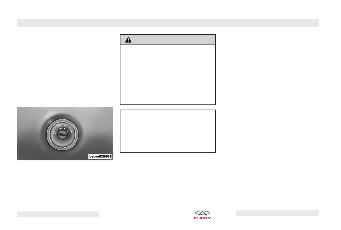
Ignition Key
Ignition Key Removal
Automatic Transaxle
To remove the ignition key from the
ignition switch, place the shift lever in
PARK, turn the ignition switch to the
ACC position, push the key inward, rotate the key to the LOCK position and
remove the key.
Ignition Key Positions
WARNING!
NEVER leave children unattended in
a vehicle. Leaving children unattended
in a vehicle is dangerous. A child or
others could be seriously or fatally injured. Children could operate the
power windows, other controls, or set
the vehicle in motion. NEVER leave the
keys in a vehicle.
CAUTION!
An unlocked car is an invitation to
thieves. Always remove the key from
the ignition and lock all doors when
leaving the vehicle unattended.
Key-In-Ignition Reminder
Opening the driver’s door when the
key is in the ignition will sound a signal to remind you to remove the key.
NOTE:
driver’s door, front passenger’s door,
rear passenger doors and back cargo
If any of the five doors (front
door) is open or the key is in the ignition,
this will prevent the operation of the
power door locks and Remote Keyless
Entry.
Locking Doors With The Key
There are three external door locks
which are located on the driver’s door,
front passenger’s door and back cargo
door. You can insert the key with either side up. To lock the door, turn the
key counter-clockwise; to unlock the
door, turn the key clockwise.
Replacement Keys
Duplication of keys consists of programming a blank key to the vehicle
electronics. A blank key is one which
has never been programmed. See
your authorized Chery dealer if you require replacement or additional keys
for your vehicle.
Chery Automobile Co., Ltd.
Page 19
18 – BEFORE OPERATING YOUR VEHICLE
CAUTION!
Always remove the key from the vehicle
and lock all doors when leaving the vehicle unattended.
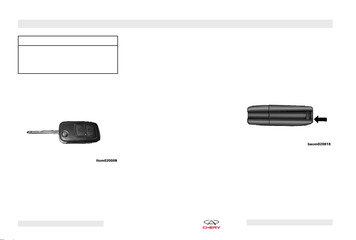
Remote Keyless Entry
This system allows you to lock or unlock the doors remotely using the key
transmitter.
Vehicle Key
To Lock the Doors
Press and release the LOCK button on
the transmitter to lock all doors.
NOTE:
Transmitter and receivers must
be certified to conform to specific regulations in each individual country. Operation is subject to the following two conditions:
•
The device cannot cause harmful interference.
•
The device must accept any interference received, including interference
that may cause undesired operation.
If your key transmitter fails to operate
from a normal distance, check for these
two conditions:
•
Weak batteries in the transmitter (the
expected life of the transmitter battery
is a minimum of three years).
•
Radio transmitter interference, such
as a radio station tower, airport transmitter, and some mobile or CB radios.
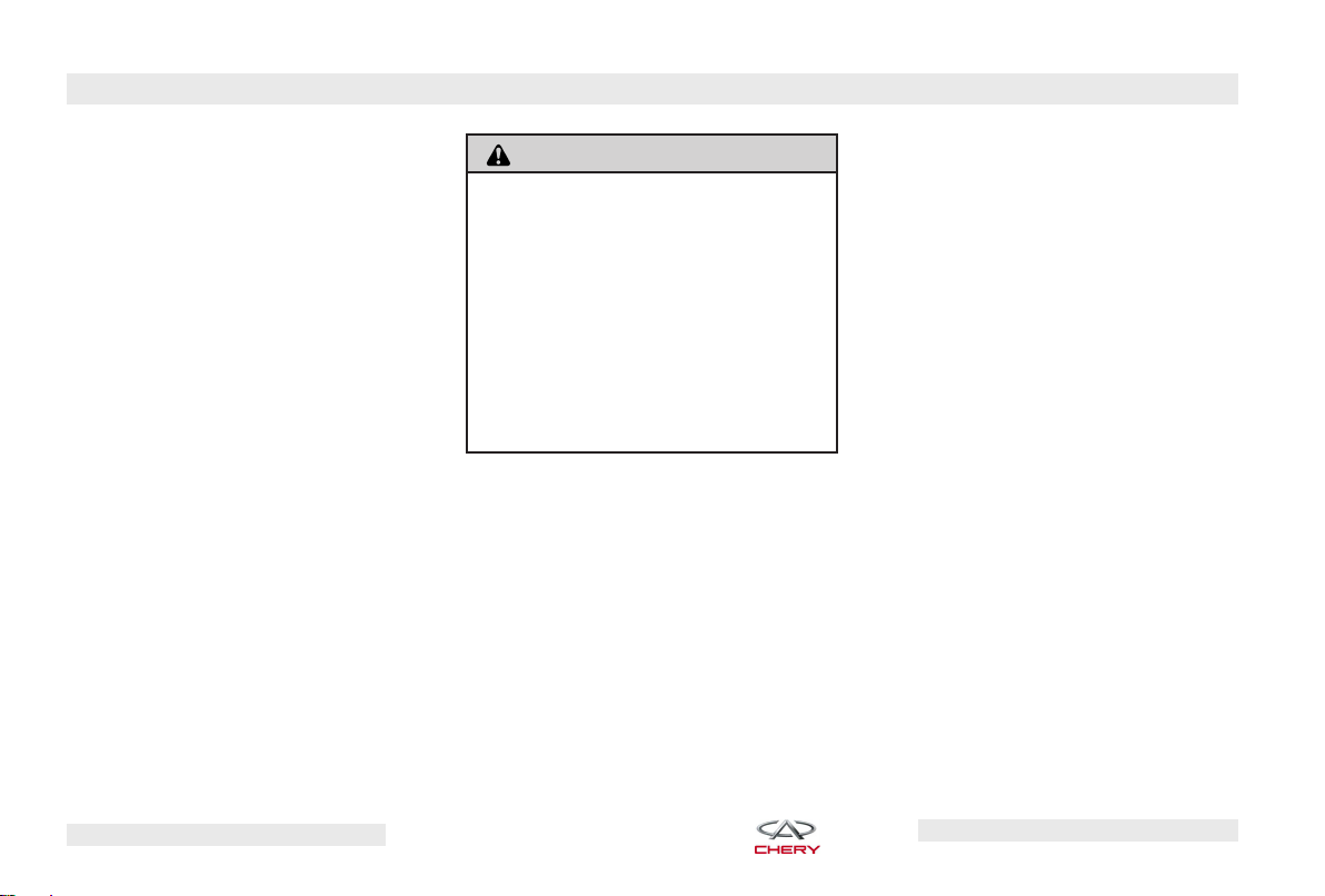
Transmitter Battery Replacement
The recommended replacement battery is CR2032.
• With the transmitter buttons facing
down, use a flat object to pry the two
halves of the transmitter apart. Make
sure not to damage the seal.
Separating Transmitter Halves
• Remove and replace the batteries.
Avoid touching the new batteries with
your fingers. Skin oils may cause battery deterioration. If you touch a battery, clean it with rubbing alcohol.
• To reassemble the transmitter case,
snap the two halves together.
Chery Automobile Co., Ltd.
Page 20
BEFORE OPERATING YOUR VEHICLE – 19
Anti-Theft Security Protection
Vehicle Alarm
With the vehicle armed, if an unauthorized person attempts to unlock any
door, this will cause the vehicle alarm
to trigger. When triggered, the vehicle
alarm will cause all directional signals
to flash continuously and will sound
the horn for a few seconds.
Security Lamp
The security lamp is located in the
front of the instrument panel. The security lamp will flash continuously
when the vehicle is armed.
WARNING!
Only when driver door, passenger
doors and back door are fully closed,
can the vehicle be armed. When the
vehicle is in the anti-theft mode, the
following will occur:
•
Driver door, passenger doors and
back door are locked
•
The security lamp will continuously
flash
Electronic Key Identification
Electronic Key Identification utilizes
engine ⬙no-start⬙ technology to greatly
enhance the vehicle safety and vehicle theft prevention system.
The chip, built into each key, integrates the key, electronic anti-theft
equipment and engine control module into an active theft prevention system. If a key is duplicated without the
authorization of the owner, and the
key has no chip containing the electronic information required for the
anti-theft equipment and engine computer, the engine will not start using
the duplicated key, thus decreasing
the probability of vehicle theft.
In the event that you have lost your
vehicle key, you should go to an authorized Chery dealer to obtain a replacement key. The dealer can make a
new key for your vehicle and deactivate your lost key.
Chery Automobile Co., Ltd.
Page 21

20 – BEFORE OPERATING YOUR VEHICLE
Steering Wheel
Adjusting Steering Wheel
The steering wheel can be adjusted to
make the driver more comfortable.
Pull down the locking lever to move
the steering wheel upward and downward. After the proper adjustment,
pull the locking lever back to its original position to secure the steering
wheel in place.
Adjustable Steering Wheel
WARNING!
Do not adjust the steering wheel while
driving. Adjusting the steering wheel
while driving could cause the driver to
lose control of the vehicle.
Horn
Horn Position
Press the center push pad on the
steering wheel to operate the horn.
The horn will still work with the ignition switch in the OFF position.
Door Locks
Manual Door Locks
The front doors can be locked/
unlocked by turning the key in the
door lock cylinder. Use the manual
door lock switch on the door panel to
unlock the doors from inside of the vehicle. If the rear door switch is in the
locked position when the door is
closed, the door will lock. It is recommended to use the Remote Keyless
Entry to lock the doors.
Manual Lock Switch
Chery Automobile Co., Ltd.
Page 22
BEFORE OPERATING YOUR VEHICLE – 21
WARNING!
For personal security and safety lock
the vehicle doors when you drive, as
well as when you park and leave the
vehicle. When leaving the vehicle, always remove the key from the ignition
switch, and lock your vehicle. Do not
leave children unattended in the vehicle, or with access to an unlocked vehicle. Unsupervised use of vehicle
equipment may cause severe personal
injuries or death.
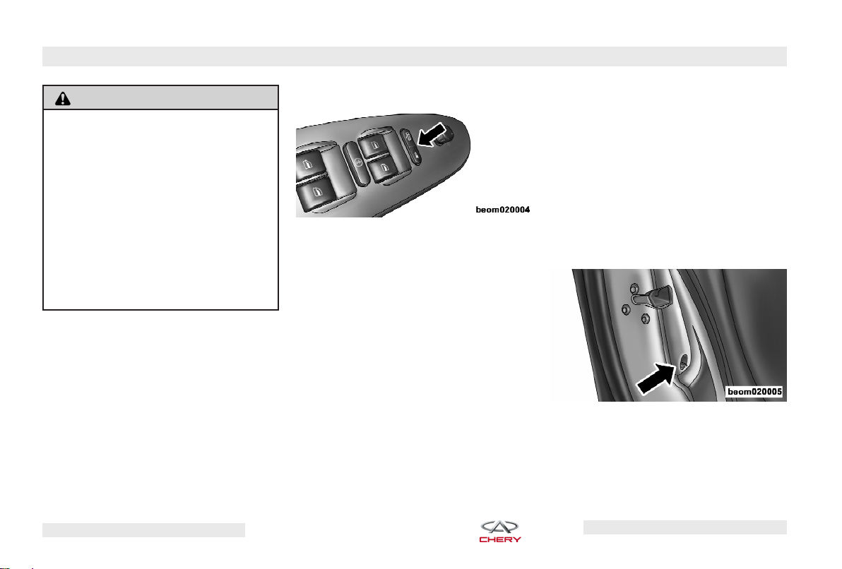
Power Door Locks
A door lock switch is located on the
driver’s door panel. Press this switch
to lock or unlock the doors.
Power Door Lock Switch
To prevent you from locking your key
in the vehicle, the power door LOCK
switch will not operate while the key is
in the ignition and either front door is
open. An audible chime will sound as
a reminder to remove the key from the
ignition switch.
NOTE:
The doors will lock automatically on vehicles with power door locks
when the vehicle speed is above 45
km/h. The auto lock feature is activated
once the engine starts. The doors will
unlock automatically on vehicles with
power door locks when the engine is
turned off and the transaxle is in NEUTRAL or PARK.
“Child-Protection” Door Lock
System (Rear Doors)
The Rear Door Child-Protection Locks
are located inside the rear door. Turn
the child lock control upward or downward to the lock or unlock position (as
shown by the icons).
Child Lock Control
Chery Automobile Co., Ltd.
Page 23
22 – BEFORE OPERATING YOUR VEHICLE
WARNING!
•
To avoid trapping passengers in the
vehicle during a collision, remember that the rear doors can only be
opened from the outside when the
child protection locks are engaged.
•
In hot weather, the temperature inside the vehicle can rise very quickly
after the engine is turned off. Do not
leave animals or children inside
parked vehicles in hot weather; interior heat buildup may cause serious injury or death. If even left
there for a short time, it is likely that
serious injury or death could occur.
NOTE:
system engaged, move the lock switch
up to the unlocked position, roll down
the window, and open the door with the
outside door handle.
For emergency exit with the
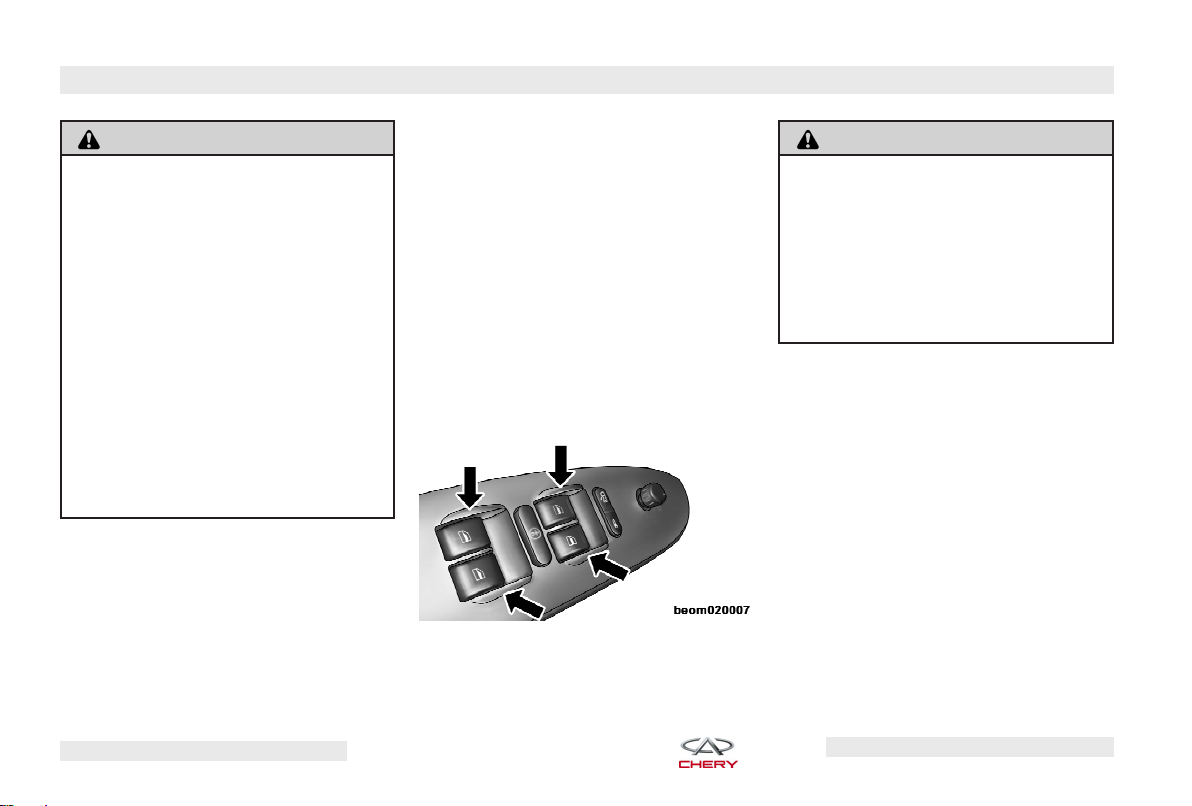
Power Windows
Power Window Switches
The driver’s door trim panel has
switches that operate all four power
windows. There are single window
controls on each passenger door trim
panel that operate each respective
passenger door window. The windows
will operate only when the ignition
switch is turned to the ON position
and will remain active for 60 seconds
after the ignition key is removed.
Power Window Switches
WARNING!
Never leave children in a vehicle with
the key in the ignition switch. Occupants, particularly unattended children
can become trapped by the windows
while operating the power window
switches which may result in serious
injury or death.
Auto - Down Feature
All four power window switches have
the Auto-Down feature. Press and hold
the window switch for one second, release, and the window will go down
automatically.
NOTE:
while pressing the LOCK button on the
key transmitter, the windows will automatically be closed. If the vehicle is
equipped with a 2.4L engine, the power
windows can be closed using the key
transmitter, but you must press and hold
the LOCK button until all windows are
closed completely.
If any power windows are open
Chery Automobile Co., Ltd.
Page 24
BEFORE OPERATING YOUR VEHICLE – 23
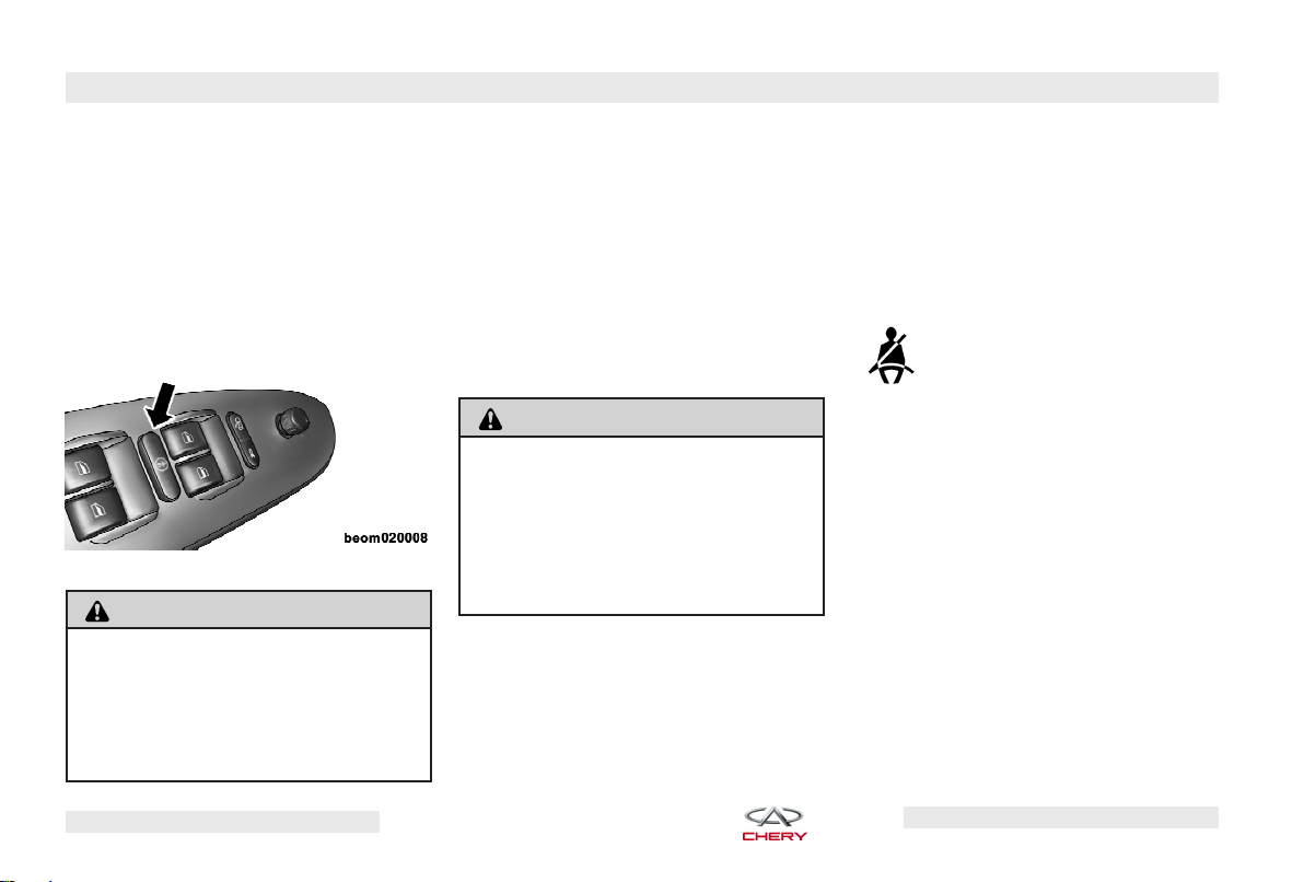
Rear Window Safety Switch
There is a safety switch on the driver
door trim panel. Press the switch to
lock all passenger side power windows. Cancel this feature by pressing
the switch again. This feature is recommended if there are children in your
vehicle.
Rear Window Safety Switch
WARNING!
There is no anti-pinch protection when
the window is closing. To avoid personal injury, be sure to clear all arms,
hands, fingers and all objects away
from the window path before closing.
Occupant Restraints
Lap/Shoulder Belts
Be sure everyone in your vehicle is in
a seat and properly using a seat belt.
Never use a lap/shoulder belt or lap
belt for more than one person. Make
sure that the seat belt is properly fastened without looseness, twists, or obstruction.
WARNING!
A lap belt worn too high can increase
the risk of internal injury in a collision.
The belt forces won’t be at the strong
hip and pelvic bones, but across your
abdomen. Always wear the lap belt as
low and snug as possible.
In a collision, an unrestrained child,
even a tiny baby, can be propelled inside the vehicle if not properly restrained. The force required to hold
even an infant on your lap could become so great that you could not hold
the child, no matter how strong you
are. The child and others can be badly
injured. Any child riding in the vehicle
should be in an appropriate restraint
for the child’s size.
Lap/Shoulder Belt Warning Light
With the ignition switch ON,
this light is illuminated. It
will not turn off until the
driver properly attaches the
seat belt.
Lap/Shoulder Belt Operating
Instructions
The seat belt latch plate is above the
back of the front seat, next to your
shoulder. Grasp the latch plate and
pull out the belt. While pulling out the
belt, slide the latch plate up the webbing as far as necessary to allow the
belt to go around your lap. When the
belt is long enough to fit, insert the
latch plate into the buckle until you
hear a ⬙click⬙.
Chery Automobile Co., Ltd.
Page 25
24 – BEFORE OPERATING YOUR VEHICLE
WARNING!
A belt that is fastened into the wrong
buckle will not protect you properly.
Always buckle your belt into the nearest buckle.
To release the belt, push the red button on the buckle. The belt will automatically retract to its stowed position. If necessary, slide the latch plate
down the webbing to allow the belt to
retract fully.
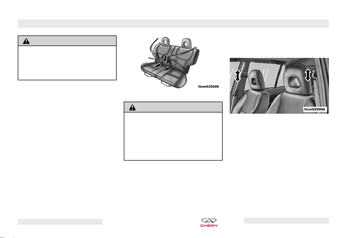
Central Two-Point Seat Belt for
Rear Seat
This seat belt length cannot be adjusted automatically. The seat belt is
adjusted by an adjustable buckle that
slides along its length to provide the
proper fit for the passenger. When the
belt has been adjusted to fit the passenger, insert the latch plate into the
buckle until you hear a ⬙click⬙, and
then adjust the length of seat belt
manually across your abdomen.
Rear Central Two-Point Seat Belt
WARNING!
A twisted belt cannot perform properly.
In a collision, it could even cut into its
passenger . Be sure the belt is straight.
If you can’t straighten a belt in your vehicle, take it to an authorized Chery
dealer and have it repaired.
Adjustable Upper Shoulder Belt
Anchorage
In the driver’s seat and front passenger’s seat, the shoulder belt can be
adjusted upward or downward to position the belt away from the driver’s or
passenger’s neck. Push and fully de-
press the button to release the anchorage, and move it up or down to
the position that fits you best.
Adjustable Upper Shoulder Belt
Anchorage
Maintenance for Seat Belt
Inspection Of Seat Belt
The seat belt should be inspected
regularly for damage or frays. Damaged parts must be replaced immediately. Seat belt assemblies must be
replaced after a collision if they have
been damaged.
Chery Automobile Co., Ltd.
Page 26
BEFORE OPERATING YOUR VEHICLE – 25
WARNING!
Do not disassemble or modify the seat
belt.
Washing Seat Belt
The seat belt should be washed with
vehicle detergent or warm water and
allowed to dry naturally.
WARNING!
Never use chemical detergents, boiled
water, bleach or dye to wash the seat
belt.
Never allow water to enter the belt retractor.
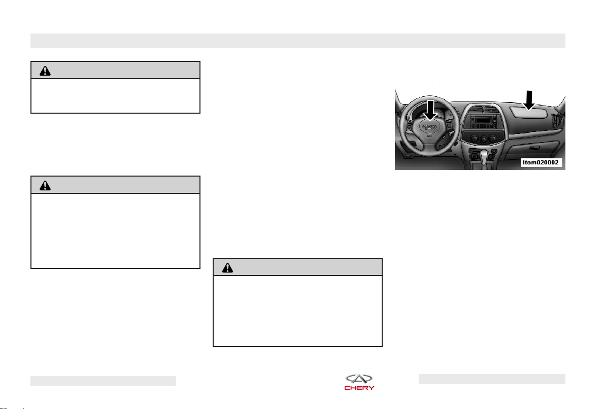
Airbag
The airbags work with the seat belts to
properly restrain the driver and frontseat passenger in the event of a collision.
NOTE:
As the triggered airbags deflate you may see some smoke-like particles. The particles are a normal byproduct of the process that generates
the nontoxic gas used for airbag inflation.
The front occupants must be sitting as
upright as possible in order to be effectively protected.
WARNING!
Always properly position your seat belt
to maintain the proper distance from
the steering wheel. Only then can the
airbag provide optimal protection during a collision.
Front Airbags
Front Airbags
The seat and backrest must be positioned correctly for the airbag to provide optimal protection during a collision. The vertical sitting posture is
best when the lower back is in contact
with the seat backrest as much as possible and the inclination of seat backrest is not over 30 degrees. Never position the front seat too close to the
instrument panel. While driving, the
steering wheel should be held with
the arms slightly flexed. This is an
ideal driving posture, which helps to
decrease the risk of the driver being
Chery Automobile Co., Ltd.
Page 27
26 – BEFORE OPERATING YOUR VEHICLE
injured in a collision in which the airbag does not deploy.
The front airbag will deploy in a moderate to severe frontal collision or
within the scope of left/right 30 degrees collisions. When it touches the
occupant, it instantly deflates to cushion the forward movement of the occupant. An airbag is designed to deploy
in moderate to severe frontal or nearfrontal crash. The airbag will deploy
only if the impact speed is above the
system’s designated threshold level.
WARNING!
Do not put anything on or around the
front airbag covers or attempt to
manually open them. Take your vehicle
to an authorized Chery dealer for steering wheel, steering column and airbag
system service or you could be injured
because of accidental airbag deployment.
Airbag Warning Light
When the ignition switch is in ON, the
warning light in the instrument panel
will be turned on and remain on for
3-4 seconds. If the light does not come
on, remains illuminated after you start
the vehicle, or if it comes on as you
drive, take your vehicle to an authorized Chery dealer for inspection. It is
suggested by the airbag manufacturer
that the airbag should be replaced after 10 years of service because the efficiencies of the inflating agent and airbag deteriorate. If you are not clear
about the service life of your vehicle’s
airbag, your authorized Chery dealer
can answer any questions or address
any concerns you may have. Take your
vehicle only to an authorized Chery
dealer for service.
Child Restraint
Please follow the manufacturer’s directions exactly when installing an infant
or child restraint.
WARNING!
In a collision, an unrestrained child,
even a tiny baby, can become a missile inside the vehicle. The force required to hold even an infant on your
lap could become so great that you
could not hold the child, no matter how
strong you are. The child and others
could be badly injured. Any child riding
in your vehicle should be in a proper
restraint for the child’s size.
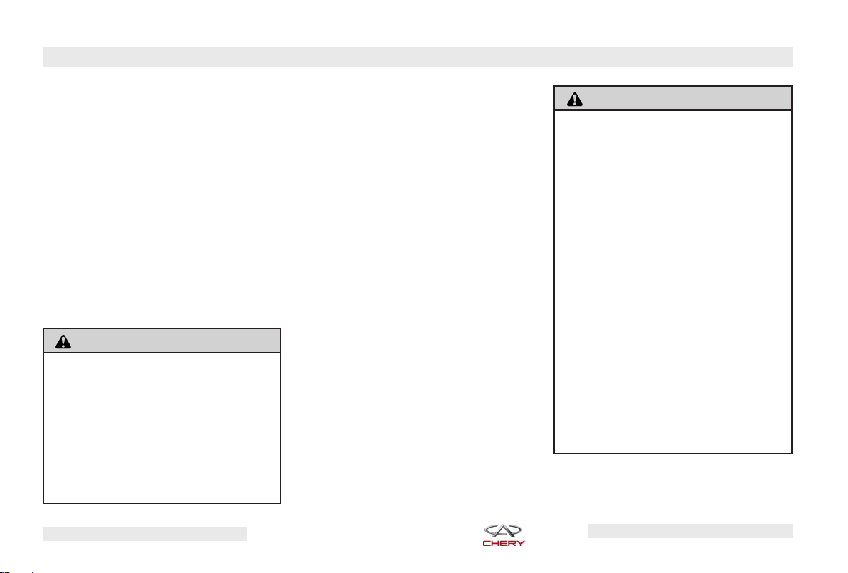
NEVER use a backward-facing child
restraint seat on a passenger seat protected by an airbag. A backwardfacing child restraint should only be
used in a rear seat. A backward-facing
child restraint in the front seat may be
struck by a deploying passenger airbag which may cause severe or fatal
injury to the infant.
Chery Automobile Co., Ltd.
Page 28
BEFORE OPERATING YOUR VEHICLE – 27
For children under 12 years old or
shorter than 150 cm, the special child
restraint must be used properly with
an infant restraint, child restraint, or
with the heightened seat cushion. The
child restraint must be applicable and
government-authorized. Maximum
child safety can be obtained when the
safety seat works together with the
seat belt.
Children who weigh less than 10 kg or
are less than 1 year old should be
placed in the baby bed on the rear
seat with the baby lying flat and on
the bed and restrained. For infants,
use the backward-facing child restraint.
Rearward Facing Child Seat
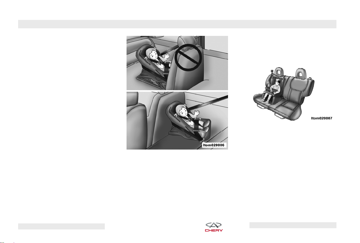
Children who weigh between 10 kg to
18 kg or are less than 4 years old
should use child restraints on the rear
seat.
Child Restraint Seat
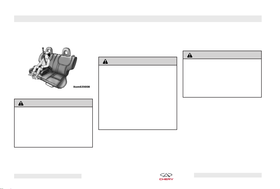
Children who weigh between 18 kg to
36 kg or are between 4 and 12 years
old should sit on the heightened seat
cushion on the rear seat. The adjustable auxiliary seat belt fixed on the
heightened seat cushion can ensure a
child uses the seat belt properly. The
heightened seat cushion positions the
Chery Automobile Co., Ltd.
Page 29
28 – BEFORE OPERATING YOUR VEHICLE
belt away from the child’s neck and
the lap belt should fit across the
child’s abdomen.
Heightened Seat Cushion
WARNING!
Each child restraint is intended for one
child only.
According to local traffic laws, children
are forbidden to sit in the front seat
and should use the applicable child restraints.
Operating Safety Tips
Transporting Passengers
NEVER TRANSPORT PASSENGERS IN
THE CARGO AREA.
WARNING!
It is extremely dangerous to ride in a
cargo area, inside or outside of a vehicle. In a collision, people riding in
these areas are more likely to be seriously injured or killed.
Do not allow people to ride in any area
of your vehicle that is not equipped
with seats and seat belts.
Be sure everyone in your vehicle is in
a seat and using a seat belt properly.
Locking Your Vehicle
Always remove the key from the ignition switch and lock all doors when
leaving the vehicle unattended, even
in your own driveway or garage. Try to
park your vehicle in a well-lit area and
avoid leaving articles of value exposed.
Exhaust Gas
WARNING!
Exhaust gases can injure or kill. They
contain carbon monoxide (CO), which
is colorless and odorless. Breathing it
can make you unconscious and can
eventually poison you and lead to
death.
Do not run the engine in a closed garage or in confined areas any longer
than needed to move your vehicle in
or out of the area.
If it is necessary to sit in a parked vehicle with the engine running, adjust
your heating or cooling controls to
force outside air into the vehicle. Set
the blower at high speed.
Chery Automobile Co., Ltd.
Page 30

BEFORE OPERATING YOUR VEHICLE – 29
If you are required to drive with the
back door open, make sure that all
windows are closed and the climate
control BLOWER switch is set at high
speed. DO NOT use the recirculation
mode.
The best protection against carbon
monoxide entry into the vehicle passenger compartment is a properly
maintained engine exhaust system.
Interior Vehicle Safety Inspection
Seat Belts
Inspect the belt system periodically,
checking for cuts, frays, and loose
parts. Damaged parts must be replaced immediately. Do not disassemble or modify the system.
Front seat belt assemblies must be replaced after a collision. Rear seat belt
assemblies must be replaced after a
collision if they have been damaged
(i.e., bent retractor, torn webbing,
etc.). If there is any question regarding
belt or retractor condition, replace the
belt.
Airbag Warning Light
The light should come on and remain
on for 3-4 seconds as a bulb check
when the ignition switch is first turned
ON. If the light is not lit during starting, see your authorized Chery dealer.
If the light stays on, flickers, or comes
on while driving, have the system
checked by an authorized Chery
dealer.
Defroster
Check the operation by selecting the
defrost mode and place the blower
control on high speed. You should be
able to feel the air directed against
the windshield. See your authorized
Chery dealer for service if your defroster is inoperable.
Exterior Vehicle Safety Inspection
Tires
Examine tires for excessive tread wear
and uneven wear patterns. Check the
tires for the following:
• Stones, nails, glass, or other objects
lodged in the tread
• Tread and sidewall for cuts and cracks
• Proper pressure (including spare)
• Wheel nuts for proper torque
Lights
Have an assistant observe the operation of exterior lights while you work
the controls. Check turn signal and
high beam indicator lights on the instrument panel. Check the following
lights for proper operation:
• Low beam headlights
• High beam headlights
• Turn signals
Chery Automobile Co., Ltd.
Page 31

30 – BEFORE OPERATING YOUR VEHICLE
• Tail Lamps
• Stop Lights
Fluid Leaks
Check the area under the vehicle after
overnight parking. If a leak is suspected, the cause should be located
and corrected immediately. Check the
following for possible leaks:
• Fuel
• Engine coolant
• Engine oil
• Power steering fluid
• Brake fluid
New Vehicle Break-In
Recommendations
Engine Break-In
Recommendations
Vehicle frictional resistance is much
greater when the vehicle is new. The
result of proper engine break-in will
impact the service life, operating reliability and vehicle economical efficiency. The following is the proper engine break-in procedure:
During first 1,000 km of operation:
• Do not allow the engine speed to exceed 3,000 rpm
• Do not exceed 100 km/h
• Do not operate the engine at maxi-
mum speed when upshifting
During 1,000-1,500 km of operation:
• Driving speed can be gradually increased to greater than 100 km/h
• Engine speed can be gradually increased to its maximum
Safety Tips During Engine Break-In
The maximum engine speed is 6,000
rpm. If the vehicle is equipped with a
manual transmission, the vehicle must
be shifted into the next highest gear
before the needle of tachometer is in
the red range.
Chery Automobile Co., Ltd.
Page 32

BEFORE OPERATING YOUR VEHICLE – 31
NOTE:
To utilize your vehicle efficiently, avoid operating the engine at unnecessary high speeds. To optimize fuel
efficiency, the vehicle should be shifted
to the next highest gear position at the
proper engine/road speed. This will decrease operational noise and help reduce environmental pollution.
NOTE:
The engine is also at risk if it is
operated at too low an engine speed. It
should be shifted to a lower gear position in order to maintain the proper engine speed.
NOTE:
The engine must be at normal
operating temperature before operating
the engine at high speed.
Braking System Break-In
Recommendations
The brakes cannot provide the ideal
friction to stop during the vehicle’s
first 200 km of operation. You should
depress the brake pedal firmly to increase friction and improve stopping
capability.
Tire and Wheel Break-In
Recommendations
New tires require a brief break-in period. Your vehicle should be driven
slowly and especially carefully within
the first 100 km of driving.
Vehicle wheel nuts must be retightened to the specified torque after
the first 800 km of driving. Also, when
a wheel has been replaced or after
wheel nuts have been loosened, they
must be re-tightened to the specified
torque after driving 800 km.
Chery Automobile Co., Ltd.
Page 33

32
Chery Automobile Co., Ltd.
Page 34

CONTENTS
33
FEATURES OF YOUR VEHICLE
䉴 Mirrors 35
컄 Inside Rearview Mirror
컄 Outside Mirror
컄 Outside Mirrors Folding
Feature
컄 Power Remote Control
Mirrors
컄 Heated Remote Control
Mirrors
컄 Vanity Mirrors
35
35
35
35
36
36
䉴 Windshield Wipers and
Washers 36
컄 Front Windshield Wipers
and Washers
컄 Rear Window Wiper and
Washer
37
38
䉴 Seats 39
컄 Manual Front Seat
Adjustments
컄 Manual Rear Seat
Adjustments
컄 Head Restraints
컄 Heated Seats (If Equipped)
39
40
42
42
䉴 Lights 43
컄 Headlights, Parking Lights
(Front Position Lights,
Instrument Panel Lights and
License Light)
컄 High Beam/Low Beam
Select Switch
컄 Flash to Pass
컄 Front Fog Lights
(If Equipped)
Chery Automobile Co., Ltd.
43
43
44
44
컄 Rear Fog Lights
컄 Turn Signals
컄 Dimmer Control
컄 Headlight Leveling System
컄 Front Interior Lighting
컄 Rear Interior Lighting
컄 Keyhole Light
컄 Brake Lights
컄 Reverse Lights
44
44
45
45
45
45
46
46
46
䉴 Electrical Power Outlet 46
䉴 Cruise Control 47
컄 Cruise Control (If Equipped)
컄 To Activate
컄 To Set A Desired Speed
컄 To Deactivate
47
47
47
48
Page 35

34 – FEATURES OF YOUR VEHICLE
컄 To Vary The Set Speed
컄 To Accelerate for Passing
컄 To Resume Set Speed
48
48
48
䉴 Sunroof (If Equipped) 49
컄 Opening Sunroof
컄 Closing Sunroof
컄 Anti-Pinch Feature
컄 Anti-Pinch Override
컄 Tilt UP Feature
49
49
49
49
49
컄 Tilt Down Feature
컄 Sunshade Operation
49
50
䉴 Cigarette Lighter and
Ashtray 50
컄 Cigarette Lighter
컄 Front Ashtray
컄 Rear Ashtray
50
50
51
䉴 Cup and Bottle Holders 51
컄 Front Cupholder
51
컄 Rear Cupholder
51
䉴 Storage Areas 52
컄 Center Console
컄 Overhead Console
컄 Glove Box
컄 Auxiliary Storage
Compartments
컄 Cargo Area
컄 Roof Luggage Rack
52
52
52
53
53
55
Chery Automobile Co., Ltd.
Page 36

FEATURES OF YOUR VEHICLE – 35
Mirrors
Inside Rearview Mirror
Adjust the mirror to a center view position through the rear window. Night
time headlight glare can be reduced
by moving the control lever under the
mirror to the night position.
NOTE:
should be adjusted in the day position
before using the night position.
1 - Day 2 - Night
The mirror viewing range
Inside Rearview Mirror
Outside Mirror
For the driver’s maximum benefit, adjust the outside mirrors to center on
the adjacent lane of traffic, slightly
overlapping the view obtained from
the inside mirror.
WARNING!
Vehicles and other objects seen in the
outside mirrors will appear smaller and
farther away than they really are. Relying solely on your door mirrors could
cause you to collide with another vehicle or object.
Outside Mirrors Folding Feature
Outside mirrors can be folded manually. The outside mirror can be restored to its normal position by unfolding it outward to the proper
position.
Power Remote Control Mirrors
The power mirror switch is located on
the driver’s door trim. A rotary knob
selects the left mirror, right mirror, or
off position.
Power Mirror Adjust Switch
Outside mirrors can be adjusted remotely on the driver’s door trim panel
only when the ignition switch is in the
ON position. After selecting a mirror,
Chery Automobile Co., Ltd.
Page 37

36 – FEATURES OF YOUR VEHICLE
toggle the knob in the same direction
you want the mirror to move. When
finished, return the knob to the center
middle position to guard against accidental mirror movement.
Mirror Directions
Heated Remote Control Mirrors
The outside mirrors are heated to
melt frost or ice. This feature is activated whenever the rear window defogger is activated. Refer to ⬙Rear Window Defroster⬙ in Chapter 5 of this
manual for more information.
Vanity Mirrors
Vanity Mirror
Vanity mirrors are equipped on both
driver side and passenger side sun visors. To use the vanity mirrors, rotate
the sun visor down and swing the mirror cover downward.
Windshield Wipers and
Washers
The wiper and washer control lever is
located on the right side of the steering column. The wiper/washer operates only when the ignition switch is in
the ON position.
CAUTION!
In cold weather, always turn the wiper
switch OFF and allow the wipers to return to the park position before shutting off the engine. If the wiper switch
is left ON and the wipers freeze to the
windshield, damage to the wiper motor may occur when the vehicle is restarted.
Always remove any buildup of snow
that prevents the windshield wiper
blades from returning to the park position. If the windshield wipers are operated before the snow is removed,
damage to the wiper motor may occur.
Never operate the windshield wipers
when the windshield is dry . Operating
the windshield wipers on a dry windshield will scuff the windshield and
permanently damage the wiper blades.
Chery Automobile Co., Ltd.
Page 38

FEATURES OF YOUR VEHICLE – 37
Front Windshield Wipers and
Washers
High and Low Speed Feature
High and Low Speed Control
Move the lever down to the first setting past the intermittent settings for
low speed wiper operation, or to the
second setting past the intermittent
settings for high speed wiper
operation.
Mist Feature
Mist Control Front Wiper Intermittent Control
Move the lever to the MIST position to
activate a single wipe cycle to clear
the windshield. The wiper will continue to operate until you release the
lever.
Intermittent Wiper Feature
Move the lever down to the INT position to make a single wiping cycle with
a pause between cycles.
Chery Automobile Co., Ltd.
Page 39

38 – FEATURES OF YOUR VEHICLE
Windshield Washer Feature
Windshield Washer Control
To activate the washer, pull the Windshield Wiper/Washer Control lever toward you and hold it for as long as
washer spray is desired. If you activate
the washer while the wiper control is
in the OFF position, the wipers will
operate for three wipe cycles then
turn OFF.
CAUTION!
The windshield washer operating time
should be no longer than 10 seconds.
(Continued)
CAUTION! (Continued)
Operating the windshield washer when
the fluid tank is empty may damage
the washer motor.
Rear Window Wiper and Washer
Normal Speed Feature
Rear Wiper Normal Speed Control
Rotate the end of the wiper switch lever to the ON position for normal rear
wiper speed operation.
Intermittent Wiper Feature
Rear Wiper Intermittent Control
Rotate the end of the wiper switch lever to the INT position to make a
single wiping cycle with a pause between cycles.
Rear Window Washer Feature
Rear Window Washer Control
Chery Automobile Co., Ltd.
Page 40

FEATURES OF YOUR VEHICLE – 39
To activate the rear washer, rotate the
end of the wiper switch lever downward to the last setting past the OFF
position and hold it for as long as
washer spray is desired.
CAUTION!
The rear washer operating time should
be no longer than 10 seconds.
Operating the rear washer when the
fluid tank is empty may damage the
washer motor.
Seats
Manual Front Seat Adjustments
Forward and Rearward Adjustment
The manual seat adjustment bar is at
the front of the seat, near the floor.
Pull the bar upward and slide the seat
forward or backward. Release the bar
once the seat is in the desired position. To confirm the seat is locked into
place, attempt to move the seat forward and backward after adjusting the
seat.
Manual Seat Adjustment
WARNING!
Never adjust the seat while driving.
The sudden movement of the seat
could cause you to lose control. Adjust
the seat only while the vehicle is
parked.
Recliner Adjustment
The recliner control lever is on the
outboard side of the seat. To recline
the seat, lean forward slightly before
lifting the lever, then lean back to the
desired position and release the lever. Lean forward and lift the lever to
return the seat back to its normal
position.
Seat back Recliner Lever
Manual Seat Bottom Cushion
Adjustment
The inclined height of driver’s seat
cushion can be adjusted by using the
knob on the outboard side of the seat.
To confirm the seat cushion is locked
Chery Automobile Co., Ltd.
Page 41

40 – FEATURES OF YOUR VEHICLE
into place, attempt to move the seat
cushion after adjusting.
Seat Bottom Cushion Adjustment Knob
Manual Rear Seat Adjustments
Forward and Rearward Adjustment
The manual seat adjustment bar is at
the front of the rear seats, near the
floor. Pull the bar upward and slide
the seat forward or backward. Release
the bar once the seat is in the desired
position. To confirm the seat is locked
into place, attempt to move the seat
forward and backward after adjusting
the seat.
Manual Rear Seat Adjustment
Folding Rear Seats
To provide additional storage area,
each rear seat back can be folded forward. Pull the strap forward to move
the seat forward and flat.
Folding Rear Seats
Chery Automobile Co., Ltd.
Rear Seats Folded Flat
NOTE:
Prior to folding the rear seats,
be sure that the front seats are fully upright and positioned forward. This will allow the rear seat to fold down easily.
Removing Rear Seats
To provide additional storage area,
the rear seats can be removed. Perform the following procedure to remove the rear seats.
Page 42

FEATURES OF YOUR VEHICLE – 41
• Fold the seat back down, and press
the rear seat release lever.
Rear Seat Release Lever
• Slowly pivot the entire seat forward.
Pivoting Rear Seat
• Release the seat and pull the seat out
and away from the lower bracket.
Releasing Rear Seat
• Remove the seat from the vehicle.
Removing Rear Seat
Installing Rear Seat
Install the seats in the reverse order of
removal.
WARNING!
•
It is extremely dangerous to ride in
a cargo area, inside or outside of a
vehicle. In a collision, people riding
in these areas are more likely to be
seriously injured or killed.
•
Do not allow people to ride in any
area of your vehicle that is not
equipped with seats and seat belts.
•
Be sure everyone in your vehicle is
in a seat and using a seat belt properly.
•
In a collision, you or others in your
vehicle could be injured if seats are
not properly latched to their floor
attachments. Always be sure that
seats are fully latched.
Chery Automobile Co., Ltd.
Page 43

42 – FEATURES OF YOUR VEHICLE
Reclining Rear Seat
For additional comfort, pull the seat
strap forward just enough to release
the seat back latch. Then, push the
seat back to the desired reclined position, and release the strap.
Reclining Rear Seat
Head Restraints
Head restraints can reduce the risk of
whiplash injury in an accident. Head
restraints can only protect the occupant if they are adjusted properly.
Front Head Restraints
Head Restraint Adjustment
Adjusting the Head Restraints
Press the lock release button, then
pull up on the head restraint to raise
and push down to lower.
Removing or Installing the Head
Restraints
To remove the head restraint, you
must simultaneously press the lock release button and pull out the head restraint. To reinstall the head restraint,
insert the posts into the sleeves and
push the head restraint downward until it locks into place.
Rear Head Restraints
The adjustment of rear head restraints
is the same as the front head restraints.
WARNING!
Never sit in a seat or allow a passenger to sit in a seat without having the
head restraint in place and adjusted
properly as it may result in personal
injury to you or your passenger in an
accident.
Heated Seats (If Equipped)
Heated seats provide comfort and
warmth in cold weather. The heaters
provide the same heat level for both
the seat cushion and back. The driver
seat and front passenger seat are
heated.
Chery Automobile Co., Ltd.
Page 44

FEATURES OF YOUR VEHICLE – 43
The controls for each seat heater are
located near the bottom center of the
instrument panel. After turning the ignition ON, you can choose from High
or Low heat settings. When the switch
is in the middle position, the seat
heater is Off. Each switch is equipped
with LED lights to indicate the level of
heat that each seat is set at.
Heated Seat Switches
Lights
Headlights, Parking Lights (Front
Position Lights, Instrument Panel
Lights and License Light)
Headlight Control
Turn the end of the multifunction
switch lever to the first setting for
parking lights (front position lights, instrument panel lights and license
light). Turn the end of the lever to the
second setting for headlight operation.
NOTE:
the ignition switch is ON. The headlights
The headlights only work when
will turn off automatically when the engine is starting or when the engine is
stopped.
High Beam/Low Beam Select
Switch
High Beam Control
When the multifunction lever is in the
headlight position, push the multifunction lever away from you to switch
the headlights to the HIGH beam position. When the high beam position is
selected, the high beam indicator on
the instrument cluster will illuminate
immediately. Pull the lever toward you
to switch the headlights back to LOW
beam.
Chery Automobile Co., Ltd.
Page 45

44 – FEATURES OF YOUR VEHICLE
Flash to Pass
While driving, you can signal another
vehicle with your headlights by lightly
pulling the multifunction lever toward
you. This will cause the headlights to
switch from low beam operation to
high beam operation and remain on
until the lever is released. Repeating
this operation can flash the high beam
headlights continuously.
Front Fog Lights (If Equipped)
Front Fog Light Switch
The front fog light switch is located at
the lower left of the instrument panel.
With the multifunction switch in the
first or second lighting position, press
the front fog light switch to turn on the
front fog lights. When the front fog
lights are ON, the indicator on the instrument cluster illuminates immediately. The front fog light should only
be used in foggy, snowy, or rainy
conditions.
Rear Fog Lights
Rear Fog Light Switch Turn Signal Control
The rear fog light switch is located at
the lower left of the instrument panel.
With the multifunction switch in the
second lighting position or when the
front fog lights are turned on first,
press the rear fog light switch to turn
on the rear fog lights. When the rear
fog lights are ON, the indicator on the
instrument cluster illuminates immediately. The rear fog lights may distract
or affect visibility of drivers behind
you. Operating this light is recommended only under the lowest visibility conditions.
Turn Signals
Move the multifunction lever upward
or downward and the corresponding
turn signal indicator on the instrument
panel will flash. Turn signals operate
only when the ignition switch is in the
ON position.
Chery Automobile Co., Ltd.
Page 46

FEATURES OF YOUR VEHICLE – 45
Dimmer Control
Dimmer Control Switch
The Dimmer Control is located at the
lower left of the instrument panel. It
controls the brightness of the instrument panel lights.
Headlight Leveling System
Headlight Leveling Switch
The headlight leveling switch is located at the lower left of the instrument panel. It can be operated in four
positions: 0, 1, 2, or 3. Each setting can
be used to adjust the headlight level
as required under specific driving
conditions.
Front Interior Lighting
The front interior light is located in the
headliner above the rearview mirror.
Front Interior Light Switch
The front interior light is activated ON
by pressing the switch once. Press the
switch a second time to turn the light
OFF.
Rear Interior Lighting
The rear interior light is located in the
headliner, in the rear seat area.
Rear Interior Light Switch
The light can be activated ON for continuous illumination by sliding the
switch to the ON position. When the
switch is in the DOOR position, opening any door will turn on the interior
light. When the door is closed, the interior light will remain illuminated for
8 seconds. This delay feature is deactivated when the ignition switch is in
the ON position.
Chery Automobile Co., Ltd.
Page 47

46 – FEATURES OF YOUR VEHICLE
NOTE:
When the ignition key is removed, and the door is opened, the rear
interior light will remain illuminated for
15 minutes or until the door is closed.
Keyhole Light
The keyhole light encircles the ignition keyhole. The light illuminates
when you open the driver side door.
The light will remain on for 6 seconds.
The light turns OFF when the ignition
switch is turned to the ON position.
Brake Lights
Depressing the brake pedal will illuminate the brake lights, and releasing
the brake pedal will turn the brake
lights off.
Reverse Lights
With the ignition switch in the ON position, the reverse lights illuminate
when the transaxle is placed in the reverse range. The lights turn OFF when
the ignition switch is in the LOCK position, or the transaxle is shifted into
another range.
Electrical Power Outlet
There is a 12 Volt electrical outlet located on the right trim panel below
the center console. This outlet is powered directly from the battery. Power
is available at all times, regardless if
the ignition is ON or OFF.
12 Volt (120W) Power Outlet
CAUTION!
•
Accessories, even when not in use
(i.e. cellular phone, etc.) will draw
power from the vehicle’s battery.
Eventually, if accessories are
plugged in long enough, the vehicle’s battery will discharge and degrade the battery life and/or prevent
engine starting.
•
Accessories that draw excessive
power (i.e. coolers, vacuum cleaners, lights, etc.) will quickly drain the
battery. Only use these intermittently
and with caution.
•
After the use of high power drawing accessories, or long periods of
time without starting the vehicle
(with accessories still plugged in),
the vehicle must be driven a sufficient length of time to allow the generator to recharge the vehicle’s battery.
(Continued)
Chery Automobile Co., Ltd.
Page 48

FEATURES OF YOUR VEHICLE – 47
CAUTION! (Continued)
•
This power outlet is designed for 12
Volt (120W) use only. Do not use any
type of accessory above this voltage.
Cruise Control
Cruise Control (If Equipped)
When engaged, the cruise control system takes over the accelerator operation at speeds between 25 km/h and
130 km/h. The cruise control switches
are located on the steering wheel.
Cruise Control Switch Location
To Activate
To turn the cruise control
system ON, push the ⬙I⬙ side
of the I/O switch. The
CRUISE indicator in the instrument cluster will flash when the
system is ON. After you set the cruise
control to the desired speed, the
CRUISE indicator will then illuminate
steady. To turn the system OFF, push
the ⬙O⬙ side of the I/O switch. The
CRUISE indicator will then turn off.
The system should be turned OFF
when not in use.
WARNING!
Leaving the cruise control system ON
when not in use is dangerous. You
could accidentally activate the system,
or cause the vehicle to go faster than
you want. You could lose control and
have an accident. Always leave the system OFF when not in use.
To Set A Desired Speed
When the vehicle has reached the desired speed (between 25 km/h - 130
km/h), press the ⬙SET⬙ switch, release
the accelerator and the vehicle will
operate at the selected speed.
Chery Automobile Co., Ltd.
Page 49

48 – FEATURES OF YOUR VEHICLE
NOTE:
The vehicle should be traveling
at a steady speed and on a level road
before pressing the ⬙SET⬙ switch.
To Deactivate
To turn the cruise control system OFF,
press the ⬙O⬙ switch or apply the vehicle brake to deactivate the cruise
control. Pressing the ⬙O⬙ switch or
turning off the ignition switch erases
the set speed memory, but pressing
the brake will not erase set speed
memory.
To Vary The Set Speed
To Accelerate:
When the cruise control is ON, tapping
the ⬙+⬙ side of the ⬙RES/+⬙ switch once
will result in a 2 km/h speed increase.
If you press the ⬙+⬙ switch and hold it,
the vehicle speed will increase continually until you release it.
To Decelerate:
When the cruise control is ON, tapping
the ⬙-⬙ side of the ⬙SET/-⬙ switch once
will result in a 2 km/h speed decrease.
If you press the ⬙-⬙ switch and hold it,
the vehicle speed will decrease continually. Release the switch when the
desired speed is reached, and the
new speed will be set.
NOTE:
It is not recommended to press
and hold the ⬙+⬙ switch for an extended
time. An accident may occur.
To Accelerate for Passing
Depress the accelerator as you would
normally and accelerate to complete
the pass. When the pass is complete,
release the accelerator and allow the
vehicle to return to the prior set
speed.
To Resume Set Speed
If you deactivate the cruise control
without erasing the set speed from
memory, you can resume the set
speed by pressing the ⬙RES⬙ side of
the ⬙RES/+⬙ switch and release. Resume can be used at any speed above
25 km/h.
WARNING!
Cruise control can be dangerous where
the system can’t maintain a constant
speed. Your vehicle could go too fast
for the conditions, and you could lose
control. An accident could be the result. Do not use cruise control in heavy
traffic or on roads that are winding, icy,
snow-covered, or slippery.
Chery Automobile Co., Ltd.
Page 50

FEATURES OF YOUR VEHICLE – 49
Sunroof (If Equipped)
Sunroof Switch
1 - SLIDE OPEN 2 - TILT UP
Opening Sunroof
Press and momentarily hold the
SLIDE OPEN (1) switch and release.
The sunroof will open fully and then
stop automatically.
NOTE:
movement of the sunroof switch will stop
the sunroof.
Closing Sunroof
Press and momentarily hold the TILT
UP (2) switch and release. The sunroof
will close fully and stop automatically.
During this operation, any
NOTE:
During this operation, any
movement of the sunroof switch will stop
the sunroof.
Anti-Pinch Feature
This feature will detect an obstruction
in the sunroof’s path while closing. If
an obstruction is detected, the sunroof will automatically retract. If this
occurs, remove the obstruction, then
press the TILT UP switch and release
to close.
Anti-Pinch Override
If the sunroof retracts more than three
times continuously, the sunroof’s autoclosing feature will be lost. The antipinch feature and auto-closing features can be restored only by pressing
and holding the TILT UP switch until
the sunroof is closed completely.
NOTE:
The anti-pinch feature is disabled while the TILT UP switch has been
pressing and holding.
WARNING!
There is no anti-pinch protection when
the sunroof is almost closed. To avoid
personal injury, be sure to clear your
arms, hands, fingers and all objects
from the sunroof path before closing.
Tilt UP Feature
With the sunroof closed, press and
momentarily hold the TILT UP (2)
switch and the end of the sunroof
glass will tilt up automatically. During
this operation, any movement of the
sunroof switch will stop the sunroof.
Tilt Down Feature
Press and momentarily hold the TILT
UP (2) switch and the end of the sunroof glass will automatically tilt downwards into the closed position.
Chery Automobile Co., Ltd.
Page 51

50 – FEATURES OF YOUR VEHICLE
Sunshade Operation
Sunshade Position
The sunshade can be opened manually. However, the sunshade will open
automatically as the sunroof opens.
NOTE:
The sunshade cannot be
closed if the sunroof is open.
Cigarette Lighter and Ashtray
Cigarette Lighter
Cigarette Lighter
The cigarette lighter is located in the
middle of the instrument panel, under
the climate controls. Press the cigarette lighter inward and wait until it
automatically pops out. The cigarette
lighter can be used when the ignition
switch is OFF.
WARNING!
To prevent injury to passengers and
damage to your vehicle, never press
and hold the cigarette lighter for an
extended period of time. If children
are left in the vehicle, the cigarette
lighter should be removed.
Front Ashtray
Front Ashtray
The front ashtray is located in the
middle of the instrument panel, under
the climate controls.
Chery Automobile Co., Ltd.
Page 52

FEATURES OF YOUR VEHICLE – 51
Rear Ashtray
Rear Ashtray
The rear ashtray is located in the back
of the center console, behind the
armrest.
Cup and Bottle Holders
Front Cupholder
Front Cupholder Location
The front cupholder is located on the
center console.
Rear Cupholder
Rear Cupholder Location
The rear cupholder is located in the
back of the center console, behind the
armrest. Rotate the cupholder cover
downward to expose the rear cupholder.
Rotating Rear Cupholder Cover
Chery Automobile Co., Ltd.
Page 53

52 – FEATURES OF YOUR VEHICLE
WARNING!
If containers of hot liquid are placed
in the cup holder, they can spill while
transporting them. Use caution when
transporting hot liquids to avoid injury.
Storage Areas
Center Console
Center Console
Lifting the latch at the front of the
hinged armrest provides access to the
center console storage area.
Overhead Console
Overhead Console Glove Box
The Overhead console is located in
the headliner above the rearview mirror. Eyeglasses can be stored in the
overhead console. To use it, press the
latch of the console and rotate it
down.
Glove Box
To use the glove box:
• Open the glove box by pulling the release lever.
• Lock the glove box by inserting the
key and turning it clockwise.
• Unlock the glove box by inserting the
key and turning it counterclockwise.
CAUTION!
To reduce the chance of injury in case
of an accident or a sudden stop, always
keep the glove box closed while driving.
Chery Automobile Co., Ltd.
Page 54

FEATURES OF YOUR VEHICLE – 53
Auxiliary Storage Compartments
Front Storage Compartment
Front Storage Compartment Location
The front storage compartment is located at the bottom of the center console. Pull the cover upward to open
the compartment.
Driver’s Side Storage Compartment
Driver’s Side Storage Compartment
Location
The driver’s side storage compartment is located at the lower left side
of the instrument panel. To use this
compartment, rotate the storage compartment downward.
Small Storage Compartment
Small Storage Compartment Location
The small storage compartment is located in the lower instrument panel,
under the steering wheel.
Cargo Area
Retractable Cargo Area Cover
NOTE:
The purpose of this cover is for
privacy, not to secure loads. It will not
prevent cargo from shifting or protect
passengers from loose cargo.
To cover the cargo area:
• Grasp the cover hooks and pull them
over the cargo area.
Chery Automobile Co., Ltd.
Page 55

54 – FEATURES OF YOUR VEHICLE
• Connect the hooks to the posts of the
rear seat head restraints.
Retractable Cargo Area Cover
Rear Cargo Shelf Panel
The Rear Cargo Shelf Panel attaches to
guides in the rear cargo area. The rear
shelf panel can be installed in two different positions.
NOTE:
The back door can be opened
or closed with the rear cargo shelf panel
in either position.
WARNING!
To avoid tipping, lock the cargo shelf
securely in all positions.
Do not drive this vehicle with the back
door open.
Failure to follow these warnings could
result in serious or fatal injury.
Rear Cargo Shelf Panel - Upper
Position
Insert the front outboard corners of
the cargo shelf panel into the top
hooks of the side panels and press
down on the back of the shelf panel to
lock it into place.
Rear Cargo Shelf Upper Mounting
Position
WARNING!
Do not load objects on the shelf in the
upper mounting position. In an accident, objects could strike occupants,
causing serious or fatal injury.
Rear Cargo Shelf Panel - Lower
Position
Insert the front outboard corners of
the cargo shelf panel into the lower
hooks of the side panels and press
down on the back of the shelf panel to
lock it into place.
Chery Automobile Co., Ltd.
Page 56

FEATURES OF YOUR VEHICLE – 55
Rear Cargo Shelf Lower Mounting
Position
WARNING!
Do not load heavy objects in the lower
mounting position. Failure to follow this
warning could cause the shelf to collapse resulting in personal injury.
WARNING!
In an accident, a loose cargo shelf
panel in the vehicle could cause injury.
It could fly around in a sudden stop
and strike someone in the vehicle.
(Continued)
WARNING! (Continued)
Do not store the cargo cover on the
cargo floor or in the passenger compartment. Remove the cover from the
vehicle when removed from its mounting. Do not store in the vehicle.
WARNING!
Always place cargo evenly on the cargo
floor. Put heavier objects as low and
as far forward as possible.
Place as much cargo as possible in
front of the rear axle. Too much weight
or improperly placed weight over or
behind the rear axle can cause the rear
of the vehicle to sway.
Do not pile luggage or cargo higher
than the top of the seat back. This
could impair visibility or become a
dangerous projectile in a sudden stop
or collision.
Roof Luggage Rack
The roof rack cross rails and side rails
are designed to carry cargo weight.
The load must not exceed 68 kg, and it
should be distributed uniformly over
the cross rails. In addition, the roof
rack does not increase the total load
carrying capacity of the vehicle. Be
sure that the total occupant and luggage load inside the vehicle, plus the
load on the roof rack, does not exceed
the maximum vehicle load capacity.
Moving the Cross Rails
Chery Automobile Co., Ltd.
Page 57

56 – FEATURES OF YOUR VEHICLE
• Loosen the knob on top of each cross
rail to disengage the rail clamp from
the side rail.
Roof Luggage Rack
• Adjust the cross rails to the desired
location.
• Tighten the knobs on each cross rail
to lock it in position. As you tighten
the knob, make sure the rail clamp
engages completely into the side rail
slot.
• Confirm that the cross rails are fully
locked in position.
CAUTION!
•
Cross rails should remain equally
spaced or parallel at any luggage
rack position. Noncompliance could
result in damage to the roof rack,
luggage, and vehicle.
•
To avoid damage to the roof rack
and vehicle, do not exceed the
maximum roof rack load capacity of
68 kg. Always distribute loads as
evenly as possible and secure the
load appropriately.
•
The load should be secured and
placed on top of the roof rack, not
directly on the roof. If it is necessary to place the load on the roof,
place a blanket or some other protection between the load and the
roof surface.
•
Long loads which extend over the
windshield, such as wood panels,
should be secured to both the front
and rear of the vehicle.
(Continued)
CAUTION! (Continued)
•
Travel at reduced speeds and turn
corners carefully when carrying
large or heavy loads on the roof
rack. Wind forces, due to natural
causes or nearby truck traffic, can
add sudden upward loads. This is
especially true on large flat loads
and may result in damage to the
cargo or your vehicle.
WARNING!
Luggage must be securely tied before
driving your vehicle. Improperly secured loads can fly off the vehicle, particularly at high speeds, resulting in
personal injury or property damage.
Follow the Roof Rack Cautions when
carrying cargo on your roof rack.
Chery Automobile Co., Ltd.
Page 58

CONTENTS
57
STARTING AND OPERATING YOUR VEHICLE
䉴 Starting and Operating 59
컄 Preparation Before Starting
컄 Normal Starting Procedure
컄 Failed Starting Procedure
컄 After Starting
컄 Starting and Operating
Cautions
컄 Hood Release
䉴 Automatic Transaxle
(If Equipped) 62
컄 4-Speed Automatic
Transaxle
컄 Gear Ranges
59
59
60
60
60
61
62
62
컄 Automatic Transaxle Manual
Shift Mode
컄 Shift Lock Feature
䉴 Manual Transaxle 64
컄 5-Speed Manual Transaxle
컄 Shifting
컄 Downshifting
䉴 Four Wheel Drive System
(If Equipped) 65
컄 Four Wheel Drive (4WD)
컄 Driving Off-Highway With
4WD Vehicles
Chery Automobile Co., Ltd.
63
64
64
64
65
65
65
䉴 Brake System 65
컄 Parking Brake
컄 Dual Circuit Brake System
컄 Brake Booster
컄 Operating Cautions
䉴 Antilock Brake System
(ABS) 68
컄 Utilizing ABS Braking
컄 ABS Self-Check
䉴 Power Steering 68
䉴 Driving Through Water 69
䉴 Driving In Slippery
Conditions 70
65
66
66
67
68
68
Page 59

58 – STARTING AND OPERATING YOUR VEHICLE
䉴 Tires 70
컄 General Information
컄 Tire Pressure
컄 Tire Rotation
70
71
72
컄 Spare Tire
컄 Tread Wear
컄 Replacement Tires
䉴 Fuel 73
72
72
73
컄 General Information
컄 Clean Air Gasoline
컄 Adding Fuel
73
74
74
Chery Automobile Co., Ltd.
Page 60

STARTING AND OPERATING YOUR VEHICLE – 59
Starting and Operating
Preparation Before Starting
Before starting your vehicle, adjust
your seat, adjust the inside and outside mirrors, fasten your seat belt,
and, if present, instruct all other occupants to buckle their seat belts. Make
sure the headlamps and other electrical accessories are OFF.
WARNING!
Never leave children alone in a vehicle.
Leaving children in a vehicle unattended is dangerous for a number of
reasons. A child or others could be seriously or fatally injured. Do not leave
the key in the ignition. A child could
operate power windows, other controls, or move the vehicle.
Automatic Transaxle (If Equipped)
Before starting the engine, the transaxle must be in the PARK (P) position.
NOTE:
The ignition switch must be in
the ON position and you must press the
brake pedal before shifting out of PARK
(P).
Manual Transaxle (If Equipped)
Before starting the engine, fully engage the parking brake, press the
clutch pedal to the floor, and place the
gear selector in NEUTRAL.
NOTE:
The engine will not start until
the clutch pedal is fully depressed.
WARNING!
Racing the engine at high speed may
cause excessive heat in the exhaust
system, resulting in overheating and vehicle fire, which may cause serious injuries or death.
If there is resistance when turning the
ignition switch, try turning the steering
wheel left and right until the ignition
switch can be turned ON. This resistance is probably due to any of the following reasons:
• The direction of the front wheels
• The front wheel is touching the curb
• The steering wheel self-locks
Normal Starting Procedure
The following should be performed for
normal starts:
• Turn the ignition switch to START
without pumping or depressing the
accelerator pedal. Release the switch
when the engine starts.
• The starter motor may need to remain
engaged for up to 15 seconds in very
cold conditions until the engine is
started.
If the engine fails to start within 15
seconds, turn the ignition switch to
the LOCK position, wait 10 to 15
Chery Automobile Co., Ltd.
Page 61

60 – STARTING AND OPERATING YOUR VEHICLE
seconds, then repeat the normal
starting procedure. If the engine
still doesn’t start, see ⬙Failed Starting Procedure⬙.
Failed Starting Procedure
The following should be performed if
the engine fails to start after two consecutive attempts:
• Press the accelerator pedal to the
floor and hold it there.
• Turn the ignition switch to the START
position and crank the engine till it
starts.
• Once started, release the accelerator
pedal slowly as the engine warms up.
CAUTION!
To prevent damage to the starter, do
not crank the engine for more than 15
seconds at a time. Wait 10 to 15 seconds before trying again.
After Starting
The idle speed will automatically decrease as the engine warms up.
Self-Adapting Function Of Engine
Control System
If the battery cable has been removed
from the battery, the vehicle may run
irregularly for a short time after the
cable is reconnected. This is normal
because the engine control system is
readapting to the engine.
Limiting Engine Speed
To protect the engine from overspeed, the engine is electronically
limited by the Engine Control Module
(ECM).
Starting and Operating Cautions
Exhaust Gases
WARNING!
Engine exhaust gas can injure or kill.
It contains carbon monoxide (CO)
which is colorless and odorless.
Breathing it can cause unconsciousness and even death. To avoid breathing CO, follow these safety tips:
•
Do not run the engine in a closed
garage or confined area any longer
than needed before moving your vehicle from the area.
•
If it is necessary to sit in a parked
vehicle with the engine running in
an open area, adjust your heating
or cooling controls to force outside
air into the vehicle. Set the blower
at high speed.
Chery Automobile Co., Ltd.
Page 62

STARTING AND OPERATING YOUR VEHICLE – 61
Turn Off Your Engine
Before turning off your engine, always
allow the engine to resume normal
idling speed and run for several seconds. This assures that the engine’s
temperature can fall gradually. This is
particularly necessary after any period
of hard driving.
CAUTION!
The engine’s temperature will remain
high after you turn the engine off. After the engine is turned off, the vehicles electric cooling fan will continue
to run for approximately 60 seconds.
Even if the cooling fan stops, it may run
again suddenly because of the high
temperature. Therefore, extra attention and caution must be given when
working in the engine compartment.
Hood Release
The hood is held closed by primary
and secondary latches. Both latches
must be released to open the hood.
• Pull the hood release lever located
on the lower left side of the instrument panel.
Hood Release Lever
• Pull the secondary latch located
through the grille opening, and raise
the hood.
Secondary Latch Location
CAUTION!
To prevent possible damage, do not
slam the hood to close it. Lower the
hood until it is open approximately 20
cm and then drop it. This should secure both latches. Never drive your vehicle unless the hood is fully closed,
with both latches engaged.
Chery Automobile Co., Ltd.
Page 63

62 – STARTING AND OPERATING YOUR VEHICLE
WARNING!
If the hood is not fully latched it could
fly up when the vehicle is moving and
block your forward vision. You could
have a collision. Be sure all hood
latches are fully latched before driving.
Automatic Transaxle (If
Equipped)
4-Speed Automatic Transaxle
The electronically controlled transaxle
provides precise shifting. The transaxle electronics are self-calibrating,
therefore, the first few shifts on a new
vehicle may be somewhat abrupt. This
is a normal condition, and precision
shifts will develop within a few hundred miles.
Shifting from DRIVE to PARK or REVERSE should be done only after the
accelerator pedal is released and the
vehicle is stopped. Be sure to keep
your foot on the brake when moving
the shift lever between these gears.
Gear Ranges
Automatic Shift Lever
PARK (P)
PARK supplements the parking brake
by locking the transaxle. The engine
can be started in this range. Never attempt to use PARK while vehicle is in
motion.
Apply parking brake when leaving vehicle in this range. When parking on a
flat surface, place the shift lever in the
PARK position first, and then apply
the parking brake. When parking on a
hill, set the parking brake before plac-
ing the shift lever in PARK. Otherwise,
it is difficult to move the shift lever out
of PARK because of the load on the
transaxle locking mechanism.
REVERSE (R)
This range is used for moving the vehicle backward. Shift into this range
only after the vehicle has been
stopped completely.
NEUTRAL (N)
The engine may be started in this
range.
WARNING!
Do not coast in NEUTRAL and never
turn off the ignition to coast down a
hill. These practices are very dangerous and may result in a loss of control
of the vehicle or an accident.
Chery Automobile Co., Ltd.
Page 64

STARTING AND OPERATING YOUR VEHICLE – 63
DRIVE (D)
This range should be used for normal
driving. It provides the smoothest
shifting and best fuel economy.
WINTER MODE (W)
Press the ⬙W⬙ switch on the shift panel
to accelerate in second gear. This function is used in snowy or icy conditions.
Automatic Transaxle Manual Shift
Mode
The automatic transaxle manual shift
mode allows you to maximize engine
braking, eliminate undesirable upshifts and downshifts, and improve
overall vehicle performance. This
mode can also provide you with more
control while passing, city driving,
slippery driving, mountain driving,
and many other driving conditions.
Automatic Transaxle Manual Shift
Operation
Manual Shift Mode
The manual shift mode can be activated only when the shift lever is in
the DRIVE (D) range. Move the shift
lever to the right side to activate the
manual shift mode. Moving the shift
lever to the (+) side will upshift the
transaxle to the next higher gear. In
the same manner, moving the shift lever to the (-) side will downshift the
transaxle to the next lower gear. After
the manual shift mode is activated,
the gear selected is displayed in the
instrument cluster. Moving the shift lever to the (+) or (-) direction will cause
an upshift or downshift by one gear.
Gear Range Display (2nd Gear Shown)
NOTE:
Downshifts in the manual shift
mode are only allowed when the vehicle
speed has slowed to the allowable
range.
Chery Automobile Co., Ltd.
Page 65

64 – STARTING AND OPERATING YOUR VEHICLE
Shift Lock Feature
Shift Lock Position 5-Speed Shift Pattern
When the ignition switch is in the ON
position, push the Shift Lock button
on the shifter assembly. With the Shift
Lock button activated, you can move
the shift lever to different gear selections without pressing the brake
pedal.
NOTE:
Shift Lock Feature is only be
used in the case of an emergency.
Manual Transaxle
5-Speed Manual Transaxle
To utilize your manual transaxle efficiently for both fuel economy and per-
formance, it should be upshifted as effectively as possible.
NOTE:
During cold weather, it is normal to experience increased effort in
shifting until the transaxle fluid warms
up.
CAUTION!
Never drive with your foot resting on
the clutch pedal.
Never attempt to hold the vehicle on
a hill with the clutch pedal partially engaged.
WARNING!
You or others could be injured if you
leave the vehicle unattended without
having the parking brake fully applied.
The parking brake should always be
applied when the driver is not in the
vehicle, especially on an incline.
Shifting
• Always use 1st gear when starting
from a standing position.
• Fully depress the clutch pedal before
shifting gears. As you release the
clutch pedal, lightly depress the accelerator pedal.
• Always use each gear in numerical order, do not skip a gear.
• Apply proper pressure to the shift lever while shifting. Proper pressure reduces the sliding and rubbing time
of the synchronizer’s lock ring and reduce friction.
Chery Automobile Co., Ltd.
Page 66

STARTING AND OPERATING YOUR VEHICLE – 65
• Do not press the shift lever when
driving, extra pressure and stress will
be placed on the shift fork.
• Shift to reverse gear only when the
vehicle is stopped completely.
• Stop and inspect the vehicle if you
hear abnormal sounds inside the
transaxle.
Downshifting
• When driving down steep hills, downshift to help preserve brakes.
• For better low speed acceleration,
downshift when attempting to resume
speed.
• To avoid over-speeding the engine
and clutch, downshift progressively
and do not skip gears.
WARNING!
Do not downshift for additional engine
braking on a slippery surface. The
drive wheels could lose their traction
and the vehicle could skid.
Four Wheel Drive System
(If Equipped)
Four Wheel Drive (4WD)
Your vehicle may be equipped with a
full-time Four Wheel Drive (4WD) system. With the 4WD option, power will
be delivered to the front wheels and
distributed to the rear wheels as
needed. The 4WD system is active all
the time and requires no input from
the operator. 4WD uses all four wheels
to power the vehicle. This increases
traction, enabling you to drive over
terrain and road conditions that a conventional two-wheel drive vehicle
cannot.
Driving Off-Highway With 4WD
Vehicles
Your 4WD vehicle is not intended for
off-road use. The 4WD feature gives
your vehicle some limited off-road capabilities in which driving surfaces are
relatively level, obstruction-free and
otherwise similar to normal on-road
driving conditions.
NOTE:
conditions that could subject the vehicle
to excessive stress which might result in
damage is not covered under your
warranty.
Operating your vehicle under
Brake System
Parking Brake
When the parking brake is applied
with the ignition ON, the Brake Light
in the instrument cluster will illuminate.
Chery Automobile Co., Ltd.
Page 67

66 – STARTING AND OPERATING YOUR VEHICLE
WARNING!
Always apply the parking brake fully
when leaving your vehicle or it may roll
and cause damage or injury. Also, be
certain to leave an automatic transaxle
in PARK or a manual transaxle in REVERSE or 1st gear. Failure to do so
may allow the vehicle to roll and cause
damage or injury.
Be sure the parking brake is fully disengaged before driving, failure to do
so can lead to brake problems due to
excessive heating of the rear brakes.
Parking Brake Lever
To apply the parking brake, lift up on
the parking brake lever until the resistance is moderate to high (about 7
clicks). Before leaving the vehicle,
make sure that the parking brake is
fully applied and the gear selector is
in the PARK position.
To release the parking brake, slightly
pull up the parking brake lever while
pushing the release button on the end
of the lever. Guide the lever downward to its stop. The brake warning
light in the instrument cluster should
go out.
NOTE:
You should always apply the
parking brake before leaving the vehicle.
Dual Circuit Brake System
Your vehicle is equipped with a diagonal dual circuit brake system. If one
circuit fails, the other circuit can still
work.
CAUTION!
If one brake circuit fails to work, you
need to press the brake pedal much
harder during braking. The braking
distance will also increase. When this
happens, take your vehicle to an authorized Chery dealer for repair.
Brake Booster
The brake booster provides added
braking assist and is controlled by engine vacuum. The brake booster works
only when the engine is operating.
CAUTION!
If the vehicle is being towed, the brake
booster will not provide the normal
braking assist. It will be necessary to
press the brake pedal harder to compensate for the booster’s loss of assist.
Chery Automobile Co., Ltd.
Page 68

STARTING AND OPERATING YOUR VEHICLE – 67
WARNING!
The brake booster is controlled by engine vacuum and works only when the
engine is operating. Therefore, do not
turn the engine off and coast while
driving down hill.
Operating Cautions
Brake System
• If there is consistent noise or vibration being transferred to the steering
wheel during braking, take your vehicle to an authorized Chery dealer
for repair.
• New brake pads require a 200 km
break-in period. During the first 200
km, higher pedal pressure will be required for adequate stopping.
• Brake pad wear depends greatly on
the driving habits of the operator. For
vehicles mainly used for city traffic,
frequent starting and stopping will
significantly shorten the life of the
brake pads. It is necessary to take
your vehicle to an authorized Chery
dealer for regular maintenance and
proper service.
• When driving down a steep grade hill,
shift to a lower gear to make full use
of the engine’s braking action. This
will reduce the load on the brake system.
• A damp brake rotor may reduce braking efficiency. After driving through
water , driving in a rainstorm, or washing the vehicle, press the brake pedal
lightly to dry the brakes and restore
normal braking.
WARNING!
Keeping the brake pressed while driving – commonly known as “riding the
brake” – can lead to brake failure and
possibly an accident. Driving with your
foot resting or “riding” on the brake
pedal can result in abnormally high
brake temperatures, excessive lining
wear , and possible brake damage. This
also deteriorates full braking capacity in case of an emergency stop.
Brake Fluid
Check the brake fluid level at regular
intervals.
WARNING!
Add brake fluid to the brake fluid reservoir to maintain the ⴖMAXⴖ level. If
a brake fluid leak is suspected, take
your vehicle to an authorized Chery
dealer for repair.
Chery Automobile Co., Ltd.
Page 69

68 – STARTING AND OPERATING YOUR VEHICLE
Antilock Brake System (ABS)
The ABS provides increased vehicle
stability and braking performance under most braking conditions. The system automatically modulates brake
pressure during severe braking conditions to prevent wheel lockup.
WARNING!
The ABS cannot prevent accidents, including those resulting from excessive
speed in turns, following another vehicle too closely, or hydroplaning. Only
a safe, attentive, and skillful driver can
prevent accidents.
The capabilities of an ABS equipped
vehicle must never be exploited in a
reckless or dangerous manner, which
could jeopardize your safety or the
safety of others.
When the brake system goes into an
antilock stop, you may also experience the following:
• The ABS motor running (it may continue to run for a short time after the
stop)
• The clicking sound of the solenoid
valves
NOTE:
These are all normal charac-
teristics of ABS.
Utilizing ABS Braking
Firmly pressing the brake pedal in an
emergency stop may start the ABS immediately, which will allow you to
properly control the vehicle.
WARNING!
Pumping of the antilock brakes will diminish their effectiveness and may lead
to an accident. Pumping makes the
stopping distance longer. Just press
firmly on your brake pedal when you
need to slow down or stop.
ABS Self-Check
When the engine is started, you may
hear a slight clicking sound as well as
some related motor noises. These
noises are the ABS performing its selfcheck cycle to ensure that the system
is working properly.
NOTE:
If the ABS light comes on while
driving, it indicates that the antilock portion of the brake system is not functioning and that service is required.
Power Steering
Power steering is standard equipment
on this vehicle. The power steering
system will give you good vehicle response and increased ease of maneuverability in tight spaces. The system
will provide mechanical steering capability if power assist is lost.
If the power assist is interrupted, it
will still be possible to steer your vehicle. Under these conditions, you will
feel a substantial increase in steering
Chery Automobile Co., Ltd.
Page 70

STARTING AND OPERATING YOUR VEHICLE – 69
effort, especially at very low vehicle
speeds and during parking maneuvers.
NOTE:
Review the following to avoid
damaging the power steering system :
•
Prolonged or excessive turns of the
steering wheel can increase the
steering fluid temperature. This
should be avoided when possible as
damage to the power steering pump
may occur.
•
Fill the power steering fluid reservoir
once its level is under the ⬙MIN⬙ mark
in its reservoir. Do not drive the vehicle with the fluid level below ⬙MIN⬙.
WARNING!
Continued operation with reduced
power steering assist could pose a
safety risk to yourself and others.
Check the following if the vehicle is
experiencing steering difficulty:
• Tires are properly inflated
• Tires are wearing evenly
• Loose or worn suspension compo-
nents
• Loose or worn steering components
• Proper wheel alignment
Driving Through Water
Drive carefully and slowly when going
through water more than a few inches
deep.
CAUTION!
The following guidelines apply to driving through water:
•
Never drive through standing water
that is deeper than the bottom of
your vehicle’s tire rims.
(Continued)
CAUTION! (Continued)
•
Water inside your vehicle’s engine
can cause it to lockup, stall, or
cause serious internal damage.
•
Vehicle traction and braking performance will decrease while driving
through water.
•
Driving through water may cause
damage to your vehicle’s drivetrain
components. Always inspect your vehicle’s fluids (e.g., engine oil, transmission, axle, etc.) for signs of contamination (e.g., fluid that is milky
or foamy in appearance) after driving through water. Do not continue
to operate the vehicle if any fluid
appears contaminated as this may
result in further damage.
Chery Automobile Co., Ltd.
Page 71

70 – STARTING AND OPERATING YOUR VEHICLE
WARNING!
Driving through water limits your vehicle’s braking performance, which increases brake distances. After driving
through water, drive slowly and lightly
press on the brake pedal several times
to dry the brakes.
Getting water inside your vehicle’s engine can cause it to lockup, stall, and
leave you stranded.
Failure to follow these warnings may
result in serious injuries or death for
you, your passengers, and others
around your vehicle.
Driving In Slippery Conditions
Rapid acceleration on snow covered,
wet, or other slippery surfaces may
cause the front wheels to pull erratically to the right or left. This phenomenon occurs when there is a difference
in the surface traction under the front
(driving) wheels.
When driving on wet or slushy roads, it
is possible for a wedge of water to
build up between the tire and road
surface. This is hydroplaning and may
cause partial or complete loss of vehicle control and stopping ability. To
reduce this possibility, the following
precautions should be observed:
• Slow down during rainstorms or when
roads are slushy.
• Slow down if the road has standing
water or puddles.
• Replace the tires when tread wear indicators first become visible.
• Keep the tires properly inflated.
• Maintain a safe following distance to
avoid a collision in a sudden stop.
Tires
General Information
Tires are designed and engineered for
each specific vehicle. They provide
the best overall performance for normal operation. The ride and handling
characteristics match the vehicle’s requirements. With proper care they will
give excellent reliability, traction, skid
resistance, and tread life.
Tire Life
The service life of a tire is dependent
upon varying factors including but not
limited to:
• Driving style
• Tire pressure
• Distance driven
WARNING!
Tires and spare tire should be replaced after six years, regardless of the
remaining tread. Failure to follow this
warning can result in sudden tire failure. You could lose control and have
an accident resulting in serious injury
or death.
Tire Loading
The vehicle maximum load must not
exceed the load carrying capacity of
Chery Automobile Co., Ltd.
Page 72

STARTING AND OPERATING YOUR VEHICLE – 71
the tires on your vehicle. You will not
exceed the tire’s load carrying capacity if you adhere to the loading conditions, tire size, and cold tire inflation
pressures specified on the Tire and
Loading Information placard and in
the “Vehicle Loading” section of this
manual.
Alignment and Balance
Improper alignment may result in:
• Excessive tire wear
• Uneven tire wear (feathering and one
sided wear)
• Vehicle directional pull (left or right)
Tires may also cause the vehicle to
pull left or right. Alignment will not
correct this problem. Take your vehicle to an authorized Chery dealer for
repair.
Tire Chains
Tire chains are used during heavy
snow and winter conditions and can
only be used on the drive wheels.
WARNING!
Vehicle speed must not exceed 50
km/h when using tire chains.
If equipped with wheel covers, they
should be removed before installing
tire chains. The wheel covers should
be reinstalled once the tire chains
have been removed.
Tire Pressure
The proper tire inflation pressure is
listed on a placard either on the face
of the driver’s door or on the driver’s
side door jam. Proper tire inflation
pressure is essential to the safe and
satisfactory operation of your vehicle.
Three primary areas are affected by
improper tire pressure:
Safety
• Improperly inflated tires are dangerous and can cause accidents.
• Under-inflation increases tire flexing
and can result in tire failure.
• Over-inflation reduces a tire’s ability
to cushion shock.
• Unequal tire pressure can cause
steering problems.
• Objects on the road and chuckholes
can cause damage that results in tire
failure.
Ride Comfort and Vehicle Stability
Proper tire inflation contributes to a
comfortable ride. Over-inflation produces a jarring and uncomfortable
ride.
Economy
Improper inflation pressure can cause
uneven wear patterns to develop
across the tire tread. These abnormal
wear patterns will reduce tread life, resulting in a need for early tire replacement. Under-inflation, also increases
tire rolling resistance and results in
higher fuel consumption.
Chery Automobile Co., Ltd.
Page 73

72 – STARTING AND OPERATING YOUR VEHICLE
Tire Pressure (Cold Tire) (kPa)
Tire
Pressure
Chart
Summer
Pressure
Winter
Pressure
Front
Tires
200 200 250
220 220 250
Rear
Tires
Spare
Tire
NOTE:
•
The tire pressure should be checked
and adjusted and the tires inspected
for signs of wear or visible damage, at
least once a month.
•
Check tire pressure more often if subject to a wide range of outdoor temperatures, as tire pressure varies with
temperature changes.
Tire Rotation
Tires on the front and rear axles of a
vehicle operate at different loads and
perform different steering, driving,
and braking functions. For these reasons, they wear at unequal rates and
tend to develop irregular wear patterns. These effects can be reduced by
timely rotation of tires. The benefits of
rotation are especially worthwhile with
aggressive tread designs such as
those on all-season tires. Rotation will
increase tread life, help to maintain
mud, snow and wet traction levels,
and contribute to a smooth, quiet
ride. See ⬙Proper Maintenance Of Your
Vehicle⬙ for suggested rotation intervals.
NOTE:
Tire rotation should be per-
formed every 8,000 km - 10,000 km.
Tire Rotation Direction
Spare Tire
The spare tire is for temporary emergency use. It is engineered to be used
on your style vehicle only.
Tread Wear
Tire treads should be checked periodically for any shearing or uneven
abrasions. The uneven abrasion of
tread indicates a possible incorrect
wheel alignment. There are laws regarding tread abrasion depth. Abrasion bands will appear when the tread
depth becomes 3 mm. When the tread
depth reaches this point the tire must
be replaced.
Tread Abrasion Bands
Chery Automobile Co., Ltd.
Page 74

STARTING AND OPERATING YOUR VEHICLE – 73
NOTE:
Abide by the local environmental protection provisions for the disposal
of worn tires.
Once driving conditions permit, replace
the winter tires with summer tires to reduce fuel consumption and lower the
level of road noise.
Replacement Tires
The tires on your new vehicle provide
a balance of many characteristics.
When replacing tires, Chery strongly
recommends that you use tires
equivalent to the originals in size,
quality and performance.
WARNING!
Do not use a tire, wheel size, or rating other than that specified for your
vehicle. Combinations of unapproved
tires and wheels may change suspension dimensions and performance
characteristics, resulting in changes to
steering, handling, and braking of your
vehicle. This can cause unpredictable
handling and stress to steering and
suspension components. You could lose
control and have an accident resulting in serious injury or death. Use only
the tire and wheel sizes with load ratings approved for your vehicle.
NOTE:
Replacing original tires with
tires of a different size may result in false
speedometer and odometer readings.
It is strongly recommended to use OEM
tires, or refer to an authorized Chery
dealer for recommendations when replacing the tires.
Fuel
General Information
Your vehicle is designed to meet all
emission regulations and provide excellent fuel economy when using high
quality unleaded gasoline with a minimum research octane rating of 93. The
vehicle will operate on fuels ranging
from regular unleaded having a minimum research octane of 93 to premium unleaded with a minimum research octane of 98.
Chery Automobile Co., Ltd.
Page 75

74 – STARTING AND OPERATING YOUR VEHICLE
Besides using unleaded gasoline with
the proper octane rating, gasoline that
contains detergents, corrosion and
stability additives are recommended.
Using gasoline that has these additives may help improve fuel economy,
reduce emissions, and maintain vehicle performance.
Poor quality gasoline can cause problems such as hard starting, stalling,
and run-on. If you experience these
problems, try another brand of gasoline before considering service for the
vehicle.
Clean Air Gasoline
Many fuels are now being blended
that contribute to cleaner air, especially in those areas where air pollution levels are high. These new
blends, sometimes referred to as “reformulated gasoline,” provide a
cleaner burning fuel.
Adding Fuel
Fuel Filler Door Release
The fuel filler door can be opened by
pulling the fuel filler door release lever on the left side of the driver seat.
Fuel Door Release Lever
Fuel Filler Cap
The fuel cap is located on the left side
of the vehicle. If the fuel cap is lost or
damaged, be sure the replacement
cap is designed for this vehicle.
Fuel Filler Cap
NOTE:
Damage to the fuel system or
emission control system could result
from using an improper fuel cap. A
poorly fitting cap could let impurities into
the fuel system.
Chery Automobile Co., Ltd.
Page 76

STARTING AND OPERATING YOUR VEHICLE – 75
Refueling Instructions
Observe the following instructions
when refueling:
• Turn the engine off.
• Open the fuel filler door by pulling
the fuel filler door release lever.
• Remove the fuel cap by rotating the
fuel cap to the left.
• Insert the fuel nozzle to fill the tank.
When the fuel nozzle ⬙clicks⬙ or shuts
off, the fuel tank is full.
• To replace the cap, insert it into the
filler neck and tighten to the right.
• If your vehicle is equipped with a fuel
cap that has a tether strap make sure
the tether strap is not caught under
the fuel cap.
NOTE:
To avoid fuel spillage and overfilling, do not “top off” the fuel tank after
filling.
WARNING!
Observe the following guidelines when
refueling:
•
Remove the fuel cap (gas cap)
slowly to prevent fuel spray from the
filler neck which may cause injury.
•
Never have any smoking materials
lit in or near the vehicle when the
fuel cap is removed or the tank
filled.
•
Never add fuel to the vehicle when
the engine is running.
Chery Automobile Co., Ltd.
Page 77

76
Chery Automobile Co., Ltd.
Page 78

CONTENTS
77
YOUR INSTRUMENT PANEL
䉴 Instrument Panel Features 78
컄 LHD Instrument Panel
Features
컄 RHD Instrument Panel
Features
䉴 Instrument Cluster 80
컄 Instrument Cluster
Functions
䉴 Audio System 85
컄 General Information
78
79
81
85
컄 Radio Faceplate
컄 Radio Faceplate Description
컄 Clock Setting
컄 Radio Operation
컄 CD Player Operation
컄 CD Changer Operation
컄 Remote Audio System
Controls (If Equipped)
䉴 6 Disc CD Changer 92
컄 General Information
Chery Automobile Co., Ltd.
86
87
88
88
90
91
91
92
컄 Remove the Cartridge
컄 Filling The Cartridge
컄 Inserting The Cartridge
䉴 Climate Control 93
컄 General Information
컄 Air Conditioning and
Heating System
䉴 Rear Window Defroster 96
컄 Rear Window Defroster
(If Equipped)
93
93
93
93
94
96
Page 79

78 – YOUR INSTRUMENT PANEL
Instrument Panel Features
LHD Instrument Panel Features
1 - Air Outlet 5 - Radio 9 - Hazard Warning Flasher Switch 13 - Front Ashtray 17 - Hood Release Lever
2 - Steering Wheel 6 - Passenger Side Airbag 10 - Cigarette Lighter 14 - Cruise Control Switch
3 - Instrument Cluster 7 - Glove Box 11 - RH Heated Seat Switch
4 - Driver Side Airbag 8 - Climate Control Panel 12 - LH Heated Seat Switch 16 - Dimmer Control Switch 20 - Front Fog Light Switch
15 - Remote Audio System
Controls
18 - Headlight Leveling
Switch
19 - Rear Fog Light Switch
Chery Automobile Co., Ltd.
Page 80

YOUR INSTRUMENT PANEL – 79
RHD Instrument Panel Features
1 - Air Outlet 5 - Remote Audio System Controls 9 - Front Fog Light Switch 13 - Dimmer Control Switch 17 - Front Ashtray
2 - Passenger Side Airbag 6 - Instrument Cluster 10 - Rear Fog Light Switch 14 - Climate Control Panel 18 - Glove Box
3 - Radio 7 - Driver Side Airbag 11 - Hood Release Lever 15 - Cigarette Lighter
4 - Steering Wheel 8 - Cruise Control Switch
12 - Headlight Leveling
Switch
16 - Hazard Warning Flasher
Switch
Chery Automobile Co., Ltd.
Page 81

80 – YOUR INSTRUMENT PANEL
Instrument Cluster
Chery Automobile Co., Ltd.
Page 82

YOUR INSTRUMENT PANEL – 81
Instrument Cluster Functions
1. Tachometer
The white area of the scale shows the
permissible engine revolutions-perminute (rpm x 1000) for each gear
range. Before the tachometer reaches
the red area, ease up on the accelerator to prevent engine damage.
2. Electronic Throttle Control
Indicator Light
This light will turn on briefly
as a self-check when the ignition switch is turned ON.
This light informs you of a
problem with the Electronic Throttle
Control system. When a problem is
detected, the light will illuminate
while the engine is running. If the light
turns on while the engine is running,
safely bring the vehicle to a complete
stop as soon as possible, place the
shift lever in PARK, and cycle the ignition key. The light should turn off. If
the light remains lit with the engine
running, your vehicle will usually be
drivable. Nonetheless, see your authorized Chery dealer for service as
soon as possible.
3. Maintenance Indicator Light
Every 5,000 km this warning
light will illuminate as a reminder that the vehicle should
be returned to your autho-
rized Chery dealer for maintenance.
4. Cruise Indicator
This indicator shows when
the Cruise Control system is
turned ON.
5. Turn Signal Indicator Light
The left or right arrow will
flash in unison with the corresponding front and rear
turn signal lights when the
turn signal switch is operated. Refer to
“Lights” in Chapter 3 of this manual for
more information.
6. Speedometer
The Speedometer indicates vehicle
speed in kilometers per hour (km/h).
NOTE:
Use the tires designated for
your vehicle. Otherwise the speedometer will not indicate the correct vehicle
speed.
7. Front Fog Light Indicator Light
This light illuminates when
the front fog lights are ON.
8. Brake System Warning Light
This light monitors various
brake functions, including
brake fluid level and brake
application. If the light illuminates it may indicate that the brake
fluid level is low or that there is a
problem with the brake system. When
this light is on, you should check
whether the brake fluid level is too
low. If the brake fluid level is too low,
Chery Automobile Co., Ltd.
Page 83

82 – YOUR INSTRUMENT PANEL
you should fill the brake fluid immediately to the level between ⬙MIN⬙ and
⬙MAX⬙. Have the system checked by
an authorized Chery dealer. The dual
brake system provides a reserve braking capacity in the event of a failure to
a portion of the hydraulic system. Failure of either half of the dual brake system is indicated by the Brake Warning
Light, which will turn on when the
brake fluid level in the master cylinder has dropped below a specified
level. The light will remain on until the
cause is corrected.
WARNING!
Driving a vehicle with an illuminated
brake system warning light and an antilock warning light is dangerous. Part
of the brake system may have failed.
It will take longer to stop the vehicle.
You could have an accident. Have the
vehicle checked immediately.
9. High Beam Indicator Light
This light shows that the
headlights are on high
beam. Push the Multifunc-
tion lever away from you to
switch the headlights to high beam.
Pull the lever toward you, to switch the
headlights back to low beam.
10 . Airbag Light
This light illuminates for
three to four seconds as a
bulb check when the ignition
switch is first turned ON. If
the light does not illuminate during
starting, stays on, or turns on while
driving, have the system checked by
an authorized Chery dealer.
11. Rear Fog Light Indicator Light
This light illuminates when
the rear fog lights are ON.
12. 4WD Indicator Light
This light illuminates when
the 4WD system is turned
ON.
13. Low Fuel Warning Light
This indicator lights when
the fuel level drops to no
more than 10 liters. The fuel
gauge pointer will be in the
red area. When this indicator lights,
you should fill the fuel tank as soon as
possible.
14. Fuel Gauge
The fuel gauge indicates the amount
of fuel the vehicle has in the fuel tank.
NOTE:
When the ignition switch is
turned to OFF, the fuel and temperature
gauges may not show accurate readings. When the engine is not running,
turn the ignition switch to ON to obtain
accurate readings.
Chery Automobile Co., Ltd.
Page 84

YOUR INSTRUMENT PANEL – 83
15. Coolant Temperature Gauge
The temperature
gauge shows engine
coolant temperature. Any reading
within the normal
range indicates that
the engine cooling
system is operating properly. The
pointer may show a higher than normal temperature when driving in hot
weather, up mountain grades, in heavy
stop-and-go traffic, or when towing a
trailer. The instrument cluster will
sound a chime when the pointer rises
to the ⬙H⬙ (red) mark. If this occurs,
safely pull over and stop the vehicle.
Then idle the vehicle with the air conditioner turned off until the pointer
drops back into the normal range. If
the pointer remains on the ⬙H⬙ (red)
mark, turn the engine off immediately
and call for service.
16. Anti-Lock Brake Warning Light
(ABS)
This light monitors the AntiLock Brake System (ABS).
The light will turn on when
the ignition switch is turned
to the ON position and may stay on for
several seconds. During this time, the
ABS is performing its self-check cycle
to ensure that the system is working
properly. If the light remains on or
turns on while driving, it indicates that
the Anti-Lock portion of the brake system is not functioning and that service
is required. However, the conventional brake system will continue to
operate normally, provided the
BRAKE warning light is not on. If the
ABS light is on, the brake system
should be serviced as soon as possible to restore the benefit of AntiLock brakes. Refer to “Brake System”
in Chapter 4 of this manual for more
information.
17. Oil Pressure Light
This light shows low engine
oil pressure. The light will
turn on and remain on for
several seconds when the ignition switch is turned from the LOCK
or ACC position to the ON position.
The light will turn off after the engine
is started. If the light does not turn on
during starting, have the system
checked by an authorized Chery
dealer. If the light turns on and remains on while driving, safely bring
the vehicle to a stop and shut the engine off. Check the engine oil level
and verify it is in the proper operating
range. If the oil pressure light remains
on, have the vehicle towed to an authorized Chery dealer.
18. Seat Belt Reminder Light
This light will illuminate for
about six seconds when the
ignition switch is first turned
ON. If you have not pulled
Chery Automobile Co., Ltd.
Page 85

84 – YOUR INSTRUMENT PANEL
the shoulder belt out of the retractor,
this light will turn on. This is a reminder to buckle your seat belt. This
light will remain on until you buckle
your seat belt.
19. Trip Odometer/Digital Clock
Button
Trip Odometer - Press and release this
button to change the display from
odometer to trip odometer. Press and
release the button again to change the
display back to the odometer. To reset
the trip odometer, first set the display
to Trip Mode. Then push and hold the
button until the display resets to 0.
The odometer must be in Trip Mode
to reset the trip odometer.
Digital Clock - Press and hold the button for a few seconds to adjust the
clock. Adjust both the hour and the
minutes through this button.
20. Coolant Temperature Warning
Light
This light warns of an overheated engine condition. If
the engine is critically hot,
the instrument cluster will
sound a chime. After the chime turns
off, the engine will still be critically hot
until the light goes out.
21. Digital Clock
This display indicator shows the time.
22. Odometer/Trip Odometer
Odometer - The odometer shows the
total distance the vehicle has been
driven.
Trip Odometer - The trip odometer
shows individual trip mileage since
the trip odometer was last set to zero.
23. Transaxle Range Indicator
(If Equipped)
This display indicator shows the automatic transaxle gear selection.
24. Charging System Light
This light shows the status of
the electrical charging system. The light should illumi-
nate when the ignition
switch is first turned ON and remain
on briefly as a bulb check. If the light
remains on or turns on while driving,
turn off some of the vehicle’s electrical
devices, such as the fog lights or rear
defroster. If the light remains on, it indicates that the charging system is experiencing a problem. See your authorized Chery dealer for service
immediately.
25. Door Open Warning Display
When the ignition switch is
ON, this display indicates
the condition of the vehicle’s
five doors.
Chery Automobile Co., Ltd.
Page 86

YOUR INSTRUMENT PANEL – 85
26. Parking Brake System Warning
Light
The Parking Brake Warning
Light will illuminate and stay
on briefly as a bulb check
when the ignition is first
turned on. This indicator lights when
the parking brake is operated.
27. Position Light Indicator Light
This light illuminates when
the parking lights or head-
lights are turned ON.
28. Malfunction Indicator Light
This light is part of an On-
board Diagnostic System
(OBD) that monitors emis-
sions, engine, and automatic
transmission control systems. The
light will illuminate when the key is in
the ON position before the engine
starts. If the light does not turn on
when turning the key from LOCK or
ACC to ON, have the condition
checked promptly. If the Malfunction
Indicator Light turns on when the engine is running, the vehicle should be
serviced as soon as possible.
Audio System
General Information
The radio will provide excellent reception under most operating conditions. However, like any system, radios have performance limitations. To
help you understand and avoid concern about these possible malfunctions, you must understand how radio
signals are transmitted and received.
Radio Signals
There are two basic types of radio signals:
• AM (Amplitude Modulation), in which
the transmitted sound causes the amplitude, or height of the radio waves
to vary.
• FM (Frequency Modulation), in which
the frequency of the wave is varied
to carry the sound.
AM Reception
AM sound is based on wave amplitude, so AM reception can be disrupted by such things as lightning,
power lines and neon signs.
FM Reception
Because FM transmission is based on
frequency variations, interference that
consists of amplitude variations can
be filtered out, leaving the reception
relatively clear, which is the major feature of FM radio.
Chery Automobile Co., Ltd.
Page 87

86 – YOUR INSTRUMENT PANEL
Radio Faceplate
Chery Automobile Co., Ltd.
Page 88

Radio Faceplate Description
1. CDC - CD Changer Player
Mode
5. CD Opening 6. Eject CD
9. USB Connector
13. Preset Button 3 (Tuner) /
REPEAT - CD/MP3 Repeat
Track ON/OFF
17. Preset Button 1 (Tuner) /
RANDOM - CD/MP3 Random
Track ON/OFF
21. SEL - Audio Setting 22. PWR - Power/Volume Knob
2. FM/AM - FM/AM Play Mode 3. CD - CD Player Mode 4. LCD Display
10. Next Track (CD/MP3 Disc /
USB Player Mode)
14. Preset Button 5 (Turner) 15. Preset Button 2 (Tuner)
18. Search For Higher
Frequency (Tuner) / Fast
Forward / Resume (CD/MP3
Player)
YOUR INSTRUMENT PANEL – 87
7. AST/SET
• AST - Auto Store
• SET - Enter Setup Mode
11. Previous Track (CD/MP3
Disc / USB Player Mode)
19. MUTE - Set Mute
8. SCN
• Tuner’s Frequency Scan
(tuner)
• CD/MP3 Disc Stack Scan
(CD/MP3 Player)
12. Preset Button 6 (Turner) /
Select Previous Disc (CD
Changer)
16. Preset Button 4 (Turner) /
Select Next Disc (CD Changer)
20. Search For Lower Frequency
(Tuner) / Fast Rewind / Resume
(CD/MP3 Player)
Chery Automobile Co., Ltd.
Page 89

88 – YOUR INSTRUMENT PANEL
Clock Setting
• Press SET button for more than 2 seconds to enter the SET UP menu.
• Press Next Track button until you
reach the option TIME.
• Press SET button to alter the 12H or
24H.
• Press Next Track button to select hour
digit.
Clock Setting
• Press SET button to adjust the hour
digit.
• Press Next Track button to select the
minute digit.
• Press SET button to adjust the minute
digit.
• Press Previous Track button to select
the hour digit.
• Press SET button for more than 2 seconds to leave the SET UP menu.
10 seconds after any key operation,
the display will always show the time
when the clock mode is activated.
Radio Operation
ON/OFF
Press the power/volume knob to turn
the radio ON or OFF.
Volume
Turn the power/volume knob to adjust
the volume. To increase volume, turn
the knob clockwise. Turn it counterclockwise to decrease volume. The
volume range is from 0 (minimum) to
33 (maximum).
NOTE:
Please make sure you can still
hear the traffic (horns, sirens...).
Audio Setting
Press SEL button to enter the audio
setting mode. Turn the power/volume
knob to setting the selected option.
• BASS – To increase or decrease bass
• TREBLE – To increase or decrease
treble
• BAL – To move the sound to the right
or left speaker, or balance the sound
between the speakers
• FADER – To move the sound to the
front or rear speakers, or balance the
sound between the speakers
• LOUD (off, low, mid, high)
• Sound Style – Preset settings for JAZZ,
VOCAL, POP, CLASSIC, or ROCK
Chery Automobile Co., Ltd.
Page 90

YOUR INSTRUMENT PANEL – 89
After five seconds, the display returns
to the last mode of operation.
NOTE:
You can only adjust the ⬙BAL⬙,
⬙FADER⬙ and ⬙LOUD⬙ audio mode if not
in the ⬙BAL - TRE⬙ mode.
Waveband
Press the FM/AM button to select the
desired band:FM1 → FM2 → FM3 →
AM → FM1...
Frequency Scan (SCN)
Press SCN button to activate/
deactivate Frequency Scan. Frequency scan allows you to listen to
each station found on the current
band for about 10 seconds. In the
meantime, you can store each station
in 10 seconds.
Auto Search
• Press the forward button to tune to
a station of a higher frequency or rewind button to tune to a lower frequency.
• To search for another station, press
the forward or rewind button again.
Frequency Sensitive
(Only In FM Band)
Switch between local/distance tuning
mode.
• Press SET button for more than 2 seconds to enter the SET UP menu.
• Press Next/Previous Track button to
select the SRCH option.
• Press SET button to set LO/DX.
• Press SET button for more than 2 sec-
onds to leave the SET UP menu.
Manual Tuning
Switch to manual tuning mode, please
perform the following procedures.
• Press SET button for more than 2 seconds to enter the SET UP menu.
• Press Next/Previous Track button to
select the TUN option that you want
to change.
• Press SET button for more than 2 seconds to enter the SET UP menu, and
setting the value as ⬙MAN⬙, set will
keep in manual tuning mode until
you set it back to ⬙AUTO⬙.
• Press SET button for more than 2 seconds to exit the SET UP menu.
• Press the Rewind button to tune to
a station of a lower frequency.
• Press the Forward button to tune to
a higher frequency.
Automatically Storing Stations
You can automatically store 6 strongest FM stations on the FM AST band
or 6 strongest AM stations on the AM
AST band. When you use auto store,
the new stations replace any stations
previously stored in the FM AST band
or the AM AST band.
To automatically store a station to
memory, perform the following procedures:
• Press AST button on the radio faceplate to activate autostore.
Chery Automobile Co., Ltd.
Page 91

90 – YOUR INSTRUMENT PANEL
• The set gives a beep and then mute,
the displayer is blinking.
• When it has finished, you hear a beep
followed by the station stored on preset 1-6, and the displayer stops blinking.
• Sometimes it may not be possible to
find 6 stations.
Preset Stations (1-6)
Six stations per band can be stored
and recalled using the preset buttons
(1 to 6).
• Tune in to the desired station.
• Press the desired preset button (1 to
6) for more than 2 seconds (till you
hear a ⬙beep⬙) to store the current
tuned station into.
CD Player Operation
CD Play
Press CD button to enter the 6 discs
CD player mode.
Displayer shows:
• Audio mode (if selected)
• CD playing symbol
• Current playing track number, played
time.
Scan Track
The scan function enables you to listen to the first 10 seconds of each
track.
• Press SCN button to activate Scan
Track.
• Press SCN button again to deactivate
Scan Track.
Previous / Next Track
• Press Next/Previous Track button to
select the next / previous track.
• CD player resumes to play mode after the selection is completed.
Fast Backward / Forward
• Press the Rewind or Forward button
to quickly move rewind or forward
through the disc.
• Press the Rewind or Forward button
again to return to CD play mode.
Random Track Play
• Press RANDOM button more than 2
seconds to enter random tack play
mode.
• Press RANDOM button again to exit
the random track play mode.
Repeat Track Play
• Press REPEAT button more than 2
seconds to enter repeat current track
play mode.
• Press REPEAT button again to exit the
repeat track play mode.
Eject Disc
Press Eject button to eject the disc.
Maintenance for CD
• Avoid making fingerprints on the disc
when you take it out.
• Put the disc back in its box immediately after eject it, to protect the disc
from dirty and dust.
Chery Automobile Co., Ltd.
Page 92

YOUR INSTRUMENT PANEL – 91
• Do not expose the disc to heat or direct sunlight.
CD Changer Operation
CD Changer Play
• Connect a compatible VDO CD
changer to CD player.
• Press CDC button to select CD
changer play mode.
Displayer shows:
• Audio mode (if selected)
• CD playing symbol
• Current playing track number, played
time.
• Press Previous Disc button or Next
Disc button to select the desired disc.
Track Scan
The scan function enables you to listen to the first 10 seconds of each
track.
• Press SCN button to activate scan
track.
• Press SCN button again to deactivate
scan track.
Repeat Track Play
• Press REPEAT button to enter repeat
current track play mode.
• Press REPEAT button again to exit the
repeat track play mode.
Random Track Play
• Press RANDOM button to enter random tack play mode.
• Press RANDOM button again to exit
the random track play mode.
Previous / Next Track
• Press Next/Previous Track button to
select the next / previous track.
• CD player resumes to play mode after the selection is completed.
Fast Backward / Forward
• Press the Rewind or Forward button
to quickly move rewind or forward
through the disc.
• Press the Rewind or Forward button
again to return to CD play mode.
Remote Audio System Controls
(If Equipped)
The remote audio system controls are
located on the surface of the steering
wheel.
Chery Automobile Co., Ltd.
Page 93

92 – YOUR INSTRUMENT PANEL
Left-Hand Switch Functions for
Radio Operation
Remote Audio System Controls -
Left-Hand Switches
• Press Next Track button to select
higher frequency (Tuner) / fast forward
(CD/MP3 Player).
• Press the ⬙SRC⬙ button to change
modes (i.e., AM, FM, CD, etc.).
• Press Previous Track button to select
lower frequency (Tuner) / fast rewind
(CD/MP3 Player).
Right-Hand Switch Function for
Radio Operation (If Equipped)
Remote Audio System Controls -
Right-Hand Switches
• Press the volume (+) button to increase volume.
• Press the volume (-) button to decrease volume.
• Press the middle button to change
the disc or search for the next
frequency.
6 Disc CD Changer
General Information
The 6 disc CD changer is located at the
bottom of the front passenger side
seat, near the floor.
6 Disc CD Changer Location
Chery Automobile Co., Ltd.
Page 94

YOUR INSTRUMENT PANEL – 93
Remove the Cartridge
• Open the slide door.
Opening The Changer Sliding Door
• Press the Eject button and pull the
cartridge out of the CD changer.
Removing The CD Cartridge
• Close the slide door.
Filling The Cartridge
• Pull the tab on the cartridge’s disc tray
to remove one of the trays.
Filling The Cartridge
Place the disc on the tray with the label side up.
• Each tray can accommodate only one
disc.
• The CD changer will function if the
discs are placed upside down.
Press the tab on the disc tray to store
the tray back in the cartridge.
Inserting The Cartridge
Inserting the cartridge is in the reverse
order of removal.
NOTE:
Refer to your “6 CD Changer
User Manual” for detailed operating instructions.
Climate Control
General Information
The air conditioning and heating system is designed to make you comfortable in all types of weather.
The air conditioner will absorb moisture in the air and collect on the
evaporator. This moisture then drains
out of the evaporator under the vehicle.
NOTE:
of water gathered under the vehicle
while operating the air conditioning is
considered normal.
While parked, a small puddle
Chery Automobile Co., Ltd.
Page 95

94 – YOUR INSTRUMENT PANEL
Fresh Air Filter
Fresh Air Filter Location
The fresh air filter prevents most dust
and pollen from entering the passenger compartment. The filter acts on air
coming from outside the vehicle and
recirculated air within the passenger
compartment. The filter can be
washed periodically as needed.
Air Conditioner System Performance
If your air conditioning performance
seems lower than expected, check the
front of the A/C condenser located in
front of the radiator for an accumulation of dirt or insects. Clean with a
gentle water spray from behind the radiator and through the condenser.
NOTE:
Front fascia protectors may reduce airflow to the condenser, reducing
air conditioning performance.
For best air conditioner performance,
select the recirculation mode while
operating the air conditioning system.
Heater System Performance
Heater performance is dependant on
the temperature of the engine coolant.
Therefore, the vehicle must be at
proper operating temperature before
the heating system will perform to its
full potential.
Air Conditioning and Heating
System
Temperature Control Panel
The air conditioning and heating system allows you to select the following:
• Blower motor speed (controls four
speeds)
• Discharge air temperature (temperature blend)
• Discharge air direction (panel, bilevel, floor, mix, defrost)
• A/C compressor operation (controls
ON/OFF function)
• Air inlet source (outside air/
recirculated air)
Chery Automobile Co., Ltd.
Page 96

YOUR INSTRUMENT PANEL – 95
Blower Control
Use this control to
regulate the amount
of air forced through
the ventilation system in any mode.
The blower speed
increases as the
control is moved to the right from the
OFF position. There are four blower
speeds.
Temperature Control
Use this control to
regulate the tem-
perature of the air in-
side the passenger
compartment. The
blue area of the scale
indicates cooler temperatures; the red area indicates
warmer temperatures.
Mode Control (Air Direction)
Use this control to
choose from several
patterns of air distribution.
Panel
Airflow is directed through the
outlets in the instrument panel.
These outlets can be adjusted to
direct airflow.
Bi-Level
Airflow is directed through the
instrument panel and floor outlets.
Floor
Airflow is directed through the
floor outlets with a small
amount flowing through the de-
frost and side window defog outlets.
Mix
Airflow is directed through the
floor, defrost, and side window
defog outlets. This setting
works best in cold or snowy conditions
that require extra heat to the windshield. This setting is good for maintaining comfort while reducing moisture on the windshield.
Defrost
Airflow is directed through the
outlets for the windshield and
side window defrosters. Use
this mode with maximum blower and
temperature settings for best windshield and side window defrosting.
Chery Automobile Co., Ltd.
Page 97

96 – YOUR INSTRUMENT PANEL
Air Conditioner Control
Press this button to
turn on the air conditioner. When the
air conditioner is
turned on, cool dehumidified air will
flow through the
outlets selected with the Mode control dial. An LED in the button illuminates when manual compressor operation is selected.
Recirculation Control
Press the recircula-
tion button to recir-
culate the air inside
the vehicle. Use the
recirculation mode
to rapidly cool the
inside of the vehicle. The recirculation mode can also
be used to temporarily block outside
odors, smoke, and dust, or when high
humidity is present. Activating recirculation will cause the LED in the control
button to illuminate.
Rear Window Defroster
Rear Window Defroster
(If Equipped)
The rear window defroster button is located on the climate
control panel. Press
the rear window defroster button to
turn on the rear window defroster and the heated outside
mirrors (if equipped). An indicator in
the button will illuminate when the
rear window defroster is on. The rear
window defroster automatically turns
off after approximately 10 minutes.
Pressing the button again before the
10 minute time out period will deactivate the rear window defroster.
CAUTION!
Use the following care for the rear window:
•
Do not use abrasive window cleaners on the interior surface of the
window.
•
Use a soft cloth and a mild washing solution, wiping parallel to the
heating elements.
•
Labels can not be peeled off unless
soaking with warm water.
•
Do not use scrapers, sharp instruments, or abrasive window cleaners
on the interior surface of the window.
Chery Automobile Co., Ltd.
Page 98

CONTENTS
97
IN CASE OF AN EMERGENCY
䉴 Hazard Warning Flasher 98
䉴 Jacking and Tire Changing 98
컄 Jack Location
컄 Spare Tire Location
컄 Preparations for Jacking
98
98
99
컄 Jacking Instructions
컄 Wheel Nut Torque
Specification
䉴 Vehicle Overheating 101
䉴 Fuse Replacement 103
Chery Automobile Co., Ltd.
99
101
䉴 Towing A Disabled Vehicle 104
䉴 Removing and Installing
Vehicle Battery 104
䉴 Jump-Starting Procedures
Due to A Low Battery 105
Page 99

98 – IN CASE OF AN EMERGENCY
Hazard Warning Flasher
The hazard switch is located
on the instrument panel,
above the climate control
panel. Depress the switch to
activate both cluster indicators and all
front and rear directional signals. Depress the switch again to turn the Hazard Warning Flashers off. This is an
emergency warning system and it
should only be used for emergencies.
Use it when your vehicle is disabled or
creating a safety hazard for other motorists.
The hazard warning flashers will continue to operate even though the ignition switch is on the LOCK position.
NOTE:
warning flashers may drain the battery.
With extended use, the hazard
Jacking and Tire Changing
Jack Location
The jack is stowed under the load
floor in the cargo area.
Jack Storage Location
NOTE:
the jack is 800 kg.
Spare Tire Location
The spare tire is stowed on the back
door.
The maximum working load of
Spare Tire Location
Spare Tire Removal
• Release the spare tire cover clasp.
Releasing The Spare Tire Cover Clasp
• Remove the spare tire cover.
Chery Automobile Co., Ltd.
Page 100

IN CASE OF AN EMERGENCY – 99
• Remove the spare tire retaining bolts.
Removing The Spare Tire Retaining
Bolts
• Remove the spare tire.
Preparations for Jacking
• Park the vehicle on a firm, level sur-
face. Avoid steep, icy, or slippery areas.
• Set the parking brake firmly. For vehicles equipped with an automatic
transaxle, place the vehicle in PARK.
For a manual transmission equipped
vehicle, place the transaxle in REVERSE.
• Turn off the engine.
• Turn on the hazard warning flashers.
• Put wheel blocks at the front and rear
of the tire diagonally opposite the tire
being changed. For example, if changing the right front tire, block the left
rear wheel.
WARNING!
Do not attempt to change a tire on the
side of the vehicle close to moving traffic. Pull far enough off the road to
avoid the danger of being hit when operating the jack or changing the tire.
Jacking Instructions
• Remove the spare tire, jack, and jackhandle.
• Loosen, but do not remove, the wheel
nuts on the wheel with the flat tire.
Turn the wheel nuts counterclockwise
while the wheel is still on the ground.
• Place the jack underneath the lift area
that is closest to the flat tire. Turn the
jack screw clockwise to firmly engage
the jack saddle with the lift area of
the sill flange.
Chery Automobile Co., Ltd.
 Loading...