

Page 1

Foreword
1
ADVICE
This Operating Instruction Manual specifies the agreements
between Chery Automobile Co., Ltd. and its customers concerning
setting and termination of guaranty liability of product quality and
rights and obligations in connection with after service. Be sure to
carefully read this Operating Instruction Manual before using any
product of our company.
Operating Instruction Manual for Chery A1 Series
We cordially congratulate on your having a Chery A1 car! Meanwhile, we heartily thank you for your deep love and concern to our company and our products!
You will receive wholehearted quality services from the Chery Authorized Service Station, of which all the employees have been trained well and specially.
Chery A1 car has advanced technologies and superexcellent performance. Choosing Chery A1 car indicates that your have superior demands to performance and design
of a car.
This manual aims at introducing technical characteristics, usage and relevant notices of Chery A1 car.
Please carefully read this manual so that you can get familiar with features of this vehicle as soon as possible, properly use and maintain your lovely vehicle, make the
best of its superior characteristics, ensure traveling safety and maintain superior performance of your lovely vehicle, and obtain greatest driving enjoyment.
This manual applies to Chery A1 car.
Chery Automobile Co., LTD.
Jan. 08, 2008
Page 2

Foreword
2
This manual contains the latest
information by the date this manual is
printed. Chery Automobile Co., Ltd. is
fully responsible for the revision and
explanation of this manual and reserves
the right of changing products without
further notice. Some pictures in the
manual are the schemes only for
references, and in the case of
unconformity between objects and pictures,
the objects will dominate.
This manual should be placed in your
vehicle so that it is available whenever it is
needed. In the event that you want to sell
your vehicle, please hand over the manual
and complete set of documents together
with the vehicle to the new owner for their
use at necessary moment.
Important declaration
Before operating the products of our
corporation, it is imperative for you to
seriously read through this manual, for
fear that your rights enjoying services of
warranty from our corporation are lost
owing to the violation of the operational
provisions.
Chery Automobile Co., Ltd. (hereinafter
referred to as “The Company” or “Chery
Company”) has set technical maintenance
specifications for running-in and different
stages of a new vehicle, including the first
5,000 kilometers maintenance. These set
maintenances are vital to safe use and
retention of good running status of your
vehicle, so, be sure to follow them.
Any failure of your vehicle or its
component and part due to abuse,
negligence, improper use, failure to
perform the maintenances in accordance
with the specified kilometrages/intervals,
failure to sign and stamp on maintenance
certificate as required, or
remolding/adding without authorization,
will void your right to lodge a claim.
Chery Authorized Service Station will not
accept any warranty application directly or
indirectly resulting from such a failure.
In the event that abnormality occurs to
your vehicle during the operation, it must
be overhauled and maintained by the
Chery authorized service station, and
during the overhauling and maintenance
the Chery authorized service station has
the right to decide whether to maintain the
vehicle through the method of repairing or
replacing identical part or component
depending on condition of the vehicle.
In the event that you are confused during
reading the manual, Chery corporation and
Chery authorized service station will
explain to you in detail, and at the same
time precious opinions are welcome from
our customers.
Chery Automobile Co., Ltd. All Rights
Reserved.
WISH YOU A HAPPY DRIVING!
Page 3

CONTENT
3
此处加目录
Page 4

CONTENT
4
Page 5

BRIEF INTRODUCTION
5
CHAPTER ONE BRIEF INTRODUCTION
Page 6

BRIEF INTRODUCTION
6
You should know the
followings before
reading this manual
Thank you for your purchasing of Chery
automobile. To operate your automobile
correctly and keep your rights, you should
spend some time on reading through this
manual seriously.
This manual contains important
instructions and tips concerning the
routine driving and regular maintenance,
and can help you be familiar with the
operation of your vehicle. The more you
understand your vehicle, the more you can
ensure the security and economy of your
driving and enjoy your driving.
Any improper operation may damage your
vehicle, meanwhile, it may also void your
vehicle’s quality warranty right.
Scheduled maintenance to your vehicle
will help maintain its performance and
second-hand value. With Chery authorized
service stations all over the whole country
having many service experts, you can be
provided with services at any time.
Servicemen with each authorized service
station, who have been trained specially,
can properly maintain your vehicle and its
equipment. All spare parts in Chery
authorized service stations are also
provided by the Chery original works.
Furnishment scope
This manual tells scope of the furnishment
that is most possibly to be proposed to
install on A1 Series car by the date this
manual is printed, i.e. all standard
configurations and optional configurations
of A1 Series car. Because part of the
furnishment may be supplied in the future
or only supplied in certain markets, so,
some items in this manual may not apply
to your vehicle.
Warning symbols in
the manual
When using this vehicle, how to
reduce damage to the vehicle and the
equipment on it and avoid personal injury?
In this manual, answers to this question
are included in the comments marked with
this triangle warning sign. Please seriously
read and obey the descriptions in the
notes.
Page 7

BRIEF INTRODUCTION
7
Equipment marked with asterisk
symbol is only fitted on vehicles
having certain construction and produced
in batch, and is only optional for several
vehicle types or vehicles supplied to
certain markets.
In the event that this symbol is
seen in your vehicle, you must
first of all read the related chapters in this
manual before operating your vehicle.
We must exercise our obligatory
responsibility and duty in the
environmental protection. To realize this
objective, you should take important
measures properly operating your vehicle
and disposing of cleaning products and
lubricating materials in line with laws. In
this manual, the tree-shaped symbol is
used to highlight this kind of information.
Inspection of new
vehicle
Before delivering the vehicle to you, the
dealer of Chery has performed inspections
to the vehicle as required by Chery
Automobile Co., Ltd. The dealer should
fill in date of delivery in the column of
“Inspection Proof at Delivery” in this
manual and stamp its official seal.
The dealer will make clear the
performance of the finished vehicle to you
according the Vehicle Delivery Card of
Chery Automobile and give you the
general knowledge of vehicle operation,
and the sales clerk and customer will sign.
Running in of new
vehicle
Owing to the error of machining and
assembling, at the initial period of
operation the frictional resistance between
each pair of moving parts in new vehicle is
much bigger than that in normal condition.
The result of running in of new vehicle
will produce great influence on the service
life and operating reliability and
economical efficiency of vehicle, therefore
the regulation of running in must be
strictly kept in the operation of new
vehicle.
Regulation of running
in within 1,000 km:
Driving at full speed is absolutely
Page 8

BRIEF INTRODUCTION
8
prohibited.
Driving at the speed in excess of 100
km/h is usually not allowed.
Driving at the maximum speed for
each gear should be avoided.
Regulation of running
in within the range of
1,000-1,500 km:
Driving speed can be gradually
increased to the maximum, or engine
operates at its allowable highest
revolution.
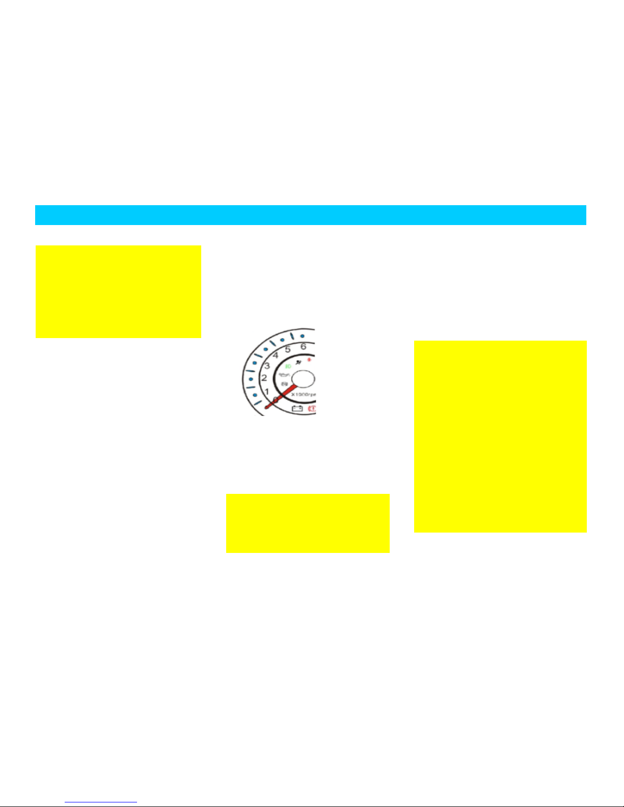
Attentions should be
paid after the period of
running in:
In the case of driving the vehicle fitted
with engine tachometer, the allowable
maximum revolution of engine is 6,000
r/min in a short time. While shifting gear
manually, the vehicle must be shifted to
the neighboring high gear at latest before
the needle of tachometer is in the red
indicative range.
Engine should be avoided to
operate at unnecessary high
speed. It should be shifted to the high gear
as early as possible in favor of saving fuel
and decreasing operational noise and
helping to reduce environmental pollution.
While in driving, the engine is also
unfavorable with too low revolution. It
should be shifted to the proper gear at
proper time.
With cold engine, whether in NEUTRAL
or running gears, do not let engine work at
maximum revolution state.
A new tire has no optimal adhesive force
when first used. Therefore, a new tire
requires running-in; when traveling in first
100 kilometers, drive slowly and take
extra care and precaution.
New brake lining is also required to run in.
In view of the fact that within the driving
of first 200 km, brake cannot produce
ideal friction with slightly bad braking
effect, brake pedal can be depressed with
moderately violent force. In this stage, if
damping-effect is a little poor, increase
pressure on pedal properly. Such case also
applies to each replacement of brake lining
afterwards.
Wheel nuts of new vehicle must be
tightened to the specified torque over
again after driving for 800 km. The torque
value is specified in the chapter of
“Parameters of Specification” of this
manual. Likewise, in the event that wheel
Page 9

BRIEF INTRODUCTION
9
has ever been replaced or wheel nuts have
ever been loosened, they must be
tightened to the specified torque once
again after driving for 800 km.
Person-to-person
service
In order to provide you with better service
and vehicle, the dealer of Chery will
designate a service consultant to serve you.
If you have any problem during use of the
vehicle, please contact your service
consultant and he/she will provide you
with top-quality service.
Page 10
BRIEF INTRODUCTION
10
Inspection Proof at Delivery
This vehicle has passed the delivery inspections in
accordance with the provisions of Chery Automobile Co.,
Ltd. This is to certify that the quality of the vehicle complies
with the technical specifications of Chery Automobile Co.,
Ltd.
Date of delivery:
Seal of Dealer:
Name of owner of the
vehicle (organization)
Address——————————————
Name of the service station in
charge
Person in charge—————————
Page 11
BRIEF INTRODUCTION
11
Documentation of the vehicle
Date of Delivery:
Seal of the dealer
Vehicle Type
VIN code on body
Engine No.
Transmission No.
Page 12
BRIEF INTRODUCTION
12
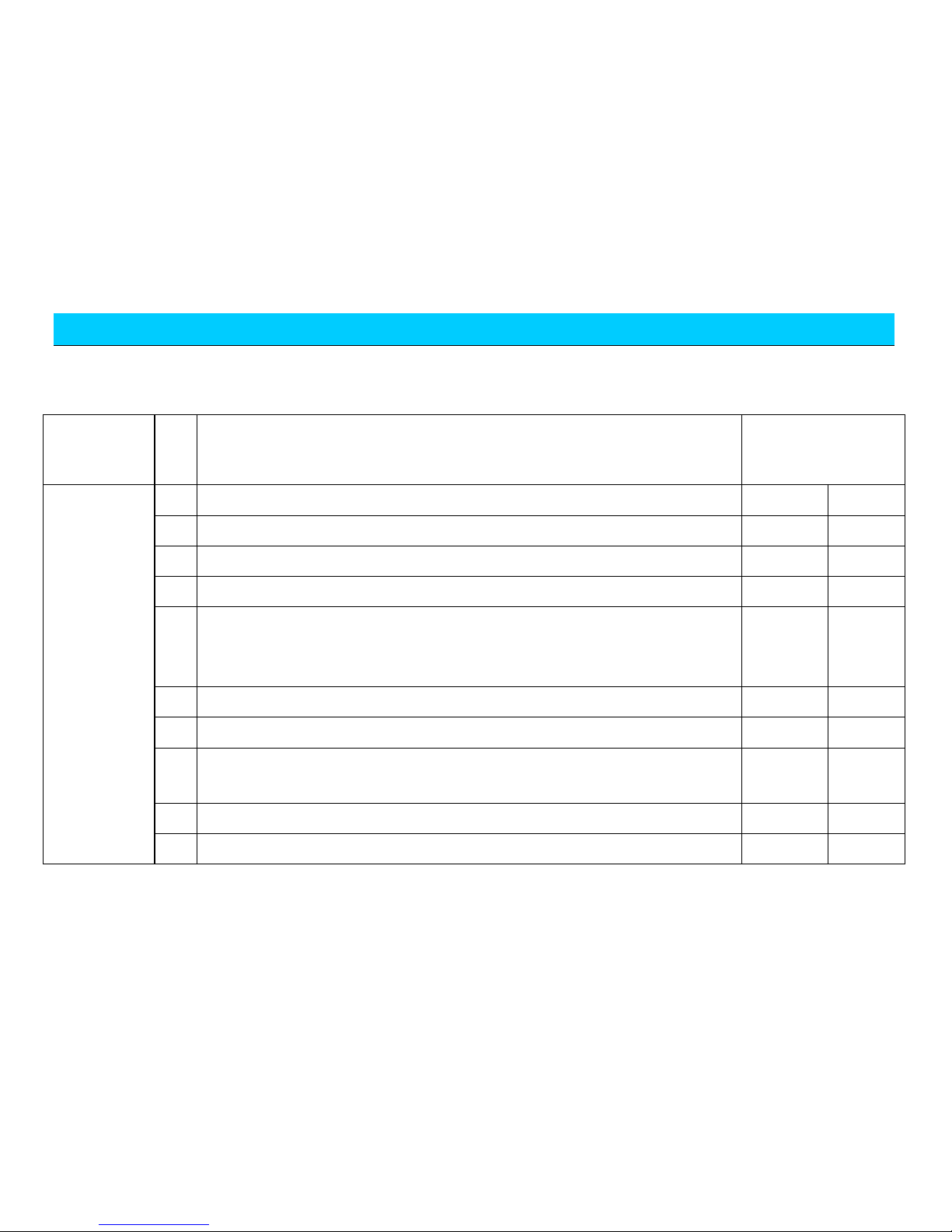
Sales delivery card of Chery vehicle
Category
No
Item
Passed inspections and
made clear?
Performance
of complete
vehicle
1
Engine
Yes □
No □
2
Engine oil, brake fluid, steering fluid, coolant, electrolyte, windshield washer fluid
Yes □
No □
3
Identification of VIN Code, engine No., nameplate etc.
Yes □
No □
4
Lockset, keys and remote controllers of the whole vehicle.
Yes □
No □
5
Complete set of vehicle lights including headlamp, turn signal light, fog light,
combination lamp, interior light, stop light, backup lamp, tail light, reading light, door
light and instrument lamp.
Yes □
No □
6
Glass and body paint surface of the whole vehicle.
Yes □
No □
7
Speedometer, engine tachometer, odometer, water temperature gauge, and fuel gauge.
Yes □
No □
8
Wheel cover, spare tire, driver tools and operating instruction manual of the complete
vehicle.
Yes □
No □
9
Seat belt, seat, cigarette lighter, A/C switch and ventilator, glove box and sun visor.
Yes □
No □
10
Window regulator, rear view mirror, wiper, washer, horn, audio system, and antenna.
Yes □
No □
Page 13
BRIEF INTRODUCTION
13
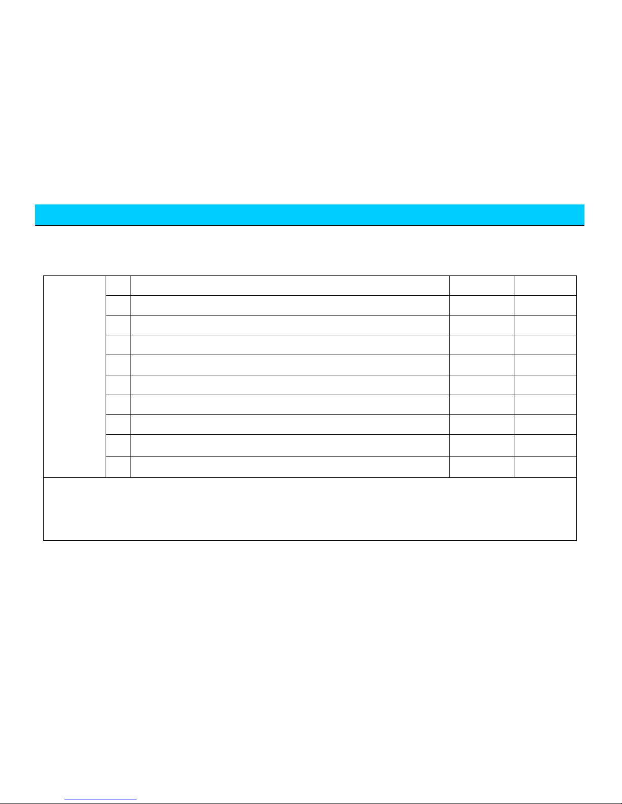
General
knowledge
of use
1
No.93 gasoline.
Yes □
No □
Normal operation in run-in period.
Yes □
No □
Operation of complete set of vehicle lights.
Yes □
No □
Meanings of warning light.
Yes □
No □
Correct maintenance time and mileage.
Yes □
No □
Items of vehicle maintenance in winter/summer.
Yes □
No □
Proper understanding of cooling system and use of coolant.
Yes □
No □
Correct operation of A/C.
Yes □
No □
Precautions while starting vehicle.
Yes □
No □
Correct operation of audio.
Yes □
No □
Signature of the sales person: Date: Signature of the customer: Date:
Page 14

BRIEF INTRODUCTION
14
“Person to Person” Consultant Service
Card (Service Station)
Name of Customer: Date of Purchase:
Dealer of Sale Service: Model:
VIN No. of Vehicle:
Followings are to be confirmed by customers.
I. Confirmation of matters related to the delivery of vehicle (In the
case of “Yes”, mark with “√”, otherwise with “×”).
□ Basic usage of the vehicle has been introduced; on-site delivery
inspections have been performed and the results are acceptable.
□ Have introduced the policy of warranty.
□ Have introduced the precautions of driving.
□ Have introduced the importance of regular maintenance on
vehicle and maintenance interval of time/mileage.
□ Have informed the importance of maintaining and servicing
vehicle at the Chery authorized service station.
□ Have delivered the user’s manual and reminded the customer to
read it.
□ Have informed the function and operational method of the
hotline of Chery customer service.
II. Description of “Person-to-Person” advisory service mode (In
the case of “Yes”, mark with “√”, otherwise with “×”).
□ If the customer has problem and demand, just contacts the
service advisor instead of other persons.
□ The service advisor is the only person designated by the service
station to communicate with customers.
□ One customer just accepts services from one responsible service
advisor: “Person-to-Person”.
In the event that the customer is not satisfied with the service
advisor, he can choose another service advisor.
III. Description of main job of service advisor (In the case of
“available”, mark with “√”, otherwise with “×”).
□ Reception of maintenance service
□ Acceptance of complaint
□ Follow-up visit reminder of scheduled maintenance
□ Solutions to consultations in service/maintenance
Page 15

BRIEF INTRODUCTION
15
□ Regular greeting follow-up visit
□ Acceptance of reserve of service/maintenance
□ Follow-up visit reminder of service activity
□ Reminder/acceptance of yearly audit
□ Greeting on important festival
□ Other affairs the customer demands
IV. Relationship establishment of “Person-to-Person” advisory
service
Business car of the service consultant
Signature of the customer/date:
Signature of the service consultant/date:
First document For filing of the service station
Page 16

BRIEF INTRODUCTION
16
“Person to Person” Consultant Service
Card (Customer)
Name of Customer: Date of Purchase:
Dealer of Sale Service: Model:
VIN No. of Vehicle:
Followings are to be confirmed by customers.
I. Confirmation of matters related to the delivery of vehicle (In the
case of “Yes”, mark with “√”, otherwise with “×”).
□ Basic usage of the vehicle has been introduced; on-site delivery
inspections have been performed and the results are acceptable.
□ Have introduced the policy of warranty.
□ Have introduced the precautions of driving.
□ Have introduced the importance of regular maintenance on
vehicle and maintenance interval of time/mileage.
□ Have informed the importance of maintaining and servicing
vehicle at the Chery authorized service station.
□ Have delivered the user’s manual and reminded the customer to
read it.
□ Have informed the function and operational method of the
hotline of Chery customer service.
II. Description of “Person-to-Person” advisory service mode (In
the case of “Yes”, mark with “√”, otherwise with “×”).
□ If the customer has problem and demand, just contacts the
service advisor instead of other persons.
□ The service advisor is the only person designated by the service
station to communicate with customers.
□ One customer just accepts services from one responsible service
advisor: “Person-to-Person”.
In the event that the customer is not satisfied with the service
advisor, he can choose another service advisor.
III. Description of main job of service advisor (In the case of
“available”, mark with “√”, otherwise with “×”).
□ Reception of maintenance service
□ Acceptance of complaint
□ Follow-up visit reminder of scheduled maintenance
□ Solutions to consultations in service/maintenance
Second document For filing of the customer
Page 17

BRIEF INTRODUCTION
17
□ Regular greeting follow-up visit □ Acceptance of reserve of
service/maintenance
□ Follow-up visit reminder of service activity □
Reminder/acceptance of yearly audit
□ Greeting on important festival
□ Other affairs the customer demands
IV. Relationship establishment of “Person-to-Person” advisory
service
Business car of the service consultant
Signature of the customer/date:
Signature of the service consultant/date:
Second document For filing of the customer
Page 18
BRIEF INTRODUCTION
18
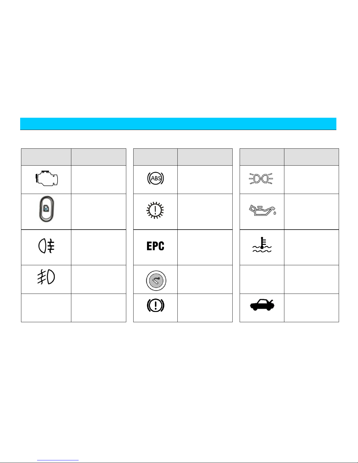
Descriptions of common symbols on the vehicle
Code
Definition
Code
Definition
Code
Definition
Engine failure
warning light
ABS trouble warning
light
Indicator light of
position lamp
Disabled button of
window regulator
switch
Transmission trouble
warning light
Low oil pressure
warning light
Indicator light of rear
fog lamp
Electronic throttle
trouble warning light
Over-high coolant
temperature warning
light
Indicator light of
front fog lamp
Cigarette Lighter
Tire pressure
warning light
A/C
A/C system switch
Brake system trouble
warning light
Opening switch of
luggage boot door
Page 19
BRIEF INTRODUCTION
19
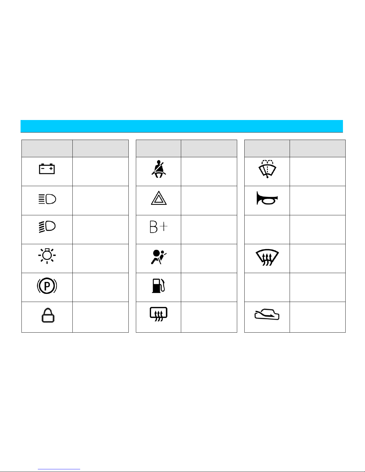
Code
Definition
Code
Definition
Code
Definition
Battery charging
indicator light
Seat belt reminder
warning light
Windshield washing
Indicator light of
high beam
Hazard warning light
Mark of horn button
Indicator light of low
beam
Battery positive
Distance display of
reversing radar
Headlamp switch
Air bag trouble
warning light
Windshield
defrost/demist
Parking brake
indicator lamp
Low fuel level
warning light
Left turn signal light
Lock
Heating rear
windshield
Outside air
circulation
Page 20
BRIEF INTRODUCTION
20
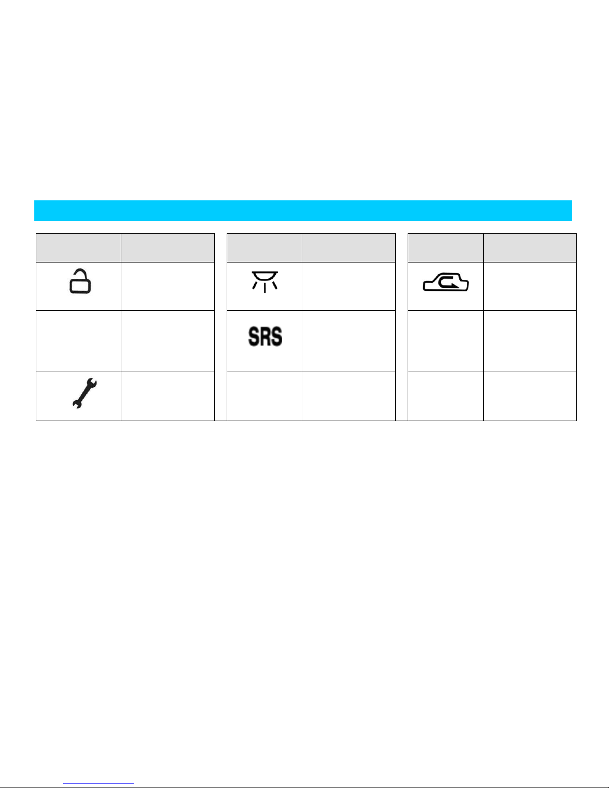
Code
Definition
Code
Definition
Code
Definition
Unlock
Interior lamp switch
Inside air circulation
Door closing
reminder warning
light
Air Bag
Vehicle maintenance
warning light
Right turn indicator
light
Page 21

INTRODUCTION OF DRIVING
CHAPTER TWO INTRODUCTION OF DRIVING
Page 22

INTRODUCTION OF DRIVING
The engine’s long high-speed
racing could cause the engine and its
exhaust system to overheat and has
chance to cause fire and other
damages. Therefore, do not park on
the ground with hay or other dry
The tail gas exhausted from
the vehicle is toxic, so, do not start a
car long in an in-closed garage or
other closed places. Be sure to open
the door of the garage before starts
the engine. See “Beware of the Car’s
Exhaust Fume” for more information.
Start
PREPARATION
BEFORE STARTING
The engine’s starting is controlled by an
electric control system.
When starting an electronic injection
engine, do not push down the accelerator
pedal before and during the starting. Use
the accelerator pedal only when it is
difficult to start the engine. For more
information about the car’s starting, see
“Starting” in this chapter.
SAFETY NOTICE
The engine’s idle speed RPM is controlled
by an electric control system. The engine
starts with a higher idle speed RPM so as
to raise its temperature. The idle speed
RPM should automatically fall after the
engine reaches a proper temperature.
Deliver the car to Chery Authorized
Service Station for repair if the idle speed
RPM could not fall automatically. Do not
let engine run for more than 10 minutes at
a speed higher than specified idle speed.
MATTERS
CONCERNED
BEFORE STARTING
YOUR VEHICLE
Page 23

INTRODUCTION OF DRIVING
Be sure that all passengers tie the
seat belts properly. See the chapter
“Seats and Safety Device” for more
information about seat belt and its
proper usage.
Be sure that the headlight and other
electrical accessories are OFF.
Make sure handle of hand brake has
been pulled up.
Be sure that the selector lever is in
NEUTRAL.
Turn ignition switch to the “Ⅱ”
position other than the “III”.
If there exists resistance turning the key,
turn the steering wheel left and right until
the key could turn freely. This occurs
probably due to the following reasons:
The front wheel deflexion.
The front wheel hits the curb.
The steering wheel is turned when
getting into or out of the car. (the
steering wheel self-locks).
Be sure that the warning light on the
dashboard shine short time while
turning on the ignition key. If not,
deliver the car to Chery Authorized
Service Station for repair.
The warning light will not shine with the
driver’s seat belt fastened before turning
on the ignition key.
THE ENGINE’S
STARTING
1. Turn the ignition switch to the “Ⅲ”
position without stepping on the
accelerator pedal; release the key
immediately after the engine starts,
then the key will return to the “II”
position.
2. If ambient temperature is above
-12C and the engine fails to start
within 5 seconds for the first start,
turn the key to the “B” position and
wait 10 seconds before another try.
3. If the temperature is below -12C
and the engine fails to start within 15
seconds for the first start, turn the
key to the “B” position and wait 10
seconds before another try. If the
engine fails to start in successive two
tries, push accelerator pedal to floor
and hold, then turn the key to the
“Ⅲ” position. After the engine starts,
release the key, and then release the
accelerator pedal slowly as the
engine's RPM rises.
4. Run in idle speed a few seconds
after the engine starts, and then push
Page 24
INTRODUCTION OF DRIVING
If it smells peculiar like
exhaust fume inside the car, ask the
personnel from Chery Authorized
Service Station to repair the car. Do
not continue to drive because the
exhaust fume contains poisonous
content that may endanger life.
down the clutch, shift to the running
gear, release the hand brake to get
ready to run.
5. The ambient temperature conditions
applicable to normal start of the
engine is -25℃-40℃ (when the
ambient temperature is beyond this
range, other abnormal situations may
appear).
BEWARE OF THE
CAR’S EXHAUST
FUME
Though the vehicle’s exhaust fume only
has small toxicity, it contains carbon
monoxide, the poison which you must
beware of. Some compositions in the
engine’s exhaust gas and chemicals
contained in or generated by some
automotive parts may be carcinogenic or
cause neonate defects or other genital
system damages.
In the following cases, check exhaust
system and body ventilation system of the
vehicle.
Lift the car to examine and repair it.
The sounds of the exhaustion system
change.
The car is damaged by collision.
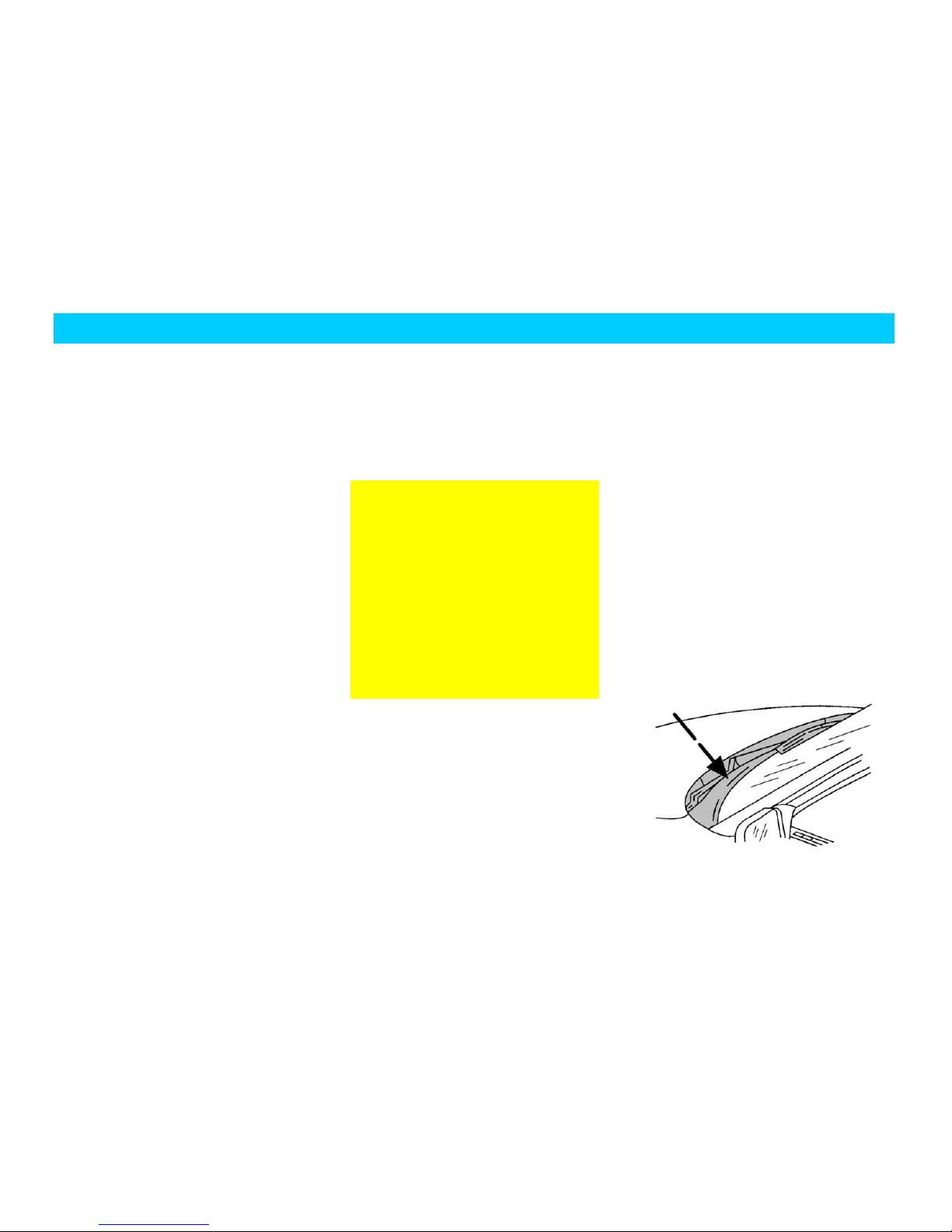
NOTICE OF
VENTILATION
Open the car’s windows with a gap more
than 2.5cm when parking long in idle
speed in an open area. Or use the
ventilation function of the car’s air
conditioning system to let fresh air into the
car.
Air vent
Page 25
INTRODUCTION OF DRIVING
The engine’s temperature will
remain high after you turn off the
ignition switch and the engine stalls, so
let the electronic cooling fan of the
radiator continue to run about 10
minutes. Even if the cooling fan stops,
it may run again suddenly because of
high temperature. Therefore, when
working beside the engine, extra care
must be taken.
Clear away snow, fallen
leaves and other foreign materials
blocking at air inlet to ensure
ventilation effect of the vehicle.
SELF-ADAPTING
ABILITY OF THE
ENGINE’S
CONTROL SYSTEM.
If the battery cable has been removed from
the accumulator, the car may present itself
some abnormal phenomena in the initial
stage of running after the cable be
reconnected. This is normal in that the
engine’s control system is re-studying to
adapt the engine.
CONFINING THE
ENGINE’S RPM
To protect the engine, its RPM is confined
by an electronic unit (ECU).
ENGINE STALL
Release the accelerator pedal. Wait until
the engine’s RPM falls to idle speed, and
then turn off the ignition switch.
Do not turn off the engine immediately
when parking after a long time high-speed
running, and leave the engine continue to
run two minutes at a RPM higher than the
idle speed RPM so that the engine’s
temperature can fall gradually.
Do not push down the
accelerator pedal before turning off
Page 26

INTRODUCTION OF DRIVING
If brake fluid level is found too
low, immediately add brake fluid to
maintain its level between MAX and
MIN and send your vehicle to Chery
Authorized Service Station for
inspection of brake system.
When one braking circuit fails
to work, you need to apply larger force
on the brake pedal when braking and
the stopping distance will also be
longer. Deliver the car to Chery
Authorized Service Station for repair
when this occurs before your journey.
BRAKING
DUAL CIRCUIT
BRAKING SYSTEM
You vehicle is equipped with an X-shape
dual-circuit brake system. In case one of
the two circuits fails, the other circuit can
still maintain effective operation.
LOW BRAKE FLUID
LEVEL ALARM
If the “ ” trouble light on dashboard
constantly lights when ignition switch is
set to the “Ⅱ” position, it indicates a
failure in mechanical part of brake system
or low brake fluid level.
Check the liquid level of the brake fluid at
regular intervals as required.
Page 27

INTRODUCTION OF DRIVING
Be sure to make air flow to
the front brake unblocked if the front
spoiler is mounted on the body,
otherwise, the braking system may
overheat or reduce its braking
efficency due to bad abstraction of
heat.
The brake booster is
controlled by the engine vacuum, and
the unit works only when the engine
OPERATION
DESCRIPTION FOR
THE BRAKING
SYSTEM
It is normal for the braking system to
generate some noises occasionally. But, if
it make sounds like grinding between
metals or screams, the brake discs may
have been heavily worn and need to be
replaced. Now, deliver the car to Chery
Authorized Service Station for repair.
Deliver the car to Chery Authorized
Service Station for repair if there are
consecutive chattering or vibrations being
transferred to the steering wheel when
braking.
A new brake lining must go through a
running-in before reaching its optimal
braking effect. The braking-effect will fall
a little in the initial 200 kilometer. In this
case, apply larger force on the pedal
properly to compensate the braking-effect.
This point also applies to the new brake
lining replaced.
Wear status of brake lining depends
greatly on operating mode and driving
method. For a vehicle mainly used in
urban traffic, the working conditions of its
brake linings is very hard; therefore, be
sure to send your vehicle to a Chery
Authorized Service Station to check the
thickness of the brake linings or replace
them at the specified maintenance
kilometrage.
When running downgrade, shift to a lower
gear timely to make full use of the
engine’s braking action for reducing the
load of the braking system. At this time,
do not keep pushing down the brake pedal
even braking is needed.
Damping brake disc may reduce the
braking efficiency. After driving through
water, rainstorm or car washing, push
brake pedal gently to make brake disc and
brake lining rub to generate heat, which
will evaporate the water and restore the
braking effect.
BRAKE BOOSTER:
Page 28
INTRODUCTION OF DRIVING
Each pedal could be pushed
down to the floor and could restore
fully and move freely.
Though ABS can ensure the
optimal damping-effect, the stopping
distances may vary greatly with
traffic surfaces. ABS can not always
ensure to reduce the stopping
distances on all road surfaces. For
In case the brake booster is unable to work
because of the vehicle’s being towed or
self failure, apply a larger force on the
pedal to compensate the booster’s effect.
Therefore, do not lay foot pad or other
coverings on the floor around the pedal. If
indeed necessary, be sure that the foot pad
laid will not hinder the movement of the
pedal and will not slide itself.
ANTILOCK BRAKE
SYSTEM ABS( )
ABS can avoid the wheel sticking. It can
even make the car hold turning ability
during emergency braking, which allows
you to avoid the obstructions.
ACTIONS OF ABS
ABS only functions during service braking.
When braking, the brake pedal’s pulsating
accompanying with noises indicates that
ABS is working, and the pulsating and
noises are normal. At this time, do not
release the brake pedal.
UTILIZING ABS TO
BRAKE
Keep pushing down the brake pedal in full
force in emergency may start ABS
immediately, which allow you to control
the turning and avoid the obstructions
where enough space is available.
We recommend you firstly getting familiar
with this brake technique, but avoid taking
any unnecessary risk.
Page 29
INTRODUCTION OF DRIVING
During traveling, if ABS
warning lamp is found to light, it
indicates a failure in circuit part of
SELF-CHECKING OF
ABS
ABS will perform self-checking after the
vehicle starts. It is normal that you can
hear some mechanical noises during this
course.
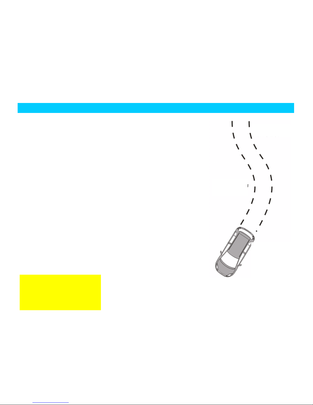
Important principle in
utilizing ABS to brake
1. Push down brake
pedal at full tilt and
hold.
2. Turn steering wheel
to round the obstacle.
No matter how violent
the braking is, you can
always maintain
operating control
performance during
turning.
Page 30
INTRODUCTION OF DRIVING
Pull up the handle of hand
brake before leaving the car.
HAND BRAKE
After parking, strain the hand brake
upwards to prevent car sliding due to
neglect.
When pulling up hand brake with ignition
switch turned on, the parking brake
indicator light will light. To apply hand
brake, pull its handle up.
To release hand brake, slightly pull its
handle, press down the release button
under the handle and just push the button
down.
The hand brake applies action on the rear
wheel. Push down the brake pedal while
pulling up the hand brake, which will
facilitate the hand brake’s pulling up.
OPERATIONS OF MANUAL
TRANSMISSION
Methods and notices for use/operation:
When shifting gear, fully apply
clutch pedal and then control shift
lever to shift gear after separating
transmission input shaft from engine
power.
When the vehicle runs downhill or
makes a turn, please shift into some
low gear and it is not allowed that
the vehicle coasts under the
condition that the clutch is released.
When transmission shifts from lower
gear to higher gear, do not perform
gear-jumping, otherwise life of
synchronizer will be shortened.
No flap (i.e. rapid push and release)
is allowed for gear shifting and you
shall hold the shift lever all the time
during the procedure so as to
considerably reduce the sliding
friction time of synchronizer locking
ring as well as their wear and tear.
During the driving, you shall not put
your hand onto the gearshift lever;
otherwise it will cause the shift forks
to be rapidly worn.
If the transmission sends out any
abnormal sound, it is obviously
Handle of hand brake
Seat
Seat
Page 31

INTRODUCTION OF DRIVING
It is not allowed to
disconnect the high voltage lead from
the coil to check the working status
of the engine or observe the spark
jump status of the spark plug by the
method of fuesingle cylinder,
otherwise, it may spoil the three way
catalytic converter.
difficult to control the shift lever, etc.
during its use, you shall immediately
stop and check the vehicle. You can
drive again only after the
troubleshooting.
TURNING
To avoid damages to power steering
system:
Do not stick the steering wheel (turn
to the left or right dead point) more
than 10 seconds when the engine is
running.
Fill up the power steering fluid once
its liquid level is under MIN mark in its
reservoir. Do not drive the car before
filling up.
The car will lose the turning booster force
when the power steering system breaks
down or the engine stalls. You can still
turn the steering wheel, but larger force is
required.
Check the following if the car wanders or
swings:
If pressures of the front two tires are
identical
If the wearing status of the tires is
uniform
If some suspension components are
loose or wearing
If some turning parts are loose or
wearing
If the tires are positioned properly
DRIVING
THROUGH WATER
If the car needs to drive through water,
drive carefully and slowly especially when
you do not know the water situation. Do
not go on driving if the water may
submerge the wheel hubs.
When driving through water, both the
Page 32

INTRODUCTION OF DRIVING
If the engine keep running,
the three way catalytic converter will
become very hot, therefore, wear on a
protective glove during maintenance
to avoid scald.
car’s traction and braking performance
will fall and the car also may flameout.
If the water enters the intake pipe of the
engine, it will cause great damages to the
engine. In case of deeply driving through
water, the water may enter the
transmission gear from the vent hole and
spoil the transmission.
Be sure to drive slowly and slightly push
down the brake pedal several times to
remove the water on the brake after
driving through water. The water on a
brake will make braking performance of
the brake fall.
THREE WAY
CATALYTIC
CONVERTER
The three-way catalytic converter helps
reduce exhaust gas pollution.
The gasoline engine car is equipped with
narrow-necked filler, which can only
accommodate the compressor gun of
lead-free gasoline.
DRIVING A CAR
EQUIPPED WITH A
THREE WAY
CATALYTIC
CONVERTER
Unleaded gasoline
Page 33

INTRODUCTION OF DRIVING
Drive the car at a lower speed
to the nearest Chery Authorized
Service Station if the engine
mis-ignites or its performance falls
when running. Be sure not to drive at
a high speed.
Avoid any cases that may cause unburned
or partly unburned fuel enters the three
way catalytic converter, especially when
the engine is overheating.
AVOID THE
FOLLOWING CASES:
Run out of fuel.
Unnecessarily start the engine long.
When engine is working, let it run
with one or more spark plugs
removed.
Start the car whose engine is still in
the working temperature by pushing
or towing.
Turn off the ignition switch when
running.
PARKING
Do not park your vehicle on dry tree
leaves or hay. There exists chance of fire
even the engine is turned off because the
exhaust gas will still emit relatively large
heat in a short time.
Be sure to turn off the ignition switch
before leaving the car. Do not let the
engine run with nobody inside the car.
Your car may move by chance to cause
personnel injury or property damage if you
neglect this point.
PROTECTING THE
CHASSIS
Your car is equipped with a heat shield.
Do not apply any painting dressing on the
body of the heat shield, exhaust pipe or
three-way catalytic converter or its
vicinity area. Do not remove the heat
shield.
Page 34

INTRODUCTION OF DRIVING
FUEL
CONSUMPTION
FUEL
CONSUMPTION
DEPENDS ON THE
FOLLOWING
FACTORS:
SPEED AND THE GEAR
SELECTED
The above chart indicates how the fuel
consumption is affected by speed and the
gear selected. keeping in lower gear to
improve the acceleration quality may
obviously cause rise of fuel consumption.
DISTANCE OF
RUN/TEMPERATURE
OF THE ENGINE
Frequently cold starting and short distance
driving may obviously make the fuel
consumption rise.
TRAFFIC AND ROAD
STATUS
Traffic jam, upgrade, many bends and
rough surface will all throw adverse
impact on the fuel consumption.
GOOD DRIVING
HABIT
Forecast the dangers and keep a safe
driving distance with the vehicle in front.
This will not only reduce the fuel
consumption but also the wearing of the
brake and its noises.
LOAD CONDITION OF
THE CAR
Increasing the load of the car may cause
rise of fuel consumption.
Fuel consumption
Driving speed
Page 35

INTRODUCTION OF DRIVING
After parking and turning off
the engine, the radiator fan will
continue to run a period of time
(about 10 minutes) because the
engine is still in a superheating status
and it will stop running until the
engine cools to a certain temperature.
Even so, the fan may start suddenly
due to temperature rise of the engine
compartment caused by temperature
of outside surroundings (under
isolation or in high temperature
region). Therefore, be careful when
working in the engine compartment
to avoid any accidents!
TECHNICAL
CONDITION OF THE
CAR
Under the pressure of tire or the poor
maintenance of the engine, the car will
also cause the fuel consumption.
KEY POINTS FOR
FUEL-SAVING
DRIVING AND
ENVIRONMENTAL
PROTECTING:
Drive with fuel-saving and use
additional electric load only when
necessary.
Start without pre-warming the car.
Push down the accelerator pedal
smoothly.
Shift to the next higher gear as soon
as possible to obtain a higher engine
revolution.
Forecast the traffic status.
Close the air conditioner and the
heating unit for rear windshield
immediately when unnecessary.
Regularly check or adjust tire
pressure.
Perform scheduled maintenance and
preferably ask the professionals from
Chery Authorized Service Station do
it for you.
RADIATOR FAN
The radiator fan is an electrodynamic one
and its working status is controlled by
ECU of the engine. The switch will
automatically turn on the fan circuit when
the coolant or engine compartment reaches
a certain temperature.
Page 36

INTRODUCTION OF DRIVING
Explanation:
If the fan fails to run after the temperature
of the coolant reaches the starting
temperature of the fan, check the fuse of
the fan for blowing out, and replace the
fuse if necessary. If this does not work,
find out other causes.
The RPM of the fan is independent to that
of the engine and shifting to a lower gear
will not increase the cooling effect of the
fan. Therefore, need not to shift to a lower
gear when the engine runs smoothly and
its speed does not fall obviously when
climbing.
Page 37

INTRODUCTION OF FUNCTIONS AND DESCRIPTION OF INDICATIONS OF THE VEHICLE
CHAPTER THREE INTRODUCTION OF
FUNCTIONS AND DESCRIPTION OF
INDICATIONS OF THE VEHICLE
Page 38

INTRODUCTION OF FUNCTIONS AND DESCRIPTION OF INDICATIONS OF THE VEHICLE
Page 39

INTRODUCTION OF FUNCTIONS AND DESCRIPTION OF INDICATIONS OF THE VEHICLE
I. INTRODUCTION
OF FUNCTIONS OF
THE VEHICLE
STEERING WHEEL
LOCK & IGNITION
SWITCH
The operational positions of key for the
combined type steering wheel
lock/ignition switch are detailed in the
following:
“B”-ignition switch is turned off and
steering wheel is locked.
When pulling key out of ignition switch,
lock steering wheel.
To lock the steering wheel, turn it once after
pulling out the key until a click indicating
lockup of the steering wheel is heard.
“I”-unlock position steering system. The
circuits of electrical accessories are turned
on and the small electrical appliances
inside the vehicle such as radio, power
windows and headlamps can be operated,
but ignition system and other main
electrical circuits are power off.
In the event that the key cannot be turned
from LOCK position to this position or
can be done with much efforts, the
steering wheel can be slightly turned back
and forth, thus the steering wheel locking
mechanism can be unlocked.
“II”-ignition circuit is turned on and all
electrical circuits can work. The alarm
lamp and the indicator light will light. This
position is normal for driving and
indispensable to trailing.
“III”-position for starting and ignition.
Starting circuit and ignition circuit are
turned on to start the engine.
With the key at this position, the
headlamps and electrical equipment with
heavy load are all in the condition of open
circuit.
Ignition switch has a built-in anti-restarting
device. Once the engine starts, this device
can prevent starter from starting by error,
thus avoid damage to the starter and
flywheel of the engine.
Page 40

INTRODUCTION OF FUNCTIONS AND DESCRIPTION OF INDICATIONS OF THE VEHICLE
If fail to start, the ignition key must be
turned to position “B” before restart, and
then turn it to this position. After the
engine starts, release your hand and the
key will spring back to the “II” position.
ADJUST STEERING
WHEEL
To drive your car safely and comfortably,
sometimes the height of steering wheel
needs to be adjusted. At this time, pull the
adjusting handle under steering column
cover down to release it, and then the
steering wheel can move up and down.
After the steering wheel has been adjusted
in place, pull the adjusting handle up to
locking position to lock position of the
steering wheel.
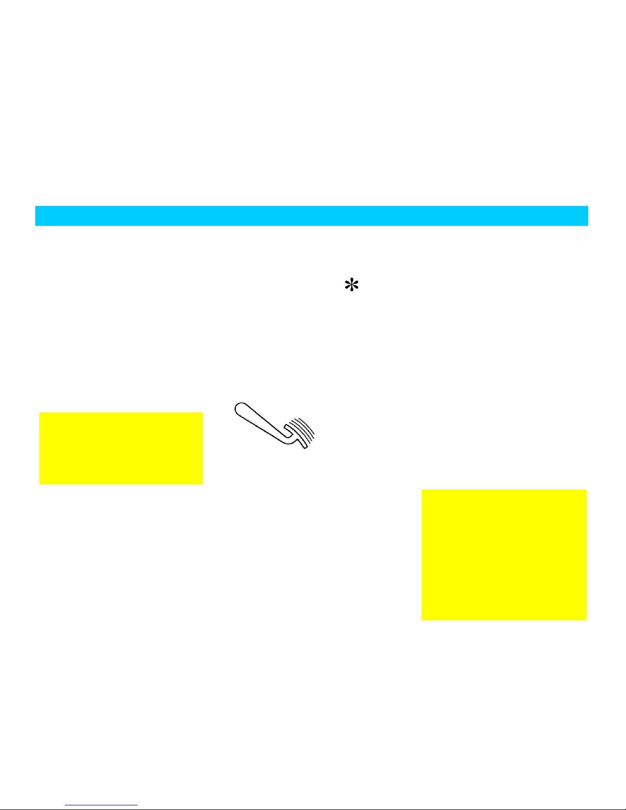
Horn
Push the push-pad marked with “ ” on
the steering wheel down and the horn will
flute immediately. While the ignition
switch is off, the horn can still be
operated.
WINDSHIELD WIPER
& WASHING SYSTEM
Once the engine starts, be
sure to release the key immediately.
Do not stay at the “III” position too
long.
Page 41

INTRODUCTION OF FUNCTIONS AND DESCRIPTION OF INDICATIONS OF THE VEHICLE
Only by placing the ignition switch at ON
position can the wiper motor operate. The
front wiper has four positions; when not in
use, it stops at OFF position.
INTERMITTENT WIPE
Shift wiper switch up once from “OFF”
position to “INT” position.
At intervals, the wiper will scrape on the
windshield for several times.
REGULAR WIPE
Shift wiper switch up twice from “OFF”
position to “LO” position.
HIGH-SPEED WIPE
Shift wiper switch up thrice from “OFF”
position to “HI” position.
WATER-JET SWITCH
In cold season, be sure to
check if wiper blade is frozen to
windshield before using wiper. If
so, be sure to thaw it first be using,
otherwise wiper motor may be
damaged.
Operating wiper with such
obstacles as snow etc. on
windshield may also damage wiper
motor.
Before operating wiper, please clear
obstacles away first.
Do not operate wiper on dry
windshield, otherwise glass may be
scratched and permanent damage
may be made to wiper blade.
Page 42

INTRODUCTION OF FUNCTIONS AND DESCRIPTION OF INDICATIONS OF THE VEHICLE
Pull switch lever towards the steering
wheel and let it stay there; washer fluid
will eject from the ejection nozzle in front
of the windshield, meanwhile, the wiper
will act; after the switch lever is released,
water jet will stop right away but the wiper
will still act for several times.
Operation of the wiper on rear windshield:
turn the white dot on water jet switch to
the “ON” position and the rear wiper will
start to work but will not spray water; then
push the wiper switch forward to its
extreme position and hold, rear ejection
nozzles will spray water at the same time.
In case the white dot on water jet switch is
not at the “ON” position, push the wiper
switch forward to its extreme position and
then the rear wiper ejection nozzles will
also spray water and the wiper will act
consecutively; at this time, let go of the
wiper switch, the ejection nozzles will
stop spraying water and the wiper will
stop after several scrapes.
INTERIOR
REARVIEW
MIRROR
When driving at night, if you want to
reduce glare, turn the adjusting knob
leftwards or rightwards to adjust angle of
rear view mirror. When turning the knob
leftwards, the rear view mirror will turn a
certain angle down; when turning it
rightwards, the rear view mirror will turn a
Turn left
Turn right
Anti-glare knob
Page 43

INTRODUCTION OF FUNCTIONS AND DESCRIPTION OF INDICATIONS OF THE VEHICLE
certain angle up.
Sun visor
The sun visor can be unfastened by
loosening the retaining clip and be turned
to the side window.
The left sun visor can be opened to store
such articles as traveling certificate and
invoices of bridge toll and road toll. After
opened, the right sun visor has a mirror for
your use.
CONTROL SWITCH
ON DOOR
The window control switches on left front
door are respectively the switches for left
front, right front, left rear and right rear
power windows and the safety switch for
rear window
Page 44

INTRODUCTION OF FUNCTIONS AND DESCRIPTION OF INDICATIONS OF THE VEHICLE
REAR SEAT POWER
WINDOW SWITCH
ADJUSTING SWITCH
OF POWER
EXTERIOR REAR
VIEW MIRROR
The power rear view mirror can be
regulated through the adjusting switch at
driver side. The adjusting switch can only
work after ignition switch has been turned
to the “II” position.
The exterior rear view mirror at left side
can be regulated by turning the adjusting
switch counter-clockwise to the “L”
position; the exterior rear view mirror at
right side can be regulated by turning the
adjusting switch clockwise to the “R”
position.
When the control switch is turned left or
right to the proper position, pushing the
switch foreword, backward, leftward and
rightward can respectively adjust the
position of mirror surface upward,
downward, leftward and rightward. The
switch should be turned to the mid
position once more after the proper
adjustment.
If necessary, for example, in a narrow
space, you can pull the exterior rear view
mirror by hand and fold it back for about
90°. To restore it to original position,
directly pull the exterior rear view mirror
outwards for a certain angle and it will
automatically
return.
Page 45

INTRODUCTION OF FUNCTIONS AND DESCRIPTION OF INDICATIONS OF THE VEHICLE
POWER WINDOW
Left Front Door
BACK DOOR
The power window can operate only when
the ignition switch is at ON position.
All windows can be operated through the
window regulator control switches on their
respective door interior trim panels.
The window can be opened or closed by
depressing or raising its control switch.
During the ascending or descending of
window glass, if the switch is released, the
window glass will stay at the current
position.
The window lift control switch has delay
function, namely, it can still operate within
60 seconds after pulling out the key.
The glass switch of each door has
touching function when the door window
is falling, i.e. the glass can automatically
fall to bottom after you touch the falling
switch for 300ms and then let go of it.
The control switches of other three
windows are available on the door trim
The object image in exterior
rear view mirror looks a little smaller
and farther than that of the actual
object. Take care not to overestimate
actual distance of the object.
Rear power window switch
Left rear window
switch
Left front window
switch
Page 46

INTRODUCTION OF FUNCTIONS AND DESCRIPTION OF INDICATIONS OF THE VEHICLE
When the window is being
closed, take cares! Attention should
be paid to the observation in case
accidents of injury occur.
panel at the driver’s side besides the
control switch of the window at the
driver’s side.
REAR WINDOW
SAFETY SWITCH
There is also a safety switch button on the
lifting control switch for left front door
window glass. Pressing down this button
can disable the power window switches on
right front door and the two rear doors.
Now, only the switch at the driver’s side
can control the opening and closing of its
corresponding window.
ASHTRAY AND
CIGARETTE
LIGHTER
The front ashtray is located in front of the
shift lever on central console; put the
ashtray outwards to use it; to empty the
ashtray, take it out and then dump the offal
into a garbage can. The rear ashtray is
located behind handle of hand brake on
auxiliary instrument desk.
The cigarette lighter is located exactly
above the ashtray; to use the cigarette
lighter, press it in and wait for it to
automatically eject.
Rear row
ashtray
Cigarette lighter
Front row ashtray
Page 47

INTRODUCTION OF FUNCTIONS AND DESCRIPTION OF INDICATIONS OF THE VEHICLE
The rear row ashtray can be directly taken
out upwards at full tilt; after the ashtray is
taken out, its saddle bore can serve as a
cup holder.
CUP HOLDER
The cup holder is located between A/C
control panel and cigarette lighter.
To open the cup holder, press it down and
then release; to hide the cup holder in the
central console, press it down to bottom
and then release.
LIGHTING
CONTROL
While operating the following lighting
equipment, please abide by relevant traffic
regulations.
Headlamp switch
“OFF”-exterior lamps are turned off.
Side Light:
When headlamp switch on combination switch
is turned to the “I” position, i.e. the “Small
Light” position, front and rear position lamps
and the license plate lamp will be turned on at
the same time.
Noctilucence adjustment:
After small light is turned on, the
noctilucent illumination for instruments,
audio, A/C and switches will lights; by
operating the backlight adjusting switch “
“, brightness of interior backlight
can be adjusted.
Low beam light:
When headlamp switch on combination switch
is turned to the “II” position, i.e. the “Low
Beam Light” position, the low beam light will
light.
The cigarette lighter can
not stay at inserted state long so as
to avoid occurrence of hazard. If any
child is left inside the vehicle alone,
take the cigarette lighter away.
Page 48

INTRODUCTION OF FUNCTIONS AND DESCRIPTION OF INDICATIONS OF THE VEHICLE
Switch between High
Beam/Low Beam of
Headlamp
When headlamp switch is at the “Low
Beam Light” position, i.e. the low beam
light is turned on, pull the handle forward
to get over the stress point and shift in
high beam. When high beam is turned on,
the high beam indicator light in the
instrument will also light. Moving the
handle towards the steering wheel to its
original position can return to the low
beam lamp.
FLASHING OF
HEADLAMP
During driving, if it is necessary to flash
the headlamp, just moving the handle
towards the steering wheel to the resistant
point, and then release the handle to make
it auto return. Repeating this operation can
flash the headlamp continuously.
Low Beam Electric
Control Switch ( )
It locates at right side of fog lamp switch;
through the adjusting knob, height of light
beam of low beam light can be controlled.
There are four figures-“0, 1, 2, 3” on the
knob; while dialing from 0 to 3 in turn,
light beam of the low beam light will
become lower and lower. Note that you
should dial one figure at intervals of 1
minute or so when using. If you dial too
quickly, the electric control switch may
not work.
Front and Rear Fog
Lamp Switches
Page 49

INTRODUCTION OF FUNCTIONS AND DESCRIPTION OF INDICATIONS OF THE VEHICLE
Front fog lamp switch and rear fog lamp
switch locate on the instrument desk at
lower left of the dashboard; when
headlamp switch is at the “I” position or
“II” position, push the knob down for one
grid, the front fog lamp will be turned on
first and it will light, meanwhile, the icon
of front fog lamp will also light. Push the
knob further down for one grid, the rear
fog lamp will be turned on, meanwhile,
the front fog lamp will also light.
What should be reminded of is: to turn on
the front fog lamp, be sure to turn on
headlamp switch first (at the “I” position
or the “II” position). Front fog lamp must
be turned on first before turning on rear
fog lamp.
When front fog lamp lights, the indicator
light “ ” in the instrument will also
light.
Generally, the front fog lamp is used only
in such cases when visibility is badly
affected, for example, in foggy, snowy or
rainy days.
When rear fog lamp is turned on, the
indicator lights “ ” and “ ” in the
instrument will light at the same time.
Considering the rear fog light dazzles
strongly, operating this light is allowed
only under the condition of much low
visibility.
Turning Signal Lamp
Only with the ignition switch on can the
turn signal light works.
Left turn signal light-pull the handle down
Right turn signal light-pull the handle up
When the turn signal light is on, its turn
signal indicator light in the instrument will
flash together with it.
Interior Front Ceiling
Lamp
Page 50

INTRODUCTION OF FUNCTIONS AND DESCRIPTION OF INDICATIONS OF THE VEHICLE
The interior front ceiling lamp is located
on the middlemost roof of cabin.
Press the button “ ” down and the left
reading lamp will light.
Press the button “ ” down and the right
reading lamp will light. When the switch
“ ” is turned from neutral
position to the right, the interior lamp at
right will light. If it is turned to the left,
when one vehicle door is opened, this
lamp will light; when the door is closed,
the lamp has delay function and it will go
out after 8 seconds. When any of doors of
the vehicle is opened, this lamp will
constantly light. When the door is properly
closed, the lamp will go out after 8
seconds. When using a remote controller
to lock and unlock at this position, this
function is also available.
TRUNK LAMP
Uncovering the trunk will turn on this
light which is not under control of the
ignition switch. After parking, please
notice to cover the trunk properly.
Hazard Warning Light
Switch
The triangle in the figure represents the
hazard warning light switch.
This switch locates on central console of
instrument between DVD screen and A/C
vent.
The hazard-warning switch is only for use
under emergence; it can warn the
following vehicles of a failure or a
dangerous condition. Pressing this switch
down can turn on or turn off the hazard
warning light. The hazard warning light
can still function even if ignition switch is
turned off.
After the warning light is turned on, the
indicator light on the switch (yellow zone)
will flash. At the same time, left and right
Page 51

INTRODUCTION OF FUNCTIONS AND DESCRIPTION OF INDICATIONS OF THE VEHICLE
direction indicator lamps on the
combination instrument will also light.
Braking Lamp
When brake pedal is pushed down, brake
lamp will immediately light. Release the
brake pedal and the brake lamp will go
out.
REVERSE LAMPS
With the ignition switch on, the backup
lamp is on when the vehicle is in the
reverse gear. The light goes out when the
ignition switch is off or the vehicle is
changed to other gears.
Reversing Radar Set
( )The vertical detection distance of
this reversing radar is within a range of 1m
while its right-and-left horizontal detection
distance is within a range of 2.8m.
The rearward detection distance of probe
is within a range of 1.5m from it.
As shown in the figure:
This apparatus includes a combination of a
display and a buzzer, which locates inside
the vehicle behind the high position brake
lamp.
When shifting in reverse gear, the
reversing radar will automatically start up
to detect obstacles. At this time, the
figures “88” will be seen to light on the
display through inside rear view mirror,
meanwhile, a chirping will be heard.
In case any obstacle appears within the
detection range, when it is only 1.5m from
the probe, the figure “1.5” will be seen to
appear on the display through the rear
view mirror, which indicates that the
obstacle is only 1.5m from the vehicle tail;
when further backing up the vehicle, the
figures “1.4, 1.3, 1.2, 1.1, 1.0, 0.9, 0.8, 0.7,
0.6. 0.5, 0.4” will appear on the display.
When the distance is between 1.5m and
Detection sketch map
Sketch map of vertical detection range
Sketch map of horizontal detection range
Unit: cm
Display
Status of left obstacle
Status of right obstacle
Page 52

INTRODUCTION OF FUNCTIONS AND DESCRIPTION OF INDICATIONS OF THE VEHICLE
0.9m, the continuous alarm sound similar
to a whistle will be heard. When the
distance is between 0.8 and 0.6m, a
pressing alarm sound will be heard; when
the distance is between 0.6 and 0.4m, the
alarm sound will be more pressing than
ever. If further backing up the vehicle, the
English letter “P” will be seen to appear
through the rear view mirror and the alarm
sound will become more and more
pressing, which reminds the driver that
there is an obstacle behind only less than
0.4m from the vehicle tail and he/she
should stop safely.
Tip: the button on the buzzer of the
reversing radar can be used to adjust
volume of the buzzer.
Note: when backing up, it is safe to
maintain driving speed under 5km/h.
Method
of
alarm
Range of
alarm
Alarm sound
First
stage
1.49m~0.9m
Buzzer sounds for 40ms and
then stops for 500ms.
Second
stage
0.89m~0.6m
Buzzer sounds for 80ms and
then stops for 300ms.
Third
stage
0.59m~0.3m
Buzzer sounds for 380ms and
then stops for 120ms.
Fourth
stage
<0.3m
Buzzer constantly sounds.
The object that the probe of the reversing
radar senses is the one most close to it.
Note that the bumper on a vehicle that has
high body may not be sensed.
Due to modifications in specifications, the
content in this manual may disagree with
actual vehicles, in which case, we thank
for your understanding.
Use a cloth to wipe or use water (low
pressure water) to wash off the snow or
mud adhered to surface of probe of the
reversing radar.
Sound alarm
Page 53

INTRODUCTION OF FUNCTIONS AND DESCRIPTION OF INDICATIONS OF THE VEHICLE
In the event that the alarm sound is not
given off even if the probe approaches the
obstacle, the following points should be
checked:
Whether snow or mud adheres to the
surface of radar probe or not?
Whether the surface of radar probe is
frozen or not?
Whether the car is not operated for a
long period during hot or cold
season or not?
If the above points are not available,
please drive the car to the authorized
CHERY service station for check and
repair.
In the case of the following instances,
the alarm sound is not given off even if
the radar probe approaches the obstacle,
attention should be paid to them:
The high pressure water flow
from a hydraulic giant or similar or
larger external force may result in
failure.
The surface of radar probe must
never be pressed, squeezed or
impacted.
The probe of the radar may
not work below -30℃ or above 80℃.
Page 54

INTRODUCTION OF FUNCTIONS AND DESCRIPTION OF INDICATIONS OF THE VEHICLE
Thin objects like steel wire, rope,
fence and etc.
Low and short objects such as rocks
etc.
Soft objects easy to absorb
ultrasonic like snow, cotton, sponge
etc.
Frozen water drops existed on the
surface of radar probe.
Snow or mud is adhered onto probe
of the reversing radar and the probe
is covered.
In the case of the following instances,
alarm sound may be given off owning to
the wrong sense.
Horn sound of other cars, sound of
Page 55

INTRODUCTION OF FUNCTIONS AND DESCRIPTION OF INDICATIONS OF THE VEHICLE
motorcycle engine, brake air sound
etc. adjacent to the radar probe.
Driving in the jelly-shaped snow or
rain
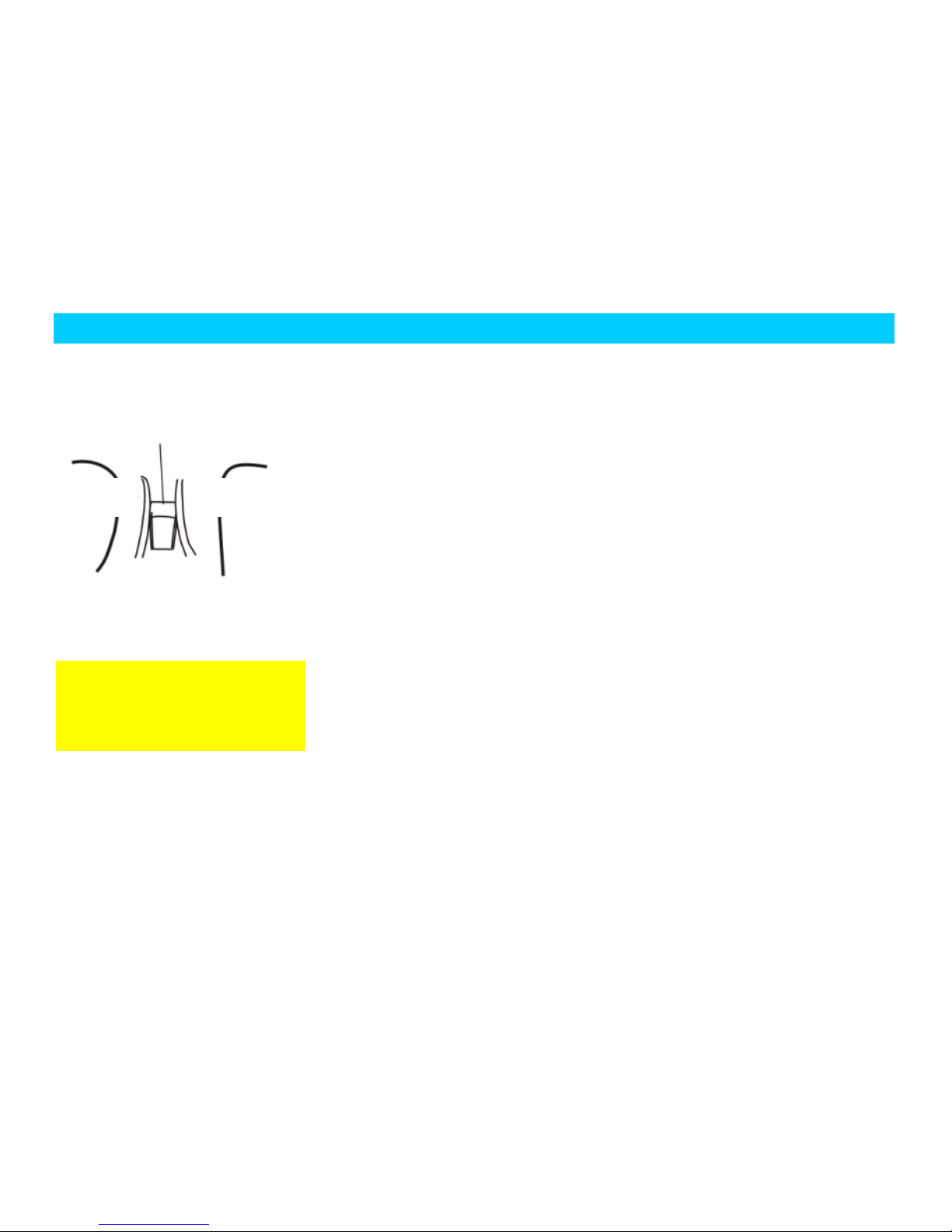
In consideration of the form of
obstacle, the radar may not give off
alarm sound to the objects difficult
to reflect the ultrasonic, shown in the
following figure.
Not give off alarm sound to
objects without the sensing range.
When there are several obstacles, the
probe of the reversing radar only
reports the closest one. When the
vehicle is moving, note that the probe
of the reversing radar at the other side
may approach to other obstacles.
Stud
Thin tree
Corrugated paper
Bicycle tire
Angle
section
Foot stone
Page 56

INTRODUCTION OF FUNCTIONS AND DESCRIPTION OF INDICATIONS OF THE VEHICLE
Audio Panel ( )
Note: if the audio system equipped on this vehicle is none of the following ones, please carefully read the operating instruction manual for
the audio system that comes with the vehicle.
Page 57

INTRODUCTION OF FUNCTIONS AND DESCRIPTION OF INDICATIONS OF THE VEHICLE
Description of Panel
1. In-and-out cartridge key
2. Brightness shortcut key
3. Selecting/initializing settings key
4. Mute key
5. Power supply switch button + volume
adjusting knob
6.1 Play/pause/preset station 1
6.2 Stop/preset station 2
6.3 Random play/preset station 3
6.4 Repeated play/preset station 4
6.5 Voice switch/preset station 5
6.6 Caption switch/preset station 6
6.7 Clock display key
7. Reset function
8.1 Confirmation function
8.2 Left and right direction keys
8.3 Up and down direction keys
9. DVD/radio system switch
10. AM/FM band switch
11. Searching stations and automatic
save/pre-play key
12. Searching stations and manual
save/CD pre-play key
Method of Operation
1. :Open/Close
This key is the in-and-out cartridge key for
DVD disc.
2. : Shortcut key for brightness
This key is the shortcut key for brightness;
pressing it briefly enables normal
brightness/shutting off screen switch
function.
3. SEL: Selecting/initializing settings key
Pressing briefly enables selecting settings
function and the settings will recurrently
switch among Sound Effects, Bass, Treble,
Left-and-Right Balance, Front-and-Rear
Balance, Brightness, Chroma, Contrast,
Screen Mode and Logic; the settings can
be adjusted through volume knob.
Pressing and holding for 0.7 second
enables initializing settings function.
Setting value of system clock can be
adjusted through volume knob.
4. MUTE: Mute key
Mute key for mute of radio or DVD.
5. : :Power supply switch button
+ volume adjusting knob
Please read this chapter
referring to “Audio Panel” and
“Description of Panel”.
Page 58

INTRODUCTION OF FUNCTIONS AND DESCRIPTION OF INDICATIONS OF THE VEHICLE
Turn it counter-clockwise to decrease
volume and clockwise to increase volume.
Press the button down to turn on or turn
off power supply of audio system.
6.1 ( ): Play/pause/preset station
1
Under radio state, pressing it briefly
enables the function of jumping to the first
preset station; under radio state, pressing it
and holding for 0.7 second enables the
function of saving current station to the
first preset station.
Under DVD state, pressing it briefly
enables the function of play/pause.
6.2 (2/■): Stop/preset station 2
Under radio state, pressing it briefly
enables the function of jumping to the
second preset station; under radio state,
pressing it and holding for 0.7 second
enables the function of saving current
station to the first preset station.
Under DVD state, pressing it briefly
enables the function of stop.
6.3 (3/RDM): Random play/preset station
3
Under radio state, pressing it briefly
enables the function of jumping to the
third preset station; under radio state,
pressing it and holding for 0.7 second
enables the function of saving current
station to the first preset station.
Under DVD state, pressing it briefly
enables the function of random play.
6.4 (4/RPT): Repeated play/preset station
4
Under radio state, pressing it briefly
enables the function of jumping to the
fourth preset station; under radio state,
pressing it and holding for 0.7 second
enables the function of saving current
station to the first preset station.
Under DVD state, pressing it briefly
enables the function of repeated play.
6.5 (5/AUD): Voice switch/preset station 5
Under radio state, pressing it briefly
enables the function of jumping to the fifth
preset station; under radio state, pressing it
and holding for 0.7 second enables the
function of saving current station to the
first preset station.
Under DVD state, pressing it briefly
enables the function of voice switch.
6.6 (6/SUBT): Caption switch/preset
station 6
Under radio state, pressing it briefly
enables the function of jumping to the
sixth preset station; under radio state,
pressing it and holding for 0.7 second
enables the function of saving current
station to the first preset station..
Page 59

INTRODUCTION OF FUNCTIONS AND DESCRIPTION OF INDICATIONS OF THE VEHICLE
Under DVD state, pressing it briefly
enables the function of caption switch.
6.7 DISP: Clock display key
Press the DISP key down to display
system clock.
7. RESET: Reset function
Under any state, when you want to restore
the machine to its initial state, just press
RESET key down using an object with
thin tip.
8.1 (ENTER): Confirmation key
The key for confirmation.
8.2 : Left and right direction keys
Under radio state, pressing it briefly
enables the function of rearward/forward
manual station search. Under radio state,
pressing it and holding for 0.7 second
enables the function of rearward/forward
automatic station search.
Under DVD Play state, pressing it briefly
enables the function of fast reverse/fast
forward; under other states, this enables
the function of left/right direction key.
Under DVD Play state, pressing it and
holding for 0.7 second enables the
function of previous/next track; under
other states, this enables the function of
left/right direction key.
8.3 ▼▲: Up and down direction keys
Up direction key and down direction key.
9. SRC: DVD/radio system switch
This is a function select key; when SRC
key is pressed down, if the system is under
AM or FM state, it will switch to DVD
state.
If the system is just under DVD state, it
will switch to radio state.
10. BAND: AM/FM band switch
This is a function select key; under radio
state, press it to switch in the order of
FM1→FM2→FM3→AM1→AM2.
11. AS/PS: Searching stations and
automatic save/pre-play key
Under radio state, pressing it briefly
enables AS function; the system will
search the whole FM/AM band forward
and then save 6 stations of the strongest
signal to save list of FM3/AM3. After
finish of the search, you can browse the
stations in play list. Under radio state,
pressing it and holding for 0.7 second
enables PS function. The system will play
each saved station in current band in turn
for 5 seconds for customers to select and
tune in.
12. SCAN: Searching stations and manual
save/CD pre-play key
Under radio state, press it to search the
whole FM/AM band forward; when
meeting with a station, the system will
Page 60

INTRODUCTION OF FUNCTIONS AND DESCRIPTION OF INDICATIONS OF THE VEHICLE
play for 5 seconds and then continue to
search for other stations. The customers
who are using play function can select to
save the station to corresponding position
in save list; after the station has been
saved, scanning will stop. Under CD Play
state, this key enables the function of disc
browse; the system will play each track in
the CD disc in turn for 10 seconds for
customers to select and listen in.
When using this equipment
long without starting the engine,
beware that the vehicle will be
unable to start after its battery is
exhausted and that life of the battery
may also be cut. Pressing power
supply switch key can turn on or turn
off the machine.
Page 61

INTRODUCTION OF FUNCTIONS AND DESCRIPTION OF INDICATIONS OF THE VEHICLE
Air Conditioner System
VENTILATION
The outside air enters inside of the vehicle via the air inlet at lower right of front windshield. Please keep the air inlet at lower right of front
windshield clear of snow deposit and leaves so as to ensure normal and effective working of heating system and ventilation system.
Page 62

INTRODUCTION OF FUNCTIONS AND DESCRIPTION OF INDICATIONS OF THE VEHICLE
Front windshield defrosting vent
Vents on floor
Vents on instrument
desk
Side defrosting vent
Side defrosting vent
Page 63

INTRODUCTION OF FUNCTIONS AND DESCRIPTION OF INDICATIONS OF THE VEHICLE
AIRFLOW
DISTRIBUTION
The air flow and direction can be adjusted
by means of the button on the air
conditioner control panel and the control
device of side ventilator and central
ventilator.
When adjusting the vent (adjust as
required), note that the blockage in tunnel
and vent will weaken air output.
CENTRAL
VENTILATOR AND
SIDE VENTILATOR
Central vents and side vents are bilaterally
symmetrical.
The switch knob has the function of
opening and closing vent and adjusting
wind direction together; customers can
adjust opening and wind direction at each
vent as required.
MAXIMUM AIRFLOW
Adjusting A/C mode knob to Blow Foot or
Defrosting allows maximum airflow to
flow towards foot pedal area or
windshield.
OFF
ON
Left
Right
Page 64

INTRODUCTION OF FUNCTIONS AND DESCRIPTION OF INDICATIONS OF THE VEHICLE
A/C System Control Panel
1. Cold air/warm air adjusting switch; 2. Blower switch; 3. Airflow distributing switch;
4. Internal/external circulation switch; 5. A/C switch; 6. Rear windshield defroster switch.
Page 65

INTRODUCTION OF FUNCTIONS AND DESCRIPTION OF INDICATIONS OF THE VEHICLE
Cold air/warm air
adjusting switch
It is used to control temperature of the air
flowing out of vent.
Blue position: cold air
Red position: heating
Blower switch
The blower switch is used to control speed
of the blower (4 positions in total). Wind
speed is adjusted using the blower. In
order to improve comfortability, please
turn on the blower when traveling.
Internal/external
Recirculation Switch
It is used to select the fresh air outside the
vehicle or the recycling air inside the
vehicle.
External recirculation mode (
working indicator light goes out)
The air outside the vehicle will enter
inside of the vehicle.
It used for normal ventilation, warm wind
and cooling.
Internal recirculation mode (
Continuously working
under internal recirculation mode will
make inside of the vehicle sultry and
make window glass generate fog;
therefore, only use this mode in
short-term.
Page 66

INTRODUCTION OF FUNCTIONS AND DESCRIPTION OF INDICATIONS OF THE VEHICLE
working indicator light lights)
The air inside the vehicle will recycle
inside. This mode is used in dusty
environment or when you want to avoid
outside exhaust gas entering inside of your
vehicle, or quick cooling or heating
interior air is required.
Airflow distributing
switch
This switch is used to select direction of
airflow.
It has following 5 positions:
Blow Face;
Blow Face and Blow Foot;
Blow Foot;
Blow Foot and Defrost;
Blow Face;
Position of “Blow Face” ( )
Air will flow out of central air vents and
side vents.
Position of “Blow Face and Blow Foot”
( )
Air will flow out of central air vents and
the air outlets at bottom of front seat.
Position of “Blow Foot” ( )
Air will mainly flow out of the air outlets
at bottom of front seat.
Position of “Blow Foot and Defrost”
( )
Air will flow out of the air outlets at
bottom of front seat, windshield defrosting
air vents, and front window defrosting air
vents.
Position of “Defrost” ( )
Air will flow out of windshield defrosting
air vents and front window defrosting air
vents.
Operations of A/C system
Ventilation, warm wind and refrigeration
components form a control system which
can provide best comfortability in any
climate.
The refrigerating unit of A/C system cools
air and removes moisture and dust such as
Page 67

INTRODUCTION OF FUNCTIONS AND DESCRIPTION OF INDICATIONS OF THE VEHICLE
pollen etc. in it.
A/C switch
This switch is used to turn on and turn off
A/C compressor.
To turn on air conditioner, start engine,
turn blower switch to an appropriate wind
speed, and then turn on A/C switch. After
air conditioner is turned on, the indicator
light will light. To turn off the air
conditioner, press A/C switch button once
again. When blower switch is at the
“OFF” (turned off) position, A/C
compressor will not work.
Strongest refrigeration
In torrid weather, when the vehicle is
exposed under sun for long, open windows
for a short time to let hot air inside the
vehicle rapidly flow out.
A/C switch: ON
Internal/external recirculation switch:
internal recirculation ( working
indicator light lights)
Airflow distributing switch: ( )
Cold air/warm air adjusting switch: turn it
counter-clockwise to bottom (blue).
Blower switch: maximum revolution
Normal refrigeration
Normal refrigeration during long-distance
traveling and quick traveling.
A/C Switch: ON
Internal/external recirculation switch:
external recirculation ( working
indicator light goes out)
Airflow distributing switch: ( ) or
( )
Temperature control switch: blue
Blower switch: random
When the vehicle is
climbing a long slope or in traffic
jam, turning on A/C may make
engine overheat. Observe water
temperature gauge, if the engine
overheats, please turn off A/C to
reduce load of the engine.
Page 68

INTRODUCTION OF FUNCTIONS AND DESCRIPTION OF INDICATIONS OF THE VEHICLE
Head and foot
This mode is used in transition stage when
outside temperature is low and sunlight is
absent. When adjusting the temperature
control switch between Cold (blue) and
Hot (red), warm airflow will enter bottom
area of the vehicle while cold air and
normal temperature airflow will enter top
space.
A/C switch: ON or OFF
Internal/external recirculation switch:
external recirculation ( working
indicator light goes out)
Airflow distributing switch: ( )
Cold air/warm air adjusting switch:
Between blue (Cold) and red (Hot).
Blower switch: random
Ventilation
The air outside the vehicle will flow in
through central air vents and side air vents.
A/C switch: OFF
Internal/external recirculation switch:
external recirculation ( working
indicator light goes out)
Airflow distributing switch: ( ) or
( )
Cold air/warm air adjusting switch: blue
Blower switch: random
Forced heating
A/C switch: OFF
Internal/external recirculation switch:
internal recirculation ( working
indicator light lights)
Airflow distributing switch: ( )
Cold air/warm air adjusting switch: turn it
clockwise to bottom.
Blower switch: maximum revolution
Normal heating
A/C switch: OFF
Do not use “Forced Heating”
long so as to avoid inside air becoming
foul and generation of fog on windows.
In case fog is generated on any window
or the window becomes wet, turn off the
internal recirculation switch. “Forced
Heating” only applies to quick heating,
and then it should be dialed back to
“Normal Heating” as soon as possible.
Page 69

INTRODUCTION OF FUNCTIONS AND DESCRIPTION OF INDICATIONS OF THE VEHICLE
Internal/external recirculation switch:
external recirculation ( working
indicator light goes out)
Airflow distributing switch: ( ) or
( )
Temperature control switch: red
Blower switch: random
Defrosting
A/C switch: OFF or ON
Internal/external recirculation switch:
internal recirculation ( working
indicator light lights)
Airflow distributing switch: ( ) or
( )
Cold air/warm air adjusting switch: red
Blower switch: random
Note:
With air conditioner turned on, defrosting
efficiency can be improved. When
refrigerating, if it is very humid, do not
use ( ) or ( ) position; otherwise,
temperature difference between outside air
and windshield may occur, which will
generate fog on inner surface of the
windshield to affect vision. Defrost rear
windshield by pressing down “Rear
Windshield Defroster Switch”.
Defogging
A/C switch: ON (pressed on) and working
indicator light lights
Internal/external recirculation switch:
external recirculation ( working
indicator light goes out)
Airflow distributing knob: ( )
Cold air/warm air adjusting switch: in red
zone
Blower switch: at an appropriate position
1. Using detergent to wash
inner surface of glass is an effective
method to prevent generation of fog.
Use absorbent cotton or soft cloth to
dip it and smear at inside of front and
rear windshields (including the window
glass at rear view mirror); after air dry,
use soft dry cloth to wipe away the
residual fiber left on the windshield
when smearing.
2. During forced refrigeration, if it is
very humid, do not use ( ) or ( )
position; otherwise, temperature
difference between outside air and
Page 70

INTRODUCTION OF FUNCTIONS AND DESCRIPTION OF INDICATIONS OF THE VEHICLE
Tips on operations of
cooling system
If the vehicle is under direction irradiation
of sunlight, open windows before turning
on air conditioner.
To rinse windows in rainy days, turn on air
conditioner to reduce inside temperature,
which is effective in both rainy days and
hot weather.
When traveling in an area of heavy traffic,
the cooling system may cool inadequately
due to frequent stop and crawling.
If the A/C system is out of use for one
month or longer, even if it is in winter, be
sure to let engine run at idle speed with
A/C turned on for several minutes at least
once per month, so as to maintain proper
lubrication and leakproofness of
compressor and extend operating life of
the system.
After the blower switch is turned off, A/C
compressor will not work.
In order to ensure good refrigeration effect,
you should regularly check the condenser
for blockage by foreign body; if any
blockage exists, please flush the condenser
to ensure good refrigeration effect.
Page 71

INTRODUCTION OF FUNCTIONS AND DESCRIPTION OF INDICATIONS OF THE VEHICLE
II. DESCRIPTION OF INDICATIONS
Instrument panel ( )
Combination Instrument ( )
1. Combination instrument panel
2. Switches of turn light and position
lamp
3. Left side vent
4. Front and rear fog lamp switches
5. Electric control switch
6. Hood opening handle
7. Noctilucence adjusting switch
8. Sundries box
9. A/C control panel assembly
10. Ashtray
11. Cigarette lighter
12. Sundries box
13. Air bag
14. Wind direction adjusting
knob
15. Right side vent
16. Vent
17. Defogging and defrosting vent
18. Central vent
19. Hazard warning light switch
20. Sound system
21. Front and rear wiper switches
22. Steering wheel
Page 72

INTRODUCTION OF FUNCTIONS AND DESCRIPTION OF INDICATIONS OF THE VEHICLE
WARNING DEVICE
The caution devices are used to prompt the driver state and running status of the vehicle and if any problem that is enough to cause bad
damage or harm has occur on the vehicle. If function failure appears in certain system of vehicle, its corresponding warning light will be
on or flicker.
With the ignition switch on, most warning lights will light for a short time to perform the system self-checking. If certain warning light is
not on, or it still lights or flickers incessantly after the engine has been started, please drive your vehicle to the Chery authorized service
station for overhauling the relevant system.
1. Door closing reminder warning
light
2. Air bag warning light
3. Indicator light of front fog lamp
4. Low engine oil pressure warning
light
5. Tachometer
6. ABS trouble warning light
7. Battery charging indicator light
8. Throttle trouble indicator light
9. Tire pressure warning light (*)
10. Brake system trouble warning
light
11. Indicator light of rear fog lamp
12. Vehicle maintenance warning
light
13. Speedometer
14. Mode and adjusting button
15. Water temperature gauge
16. Coolant thermometer mark
17. High temperature limit zone
18. Transmission trouble warning
light
19. Over-high water temperature warning
light (red indication)
20. Indicator light of position lamp
21. Indicator light of high beam
22. Indicator light of parking brake
23. Engine trouble warning light
24. Seat belt reminder warning light
25. Fuel gauge mark
26. Fuel gauge
27. Right turning indicator light
28. LCD display screen
29. Low fuel level warning light
30. Left turning indicator light
Page 73

Safety
LOW FUEL LEVEL WARNING LIGHT
When fuel in the tank is short of 10 liters, this light is lighten instantly to give an alarm, meanwhile the needle of the fuel gauge will move to
the red alarm line.
When the warning light is on, you should fill the tank with fuel as soon as possible.
ABS trouble warning light
With the ignition switch on, this light will be lighten for a short time and at the same time the ABS system will perform self-checking for
determining whether the system functions well. If it continues to light or flicker when the ignition switches on or during the driving, it
indicates failure in the ABS system. In such a case, the vehicle still has the capability of ordinary brake without the function of ABS, unless
the brake system warning light is lighten. At this time, please drive your vehicle to the Chery authorized service station for overhauling as
Page 74

Safety
soon as possible, but you should drive carefully avoiding high-speed driving. As for the important precautions concerning the performance
of ABS system, please refer to the section of “Brake”.
Parking brake indicator lamp
Only with the ignition switch on, can this light operate.
Pull up hand brake and this light will keep constantly lighting.
Brake system trouble warning light
Only with the ignition switch on, can this light operate. When a brake system failure occurs or brake fluid level is below its lowest position
(MIN position), this light will light.
When this light constantly lights, check if brake fluid level is too low.
If the brake fluid level is too low, you should fill the brake fluid instantly with the level between mark MIN and MAX, and this system
should be inspected by the Chery Authorized Service Station.
Page 75

Safety
During driving, if the brake
system warning light is on, it indicates
that one of the dual circuit brake is in
trouble. In this case, you should drive
carefully to the nearest Chery
Authorized Service Station for
professionals, overhauling. Considering
that the braking performance degrades
badly and the braking distance is
increased, you should keep your
vehicle more away from the front
vehicle during driving and apply more
pedal force correspondingly when
braking.
In case ABS trouble warning light and
brake system warning light constantly
light at the same time, immediately
stop the vehicle if safety can be
ensured. Before continuing your trip,
please drive to a Chery Authorized
Service Station to have brake system
checked.
Page 76

Safety
PARKING/POSITION INDICATOR LIGHT
When position lamp is turned on, this indicator light constantly lights.
Page 77

Safety
Seat belt reminder warning light
With the ignition switch on, and if the driver doesn’t wear the seat belt, the warning light will be turned on to remind the driver of fastening
the seat belt.
Engine failure warning light
When ignition switch is turned on, this warning light will light and electronic control unit of engine (and EOBD system) will be under
self-check state. If no failure exists in this system, this warning light will go out after engine starts; if it always lights, be sure to check the
engine.
During driving, if this warning light is on, it indicates that the engine electronic control system is failure. Please drive your vehicle to the
Chery authorized service station for overhauling as soon as possible.
Application scope
Page 78

Safety
The models equipped with SQR473F engine plus EOBD system (“National III” standard compliant).
Indicator light of high beam
When the high beam light is on or the headlight flickers, this light will be turned on.
Indicator light of front fog lamp
When front fog lamp switch is turned on, this light will light; when the switch is turned off, it will go out.
Indicator light of rear fog lamp
Page 79

Safety
After rear fog lamp switch is turned on, this light will light; when the switch is turned off, it will go out.
TURN SIGNAL INDICATOR LIGHT
There are one left turn signal indicator light and one right turn signal indicator light. When the left/right turn light is tuned on, the
corresponding turn signal indicator light also flickers slowly along with it. When the hazard flashing warning light is switched on, the
left/right turn light and the left/right turn signal indicator light will flicker simultaneously.
If the turn signal indicator light flickers at the double frequency of its normal level, it indicates that the corresponding turn light is failure.
AIR BAG WARNING LIGHT( )
Page 80

Safety
With the ignition switch on, and this warning light goes out after 3-4 seconds lighting, it indicates that the air bag system operates normally;
if the failure warning light keeps lighting, it indicates that some failure codes are available.
In case this light lights during traveling, it indicates a failure. You should have a Chery Authorized Service Station check this system.
LOW ENGINE OIL PRESSURE WARNING LIGHT
With the ignition switch on, the indicator light flickers. After the engine is started, the light should be gone out. If the light doesn’t go out
after starting or it flickers during driving, please stop the vehicle immediately, make the engine flameout and inspect the engine oil level.
In the event that the engine oil pressure is lower than 0.3 Bar and the rev of engine is less than 300 rpm, the indicator light flickers for alarm.
In the event that the engine oil pressure is lower than 0.3 Bar and the rev of engine is more than 300 rpm, the indicator light flickers for
alarm and the buzzer sounds an alarm at the same time.
If the engine oil level is too much low, the engine should be filled immediately.
If the engine oil is consumed
too much, please drive your vehicle
to the Chery Authorized Service
Station for inspection.
Please go to Chery
Authorized Service Station for
checking in case the engine oil
consume fast.
Page 81

Safety
Battery charging indicator light
It will light when turning on ignition switch. After the engine is started, the light should be gone out.
If this light always lights, it indicates that the battery requires charging.
If this light lights during traveling, immediately stop, shut off engine, and then check generator belt
If the generator belt is in normal condition, please drive your vehicle to the nearest Chery authorized service station immediately for
overhauling. But in consideration of the fact that the battery will discharge continuously during driving, all the unnecessary electrical
equipment should be turned off, including A/C system.
If the generator belt has been damaged, you should not drive further, and the vehicle must be overhauled by professionals.
Page 82

Safety
Coolant temperature/level warning light
With the ignition switch on, this warning light is lighten for a few seconds and then goes out. If it doesn’t go out in a few seconds, or it
keeps flickering and the buzzer sounds an alarm due to the extreme high temperature and low level of coolant, you should stop the vehicle
immediately and shut down the engine to inspect the level of coolant as well as fill the coolant according to relative regulation.
Beware of being scalded!
When engine is under hot state, the
cooling system will be under high
temperature and high pressure state;
therefore, be sure not to open radiator
cap before the engine cools down.
Never touch the radiator fan!
Page 83

Safety
Door closing reminder warning light
This warning light is at the center of the central clock display screen. With the ignition switch on, if the door or the trunk lid is not properly
closed, this light will indicate the condition of four doors and trunk lid.
Electronic throttle trouble warning light
This warning light has two functional states, which will be respectively described hereunder:
1. Warning an electronic throttle failure
When ignition switch is turned on, this warning light will light and electronic throttle will perform self-check; if no failure exists in this
system, this warning light will go out after the engine starts; if the warning light always lights, be sure to check the electronic throttle. If this
warning light lights during traveling, it indicates a failure in the electronic throttle, please drive to a Chery Authorized Service Station for
service as soon as possible.
Application scope
Page 84

Safety
The models equipped with SQR473F engine plus EOBD system (“National III” standard compliant).
2. Warning an engine electric control system failure
When ignition switch is turned on, this warning light will light and engine electric control system will be under self-checking state; if no
failure exists in this system, this warning light will go out after the engine starts; if the warning light always lights, be sure to check the
engine. If this warning light lights during traveling, it indicates a failure in the engine electric control system, please drive to a Chery
Authorized Service Station for service as soon as possible.
Application scope
The models equipped with SQR473 engine (“National II” standard compliant).
Vehicle maintenance warning light
When accumulated kilometers on odometer reach the preset kilometrage (5,000km), this maintenance warning light will light to remind the
customer to have a service station perform complete vehicle maintenance for him/her. After the maintenance is finished, the technician at the
service station will blank out the maintenance warning light.
ENGINE COOLANT THERMOMETER
Page 85

Safety
It displays temperature of coolant when engine is working.
C-low temperature zone
During starting and warming up of engine, the engine will operate in this zone for a short time. In this temperature zone, the engine should
be avoided to operate at high speed and meanwhile the working load of engine shouldn’t be too heavy.
If the needle of thermometer stays in this zone for a long time, please drive your vehicle to the Chery authorized service station for
overhauling.
BETWEEN C AND H-NORMAL TEMPERATURE ZONE
During normal driving, the needle of thermometer should be in this zone.
When the environmental temperature is extreme high and the load of engine is too heavy, the needle of thermometer maybe goes beyond this
zone. As long as coolant warning light does not flash, the vehicle can still normally run; if the coolant warning light flashes to alarm, be sure
to immediately shut off the engine to check cooling system.
Page 86

Safety
Never remove the
radiator cap in case you are
scalded when the engine is still
hot. Can the engine be started
once again only after the
trouble-shooting.
H-overheat zone
If the needle of thermometer goes into this red zone, that is to say, the engine is overheating. Please stop your vehicle safely in an instant and
shut down the ignition switch and determine the reason after the cooling of engine, meanwhile, call a Chery Authorized Service Station for
assistance and wait for instructions from it.
Explanation:
If the environmental temperature is too high and the load of engine is heavy, the engine is most prone to overheating!
The front spoiler also plays the role of guiding the cooling air. If it is damaged or even broken owning to collision, this maybe results in the
overheating of engine. Please drive your vehicle to the Chery authorized service station in time for repairing the front spoiler.
Page 87

Safety
FUEL GAUGE
Capacity of Fuel Tank: 43 Liters
When the needle of fuel gauge moves to the position of “E” (the position which the arrow points at in the figure.), which means that the fuel
tank is empty, there are still about 5 liters of fuel left in the fuel tank.
After the vehicle is driven for a stretch with the full fuel tank, the needle of fuel gauge can just leave the position of “F”, which means that
the fuel tank is full.
When the fuel tank is refilled, the quantity of fuel, which can fill up the tank, is less than the capacity of tank owning to the availability of
fuel left in the tank.
If the low fuel level warning light is on, please fill up the fuel tank as soon as possible. Refer to the “Low Fuel Level Warning Light”.
Page 88

Safety
SPEEDOMETER
It is used to display the driving speed of vehicle at present.
LCD display screen ( )
The speedometer will be
affected by the size of the tire used on
the vehicle. Please use the tire of
original size of Chery; otherwise, the
speedometer will not display correct
driving speed.
Page 89

Safety
The first row of figures on LCD display screen are indications of gear positions which displays current gear of a vehicle with automatic
transmission; the gear positions displayed are P, R, N, D, 1, 2, 3, 4. For a vehicle with manual transmission, this function is unavailable.
The second row of figures on LCD display screen is used to display symbols of time and clock and subtotal of kilometrage. The positions of
time and subtotal of kilometrage can swap each other. Time is displayed in 24 hour system.
The third row of figures on LCD display screen is used to display accumulated kilometrage.
The fourth row of figures on LCD display screen is used to display fuel consumption per 100km. Indicating range:
0.1L/100km~99.9L/100km; the value displayed will be updated once every 10s. When the engine does not run (the instrument does not
receive fuel consumption signal), no figure will be displayed; when the engine is running but the vehicle does not travel, “-L/100km” will be
displayed.
Page 90

Safety
Display switch method among subtotal of kilometrage/instantaneous fuel
consumption/average fuel consumption/clock
By inching (<0.3s) the clock mode lever on instrument of the vehicle, you can switch display among subtotal of kilometrage/instantaneous
fuel consumption/average fuel consumption/clock; under the state of subtotal of kilometrage, pressing the lever and hold long (>2s) can
clear the subtotal of kilometrage.
Clock adjusting method
By inching (<0.3s) the clock adjusting lever on instrument of the vehicle, you can adjust right part on LCD display screen to clock display
state; at this time, press clock adjusting button long and hold for about 5s and the hour bit of the digital display clock will frequently flash;
by inching the clock adjusting lever, hour bit of clock can be adjusted; for each press, the digital display will increase 1 hour and it will
automatically increase when the lever is pressed and held long. After hour bit has been properly adjusted, wait for about 5s and the minute
bit of the digital display clock will automatically flash; at this time, by inching the clock adjusting button, minute bit of the clock can be
adjusted; for each press, the digital display will increase 1 minute and it will automatically increase when the button is pressed and held
long.
After time of the clock has been properly adjusted, wait for several seconds and the digital display will not flash any longer, which indicates
that the time has been properly adjusted.
Page 91

Safety
ENGINE TACHOMETER
This meter is used to display the engine rev (RPM).
The red zone on the right of the dial indicates the range of allowable maximum rev within a short time under the operational temperature for
the engine which has running-in.
However it is suggested that you should push the gear-shift lever to the next higher gear or remove your foot from the accelerator pedal at
latest before the needle goes into this zone.
REGULATION OF RUNNING IN WITHIN 1,000 KM:
Driving at full speed is absolutely prohibited.
Driving at the speed in excess of 100 km/h is usually not allowed.
Page 92

Safety
Driving at the maximum speed for each gear should be avoided.
REGULATION OF RUNNING IN WITHIN THE RANGE OF 1,000-1,500 KM:
Driving speed can be gradually increased to the maximum, or engine operates at its allowable highest revolution.
Attentions should be paid after the period of running in:
The permissible maximum speed for short time running of the engine is 6000r/m. When shifting gear manually, when pointer of the tachometer
reaches the red indication zone, be sure to shift to a next higher gear.
Shifting to the high gear
early is in favor of saving fuel and
reducing the driving noise. Once the
engine is found to run unsteadily,
please shift the gear to the
neighboring low gear immediately.
During running-in, never operate the
engine at high speed!
Page 93

Safety
Page 94

Safety
CHAPTER FOUR SAFETY
Page 95

Safety
I. Door Lock and
Theft-Proof Key
The two keys provided with this vehicle
apply to all lock holes on the vehicle; one
of the two keys serves as standby key.
Code plate of the key is pasted on number
cover. For safety of your vehicle, do not
put code plate of key in the vehicle;
instead, put it at a safe place and write
down the code of the key. Please do not
put record of the code in the vehicle so as
to prevent the people without
authorization from obtaining the code to
copy the key.
Door Lock
Left front door and back door can be
unlocked or locked from outside using the
keys provided with the vehicle. To open
the doors, turn the key counter-clockwise;
to close the doors, turn the key clockwise.
The doors can be locked or unlocked from
inside through the button on the safety
handle located on edge of window.
Except left front door, any of other doors
can be locked from outside by means of
pressing down the button on the safety
handle and then closing the door.
When you leaves the vehicle, left front
door can only be locked from outside
using the key.
Left front door can be locked and
unlocked from outside using the key.
Inside the vehicle, the door safety handle
can be used to unlock.
Do not leave the key on the
vehicle and you should take it with
Before leaving your vehicle,
if no one will take care of it, lock all
doors and rear compartment cover.
Unlock Lock
Page 96

Safety
To lock rear door, press down the safety
handle and then close the door before
leaving your vehicle. In consideration of
security, you had better lock doors by
using remote controller.
Central Control Lock
System( )
The central control lock is controlled by
the driver side door (left front door). When
using the key or the door lock button to
lock or unlock the driver side door (left
front door), all doors can be locked or
unlocked at the same time.
Child Safety Lock
A child safety lock is equipped on each
leaf of rear door of the vehicle; this lock
can keep rear row passengers, especially
children, from accidentally opening rear
door from inside through door opening-in
handle.
Press down the lock tongue below door
lock of each leaf of rear door and the door
will then can not be opened from inside
and the door opening-in handle will also
be fixed at locked position, i.e. the door
can not be opened through the door
opening-in handle after the child safety
lock is locked.
Pulling up the child safety lock switch on
rear door can disable the function of the
child safety lock. At the same time, the
back doors can be just opened outside the
car. Pulling down the child safety lock
switch can enable the function of the child
safety lock.
The figure shows the enabling device of
the child safety lock. Pulling shifter lever
of the child safety lock down can lock the
child safety lock. The child safety lock is
Unlock
Lock
Child safety lock
Page 97

Safety
Before leaving your vehicle, if
no one will take care of it, lock left
front door.
only available on the two rear doors.
Opening Luggage Boot
Lid
To open luggage boot lid, insert the key
into the key hole on luggage boot and then
turn it clockwise. Let down and push
luggage boot lid at full tilt to firmly close
and lock it.
Pulling up the opening handle of luggage
boot lid at left side of driver seat can also
open the luggage boot lid. (as shown in the
figure below)
In dog days, the inside
temperature will rise rapidly after
engine stops. If any people or animal
stays inside the vehicle, though for a
little time, he/she/it may be injured
by the high temperature inside the
vehicle even killed. For babies and
infants or elders, it is particularly
dangerous. Therefore, check inside of
the vehicle before locking the doors
and do not leave any baby or infant
or elder inside the vehicle.
Page 98

Safety
Exhaust gas is harmful; after
luggage boot lid is opened, please shut
off the engine to avoid exhaust gas
entering the cabin.
Release Handle of Filler
Cap
Pulling up the release handle at left side of
driver seat can open filler cap of fuel tank.
(as shown in the figure above)
As shown in the figure, the tank cap
screwed off can be put on the fuel filler
cap.
OPENING OF
ENGINE HOOD
1. The pull handle of engine hood,
which is on the left bottom of the
dashboard, is pulled backward to
make the engine hood kick up a
little.
2. Move to the front of the car and put
one hand under the front end of the
engine hood to feel the pull bar of
the engine hood, and push the pull
bar upward and at the same time lift
Page 99

Safety
the engine hood. Pull up the release
handle and unlock the engine hood
lock.
3. Put up the engine hood, and well
support it with the support bar.
4. While closing the engine hood, first
of all, lower it to a position 20-30
cm away from the engine hood lock,
and then make it fall into the latch.
5. The above process completes the
closing the engine hood. After
closing the engine hood, it must be
done to lift the engine hood for
determining whether the engine
hood lock is fully engaged.
REMOTE KEYLESS
ENTRY SYSTEM
WITH ANTI-THEFT
FUNCTION( )
This system has the function of preventing
unauthorized personnel from unlocking
the doors, trunk lid and engine hood.
The remote controller functions well
within the range of 6 m. If the distance
between the car and the remote controller
is beyond this range, the remote controller
cannot operate properly.
During the driving, the
engine hood must be firmly locked
up. If it is found that the engine hood
is not firmly locked during the
driving, you should stop the car
immediately and properly lock the
engine hood.
If the frequency of your
remote controller is disturbed, you
cannot unlock the locks, and then you
can lock/unlock them by directly
using key. Other short-range radio
transmitter may also use the
frequency of your remote controller,
such as amateur radio station,
medical equipment, radio earphone,
remote controller, alarm system etc.
Page 100

Safety
LOCK & UNLOCK OF
DOOR
Press down the locking button on
remote controller once, all doors will be
locked; meanwhile, the turn signal will
flash once and the anti-theft function will
be activated at once.
Press down the unlocking button on
remote controller once, all doors
will be unlocked; meanwhile, the turn
signal will flash twice in succession and
the function of anti-theft system will be
deactivated at once.
Warning
If any people without authorization
attempts to forcibly open door, engine
hood, left and right turn signals will
continuously flash for 28 seconds and
guard horn will also alarm for 28 seconds.
REPLACE CELL OF
REMOTE
CONTROLLER
In case the operating distance of the
remote controller gradually reduces, you
should replace its cell (type of the cell: 3V
CR 2032).
The replacing procedures are as follows:
1. Open the remote unit from the side
fastener by using the flat head tools.
2. Carefully pry out the cell. Fit new
No access to the anti-theft
system is accompanied by the
following instances:
① Left and right turn lights flash
twice in succession;
② Guard indicator light does not
light.
The theft-proof system can
only be activated when all doors,
hood and luggage boot have been
 Loading...