

Page 1

CHERY A21 SERVICE MANUAL MECHANISM OF 2.0NALC ENGINE
1
MECHANISM OF 2.0NA ENGINE
CONTENT
CHAPTER 1 ENGINE PARAMETER AND SPECIAL MAINTENANCE TOOLS....2
SECTION 1 TECHNOLOGY DATA INSTRUCTION................................................2
SECTION 2 SPECIAL TOOLS...................................................................................5
SECTION 3 ENGINE NUMBER POSITION.............................................................6
SECTION 4 COLLATING METHOD OF ENGINE TIMING.....................................7
CHAPTER 2 ENGINE BODY........................................................................................9
SECTION 1 WHEEL TRAIN......................................................................................9
SECTION 2 CYLINDER HEAD..............................................................................14
SECTION 3 SHORT ENGINE..................................................................................26
PDF created with pdfFactory Pro trial version www.pdffactory.com
pouyapadid.com
09120539254
Page 2
CHERY A21 SERVICE MANUAL MECHANISM OF 2.0NALC ENGINE
2
CHAPTER 1 ENGINE PARAMETER AND SPECIAL MAINTENANCE TOOLS
SECTION 1 TECHNOLOGY DATA INSTRUCTION
ENGINE CHARACTER
Engine Model SQR481H
Engine Type
4-Cylinder, Water Cooled, In-line Double
Overhead Camshaft, 16 Valve,
Controllable Burning Rate, Variable Valve
Timing
Cylinder Diameter(mm) 83.5
Piston Stroke (mm) 90
Displacement (L) 1.971
Compression Ratio 10
Rated Power(Kw) 95
Rev at Rated Power(r/min) 5500
Max. Torque(N●M) 180
Rev at Max. Torque(r/mim) 4000
Minimum Fuel Consumption Rate(g/Kw.h)
301
Cylinder Pressure(Bar) 10±0.2
Fuel Pressure(Bar) 4
Low Idle Speed
(800±50r/min)
High Idle Speed
(2000r/min)
Engine Oil
Pressure(Bar)
High Speed
(4000r/min)
High Pressure Circuit 2--3
A/C Circuit
Pressure(Bar)
Low Pressure Circuit 12---16
Pressure Relief Valve
(Release Pressure to
Outside)
88±14.5
Expansion Tank
Cap(kpa)
Vacuum Valve(Lead Air
into Tank)
-10~~~~-2
Start Working
Temperature
87 Thermostat
Working
Temperature(℃)
Full Working
Temperature
104
PDF created with pdfFactory Pro trial version www.pdffactory.com
pouyapadid.com
09120539254
Page 3
CHERY A21 SERVICE MANUAL MECHANISM OF 2.0NALC ENGINE
3
TECHNOLOGY DATA INSTRUCTION
Item Standard Value
Intake cam 37.15
Cam Height
Exhaust cam 37.05
Intake cam
Camshaft Diameter
Exhaust cam
Intake cam 0.15--0.20
Camshaft
Axial clearance of Camshaft
Exhaust cam 0.15--0.20
Plane Degree of Lower Surface 0.04
Whole Height 140±0.41
Cylinder
Head
Surface Grind Limit* Total Grinding Quantity of
Cylinder Block and Head
Intake Valve 0.3±0.15
Fringe Thickness on Top of Valve
Exhaust Valve 0.3±0.15
Intake Valve 5.98±0.008
Valve Stem Diameter
Exhaust Valve 5.96±0.008
Intake Valve
Seal Bandwidth
Exhaust Valve
Intake Valve 0.02
Gap Between Valve Stem And Guide
Exhaust Valve 0.04
Intake Valve 65°
Tilt Angle
Exhaust Valve 68°
Intake Valve 107.998
Valve
Height
Exhaust Valve 106.318
Free Height 47.7
Working Tension in Advance/ Working Height Kg /mm
620N/32mm
Valve
Spring
Vertical Degree
Valve Guide Length 38±0.25
Valve
Guide
Inside Diameter 5.4±0.1
24
040.0
053.0−−
24
040.0
053.0−−
PDF created with pdfFactory Pro trial version www.pdffactory.com
pouyapadid.com
09120539254
Page 4
CHERY A21 SERVICE MANUAL MECHANISM OF 2.0NALC ENGINE
4
Outer Diameter
Pressure Height 16±0.3
Protruding Part of Valve Stem 47.5
Piston Piston Skirt Diameter 83.46±0.009
1st Ring 0.04--0.08
Side Clearance
2
n
d
Ring
0.01--0.025
1st Ring
0.2--0.4
End Play
2nd Ring
0.4--0.6
1st Ring
2nd Ring
Piston
Ring
Height
Oil Ring
1st Ring
2nd Ring
Ring
Groove
Height/ Depth
Oil Ring
2.5
Diameter
Length 60
Piston Pin
Diameter of Piston Pin Hole
Axial Clearance 0.076--0.265
Radical Clearance -0.0375
Coaxial Degree 0.05
Cylindricity 0.008
Crankshaft Mainshaft Diameter
Roundness
0.005
Cylindricity
Crankshaft
Connecting Rod Journal Diameter
Roundness
Whole Height 218±0.05
Cylinder Hole Roundness / Straightness Accuracy 0.008 / 0.01
Cylinder
Upper Surface Planeness 0.04
Radial Clearance of Connecting Rod Bearing 0.016--0.051
Connectin
g Rod
Axial Clearance of Big End 0.15--0.4
11
051.0
040.0++
2.1
05.0
03.0++
5.1
04.0
02.0++
5.2
03.0
01.0++
21
0
005.0−
21
008.0
002.0
2.1
01.0
03.0−−
5.1
005.0
030.0−−
PDF created with pdfFactory Pro trial version www.pdffactory.com
pouyapadid.com
09120539254
Page 5

CHERY A21 SERVICE MANUAL MECHANISM OF 2.0NALC ENGINE
5
SECTION 2 SPECIAL TOOLS
Camshaft Timing Tool
Crankshaft Timing Tool
Flywheel Tool
Guide Sleeve of Crankshaft Oil
Seal
Guide Sleeve of Camshaft Oil
Seal
Hydraulic Hoist
PDF created with pdfFactory Pro trial version www.pdffactory.com
pouyapadid.com
09120539254
Page 6

CHERY A21 SERVICE MANUAL MECHANISM OF 2.0NALC ENGINE
6
Fuel Pressure Gauge
Cylinder Pressure Gauge: when measure the cylinder
pressure, firstly remove the spark plug, screw the pipe
end of instrument instead of it, and operate the engine by
starter, then take the maximum value in cylinder pressure
gauge as cylinder pressure.
SECTION 3 ENGINE NUMBER POSITION
Position of Engine Cylinder Block Number
Engine Oil Dipstick
PDF created with pdfFactory Pro trial version www.pdffactory.com
pouyapadid.com
09120539254
Page 7
CHERY A21 SERVICE MANUAL MECHANISM OF 2.0NALC ENGINE
7
SECTION 4 COLLATING METHOD OF ENGINE TIMING
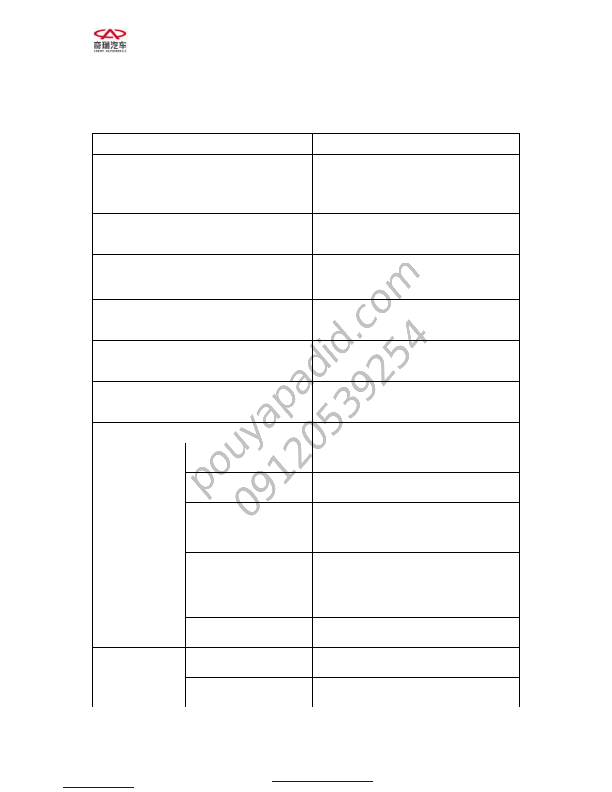
1. Remove the upper cover of engine timing
belt.
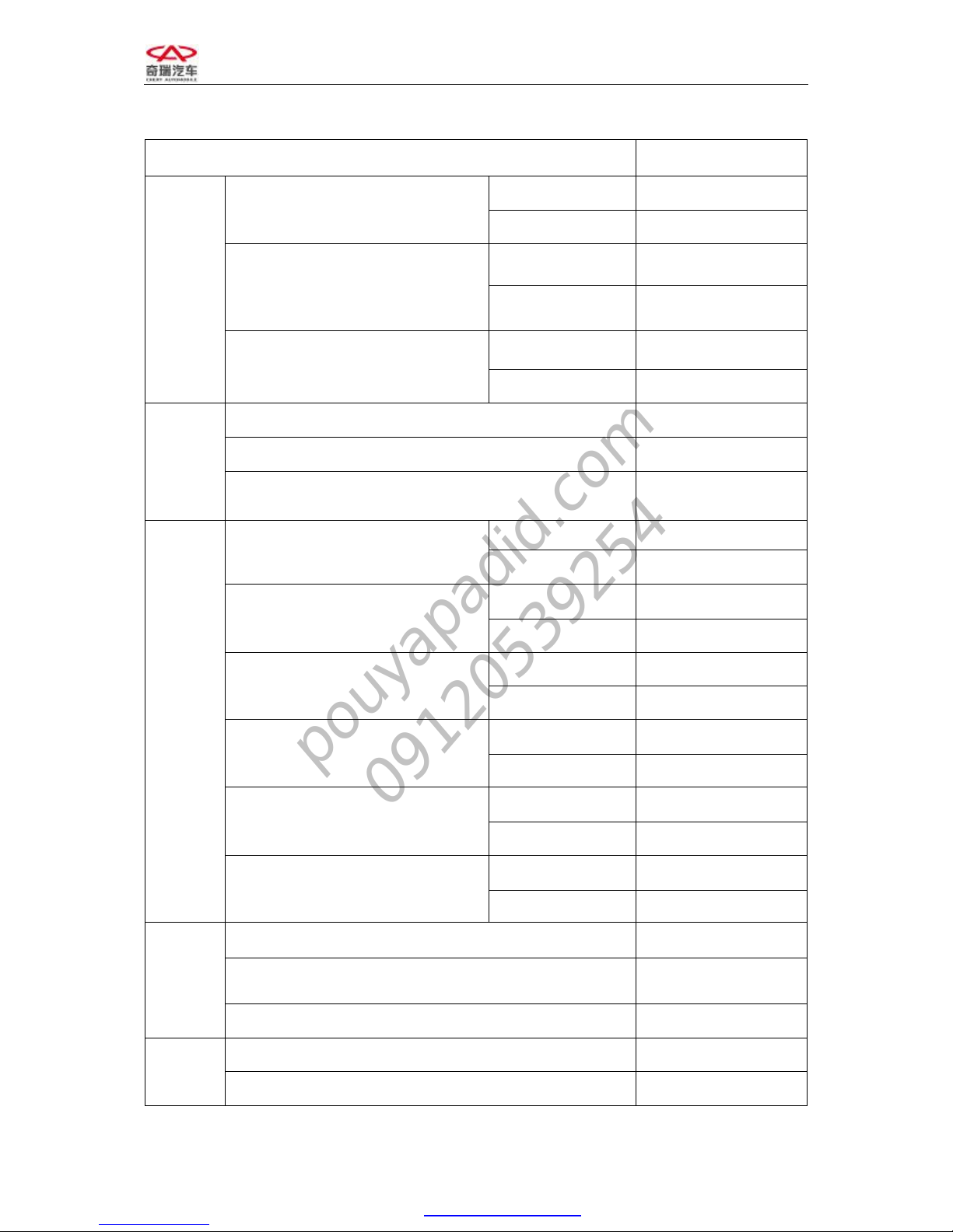
2. Remove the lower cover of engine timing
belt.
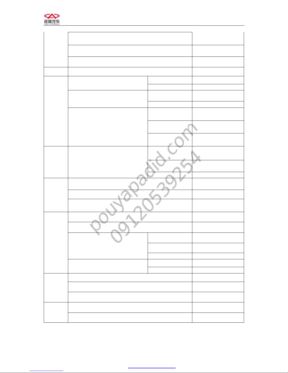
3. Loosen the central bolt of timing belt
tension pulley and remove the timing
belt.
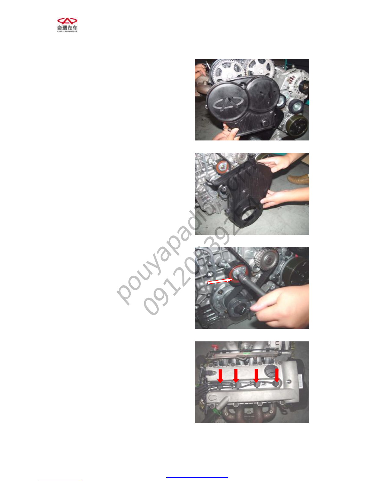
4. Draw out the high voltage ignition cable.
PDF created with pdfFactory Pro trial version www.pdffactory.com
pouyapadid.com
09120539254
Page 8
CHERY A21 SERVICE MANUAL MECHANISM OF 2.0NALC ENGINE
8
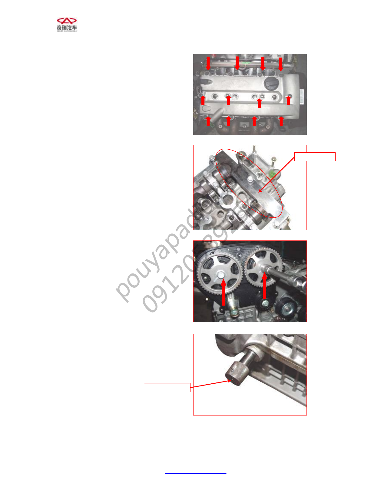
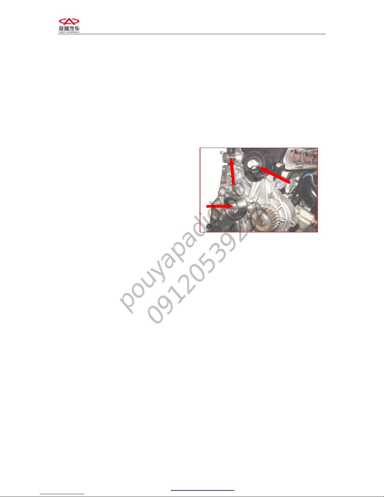
5. Loosen the bolt of valve cover and
remove the valve cover.
6. Rotate the camshaft in order to clip the
camshaft tool into the slot at the end of
camshaft.
7. Loosen the bolts of air intake and exhaust
camshaft tension pulleys with torque
wrench.
Note: It is not to remove but loosen.
8. Revolving the crankshaft, you may rotate
in the crankshaft tool so as to it cannot
move in both direction.
Note: Do it with patience and carefulness lest
the crankshaft should be broken.
Camshaft Tool
Crankshaft Tool
PDF created with pdfFactory Pro trial version www.pdffactory.com
pouyapadid.com
09120539254
Page 9

CHERY A21 SERVICE MANUAL MECHANISM OF 2.0NALC ENGINE
9
9. Mount the timing belt and rotate tension
pulley with Allen wrench in order to
tension the belt and make the finger of
tensioner point to the middle of U slot
opening. Fasten the bolt of tension pulley,
the fastening bolts of air intake and
exhaust camshaft tension pulleys and
camshaft.
Torque: 120±5Nm.
10. Remove the special timing tool, and
mount the valve cover, the high voltage
ignition cable and the timing belt cover.
CHAPTER 2 ENGINE BODY
SECTION 1 WHEEL TRAIN
I. STRUCTURAL DIAGRAM
Part Name Torque value Nm Re-screw angle
1
Bolt– Lower Part Of Timing
Front Cover
8+3
2
Bolt– Upper Part Of Timing Front
Cover
8+3
3
Bolt– Upper Part Of Timing Front
Cover
8+3
4
Lower Part Of Timing Front
Cover
5
Upper Part Of Timing Front
Cover
6
Washer- Lower Part Of Timing
Front Cover
7 Bolt- Crankshaft Timing Gear 130+10 65+5
8 Washer- Crankshaft Timing Gear
9 Crankshaft Timing Gear
10 Timing Belt
11 Water Pump
12 Bolt- Timing Gear Rear Cover 5+1.5
13 Timing Gear Rear Cover
14 Camshaft Timing Gear
15 Bolt- Camshaft Timing Gear 120+5
16 Bolt- Timing Tensioner 27+2.7
17 Timing Tensioner
18 Bolt- Timing Idler wheel 40+5
19 Timing Idler wheel
20 Contact Idler wheel
21 Bolt- Contact Idler wheel 40+5
PDF created with pdfFactory Pro trial version www.pdffactory.com
pouyapadid.com
09120539254
Page 10
CHERY A21 SERVICE MANUAL MECHANISM OF 2.0NALC ENGINE
10
II. MAINTENANCE
1. Replace upper and lower covers of timing
belt
1.1 Needed tools and auxiliary materials
Allen wrench, 10#, 13# sleeve, ratchet wheel
and ratchet rod.
1.2 Removal
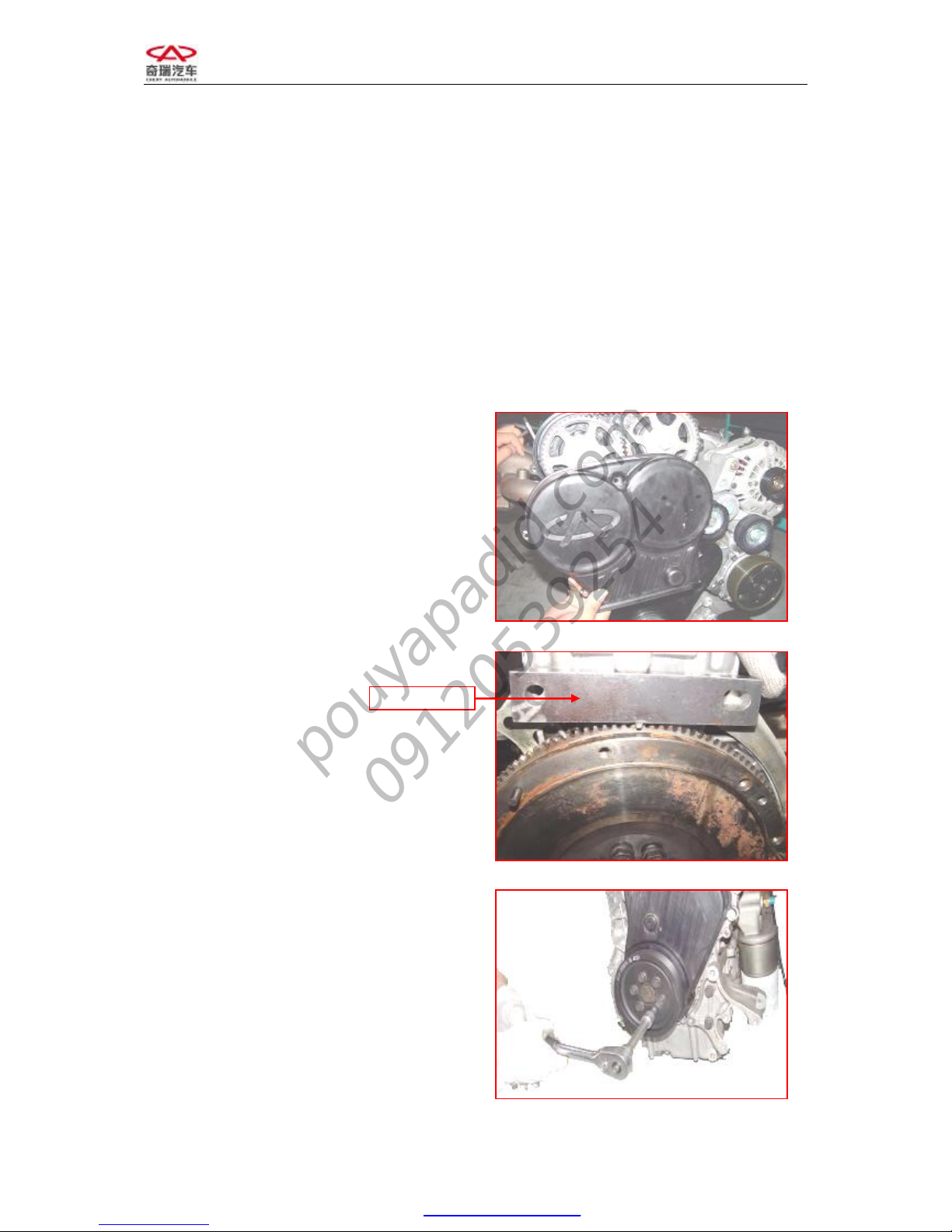
1) Loosen the five bolts on the upper cover
with Allen wrench.
2) Remove the upper cover of timing belt.
3) Clip the flywheel with flywheel tool.
4) Remove the crankshaft pulley with 13#
sleeve.
Flywheel Tool
PDF created with pdfFactory Pro trial version www.pdffactory.com
pouyapadid.com
09120539254
Page 11
CHERY A21 SERVICE MANUAL MECHANISM OF 2.0NALC ENGINE
11
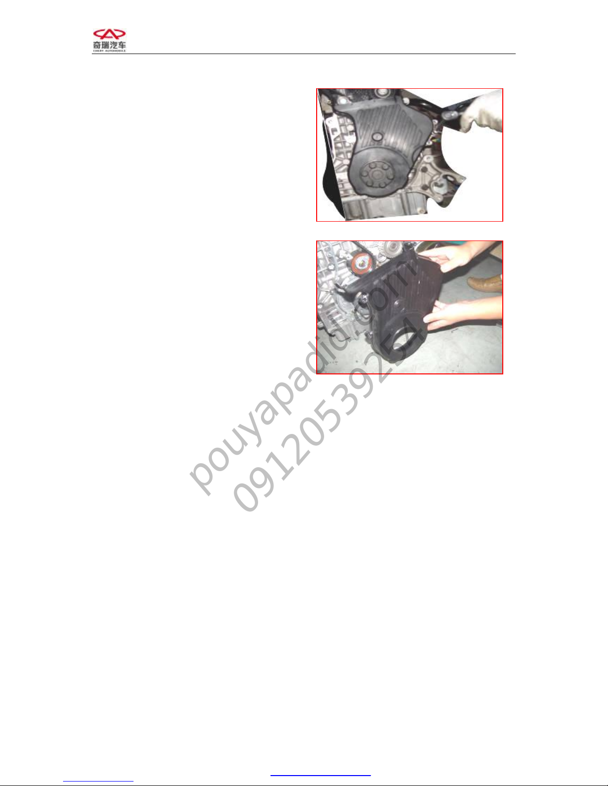
5) Remove the 5 bolts on the lower cover
of timing belt with 10# sleeve, ratchet
wheel and ratchet rod.
6) Remove the lower cover.
1.3 Inspection
Observe the timing cover and the timing belt.
Replace the timing belt cover or adjust the
position of timing belt if any trail from crack
or friction is found.
1.4 Installation
The installing steps are reverse to those for
removal.
Note: Install the lower cover first and then
install the upper one.
2. Replace timing belt
2.1 Needed tools and auxiliary materials
Allen wrench, 10#, 13# sleeve, ratchet wheel
and ratchet rod.
2.2 Removal
1) Remove the upper and lower covers of
timing belt (see “replace covers of
PDF created with pdfFactory Pro trial version www.pdffactory.com
pouyapadid.com
09120539254
Page 12
CHERY A21 SERVICE MANUAL MECHANISM OF 2.0NALC ENGINE
12
timing belt” for details).
2) Loosen the central bolt of tension pulley
and remove the timing belt.
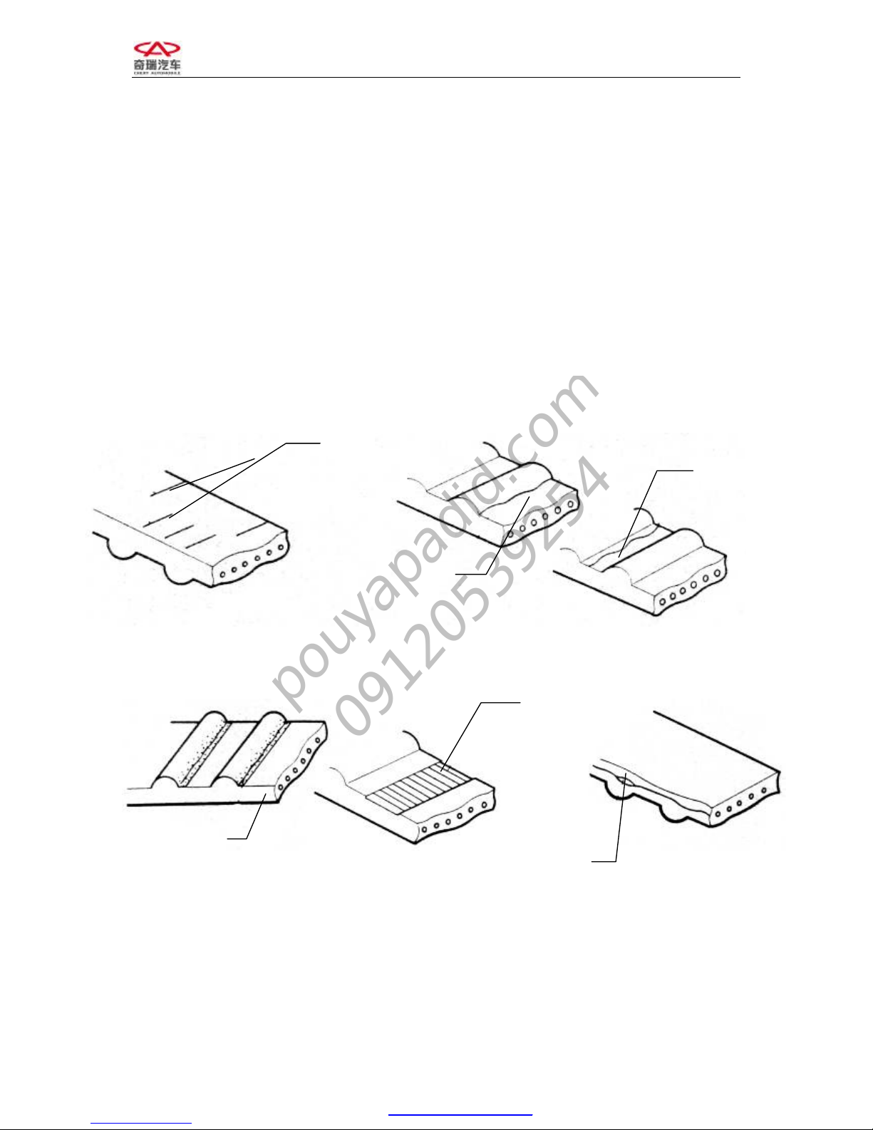
2.3 Inspection
Check the timing belt carefully; replace the
parts if any following situation occurs.
(1) Chap of back-side rubber
(2) Chap of dedendum, chap of separated
cord fabric.
(3) Wearing, gear missing and incomplete
gear of cord fabric.
(4) Abnormal wearing of belt flank.
Replace the belt as any following situation occurs, even though abrasion cannot be found
directly.
1) The water pump leaks water out, and requires continuing infusion.
2) If the belt is spotted with much oil stains, and the rubber may be damaged due to
expansion, you should replace the belt.
Chap
Chap
Wearing
Abnormal Wearing
Gear Missing
Belt Core Desquamation
PDF created with pdfFactory Pro trial version www.pdffactory.com
pouyapadid.com
09120539254
Page 13
CHERY A21 SERVICE MANUAL MECHANISM OF 2.0NALC ENGINE
13
2.4 Installation
The installing steps are reverse to those for
removal.
Note: Do engine timing.
3. Replace idler wheel, tensioner and
contact belt pulley
3.1 Needed tools and auxiliary materials
Allen wrench, 10#, 13# and 15# sleeve,
ratchet wheel and ratchet rod.
3.2 Removal
1) Remove the timing belt (see “replace
timing belt” for details).
2) Remove idler wheel, tension pulley and
contact belt pulley.
3.3 Inspection
1) Check from appearance
Check idler wheel, tension pulley and contact
belt pulley carefully for any damages, such as
sunken trace and sliding damage etc.
2) Check performance
Revolve tension pulley, idler wheel and
contact belt pulley respectively to insure that
they can run freely without stagnancy.
Replace it with the spare part if any above
problem is found.
3.4 Installation
1) The installing steps of tension pulley,
idler wheel and contact belt pulley are
reverse to those for removal.
2) Mount the timing belt and collate engine
timing.
3) Mount other parts.
PDF created with pdfFactory Pro trial version www.pdffactory.com
pouyapadid.com
09120539254
Page 14
CHERY A21 SERVICE MANUAL MECHANISM OF 2.0NALC ENGINE
14
SECTION 2 CYLINDER HEAD
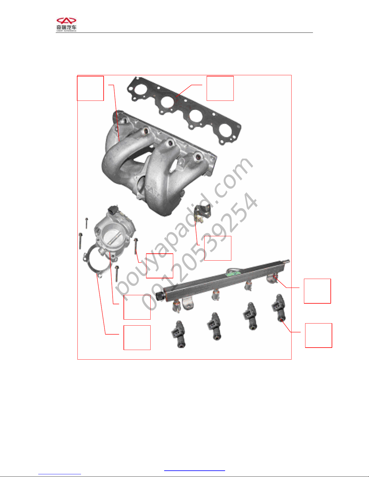
I. STRUCTURAL DIAGRAM
1. Gasket—Intake Manifold
2. Intake Manifold Assembly
3. Hexagonal Flange Bolt
4. Throttle Valve Body Assembly
5. Gasket—Throttle Valve Body Assembly
6. Oil injector Assembly
7. Fuel Distribution Pipe Assembly
8. Bracket
4
7
6
2 1
3
5
8
PDF created with pdfFactory Pro trial version www.pdffactory.com
pouyapadid.com
09120539254
Page 15

CHERY A21 SERVICE MANUAL MECHANISM OF 2.0NALC ENGINE
15
1. Intake Valve
2. Valve Oil Seal
3. Valve Spring Seat
4. Valve Spring
5. Valve Spring Retainer
6. Keeper
7. Exhaust Valve
8. Intake Camshaft Assembly
9. Bearing Cap Assembly
10. Control Valve-Camshaft Phaser Assembly
11. First Bearing Cap Assembly
12. Front Camshaft Oil Seal
13. Exhaust Camshaft Assembly
14. Rocker Arm Assembly
15. Hydraulic Tappet Assembly
16. Stud Bolt (9 Bars)
17. Cylinder Head Gasket
18. Temperature Sensor
19. Engine Hanger
20. Cylinder Head Bolt
21. Cylinder Head Assembly
11
15
14
13
8 9 10
17
7
18
1
5
4
3
2
6
12
16
19
20
21
PDF created with pdfFactory Pro trial version www.pdffactory.com
pouyapadid.com
09120539254
Page 16

CHERY A21 SERVICE MANUAL MECHANISM OF 2.0NALC ENGINE
16
II. MAINTENANCE
2.1 Replace intake manifold, delivery pipe
and oil injector
2.1.1 Needed tools and auxiliary materials
Ratchet wheel, ratchet rod, 10# sleeve and
crosshead screwdriver
2.1.2 Process of removal
1) Put the ignition key at the OFF position.
2) Loosen the plug of oil injector.
3) Remove the connecting bolt between
engine oil dipstick and intake manifold.
4) Remove the clamp between intake hose
and throttle valve body.
5) Remove the connecting bolt of throttle
valve body, and take out throttle valve
body.
Note: Because this throttle valve body is
electronic, do not force the middle vanes
turning manually or with other objects.
6) Loosen the joint of oil intake pipe.
7) Remove the fastening nut of intake
manifold and take out the intake
manifold.
PDF created with pdfFactory Pro trial version www.pdffactory.com
pouyapadid.com
09120539254
Page 17

CHERY A21 SERVICE MANUAL MECHANISM OF 2.0NALC ENGINE
17
2.1.3 Installation steps
The installing steps are reverse to those for
removal.
2.2 Replace camshaft, bearing bushings,
valve and valve oil seal.
2.2.1 Needed tools and auxiliary materials
Special tools for valve oil seal, engine
transmission oil, a set of sleeve tools, an
adjustable spanner, special tools for timing
and a set of Allen wrenches
2.2.2 Removal
1) Remove the dynamo belt (see “removal
of dynamo belt” for details).
2) Remove the timing belt (see
“replacement of engine timing belt and
timing calibration” for details).
3) Remove the cover of engine valve
chamber.
4) Clamp the timing special tool into
camshaft slot and fasten the bolt.
Camshaft Tool
PDF created with pdfFactory Pro trial version www.pdffactory.com
pouyapadid.com
09120539254
Page 18

CHERY A21 SERVICE MANUAL MECHANISM OF 2.0NALC ENGINE
18
5) Dismantle the belt pulley of air intake
and exhaust camshafts with torque
wrench.
6) Remove the back cover of timing belt.
7) Dismantle the bearing caps of air intake
and exhaust camshaft respectively and
put them down in the sequence.
Note: The second, third, fourth and fifth
camshaft bearing caps are marked with I1, I2,
I3, I4 (E1, E2, E3, E4), which stands for the
corresponding bearing cap of 1, 2, 3, 4
cylinder respectively. (“I” refers to intake
camshaft, “E” refers to exhaust camshaft).
Torque:
PDF created with pdfFactory Pro trial version www.pdffactory.com
pouyapadid.com
09120539254
Page 19

CHERY A21 SERVICE MANUAL MECHANISM OF 2.0NALC ENGINE
19
See the following picture for removal sequence of intake and exhaust camshaft-bearing caps:
8) Take out the camshaft and the hydraulic tappet.
9) Remove the valve spring with special tools. (Picture is unavailable)
10) Remove the used valve oil seal with special tools. (Picture is unavailable)
2.2.3 Inspection
1) Check the valve spring.
Measure the free length, the verticality and
the length under special pressure with caliper.
Standard
Value(mm)
Free length 47.7
Length of
620N
32
Replace with the new valve spring if the
measured value exceeds the limit value.
PDF created with pdfFactory Pro trial version www.pdffactory.com
pouyapadid.com
09120539254
Page 20

CHERY A21 SERVICE MANUAL MECHANISM OF 2.0NALC ENGINE
20
2) Check camshaft
Measure the camshaft diameter with
micrometer caliper.
Standard Value
(mm)
Limit Value
(mm)
Diameter ¢24
-0.053
-0.040
Replace with the new camshaft if the
measured value exceeds the limit value.
3) Examine camshaft
Measure the high of cam with micrometer
caliper.
Standard Value
(mm)
limit value
(mm)
Intake
Cam
37.15
Exhaust
Cam
37.05
Replace with the new camshaft if the
measured value exceeds the limit value.
4) Examine diameter of valve stem
a: Measure the diameter of valve stem with
micrometer caliper.
See the picture for measuring points: they are
26, 52, and 78 mm from measure positions to
bottom of valve.
Valve
Guide
External Diameter
Of Valve Stem
Internal Diameter
Of Valve Guide
Measuring Point
PDF created with pdfFactory Pro trial version www.pdffactory.com
pouyapadid.com
09120539254
Page 21

CHERY A21 SERVICE MANUAL MECHANISM OF 2.0NALC ENGINE
21
b: Use internal micrometer guage to
measure the internal diameter of valve
guide and the measuring point is a
quartering point of guide.
c: Calculate the difference of measured
value and the clearance.
Replace the valve or the guide if the value
exceeds the limit value.
d: Examine the contact bandwidth of
valve.
e: Check the valve seat insert.
Standard
Value
IN ¢5.98±0.008
Outer Diameter
of Valve stem
(mm)
EX ¢5.96±0.008
IN
¢5.4±0.1 Inner Diameter
of Valve guide
(mm)
EX ¢5.4±0.1
IN
0.02 Clearance
(mm)
EX
0.04
IN
0.3±0.15
Thickness of
Valve Top
(mm)
EX
0.3±0.15
IN
1.158 Seal Bandwidth
(mm)
EX
1.306
Measuring Point
Contact Position (Should be
the Center of Slope)
Edge
Thickness
PDF created with pdfFactory Pro trial version www.pdffactory.com
pouyapadid.com
09120539254
Page 22

CHERY A21 SERVICE MANUAL MECHANISM OF 2.0NALC ENGINE
22
f: Examine the protruding capacity of
valve stem.
And Examine the protruding high of valve
stem with vernier caliper.(See picture)
Standard Value( mm)
Protruding Capacity
Of Intake Valve
stem
47.5
Protruding Capacity
Of Exhaust Valve
stem
47.5
5) Examine the axial clearance of camshaft.
Replace the camshaft if the value of axial
clearance exceeds the normal value.
Standard Value
Intake camshaft 0.015—0.02
Exhaust camshaft 0.015—0.02
6) Examine the planeness of cylinder
a: Clear the lower surface of cylinder head.
b: With the help of ruler and feeler gauge,
check whether the lower surface of
cylinder head is warped.(Measure it in
the sequence of A, C, D, E, F, G in the
picture)
Standard
Value
Cylinder head planeness
0.04
Top of Valve
Stem
Protruding High of Valve S
tem
Seat of Valve
Spring
PDF created with pdfFactory Pro trial version www.pdffactory.com
pouyapadid.com
09120539254
Page 23

CHERY A21 SERVICE MANUAL MECHANISM OF 2.0NALC ENGINE
23
C: Revise it if the planeness exceeds, and
replace when it exceeds the limit value.
The permitted maximum abrading thickness
between cylinder block and cylinder head is:
2.2.3 Installation
The installing steps are reverse to those for
removal.
Note:
1) Dismantle valve springs into groups.
The 1st and 4th cylinders are in one
group and the 2nd and 3rd ones are in
the other group. Then put the piston to
the upper point of 1st and 4th cylinders
in order to dismantle the valve spring of
1st and 4th cylinders, replace their valve
oil seal and mount the spring
immediately. And put the piston to the
upper point of 2nd and 3rd cylinders in
order to replace the other valve oil seal.
Those steps prevent from that the valve
falls into cylinder and the unanticipated
trouble occurs.
2) Wipe the engine transmission oil on the
opening of oil seal when mounting the
valve oil seal.
3) Fasten the cylinder bolt as the following
process.
A: Smear some oil on the top and root of
bolt.
B: Fasten to 40±5NM in sequence.
C: Fasten 90±5 degree clockwise.
D: Fasten 90±5 degree clockwise.
2.3 Replace thermostat
2.3.1 Structural diagram
8 4 1 5 9
7 3 2 6 10
PDF created with pdfFactory Pro trial version www.pdffactory.com
pouyapadid.com
09120539254
Page 24

CHERY A21 SERVICE MANUAL MECHANISM OF 2.0NALC ENGINE
24
2.3.2 Needed tools and auxiliary materials
Hatch clamp,10# sleeve, ratchet wheel and wrench
2.3.3 Removal
1) Loosen the clamp of thermostat water exhaust pipe with hatch clamp to release the
coolant.
Note: Do it after the temperature decreased to prevent scald.
2) Remove the 4 bolts of thermostat cover with 10# sleeve wrench.
3) Take out the thermostat.
2.3.4 Inspection
Put the thermostat in the boiling water and use it with thermometer. Then observe the
temperatures when the thermostat is turning on and fully opened.
Temperature value
Regular unlocking temperature 87℃
fully opened temperature 104℃
Replace the new thermostat if the measured value is abnormal.
2.3.5 Installation
The installing steps are reverse to those for removal.
Note: Fill in the engine coolant with fixed quantity after installation.
1
2
3
4
5
6
1. Pad—Thermostat Seat
2. Thermostat Seat
3. Hexagonal Flange Bolt
4. Thermostat Assembly
5. Hexagonal Flange Bolt
6. Cover—Thermostat Seat
PDF created with pdfFactory Pro trial version www.pdffactory.com
pouyapadid.com
09120539254
Page 25

CHERY A21 SERVICE MANUAL MECHANISM OF 2.0NALC ENGINE
25
SECTION III SHORT ENGINE
I. STRUCTURE DIAGRAM
1. Piston
2. Connecting Rod Upper Bearing
3. Timing Hole Plug
4. Connecting Rod Lower Bearing
5. Pad
6. Bolt
7. Oil Filter
8. Oil Cooler
9. Oil Filter Seat
10. Connecting Rod Bolt
11. Connecting Rod Bearing Cap
12. Oil Pump
13. Bolt
14. Gasket
15. Crankshaft Timing belt pulley
16. Gasket
17. Bolt
18. Crankshaft Pulley
19. Bolt
20. Bolt
21. Coolant pump
22. Coolant Pump Gasket
PDF created with pdfFactory Pro trial version www.pdffactory.com
pouyapadid.com
09120539254
Page 26

CHERY A21 SERVICE MANUAL MECHANISM OF 2.0NALC ENGINE
26
23. Crankshaft Main Bearing Bolt
24. Frame Bolt
25. Frame
26. O-Type Ring
27. Crankshaft
28. Cylinder Block
PDF created with pdfFactory Pro trial version www.pdffactory.com
pouyapadid.com
09120539254
Page 27

CHERY A21 SERVICE MANUAL MECHANISM OF 2.0NALC ENGINE
27
II. MAINTENANCE
1. Replace oil pan
1.1 Needed tools and auxiliary materials
10# open end wrench, 10#, 15# and 17#
sleeve, ratchet wheel and ratchet rod, Le Tai
5901 Glue, engine oil
1.2 Process of Replacement
1.2.1 Process of removal
1) Loosen the oil discharge bolt of oil pan
to discharge the engine oil.
Note: Engine oil should be stored in special
container. And Pay attention to environment
protection.
2) Remove the fastening bolt of oil pan
with 10# open end wrench and 10#
sleeve.(18 bars of M7×25, 3 bars of
M7×40,4 bars of M7×95)
3) Remove the connecting bolt (2 bars,
black) between oil pan and transmission
housing with 17# sleeve wrench.
PDF created with pdfFactory Pro trial version www.pdffactory.com
pouyapadid.com
09120539254
Page 28

CHERY A21 SERVICE MANUAL MECHANISM OF 2.0NALC ENGINE
28
4) Remove the connecting bolt between the
oil return pipe of PVC valve and the oil
pan with 15# sleeve wrench.
5) Tap the edge of oil pan with rubber
pestle, and then remove the oil pan.
Note: Pay attention to safety because the oil
pan might fall down when being tapped.
6) Clean the engine frame with
right-angled tool to get rid of old Le Tai
glue.
Note: Do not lacerate the frame surface.
1.2.2 Installation
1) Spread Le Tai 5910 glue on the
connection surfaces of frame and oil
pan, close the oil pan and fasten the
fastening bolt of oil pan.
Note: Spread glue to the inner of hole for
installing bolt on the oil pan!
2) Screw the bolt. Screw to combine
enough at first then to get specified
Torque.
See the diagram for screwing sequence.
Torque: 15±3NM
3) Infuse engine oil to specified capacity.
PDF created with pdfFactory Pro trial version www.pdffactory.com
pouyapadid.com
09120539254
Page 29

CHERY A21 SERVICE MANUAL MECHANISM OF 2.0NALC ENGINE
29
2 Replace the engine oil strainer
2.1 Needed tools and auxiliary materials
10# open end wrench, 10#, 15#, 17# sleeve,
ratchet wheel and ratchet rod, Le Tai 5901
Glue, engine oil
2.2 Process of replacement
2.2.1 Process of removal
1) Remove the oil pan.(See “replace oil
pan” for details)
2) Remove the connecting bolt between
engine oil strainer and frame with 10#
sleeve wrench.(total 8 bars)
3) Draw out the engine oil strainer
carefully.
2.2.2 Installation
1) Spin the nozzle of engine oil strainer
into the frame carefully.
2) Mount the 8 bolts for the strainer and
fasten them.
Note: the bolts should be mounted with Le
Tai 243 glue.
Torque: 8±3Nm
3) Install oil pan (See “installation of oil
pan” for details).
PDF created with pdfFactory Pro trial version www.pdffactory.com
pouyapadid.com
09120539254
Page 30

CHERY A21 SERVICE MANUAL MECHANISM OF 2.0NALC ENGINE
30
3 Replace the piston, piston ring, piston
pin and connecting rod bearing
3.1 Needed tools and auxiliary materials
10# open end wrench, 10#, 15#, 17# sleeve,
ratchet wheel and ratchet rod, Le Tai 5901
Glue, engine oil, torque wrench Special tools
for installing piston, feeler gauge, clearance
gauge, micrometer caliper
3.2 Process of replacement
3.2.1 Process of removal
1) Dismantle the timing belt (see
“dismantle the timing belt” in the
section of “replacement of engine
timing belt” for details).
2) Remove the oil pan(see REPLACE OIL
PAN for details.
3) Remove the cylinder head. (see
“removal of cylinder head” for details).
4) Dismantle the engine oil strainer (see
the “replacement of engine oil strainer”
for details).
5) Loosen the big bolt on connecting rod.
6) Remove the connecting rod bearing
lower cover.
Connecting Rod
Bearing Lower Cap
PDF created with pdfFactory Pro trial version www.pdffactory.com
pouyapadid.com
09120539254
Page 31

CHERY A21 SERVICE MANUAL MECHANISM OF 2.0NALC ENGINE
31
7) Uplift the connecting rod and the piston
with a wooden stem and then remove
the connecting rod and piston assembly.
8) Remove the piston ring.
9) Remove the retainer ring of piston pin
and draw out the piston pin.
Note: With large tension, the retainer ring
may hurt people in the process of removal.
3.2.2 Inspection
I. Check piston
1) Examine the diameter of piston.
Measure the diameter along the vertical
direction to piston pin and at the place 11mm
under piston skirt with micrometer caliper.
Cylinder No.
Standard Size
1 83.46±0.009
2 83.46±0.009
3 83.46±0.009
4 83.46±0.009
Replace with the new one if the part cannot
be worn and torn any longer.
Retainer Ring
PDF created with pdfFactory Pro trial version www.pdffactory.com
pouyapadid.com
09120539254
Page 32

CHERY A21 SERVICE MANUAL MECHANISM OF 2.0NALC ENGINE
32
2) Examine the clearance between piston
ring and ring groove.
a. Clean up the accumulated carbon in the
ring groove with piston ring.
b. Examine the clearance between piston
ring and ring groove with feeler gauge.
Reference Value(mm)
1st Ring
0.04--0.08
2nd Ring
0.01--0.025
Replace with the new one if the examined
clearance cannot be worn and torn any
longer.
3) Inspect the end clearance of piston ring.
a. Put the piston ring at the position 45mm
below the top surface of cylinder
aperture and push the piston ring into
cylinder with piston.
b. Measure the opening with feeler gauge.
Replace with the new piston if the examined
clearance exceeds the limit.
PDF created with pdfFactory Pro trial version www.pdffactory.com
pouyapadid.com
09120539254
Page 33

CHERY A21 SERVICE MANUAL MECHANISM OF 2.0NALC ENGINE
33
4) Inspect the diameter of piston pin and
piston pin hole.
a. As the following picture, measure the
piston pin position around with
micrometer caliper. And take the
maximum value as the diameter of
piston pin.
b. Measure the diameter of piston pin hole
around with micrometer guage for
inside diameter, as the following picture,
and take the minimum value as the
diameter of pin hole.
Replace with the new piston and pin if the
examined clearance exceeds the limit.
Standard
Size
Diameter of piston pin
21
0
005.0−
Diameter of piston pin
hole
21
008.0
002.0
PDF created with pdfFactory Pro trial version www.pdffactory.com
pouyapadid.com
09120539254
Page 34

CHERY A21 SERVICE MANUAL MECHANISM OF 2.0NALC ENGINE
34
5) Inspect the connecting rod journal and
connecting rod bearing
a. Examine the diameter of connecting rod
journal.
Measure the axle diameter of connecting rod
with micrometer caliper.
Rotate the crankshaft 90° and measure it
again.
Work out the Roundness and cylindricity
through twice measuring.
① Roundness=Max. diameter — Min.
diameter /2 as the picture, take the
vertical diameters on the same plane,
subtract the half of Minimum from the
Maximum to get roundness.
② cylindricity= Maximum bore -
Minimum bore/2 As the picture,
measure the bores of 3 planes along
both A direction and B direction
respectively. Get the maximum and the
minimum from 6 values, and then
subtract the half of Minimum from the
Maximum to get cylindricity;
b. Inspect the radial clearance of
connecting rod bearing
Inspect the radial clearance of connecting rod
bearing with clearance gauge. Clean up the
connecting rod journal and connecting rod
bearing. And put clearance gauge on the
journal, fasten bearing bushing and fasten the
bolt according to set torque.
Note: Do not rotate the crankshaft during the
process.
Standard Value
Diameter
9.47
0
016.0−
Roundness
——
Cylindricity
——
PDF created with pdfFactory Pro trial version www.pdffactory.com
pouyapadid.com
09120539254
Page 35

CHERY A21 SERVICE MANUAL MECHANISM OF 2.0NALC ENGINE
35
Loosen the connecting rod bolt, remove the
cap, and measure the maximum width of
pressed clearance gauge with the ruler on its
package to get the clearance value.
Replace with the new connecting rod bearing
if the examined clearance exceeds the limit.
Note: Use the same brand consistent with
assorting sign when you replace the bearing
bushing.
Standard
Value
Abrasion
Limit
Clearance 0.016—0.051
Selection of connecting rod bearing:
You may select the connecting rod bearing by
observing the sign on the first balance weight
at the front end of crankshaft.(see picture,
unavailable)
6) Inspect the planeness of cylinder block
surface.
a: Clean the upper surface of cylinder
block.
b: Check with ruler and feeler gauge
whether the surface of cylinder block is
warped. (Measure it in the sequence of
A, C, D, E, F, G in the picture)
C: Revise it if the warping amount is
excessive.
Replace with the new cylinder if it exceeds
the limit. The maximum for the sum of
permitted abrading thickness of cylinder
block and cylinder head is:
Standard Value
limit
value
warping
amount
0.04
Clearance Gauge of Plastic
PDF created with pdfFactory Pro trial version www.pdffactory.com
pouyapadid.com
09120539254
Page 36

CHERY A21 SERVICE MANUAL MECHANISM OF 2.0NALC ENGINE
36
7) Inspect cylinder
a: Inspect if the cylinder wall is scratched
or scored. If there are cylinder scoring
and scratching you need to hone cylinder
wall, replace cylinder liner or replace
cylinder block.
b: Examine the inner diameter and
cylindricity of cylinder with cylinder
gauge.
Standard value
Inner diameter 83.5
cylindricity 0.008
cylindricity= Maximum bore - Minimum
bore/2
As the picture, measure the bores of 3 planes
along both A direction and B direction
respectively. Get the maximum and the
minimum from 6 values, and then subtract the
half of Minimum from the Maximum to get
cylindricity;
3.2.3 Installation
1) Spread oil on the piston pin and in the
piston pin hole, connect the piston and
connecting rod with piston pin, and
mount the piston pin circlip.
2) Mount the piston ring. Mount the rings
on the piston in the sequence of oil ring
expander, upper and lower segments, 2nd
air ring and 1st air ring; Pay attention to
the direction of piston ring, the side with
“TOP” should be upward. The two
segments and expander are staggered.
The angle of expander connector points
to the top of piston, and the 1st ring and
2nd ring form 120° with the upper
expander.
12 mm
Center
Bottom
The Openings Of Rings Form
PDF created with pdfFactory Pro trial version www.pdffactory.com
pouyapadid.com
09120539254
Page 37

CHERY A21 SERVICE MANUAL MECHANISM OF 2.0NALC ENGINE
37
3) Mount the upper bearing of connecting
rod and the connecting rod together.
Note: the gap on bushing should be orderly
with that of connecting rod.
4) Spread the engine transmission oil in the
engine cylinder, clasp the piston ring
with special tool, tap the piston head
with wooden handle and encase the
piston connecting rod assembly.
Note: the end of connecting rod with a point
should face the cylinder and consists with the
arrowhead on the top side of piston.
PDF created with pdfFactory Pro trial version www.pdffactory.com
pouyapadid.com
09120539254
Page 38

CHERY A21 SERVICE MANUAL MECHANISM OF 2.0NALC ENGINE
38
5) Mount the lower bearing of connecting
rod and the connecting rod cap together.
Then spread engine transmission oil.
Note: the gap on bushing should be orderly
with that of connecting rod.
6) Close the connecting rod cap and screw
down the bolt.
Torque: 25±3N•m, then screw 90°±5°
7) Examine the axial clearance of
connecting rod.
Examine the axial clearance with micrometer
guage or feeler gauge.
Standard Value(mm)
Clearance 0.15—0.50
8) Mount the engine oil strainer.
9) Mount the oil pan.
10) Mount the cylinder head.
11) Mount the timing belt during timing
adjusting.
4.Replace front oil seal of crankshaft
4.1 Needed tools and auxiliary materials
Ratchet wheel and ratchet rod, 13#, 15#, 17#,
22# sleeve, 13# open end wrench, allen
wrench, engine transmission oil and guide
sleeve of crankshaft oil seal
4.2 Process of Replacement
4.2.1 Process of Removal
1) Dismantle the timing belt (See
“replacing the timing belt” for details).
PDF created with pdfFactory Pro trial version www.pdffactory.com
pouyapadid.com
09120539254
Page 39

CHERY A21 SERVICE MANUAL MECHANISM OF 2.0NALC ENGINE
39
2) Engage the gear to 5th, then press the
brake with toes, Dismantle the
connecting bolt of timing belt pulley and
crankshaft with torque wrench. Remove
the timing belt.
Torque:130±10,then screw 65°±5°
3) Pry out the old oil seal with right-angled
screwdriver carefully.
Note: Be careful in dismantling the oil seal
not to damage the oil seal seat ring.
4.2.2 Installation
1) Clean the oil seal seat ring and spread
transmission oil on the seat ring
2) Spread transmission oil at the seal lip.
3) Enclose the guide sleeve of crankshaft
oil seal, special tool, with that oil seal.
4) Press the oil seal into oil seal seat ring
and knock it to right position with
hammer.
5. Replacement of oil pump
5.1 Needed tools and auxiliary materials
A set of big sleeves, a set of small sleeves
and a set of open end wrench
Guide Sleeve of Crankshaft Oil Seal
PDF created with pdfFactory Pro trial version www.pdffactory.com
pouyapadid.com
09120539254
Page 40

CHERY A21 SERVICE MANUAL MECHANISM OF 2.0NALC ENGINE
40
5.2 Process of Replacement
5.2.1 Process of Removal
1) Dismantle the timing belt (See “removal
of timing belt” for details).
2) Engage the gear to 5th, then press the
brake with toes, and remove the timing
belt pulley.
3) Dismantle the fastening bolt of oil pump
with 10# sleeve and take out the oil
pump. Torque:8+3NM
4) Pry out the oil seal.
5) Clean the seat ring of oil pump.
5.2.2 Installation
1) Spread oil on the gasket of oil pump.
2) Mount the oil pump in its seat ring.
Note: The bulge of oil pump should be put
downwards because the wrong position can
not make the bolt be screwed in.
3) Mount the oil seal.
4) Mount the other parts.
6. Replacement of crankshaft rear oil seal
6.1 Needed tools and auxiliary materials
A set of big sleeves, a right-angled
screwdriver, a small hoist and engine oil
6.2 Process of Removal
1) Suspend the engine assembly from
vehicle (See “suspending of engine
assembly” for details).
2) Remove the clutch pressure plate.
3) For removing the flywheel, lock the flywheel
with special tool and then screw off the
fastening bolt with sleeve wrench.
4) Pry the old oil seal with the right-angled
screwdriver.
Note: Do not damage the oil seal seat ring.
Fastening
Flywheel Tool
PDF created with pdfFactory Pro trial version www.pdffactory.com
pouyapadid.com
09120539254
Page 41

CHERY A21 SERVICE MANUAL MECHANISM OF 2.0NALC ENGINE
41
6.2 Installation
1) Clean the oil seal seat ring. Clean the oil
seal seat ring with clean oiled gauze.
2) Spread the oil at the lip of crankshaft
front oil seal.
Enclose the guide sleeve of crankshaft oil
seal, special tool, with that oil seal. Then
press it into oil seal seat ring.
3) Mount the flywheel and the clutch
pressure plate, and then mount the
engine on the vehicle.
Torque:25±5N.M, then screw 30°±5°.
7. Replace crankshaft and thrust washer
7.1 Needed tools and auxiliary materials
A set of open end wrenches, a set of sleeve
tools, a small hoist, Le Tai glue, Engine oil,
feeler gauge, feeler gauge, micrometer gauge.
7.2 Process of Removal
1) Suspend the engine assembly from
vehicle (See “suspending of engine
assembly” for details).
2) Drain out the engine oil.
3) Remove the timing belt (see “replace
timing belt” for details).
Guide Sleeve of Crankshaft Oil Seal
PDF created with pdfFactory Pro trial version www.pdffactory.com
pouyapadid.com
09120539254
Page 42

CHERY A21 SERVICE MANUAL MECHANISM OF 2.0NALC ENGINE
42
4) Dismantle the accessories, such as
dynamo, A/C compressor, power
steering pump and bracket.(See the
“replacement of engine accessory” for
details)
5) Dismantle the engine cylinder head
assembly. ( See the “replacement of
cylinder head” for details)
6) Dismantle the engine clutch pressure
plate, the flywheel and the timing belt
pulley.
7) Remove the oil pan and engine oil
strainer.(See the “replacement of oil pan
and strainer” for details.)
8) Remove the piston connecting rod
assemblies for 4 cylinders and Put them
in order.
Note: You’d better stick the number on each
piston connecting rod assembly to prevent
from wrong mounting.
9) Dismantle engine oil pump assembly.
10) Dismantle the frame assembly under
cylinder block and remove the
crankshaft and thrust washer.
7.3 Inspection
1) radial clearance of crankshaft
a): Clean the journal and bearing bushing.
b): Install crankshaft
c): Make the length of plastic clearance
gauge equal to the width of bearing.
Then put it on the journal paralleling the
axis.
Clearance Gauge
PDF created with pdfFactory Pro trial version www.pdffactory.com
pouyapadid.com
09120539254
Page 43

CHERY A21 SERVICE MANUAL MECHANISM OF 2.0NALC ENGINE
43
d): Mount the main bearing cap carefully
and screw down the bolt with
specified torque.
e): Dismantle the main bearing cap
carefully.
f): Measure the width at the most bread
part of pressed plastic line with ruler on
plastic clearance gauge package, then
get clearance value.
Standard Value
Clearance
-0.0035-0.034
Replace the new bearing bushing if the
measured clearance value exceeds the limit
value.
Note: Replace the whole group when
replacing bearing bushing.
Selecting method of main bearing bushing:
By observing the sign on cylinder (see the
picture), we could see 5 As which correspond
to bearing bushings respectively.
There two kinds of signs on this vehicle, A
and B, corresponding to two kinds bushing,
red one and blue one (the color can be
recognized on the new bushing but it is
possible unrecognized the color on the old
one.) A corresponds to red bushing, and B
corresponds to blue bushing.
PDF created with pdfFactory Pro trial version www.pdffactory.com
pouyapadid.com
09120539254
Page 44

CHERY A21 SERVICE MANUAL MECHANISM OF 2.0NALC ENGINE
44
2) Inspect the crankshaft axial clearance
Mount the crankshaft and measure its radical
clearance with micrometer guage.
Standard Value
Clearance 0.076—0.265
Replace the new thrust washer if the
measured value exceeds the limit value.
Standard thickness of thrust washer:
7.4 Installation
1) Clean the engine and spread the engine
transmission oil on the crankshaft
journal.
2) Mount the crankshaft correctly and then
mount the thrust washer.
3) Mount the cylinder frame and screw
down the crankshaft fastening bolt.
See the picture for the screwing sequence
Screwing way and Torque:
A: Pre-fasten the bolt according to the
sequence in the picture.
B: Screw the bolt as the sequence on the
picture to 45±5 N.m.
C: Screw 180±5°
4) Mount and screw down the bolt of
frame periphery.
Torque: 23N.m
5) Mount the engine oil strainer, oil pan,
crankshaft front and rear oil seal and oil
pump.
6) Mount the engine accessories, suspend
the engine assembly from vehicle and
PDF created with pdfFactory Pro trial version www.pdffactory.com
pouyapadid.com
09120539254
Page 45

CHERY A21 SERVICE MANUAL MECHANISM OF 2.0NALC ENGINE
45
mount the water pipe and insert electric
connector.
8 Replace coolant pump
8.1 Needed tools and auxiliary materials
A box sleeve wrench, a set of open end
wrench, allen wrench, coolant
8.2 Removal
1) Remove the engine timing belt.(see
“engine timing calibration” for details.)
2) Loosen the engine water exhaust pipe,
and exhaust coolant.
3) Removal the coolant pump.
8.3 Installation
The installing steps are reverse to those for
removal.
Infuse enough coolant after installation.
Note: Do not splash the coolant on the timing
belt and skin.
PDF created with pdfFactory Pro trial version www.pdffactory.com
pouyapadid.com
09120539254
 Loading...