

Page 1

AIR CONDITIONER SYSTEM
AIR CONDITIONING SYSTEM OVERVIEW … … … … … … …… …… …… … U-2
REFILLING OF REFRIGERANT AND REFRIGERANT OIL … … … … … … … U-6
A/C SYSTEM COMPONENTS … … … … … … …… … … … … … …… ……… U-14
FAILURES AND SHOOTING ANALYSIS SHEET … … … … … … …… … … … U-20
PRECAUTIONS ON THE SECURITY OF A/C SYSTEM … … … … ……… …U-21
U-1
PDF created with pdfFactory Pro trial version www.pdffactory.com
Page 2
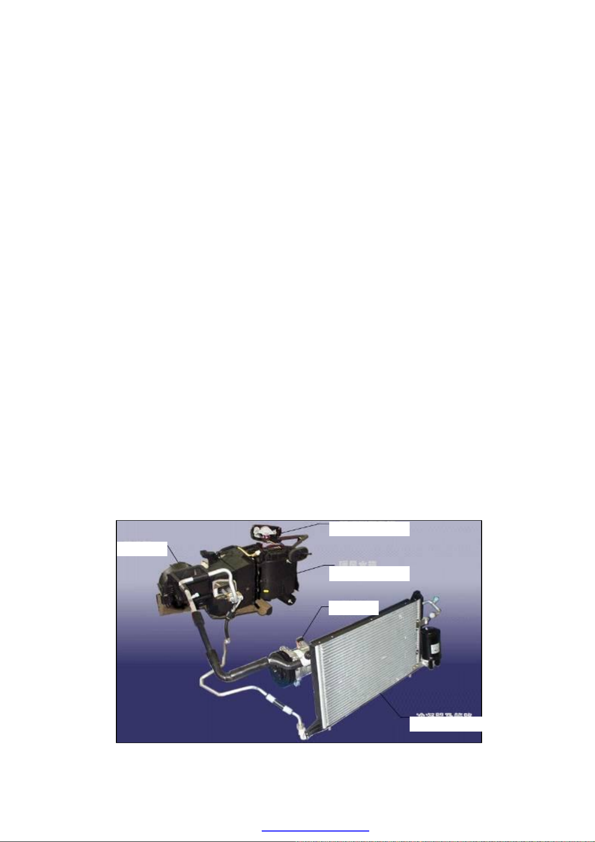
Evaporator
A/C Control System
Warm air radiator
Condenser
an
d Circuit
Compressor
AIR CONDITIONING SYSTEM OVERVIEW
Based on its function, the Chery A15LHD air
conditioning unit may be divided into such five
basic components as the refrigeration system,
heating system, ventilation system, control system
and air purification system.
1. Refrigeration system It is available to cool
the air inside the vehicle based on the refrigeration
principle of vapor compression refrigerator. The
temperature of evaporator as the cold source is
lower than the dew-point temperature of air, so the
refrigeration system also play the role of
dehumidification and air purification. The
refrigeration system of Chery's electronic fuel
injection type engine adopts the coolant R134a. As
shown in the figure, the refrigeration system
mainly consist of the compressor, condenser,
expansion valve, evaporator and etc. In the
evaporator, the coolant fluid absorbs the heat from
the air inside vehicle and is gasified to the
low-pressure, low-temperature coolant vapor, and
then is inhaled into the compressor.
U-2
PDF created with pdfFactory Pro trial version www.pdffactory.com
Page 3
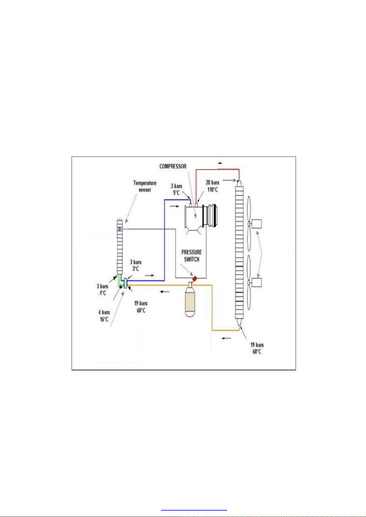
Condenser
Fan
The coolant vapor will be compressed by the compressor as the high-temperature,
high-pressure gas which enters into the condenser. In the condenser, the coolant is cooled by
the ambient air, and condensed into the fluid after emitting its heat outwards, then the
moisture content is filtered and removed from the fluid via the fluid reservoir. The
high-temperature, high-pressure coolant fluid is throttled down through the expansion valve
(installed in the inlet pipe of evaporator) to reduce its pressure and temperature, and then the
fluid enters into the evaporator. The low-temperature and low-pressure coolant fluid also
absorb the heat from the inside of vehicle, and gasifies again to the low-temperature and
low-pressure coolant vapor, and then is inhaled into the compressor. In such a manner, the
coolant cycles recurrently to make the indoor temperature of vehicle reduce. The pipelines
for coolant are shown in the figure below:
Compresso
Evaporator
Drying
Expansion
Valve
Bottle/Collector
2. Heating system It adopts the engine coolant as the heat source and introduces the
coolant into the radiator located at the compartment to heat the indoor air via the blower, and,
at the same time, it is also used to defrost and defog the front windscreen.Chery A15LHD’s
air conditioning unit adopts the reheating mixed type unit, the heating system of which is
used not only to individually heat the circulating air from the inside of vehicle or the fresh air
from the outside, but also to firstly cool these two kinds of airs and then heat the whole or
part to obtain the air temperature required. It is available to dehumidify the air, and also to
filter the air so as to get the clean air with desired humidity.
U-3
PDF created with pdfFactory Pro trial version www.pdffactory.com
Page 4
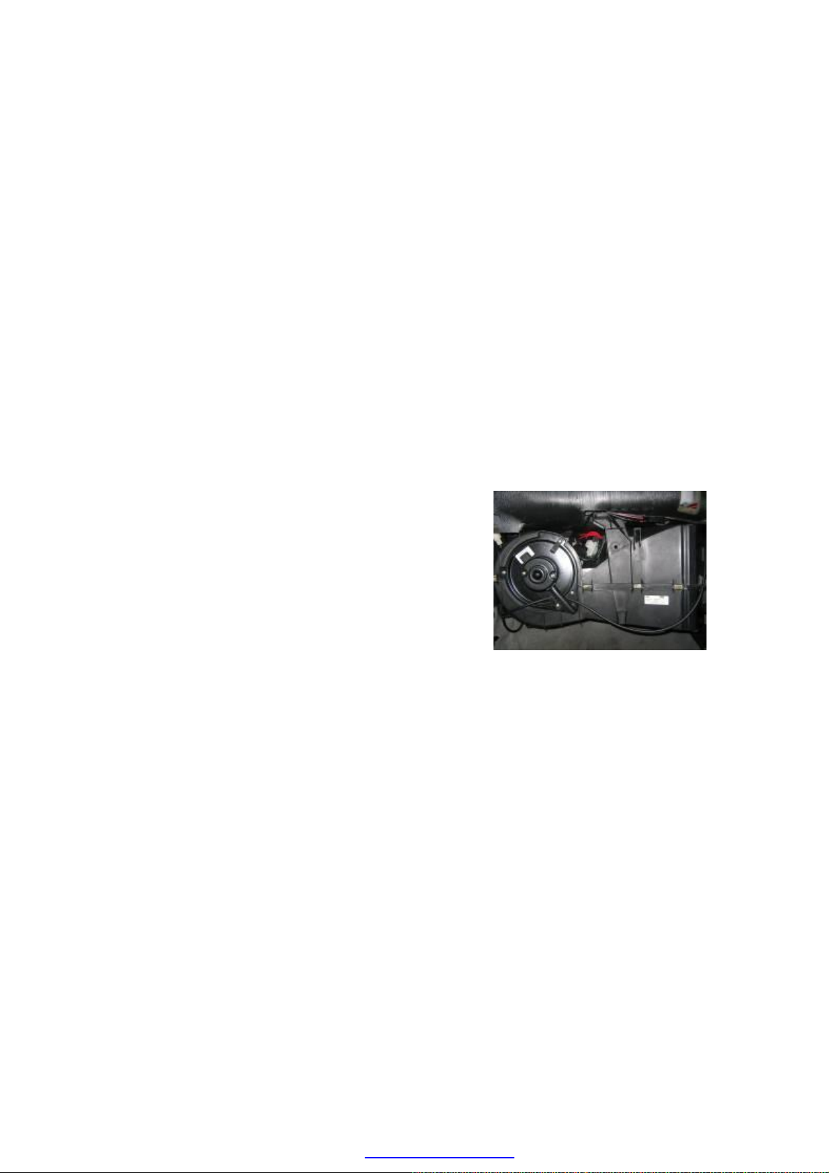
3. Ventilation system Apart from the cool and heat the air inside the vehicle, the
centrifugal blower is also used to change and ventilate the air inside the vehicle. The
ventilation system consists of the air filter, air inlet, air duct, vent and etc. The system
introduces the fresh air from the outside of vehicle into the inside while the ventilation and
discharge port extracts the vitiated air from the inside to the outside. Chery A15LHD adopts
the natural ventilation and forced ventilation. The open/close fresh air inlet is controlled by
the fresh/circulating air vacuum valve.
During the natural ventilation, the fresh air enters into the vehicle from the air inlet fixed
under the front windscreen (positive pressure area), and gets into the trunk from the seat belt
notch on the trunk cover, then passes across the vents (negative pressure area) on the body
rear skirt, trunk lining, rear side beam and finally discharges to the atmosphere. Due to the
movement of air in the rear body compartment, it plays a good role to defrost the rear
windows. In addition, the whole process is conducted without pressure, so the air changing
doesn’t create any noise and has nothing with the driving speed.
And during the forced ventilation, in case that the fresh air doesn’t pass through the heating
radiator (the mixed gate closed) after the air is pressurized by the blower, the air will enter
into the vehicle via all air ducts, and then discharge along the same route as that of natural
ventilation to the atmosphere.
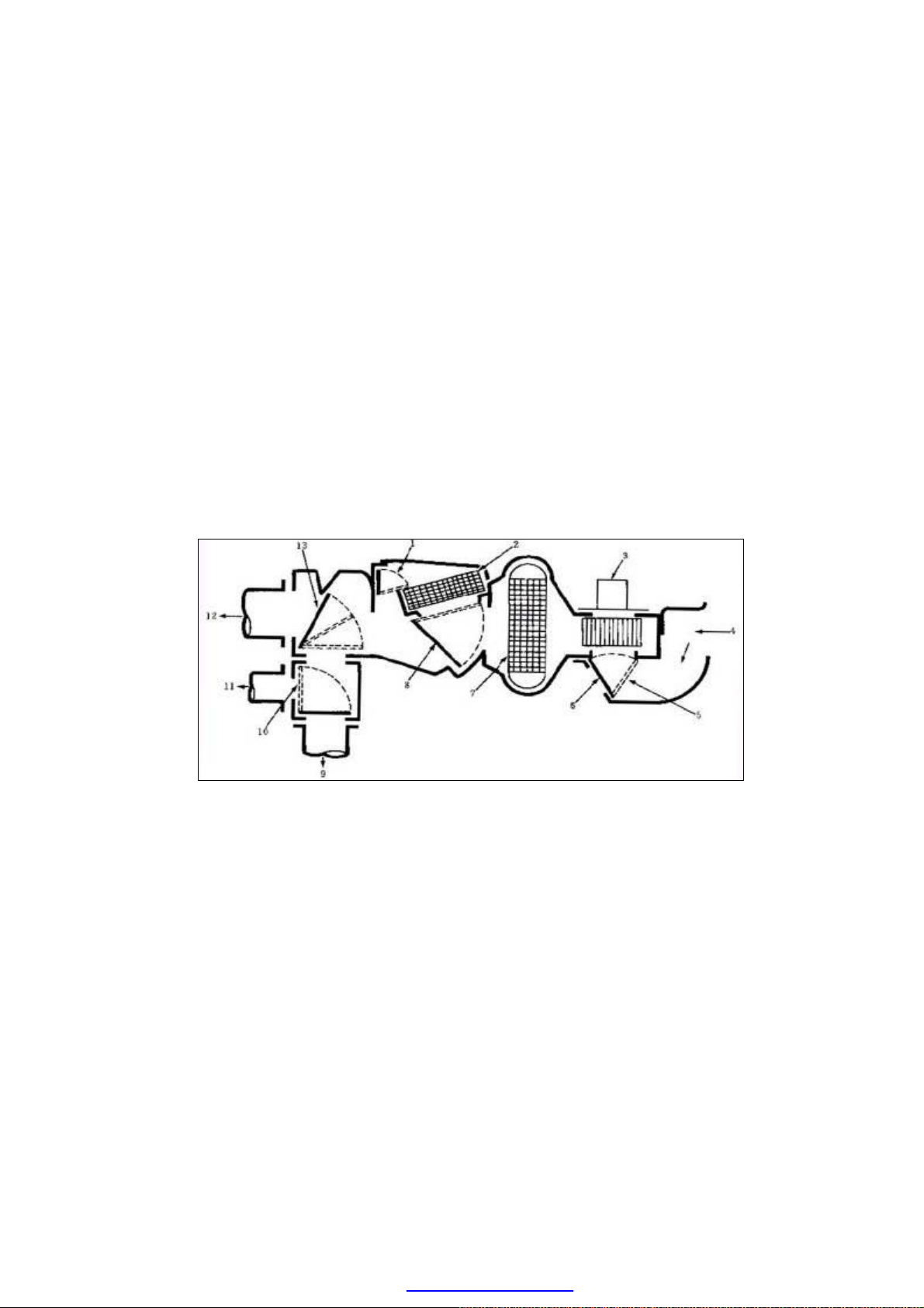
An individual type casing system with blower
1. Restrictor damper 5. Fresh/recirculated air door 9. To panel
2. Heater core 6. Recirculated air 10. A/C defrost damper
3. Blower motor 7. Evaporator core 11. To defroster
4. Fresh air 8. Air mix damper 12. To bottom outlet
U-4
PDF created with pdfFactory Pro trial version www.pdffactory.com
Page 5
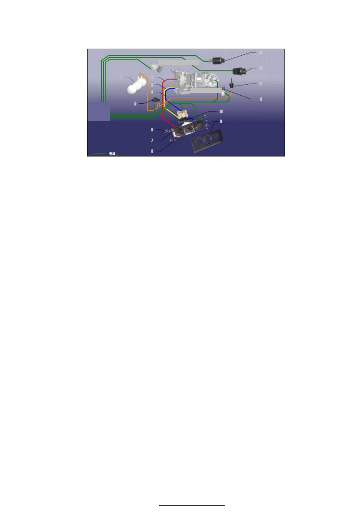
Air-Conditioner Compressor
Air-Conditi
E
vaporator Assembly
on Harness
4. Control system The control system mainly consist of the electrical component, vacuum
hose and control mechanism. On one side, it is available to control the temperature and
pressure of refrigeration and heating system, and, on the other side, it is also used to control
the temperature of air inside the vehicle, the blowing rate and direction.
5. Air purification system The air purification system mainly indicates the dust filter,
which is used to filter the outside air inhaled, and continuously discharge the vitiated air
generated inside the vehicle to make the air inside the vehicle clean and hygienic.
U-5
PDF created with pdfFactory Pro trial version www.pdffactory.com
Page 6
REFILLING OF REFRIGERANT AND REFRIGERANT OIL
Caution:
· If there are some moist materials or other
foreign materials circulating in the
refrigeration system, the cooling
performance of the refrigeration system will
considerably decrease and generate the
abnormal noise. So, after any refrigeration
and circulation part is removed, the
openings shall be immediately plugged to
avoid the entrance of moist materials or
other foreign materials.
· If the service reservoir is used to refill the
refrigerant, it is very dangerous to open the
valve located at engine high pressure side.
During the operation, the pressure inside the
service reservoir will rise, which may cause
the explosion of the reservoir, what’s more,
the metal fragment from explosion and the
refrigerant sputtered will be serious harmful
to the operators. Thus, it is recommended to
pay more attention to the close of the
high-pressure-side valve during the course
of engine operation.
Low
Low
pressur
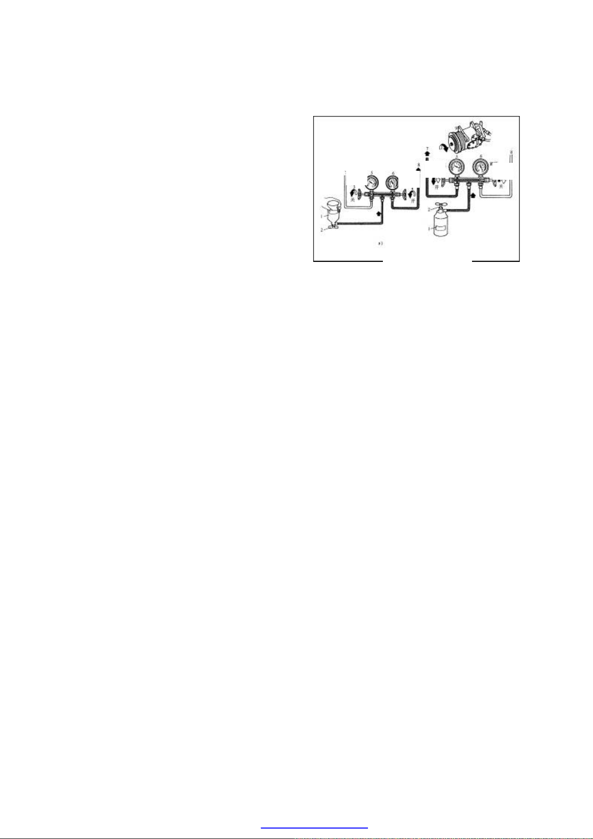
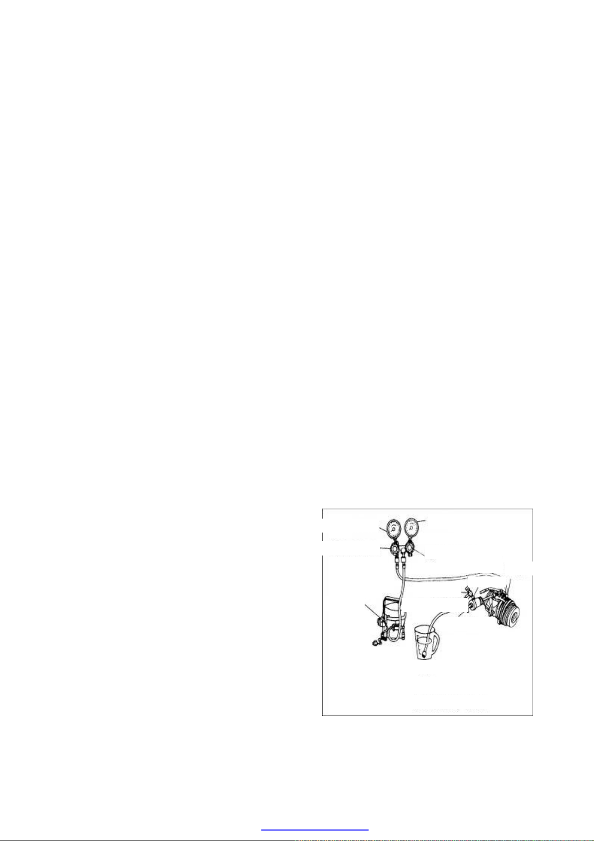
Charging the refrigerant
1-Refrigerant tank
2-Unlock valve
3-Low-pressure manual valve
4-High-pressure manual valve
5-Low-pressure gauge
6-High-pressure gauge
7-Connect to low-pressure service valve hose
8-Connect to high-pressure service valve hose
9-A/C compressor
High
pressur
pressur
High
pressur
Caution:
· Take care not to exceed the starndard
value(s) specified in the technical
specification during refilling the refrigerant
into the refrigeration system. If exceeding
the standard values, it will considerably
reduce the efficiency of the A/C system, and
even damage the refrigerant recirculation
parts.
· In accordance with the regulation, the
refrigerant shall be refilled from the
high-pressure side at all time. If it is refilled
from the low-pressure side, the valve leaf of
A/C compressor will loosen and give off the
abnormal noise.
U-6
PDF created with pdfFactory Pro trial version www.pdffactory.com
Page 7
1. Precautions for Refrigerant Concerned
(1) To avoid the refrigerant contacting with
your skin, wear rubber gloves and safety
goggles while handling the refrigerant.
(2) Handle the refrigerant concerned at a well
ventilated location. Since the refrigerant is
a colorless gas at room temperature and its
density is greater than that of air, the
refrigerant will deposit in the maintenance
location, which may easily cause the
maintenance personnel choked.
(3) Do not allow the refrigerant to contact with
fire. Otherwise it may generate the toxic
gas.
(4) The O-ring can be applied once only.
(5) Chery model-A15LHD adopts the
refrigerant R134a which cannot be
interchanged with R12. Also compressor
oils cannot be mixed. During the course of
handling, any tool that has touched certain
kind of refrigerant must not touch any other
kind of refrigerant.
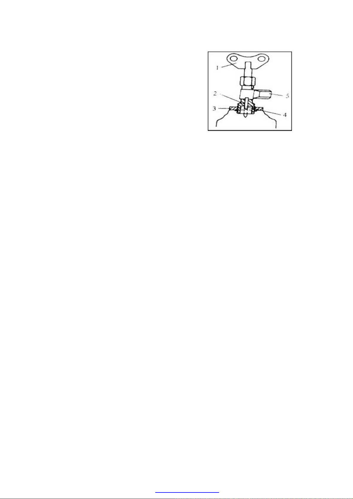
Refrigerant Tank Unlock Valve
1-Butterfly Handle
2-Refrigerant Tank Refilling Valve
3-Plate-shaped Nut
4- Needle Valve
5-Refilling Valve Joint
2. Method to Refill Refrigerant
If the 400g tanked refrigerant is required, a
refrigerant tank unlock valve shall be applied
(shown in the figure). The operation
procedures are as follows:
(1) Before the unlock valve is installed on the
refrigerant tank, turn the butterfly handle 1
in the counterclockwise direction till the
needle valve returns back completely.
(2) Turn the plate-shaped nut 3 in the
counterclockwise direction to lift it up to
the highest position, and then tighten the
valve and the dummy club at the center of
refrigerant tank.
(3) Install the intermediate filling hose of
manifold pressure gauge on the joint 5, and
then turn the plate-shaped nut in the
U-7
PDF created with pdfFactory Pro trial version www.pdffactory.com
Page 8
RECEIVER
SEVICE VALVE
clockwise direction and tighten it by hand
as possible.
(4) Turn the butterfly handle 1 in the
clockwise direction to make the valve
needle 4 in its front end punch a small hole
in the dummy club of refrigerant tank.
(5) Turn the butterfly handle 1 in the
counterclockwise direction, which the
refrigerant will flow into the manifold
pressure gauge along the charging hose.
(6) Then turn the butterfly handle 1 in the
clockwise direction to the lowest position,
and it can close down the refrigerant tank
again. However, do not detach the unlock
valve, otherwise the refrigerant inside the
tank will leak out.
3. Refrigerant Refilling Procedures
(1) Connect the manifold pressure gauge to
the refrigerant tank, shown in the picture
below.
(2) Unscrew the handle of unlock valve 2 in
the counterclockwise direction to enable
the refrigerant to enter the intermediate
charging hose. In this case, do not open the
handle valves in the both sides.
(3) Unscrew the nuts of intermediate hose of
manifold pressure gauge, and then tighten
the nuts of intermediate hose after the air
inside the intermediate hose are drained
when you see the white refrigerant gas
overflow and heard the “fizzle” sound.
(4) Turn on the high-pressure manual valve 4,
shown in the figure below, stand the
refrigerant tank 1 upside down so as to let
the refrigerant in liquid-state charge into
the refrigeration system. In this case, do
not switch on the A/C unit to prevent the
refrigerant from returning back to the tank.
U-8
LOW-PRESSURE
SEVICE VALVE
HIGH-PRESSURE
REFRIGERATION DEVICE
RECYCLING
PDF created with pdfFactory Pro trial version www.pdffactory.com
Page 9
200 g or more refrigerants shall be charged
every time, and turn the compressor
several times by hand after the completion
of charging.
(5) Turn off the high-pressure manual valve 4,
shown in the figure below, and turn on the
low-pressure manual valve 3 to let the
refrigerant in gas-state charge into the
refrigeration system. The refrigerant
charged from the low-pressure manual
valve must be gas-state. If it is liquid state,
the liquid hammer phenomenon may
appear to damage the compressor. Turn off
the low-pressure manual valve when the
reading of low-pressure gauge reaches
2.8X10⁵ Pa.
Refrigerant Refilling
Regulated amount:R134a,850±25g
4. Leak Check of Refrigeration System
Three effective methods can be used to check
the air tightness of refrigeration system: check
with electronic leak detector, soap solution and
halogen leak detector.
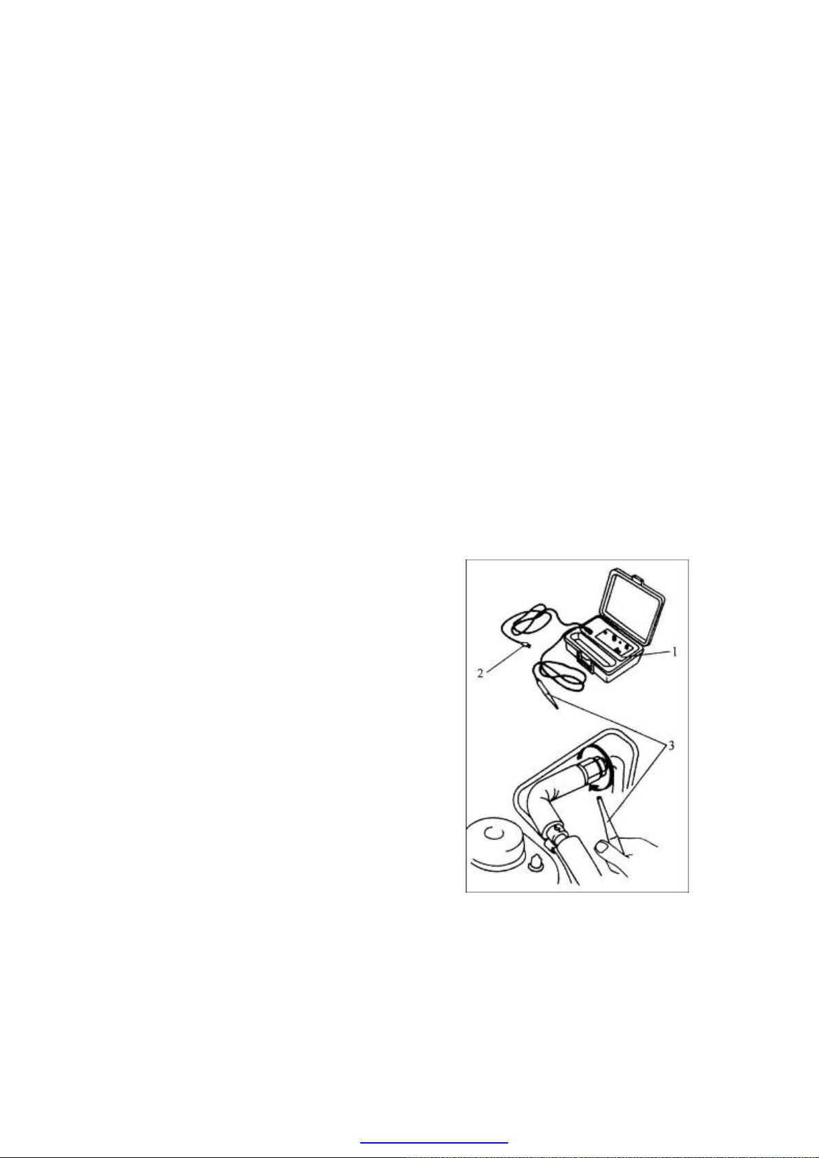
1) Check with Electronic Leak Detector
As shown in the figure, connect the power
supply connector 2 of electronic leak detector
1 to the power supply, and move probe 3
slowly (30 mm/s), which should be placed 3
mm away from the check point. And if any
alarming sound is emitted, it means there is a
leak phenomenon occurred at that place.
2)Check with Soap Solution
Apply the soap solution to the possible leak
position. Observe whether air bubbles appear.
If there are air bubbles, it indicates a leaking
accident occurs.
3)Check with Halogen Leak Detector
The inspection procedure is described below:
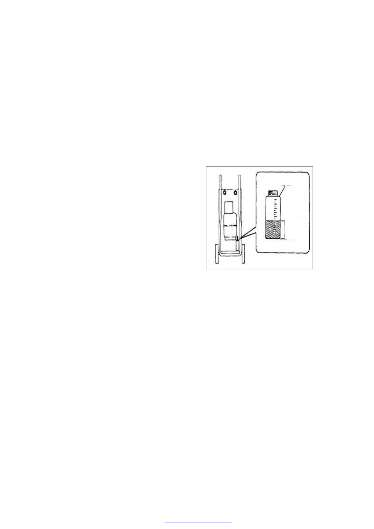
(1) Check the liquid propane capacity in the
1. Electronic leak detector.
2. Power supply connector.
3. Probe
If the leakage occurs at the joints
of refrigeration pipes, the relevant
O-rings shall be replaced.
U-9
PDF created with pdfFactory Pro trial version www.pdffactory.com
Page 10
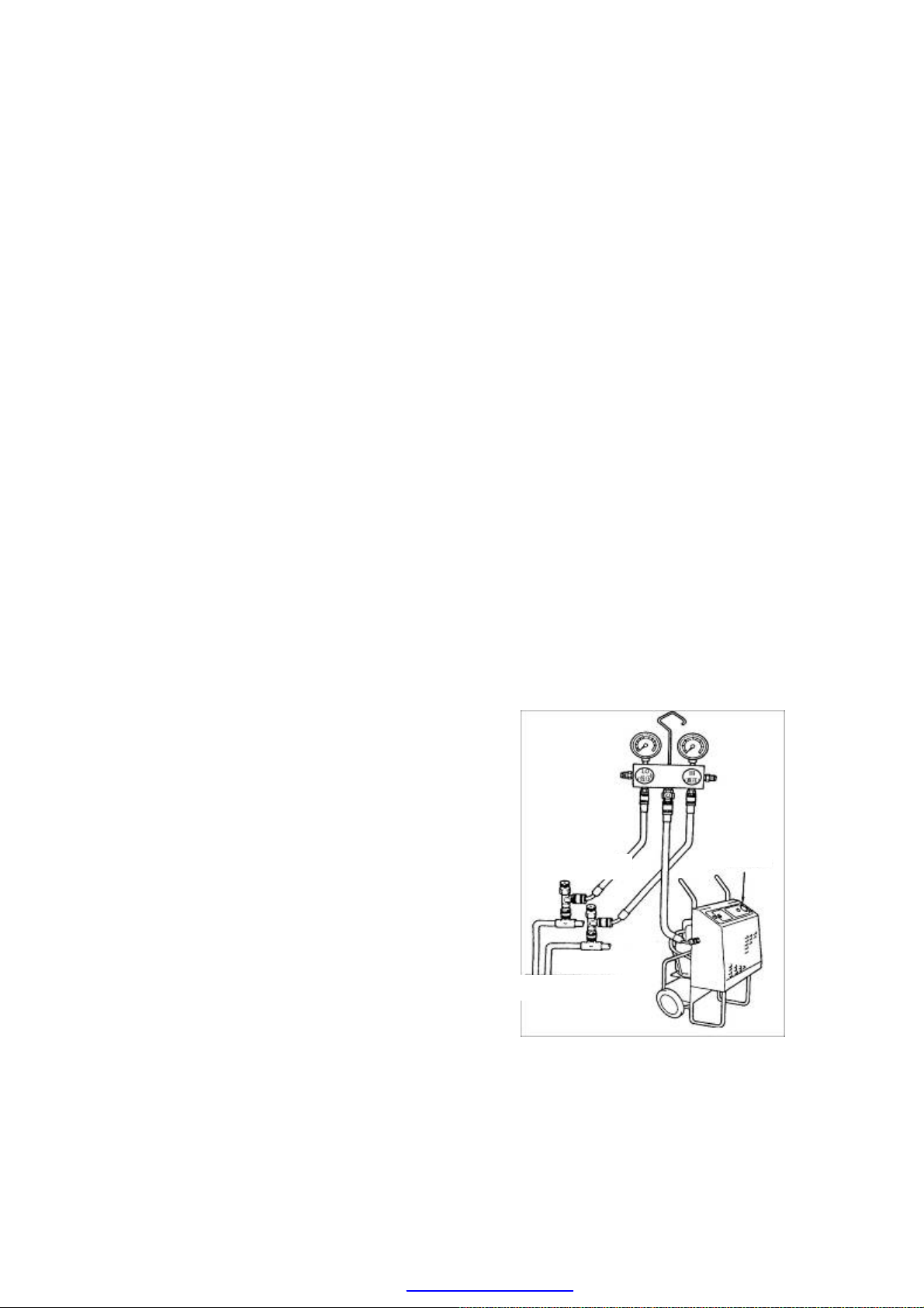
Vacuumizing and Charging the Refrigeration Oil
reservoir.
(2) Tighten the propane reservoir 16 to the
leak detector.
(3) Insert a lighting match into lighting device
9, and then slowly turn the adjusting
handle 14 in the counterclockwise
direction till the torch is lit.
(4) Adjust the flame to smallest. The smaller
the flame, the more sensitive to the leak of
refrigerant.
(5)Move suck pipe 3 to the possible leak
position.
(6) Observe the change of flame color. The
flame has no color if there is no leakage.
The flame is tint green if there is very
small leakage or be blue if there is
relatively big leakage, and it will become
purple if there is too much leakage.
5. Methods of Refrigerant Oil Charging
There are two methods for refrigerant oil
charging: direct charging method and vacuum
inhaling method.
1)Direct charging
Remove the oil charging plug 1, and charge
the specified model of refrigerant oil.
2)Vacuum inhaling
Vacuumize the refrigeration system to 30psi,
and then start to charge the refrigerant oil, the
procedures of which are as follows:
(1) Turn off the high-pressure manual valve,
and turn off the auxiliary valve.
(2) Remove the high-pressure side hose from
the manifold pressure gauge, and insert
the hose into the oil cup.
(3) Turn off the auxiliary valve to inhale the
refrigerant oil into the refrigeration system
from the oil cup.
Low-pressure gauge
Low-pressure manual valve
Vacuum pump
High-pressure gauge
High-pressure manual valve
Low-pressure side hose
auxiliary valve
High-pressure side hose
High-pressure pipe
Oil cup
Air return
Air exhaust
(4) When the refrigeration oils in the cup are
nearly evacuated, immediately turn off the
U-10
PDF created with pdfFactory Pro trial version www.pdffactory.com
Page 11

auxiliary valve so as to prevent the air
from being inhaled into the system.
(5) Connect the high-pressure side hose joint
to the manifold pressure gauge, turn on the
high-pressure manual valve, and start up
the vacuum pump to vacuumize the
high-pressure side hose. And turn on the
auxiliary valve to vacuumize for the
system to 30psi, and then vacuumize 15
min again so as to remove the air entering
into the system together with the oils. In
this case, the refrigeration oils are in the
high-pressure side, and the oils will return
back to the compressor after the operation
of the system.
3)Type & amount of refrigerant oil charged
Regulated amount: SP10 type, 150ml.
It is unnecessary to charge the refrigerant oil
into the newly-mounted A/C system, and it is
required to complement some refrigerant oil
only when a certain part is needed to repair or
when the vehicle is driven to a specified
mileage.
The amount of implementing oil required
when replacing parts is as follows: Evaporator
and condenser: 30ml. Drier: 20ml. and pipe:
10ml.
U-11
PDF created with pdfFactory Pro trial version www.pdffactory.com
Page 12
6. Methods of Refrigerant Vacuumizing
It is difficult to pump out the water from the
refrigeration system when vacuumizing. But
the vacuumizing can reduce the fluidization
point of water after the vacuum is generated in
the refrigeration system, which enables the
water to boil at the lower temperature, and
pump out it in the form of steam from the
system.
Conduct the leak check firstly before
vacuumizing. If vacuumizing without the leak
check, it is difficult to find out the leaking
position after vaccumizing when there is a
certain leakage phenomenon.
The purpose of vacuumizing is to further check
the air tightness of the refrigeration system
under the vacuum condition, and prepare for
the system’s refrigerant charging. Its
procedures are as follows:
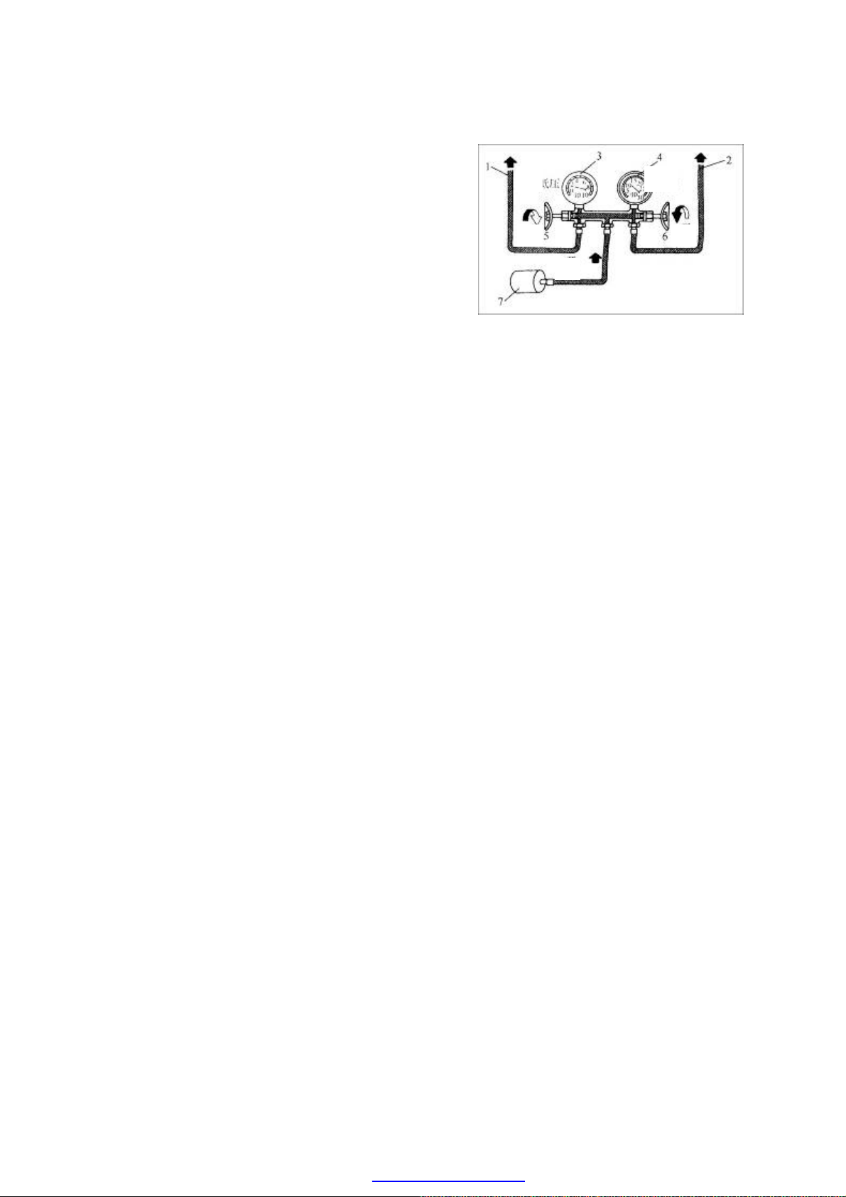
(1) Connect the high-pressure gauge hose to
the high-pressure service valve joint of
refrigerant tank, shown in the figure below,
connect the low-pressure gauge hose to the
low-pressure service valve joints on the
pipe from the evaporator to the A/C
compressor, and connect the intermediate
hose to the interface of vacuum pump.
(2) Turn on the high- and low-pressure valves
of manifold pressure gauge, and start up
the vacuum gauge.
(3) The vacuum pump works for at least 15
min to make the vacuum reading of
low-pressure gauge below 30psi . If the
vacuum reading can’t be obtained, turn off
the manual valves at the high- and
low-pressure sides, stop vacuumizing, and
check the leaking position.
(4) Turn off the valves, and the gauge needle
doesn’t return back within 10 min, which it
is called the vacuum leakage check method.
If the vacuum down, it shows that there is a
leaking position which can be found out by
using a leakage detector.
(5) If the gauge needle doesn’t considerably
1- Connect to low-pressure service valve hose
2- Connect to high-pressure service valve hose
3-Low-pressure gauge
4-High-pressure gauge
5-Low-pressure manual valve
6-High-pressure manual valve
7-Vacuum pump
Low
pressu
On
On
Vacuumizing
High
pressure
On
U-12
PDF created with pdfFactory Pro trial version www.pdffactory.com
Page 13
return back within 10 min, it indicates that
the system is normal and the refrigerant can
be charged into the system.
(6) Restart the vacuum pump, and turn on the
low-pressure valve of the manifold
pressure gauge to continuously vacuumize
15 min. Then, turn off the low-pressure
valve to stop vacuumizing, and prepare for
charging the refrigerant.
7. Refrigerant Recycling Equipment Operation Guide
Recycle the refrigerant from the
refrigeration device
When the refrigerant is removed from the
OIL BOTTLE
refrigeration device under the following
conditions, a recycling receiver shall be
applied to recycle the refrigerant.
Before the components on the refrigerant pipe
are replaced.
DRAINED
OIL
QUANTITY
When moisture or air enters into the
refrigerant pipe.
When excessive refrigerants are charged into
the system.
WARNING:
(1) When the recycling receiver is required, take care to operate it according to the
requirements of device manufacturer's instructions.
(2) After the completion of recycling work, measure the level of compressor oil recycled so
that the same quantity of oils are added to the refrigeration device in the future.
Operation guide for refrigerant recycling receiver
1. Install the manifold pressure gauge kit on the service valve.
2. Recycle the refrigerant from the refrigeration device.
(a) Connect the intermediate hose to the recycling receiver.
(b) Operate the recycling receiver.
(c) Open the manual high- and low-pressure valves on the refrigeration pressure gauge kit.
1. After the completion of recycling work, turn off the recycling receiver.
2. Remove the manifold pressure gauge kit from the service valve.
U-13
PDF created with pdfFactory Pro trial version www.pdffactory.com
Page 14
A/C SYSTEM COMPONENTS
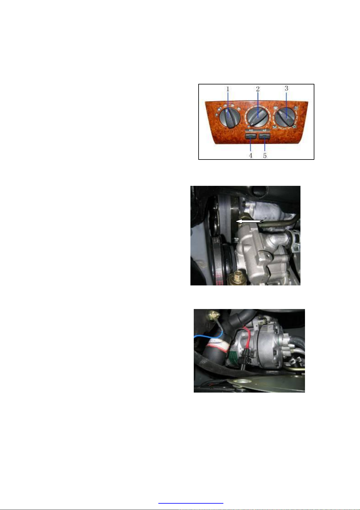
1. Function description of A/C control panel
(1) Blower switch
(2) Temperature control switch
(3) Air-flow distribution switch
(4) A/C ON/OFF
(5) Internal circulation switch
2. Removal/Installation of A/C compressor
(1) Drain off the coolant (see the coolant
recycling procedure)
(2) Loosen the drive belt, and remove it
(3) Remove the air filter and generator
(4) Remove the refrigerator pipes, and pull out
the electromagnetic clutch connector
(5) Remove the two bolts (M10*110) (with
tightening torque of 45±5N·m) used to
secure the compressor and its support.
(6) Install it in the reverse order of removal
Compressor Position and Related
Performance Parameters:
Chery A15LHD with the electronic fuel
injection type engine adopts the SD7V16 type
compressor, the performance parameters of
which are shown in the table below.
U-14
PDF created with pdfFactory Pro trial version www.pdffactory.com
Page 15

Swash Plate
Number of cylinders 7
Cylinder diameter (mm) 29.3
Travel (mm)
max
min
Displacement (cm³/r)
max
min
Allowable maximum instantaneous speed
34.2
2.2
161.3
10.4
8000
(r/min)
allowable maximum continuous speed
7000
(r/min)
Coolant R134a
Refrigerant oil (cm3) 115±15
Electromagnetic clutch mass (kg) 2.2
Rated voltage (V) 12
Rated power (W) 48
U-15
PDF created with pdfFactory Pro trial version www.pdffactory.com
Page 16
The compressor is driven by engine crankshaft pulley via the M belt. When the shift lever
on the A/C control mechanism is shifted to the refrigeration position, the electromagnetic
clutch of A/C compressor engages, and the compressor pulley make the main shaft and
swash plate rotate and then pull the rocking plate to swing. The swinging of the rocking
plate pushes the piston to move, which creates the air pumping effect to compress the
low-temperature and low-pressure air-state coolant into the high-temperature and
high-pressure air-state coolant.
The motion parts of compressor are lubricated using the sputtered refrigerant oil and the oil
in coolant. During the operation of compressor, due to the rotation and swing of the swash
plate, the refrigerant oil will be sputtered to anywhere. In addition, due to the intersolubility
of coolant and oil, when the coolant flows into the compressor, it also carries a part of
refrigerant oil which is available to lubricate the motion parts inside the compressor.
ADJUSTMENT OF ELECTROMAGNETIC CLUTCH
1. Use a thickness gauge to measure the clearance between the platen and A/C compressor
pulley.
2. Check whether the clearance is in the range specified by the technical specification.
• If it is found that the result doesn’t conform to the requirement of technical specification,
remove the platen, and use one or several shims to adjust the clearance.
Clearance:
0.6mm±0.2mm
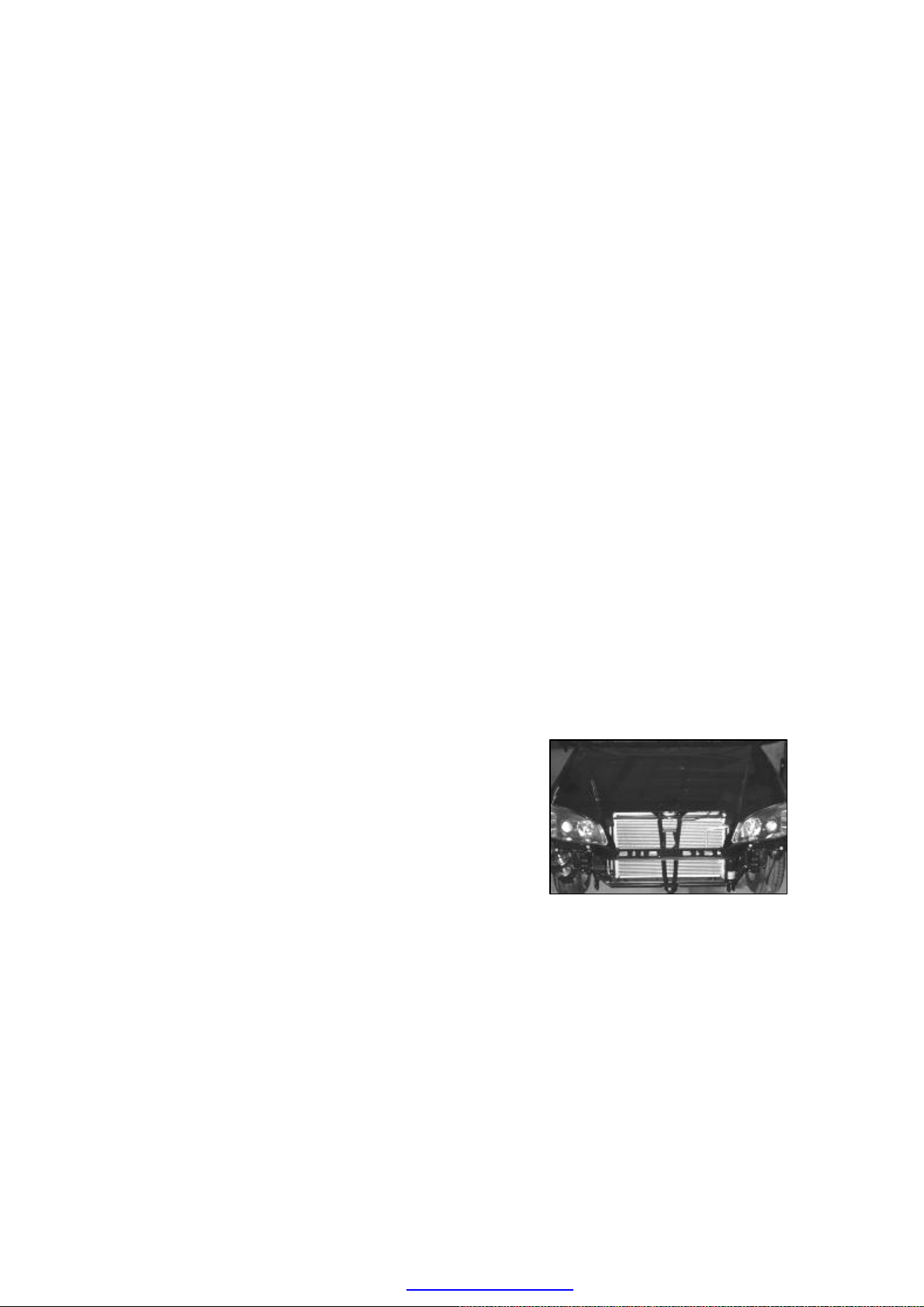
3. Removal/Inspection of condenser
(1). Drain off the coolant from the system (see the
coolant recycling procedure)
(2). Remove the front bumper and headlamp crossbeam
assy.
(3). Remove the fluid reservoir and the refrigeration
pipes connecting to the condenser.
Check the condenser:
(1) Check the crack, damage or oily fluid leakage.
·Replace the condenser if any failure above occurs.
(2) Check whether the fender position is blocked by dust
or not.
·Clean it if blocked.
(3) Check the bent condition of fender position.
·Use a flat headed screwdriver to straighten the fender
U-16
PDF created with pdfFactory Pro trial version www.pdffactory.com
Page 17
position if the bent is found.
Installation of Condenser
(1) Use some self-tapping screws to secure the
condenser and radiator, and assemble the related
screw bush and spacer, with the tightening torque
of 6±0.6N·m;
(2) Use the bolts (M6) and spacer to secure the
condenser support on the front crossbeam, with the
tightening torque of 1.5±0.15N·m;
(3) Assemble the integrated condenser-radiator into the
related fixing holes;
(4) Use spacer, shim block and two nuts to fasten the
condenser and front crossbeam, where the tightening
torque of nut is 1.5±0.15N·m.
The condenser is designated to cool the coolant vapor
discharged from the compressor and condense the vapor
to make it give off its heat and become to the coolant
fluild.
Chery A15LHD adopts the serpentine condenser, as
shown in the figure. The condenser is secured with
engine radiator in a row, and there is an axial fan, which
is driven by a DC motor, behind them to forcedly cool
the condenser and radiator.
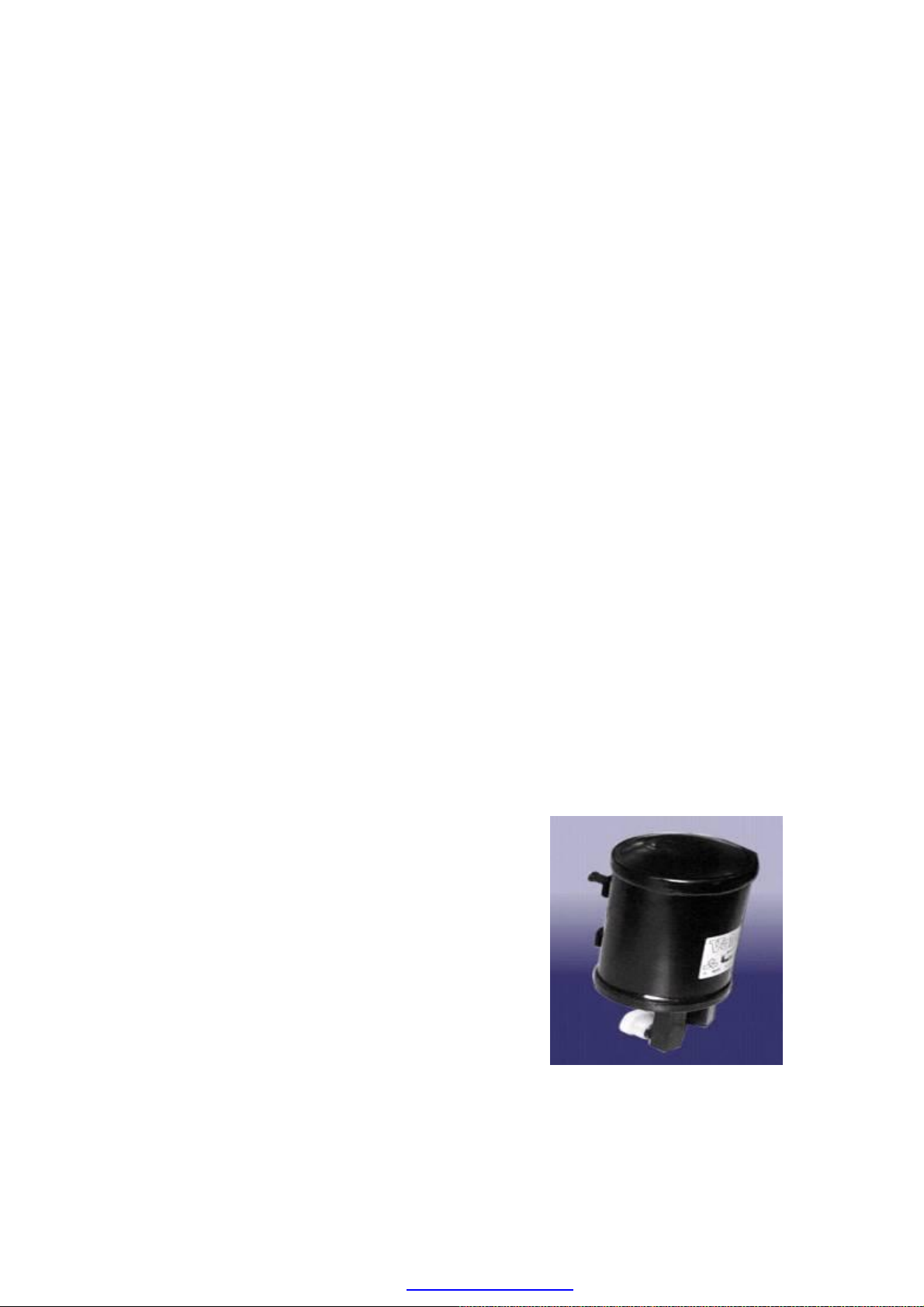
Introduction to the fluid reservoir:
Removal/Installation (see the Removal of Condenser)
Chery A15LHD’s fluid reservoir is located under the
condenser (i.e., the outlet of condenser), the structure of
which is shown in the figure.
In fact, the fluid reservoir is a pressure container used to
store the coolant, and it is available to delivery the
fluid-state coolant to the expansion valve at a specified
flow rate. The filter screen of fluid reservoir is applied to
filter the all kinds of foreign materials from the coolant.
The drying agent silicon oxide with powerful water
absorptivity is filled in the drying unit, which is used to
absorb the water content in the coolant. In addition, a
fusible plug is also installed on the reservoir. If the poor
heat emission of condenser or other causes result the
rapid rise of temperature and pressure of the
U-17
PDF created with pdfFactory Pro trial version www.pdffactory.com
Page 18
refrigeration system, the fusible plug will metal so as to
drain off the high-temperature and high-pressure coolant
when the temperature and pressure inside the reservoir
reach the specified value, which protects the
refrigeration system.
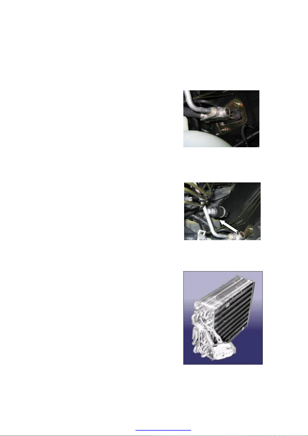
4. Introduction to the expansion valve and pressure
switch
1) Expansion valve
Chery A15LHD adopts the traditional thermo-expansion
valve, as shown in the figure, fixed on the inlet/outlet
pipes of evaporator.
The temperature sensor inside the expansion valve
adjust the opening of ball valve in accordance with the
temperature of coolant located at the evaporator outlet,
the purpose of which is to control the flow rate of
coolant.
2) Pressure switch
Chery A15LHD’s A/C pressure switch adopts the
dual-pressure (high and low pressures) and four-wire
pressure switch which is installed on the high pressure
pipe located at the front end of expansion valve, with 50
PSI or more of low-pressure CLOSE operation and
220 PSI or more of high-pressure CLOSE operation
5. Removal/Installation and inspection of evaporator
(1) Drain off the coolant from the system (see the
coolant recycling procedure)
(2) Remove the expansion valve
(3) Remove the instrument panel (see the
Disassembly/Assembly of Instrument Panel)
(4) Remove the control panel trim plate, and 4
self-tapping screws used to secure the control panel
and console. (tightening torque of 1.5±0.2N·m)
(5) Remove 1 bolt (M8*25) and 4 nuts secured with the
steering crossbeam and front side respectively
(tightening torque of 3.5±0.2N·m) from the fixed
evaporator.
(6) Remove the four bolts from the evaporator.
Inspection of evaporator:
U-18
PDF created with pdfFactory Pro trial version www.pdffactory.com
Page 19
(1) Check the crack, damage or oily fluid leakage.
·Replace the evaporation unit if any failure above
occurs.
(2) Check the bent of fender.
·Use a flat headed screwdriver to straighten it if a bent
is found.
The Chery A15LHD adopts the tube-fin type evaporator
which is installed in the air conditioning unit assy. under
the instrument panel.
The function of evaporator is opposite to that of
condenser. After expanded in the expansion valve, the
coolant fluid absorbs the heat inside the vehicle from the
evaporator, and evaporates to the coolant gas, then
enters into the compressor to circulate.
Introduction to the evaporator temperature sensor
(thermostat):
The evaporator temperature sensor used by the Chery
A15LHD is the heat-sensitive tube mechanical type
temperature regulator, which is closed when the working
temperature is adjusted to 4 or more while ℃
disconnected when adjusted to 4 or below. Its ℃
installation position is just under the evaporator, as
shown in the figure.
The tightening parameters of A/C pipe fasteners
Inner hexagonal head bolt (M10) secured in the
compressor: 30N•m;
Inner hexagonal head bolt (M6) secured in the
expansion valve: 7N•m;
To connect with condenser inlet pipe and tighten the
nuts: 32 N•m;
To connect with condenser outlet pipe and tighten the
nuts: 11.9 to 13 N•m;
U-19
PDF created with pdfFactory Pro trial version www.pdffactory.com
Page 20

FAILURES AND SHOOTING ANALYSIS SHEET
1. Precautions on A/C system installation
(1) For the pipes fixed using the fixing nuts, two
wrenches must be applied to ensure that the
pipes don't deform or break;
(2) Do not use the compressed air to clean the pipes,
and the nitrogen or coolant gas is available;
(3) Correctly assemble it, and check the tightening
torque of all connections as required;
(4) Check all parts to ensure that they aren’t damaged
and all adjacent parts don’t interfere each other;
(5) Conduct the leakage test to ensure there is no
leakage in the A/C system.
U-20
PDF created with pdfFactory Pro trial version www.pdffactory.com
Page 21

PRECAUTIONS ON THE SECURITY OF A/C SYSTEM
Coolant treatment
1. The operator shall pay more attention to prevent the coolant fluid from spraying into
your eye or on your skin because the fluid-state coolant is very dangerous. Only one drop
of coolant will cause your skin to be damaged partially if it drops up the skin of the skin.
You must put on your grooves and protective goggles. When the coolant sprays into your
eye or on your skin
(a) Use the cold water to clean those parts
(b) Do not wipe your eye or skin
(c) Immediately get to a hospital to have a professional personnel treat it.
It is recommended to use such equipment as the recovered, recycling, or reused equipment. If
there is any emergency system failure, it is recommended that the equipment is placed on a
ventilation treatment site before the implementation of the equipment maintenance service.
2. Do not dispose the coolant located at a closed place or near fire. If the coolant gas contacts
with sparks or the similar heat source (such as: cigarette or heater), it will generate the toxic
gas.
Storage of coolant
A6E851001039W02
1. The coolant shall be stored in the high-pressure resistance equipment, and take care to
slightly place the fluid reservoir to prevent the reservoir from being impacted by some sharp
materials. Heating the coolant fluid reservoir or taking it near the fire will make it explode,
and the metal fragment generated and the sputtered fluid-state coolant will cause the serious
injury to people. It is recommended to store the coolant under the environment of 400C
(1040F) below.
Safety Notices
1. Do not sit inside the vehicle which operates at the idle speed for a long time, and also do
not leave a child in the vehicle.
2. Switchover the air conditioner to the external circulation mode and inhale the fresh air
into the vehicle from the outside, and change the blower switch to the High-Speed
position when the engine has operated in an unclosed environment for a long time.
3. Avoid the open of luggage boot cover during driving because the gas emitted from the
engine may enter into the vehicle. If the boot cover must be opened, please close all
windows, and change the air conditioner to the external circulation mode to inhale the
fresh air into the vehicle from the outside.
4. Do not open the high-pressure valve of manifold pressure gauge during the operation of
compressor. If the high-pressure valve is opened, the coolant will flow in the reverse
direction and cause the fluid reservoir to be broken.
U-21
PDF created with pdfFactory Pro trial version www.pdffactory.com
Page 22

Coolant shortage treatment
·If it is found that there is the coolant shortage during checking the failure, it is
recommended to add the coolant. The reason is: there is the difference between the pressure
values indicated by the different pressure gauges, so it is difficult to add the coolant with
accurate quantity in accordance with the pressure reading. If the coolant added is excessive
or insufficient, it may cause a series of negative effects, such as: to damage the coolant
recycling parts, or, to reduce the refrigeration effect. Thus, if it is found that the coolant is
insufficient, it is recommended to completely drain off the coolant from the coolant
circulating pipes, and then add the specified quantity of coolant.
Compressor oil treatment
·For this model of vehicle, it is recommended to use the SP10 model compressor oil;
otherwise it may be available to regulate the compressor.
·Take care not to spray the compressor oil on the surface of the vehicle during the
maintenance operation. Thus, if this case occurs, immediately wipe and clean it, otherwise
the compressor oil will damage the paintwork on the surface of the vehicle.
·Engine oil shall absorb the moisture.
U-22
PDF created with pdfFactory Pro trial version www.pdffactory.com
Page 23
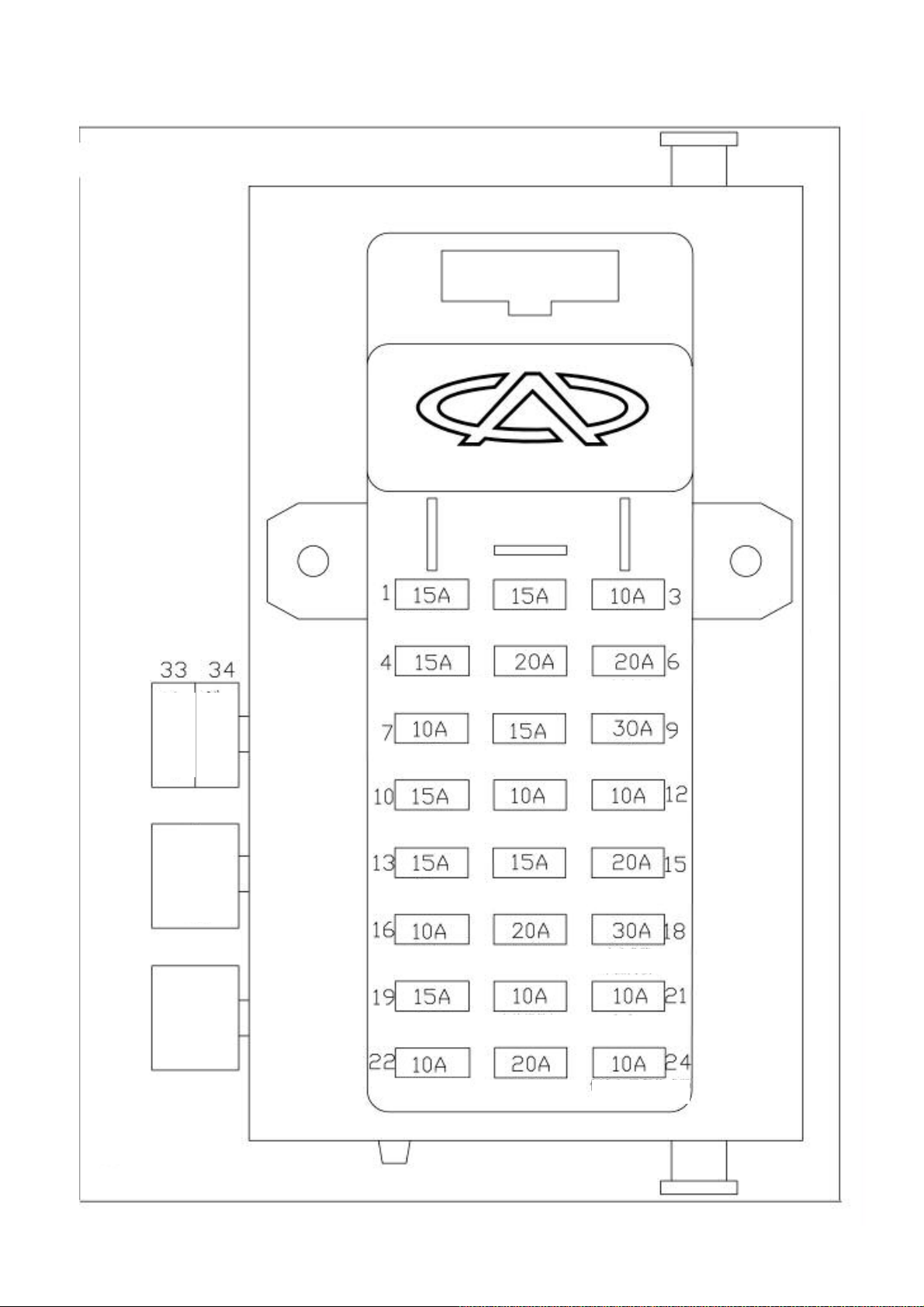
Relay
Layout Diagram Of Central Electrical Box
(Under The Steering Wheel)
A/C Clutch
ABS
Fuse
ABS
Fuse
Sunroof
,
Taxi
License Lamp
Ceiling Light
,
Trunk Lamp
,
Audio Equ ipment
Headlamp Switch
Rear W
indow Heating
Instr
ument
Wiper
A/C
Fog Lamp
Horn
Brake Lamp
Thermo
-
Sensitive Switch
Win do w R eg ul ato r
/Central Control Lock
Cigarette Lighter
Malfunction Alarm Lamp
Instrument
Back-Up Lamp
Mileage Sensor
Wiper Relay
Emergency
Alarm Relay
Burglar Alarm
Electric Rea rview Mirror
Page 24
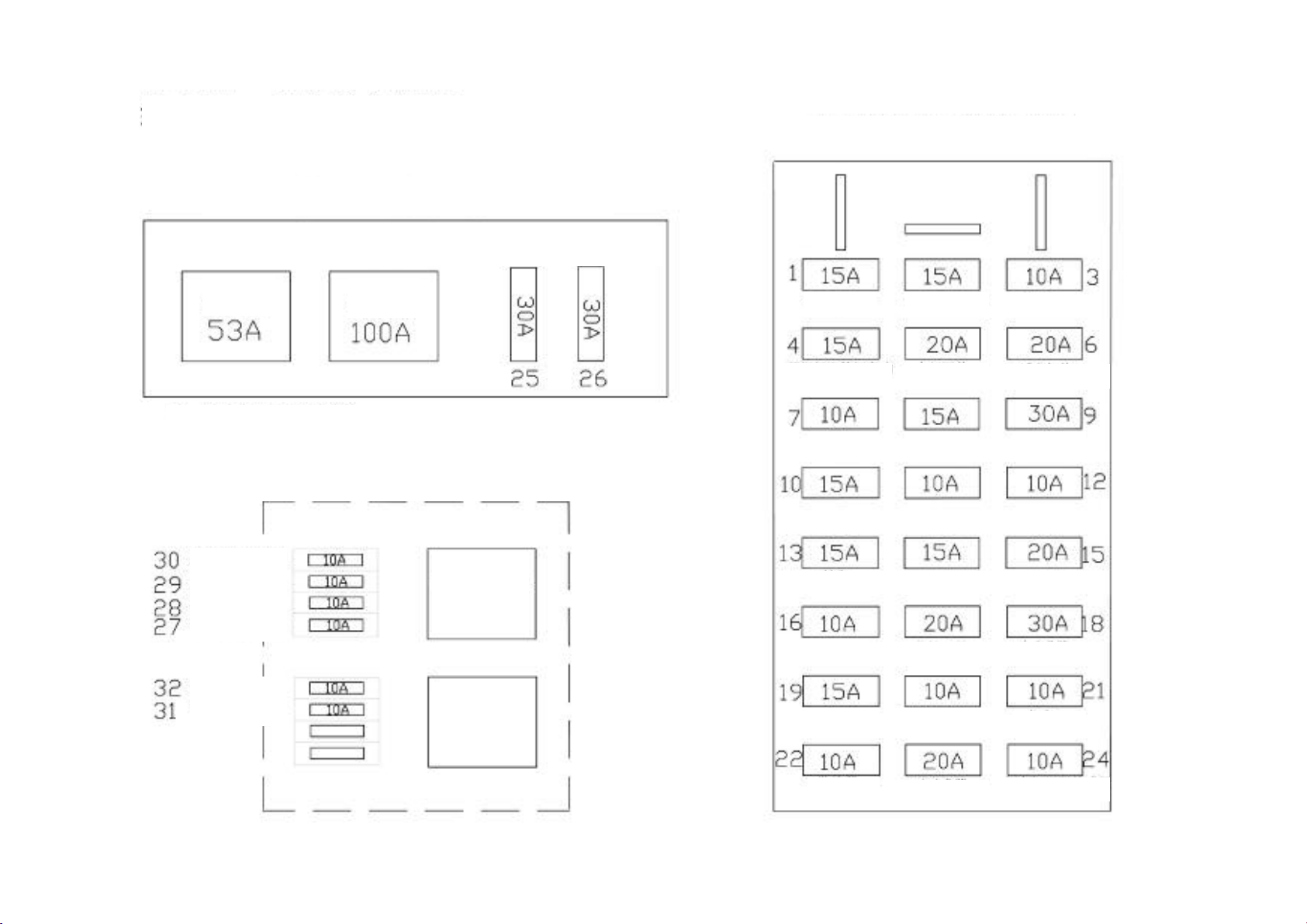
Fuse Layout Diagra
m Of Central Electrical Box
(Under The Steering Wheel)
A/C clutch
Sunroof, Taxi
License Lamp
Top LampTrunk Lamp
Fog Lamp
Window Regulator
Thermo
-
Sensitive Switch
Brake Lamp
Burglar Alarm
Window Regulation
Back-Up Lamp
mileage Sensor
Layout Diagram Of Relay
&
Fuse
Radiator Fan Control
(1)
Side Of Carwash Container
Low Speed
High
Speed
Low Speed
High
Sp
eed
Relay
Relay
Note: For Dual
-
Speed Fan, Use 50a Fuse For High Speed.
Layout Diagram (2)
Of Fuse In Relay Box
Right Of Front Engine Compartment
Fuse For Left High
Fuse For Left High
Fuse For Left
low
Fuse For
Right High
Fuse For Right
Fuse For
Right Low
Low And High
Beam Lamp
Position Light
Beam Lamp
Beam Lamp
Position Lamp
Beam Lamp
Beam Of
Headlamp
Relay
A/C
Relay
Audio Equipment
Instrument Wiper A/C
Horn
Cigarette Lighter Malfunction Alarm Lamp
Headlamp Switch
Rear Window Heating
Instrument
Page 25
Page 26

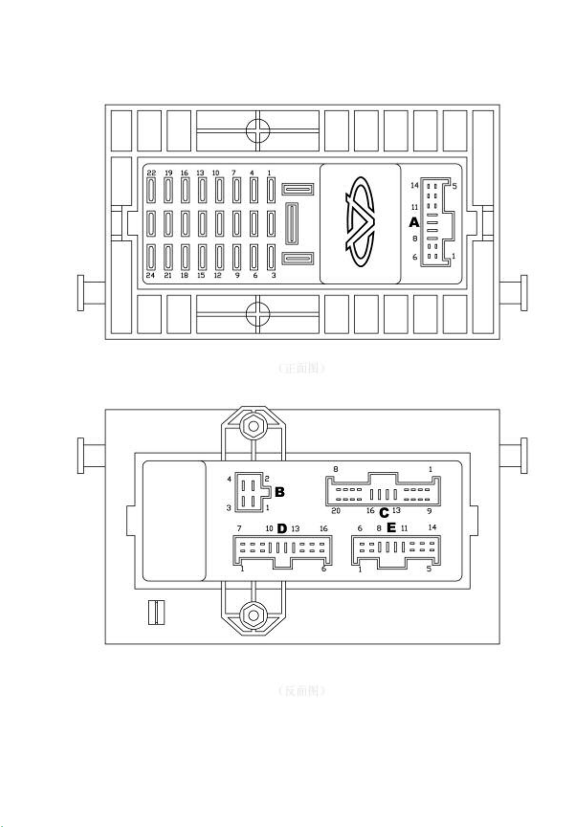
CODE AND FUNCTION DESCRIPTION OF THE INSERTING PART
AND CONTACT IN THE CENTRAL ELECTRICAL BOX
Code of
inserting part
A
01. Sunroof, Taximeter (+15)
02. A/C signal input of ECU
03. ——
04. Trunk lamp, radio, taxi mark light
05. ——
06. ——
07. ——
08. ——
09. Rear window preheating switch, rearview mirror defroster
switch
10. ——
11. Light switch, interior illuminator, power supply for ABS
diagnosis (+15)
12. ——
13. Positive grid of power supply for combined instrument (+15)
14. Brake switch
Function of contact of inserting part Circuit serial No.
——
138
——
247
——
——
——
——
134
——
132
——
114
192
01. ——
B
C
02. ——
03. ——
04. ——
01. Horn switch
02. Fog lamp relay (Positive)
03. Fog lamp switch
04. Horn relay signal (30)
05. Dual-tone horn
06. Wiper motor (Positive)
07. Instrument panel indicator light, switch illuminator,
adjustable resistor of light switch
08. Back-up lamp switch
09. ——
10. ——
11. ——
12. Fog lamp relay (negative)
13. ——
14. ——
15. Thermo-sensitive switch, A/C high voltage switch
16. Positive grid of power supply for central electrical box (+30)
——
——
——
51
142
219
220
140
141
154
209
83
152
——
——
215
——
——
47
6
Page 27

CODE AND FUNCTION DESCRIPTION OF THE INSERTING PART
AND CONTACT IN THE CENTRAL ELECTRICAL BOX
Code of
inserting part
Function of contact point of inserting part Circuit serial No.
17. ——
C
D
18. Wiper intermittent relay
19. License lamp
20. Mileage meter sensor
01. ——
02. Cigarette lighter
03. Turn signal switch, headlamp regulation switch
04. ——
05. Positive grid of combined instrument (+15)
06. Sunroof, Taximeter (+30)
07. Grounding wire
08. ——
09. Rearview mirror switch, regulation module, shift lever box
(+15)
10. Ignition switch (+15)
11. Central lock controller, window regulator module (+30)
12. Ignition switch, wiper switch (+15)
13. Positive grid of power supply for central electrical box (+30)
14. ——
15. ——
16. ——
——
149
210
81
——
129
175
——
116
——
53
——
272
14
260
8
10
——
——
248
01. ——
02. ——
03. ——
04. A/C compressor electromagnetic clutch
05. ——
E
06. ——
07. ——
08. Positive grid of power supply for central electrical box
(+30).
09. Ignition switch (+15)
10. Light switch
11. ——
12. Horn relay
13. ——
14. ——
——
——
——
137
——
——
——
5
9
207
——
139
——
——
Page 28

Illustration Of This Circuit Diagram Book
Page 29

NOTES ON COMPILATION
1. The circuit code on the main circuit board of the central electrical box
30: No fuse, positive grid is connected directly from the battery;
15: No fuse, the positive grid is connect to the ignition switch;
X: No fuse, the positive grid is connect to the ignition switch, and cut off in the starting process.
31: Dummy ground wire, this wire maybe exist or not.
Example: 30(E8) indicates that the positive grid wire of No.30 in the central electrical box is directly output
from the battery and connected to the 8# pin of plug base E in the central electrical box, other symbols such as
30(C16), 15(D10), X(D12)…can be interpreted in the same way.
2. The segmentation of the main circuit board in the central electrical box
This segmentation of the main electrical circuit board includes fuses, relays and connectors.
3. Indicating the extension of the wire or circuit
The circumstances that the wire or circuit been extended are as follows:
——Located at right of the circuit diagram on previous page
——Located at left of the circuit diagram on next page
4. Symbol of the contact point (pin) on the main circuit board of central electrical box
Can be used as “help” in referring to the circuit diagram of main circuit board, example: E/8
indicates the 8thpin of the plug base E in the central electrical box.
5. Color of the wire and cross sectional area of the wire in square millimeters (color of the
wire may not match with the actual item, so the color indicated is only used for reference)
6. Symbol of connector
This symbol is usually marked on the component itself.
7. Name of the part or component (Description can be found at the bottom left in every page of
the electrical circuit diagram).
8. Number label for the extension of circuit or wire
The number in the square box indicates the corresponding circuit serial number with the extension
of the wire in the circuit.
9. Internal wire
For the purpose of searching internal circuit of the component. The circuit comprised of this wire
maybe exist or not.
10. Grounding point
Indicated by a numerical code enclosed in a circle, its connection points are indicated in every
electrical circuit diagram.
11. Circuit serial number
Used for searching components and connection points of the discontinuous wires.
12. Connection points used in the multi-socket plug base
Given the corresponding terminal number for the socket.
Page 30
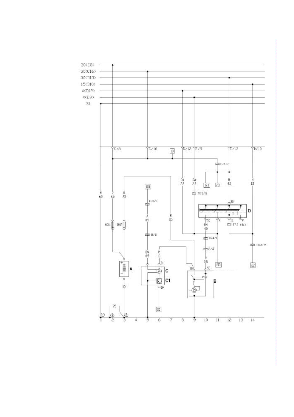
Battery, Ac Generator, Ignition Switch, Starting Motor
Headlamp Switch
/8
Wiper Swit
N=
TQ4
Double
-
socket plug in connector
B=White,
Black,
R=Red,
M=Brown,
V=Green,
A=Blue,
H=Grey,
Z=Viole t,
G=Ye l lo w
A Battery
B Starting Motor
C Ac Generator
C1 Voltage Regulation
D Ignition Switch
ch/2
!Grounding Point, ground bracket beside the central electrical box
" Car body connection point, close to the battery.
# Grounding point of the engine, located at the side of gearbox.
Page 31

MPI System (UAES)
N=
N1
N2
N01
Fuel Pump Relay
Master
Relay
Green
Blue
Brown
Charcoal
Valve
Oxygen
Sensor
B=White,
Black,
R=Red,
M=Brown,
V=Green,
A=Blue,
H=Grey,
Z=Viole t,
G=Ye l lo w
S35 System Fuse
S36 Fuel Pump Fuse
S37 Ecu Fuse
A+ Positive Grid Of Battery
1~4 Cylinder Ignition Coils
2~3 Cylinder Ignition Coils
Q Spark Plug
-N04 Fuel Injector
G Fuel Level Sensor
G6 Fuel Pump
Canister
Solenoid
Page 32

To
Low
Speed Relay
Stepping Motor
Water Sensor
Air Intake Pressure /
Temperature Sensor
Throttle Position
Sen
sor
To High Speed Relay
To
Low
Speed Relay
To High Pressure Switch
To Headlamp Switch
To Air Blower Switch
To Odometer Sensor
Charcoal
Canister
Solenoid Valve
Oxygen
Sensor
Phase Angle
Sensor
Tachogenerator
Knock Sensor
Dia
gnosis Port
To Wate r
Tem pe rat ur e Me ter
Air Intake Manifold Ground
Ground Of Battery Negative Grid
Page 33

Air Conditioner, Operation Mechanism, Cooling System
N=
N
beside of
B=White,
Black,
R=Red,
M=Brown,
V=Green,
A=Blue,
H=Grey,
Z=Viole t,
G=Ye l lo w
A+ Positive grid of battery
E9 Air blower switch
F18 Thermal-sensitive switch
23 Air blower serial regulation resistor
V2 Air blower
V7 Fan motor
J32 Grounding point, ground bracket
the central electrical box
J69 Cooling fan high speed relay
J70 Cooling fan low speed relay
J5 Air blower relay for air conditioner (in the electrical box)
J6 Rear window preheating relay (in the electrical box)
$ Grounding point, in the harness of the i protection sleeve
% Grounding point, ground bracket beside of the central electrical box
Page 34

A/C switch, Internal circulation solenoid valve
N=
N63 Internal circulation solenoid valve
High and low voltage switch
B=White,
Black,
R=Red,
M=Brown,
V=Green,
A=Blue,
H=Grey,
Z=Viole t,
G=Ye l lo w
E35 A/C switch
E36 Internal circulation switch
K84 A/C operation illuminator
F38 External temperature switch
F23 High voltage switch
F73 Low voltage switch
&' Five-socket plug in connector
TK Main circuit grounding wire
Page 35

Oil pressure switch, Coolant temperature sensor,
Hand brake indicator light switch, Odometer sensor
N=
B=White,
Black,
R=Red,
M=Brown,
V=Green,
A=Blue,
H=Grey,
Z=Viole t,
G=Ye l lo w
G2 Coolant temperature sensor
F22 Oil pressure switch (low voltage)
F9 Hand brake switch indicator light
F34 Brake oil level alarm switch
G40 Odometer sensor
()))*ounding point, engine cylinder block
+ Ground connection, in the headlamp harness
TQ1 Ten-socket plug in connector
F34 Ten-socket plug in connector TS2
Page 36

Radio and Six channel loudspeaker
N=
B=White,
Black,
R=Red,
M=Brown,
V=Green,
A=Blue,
H=Grey,
Z=Viole t,
G=Ye l lo w
R Radio
R2 Front left loudspeaker
R3 Front Right loudspeaker
R4 Rear right loudspeaker
R5 Rear left loudspeaker
R6 Front left loudspeaker
R7 Front right loudspeaker
R1 Antenna
T8 8 socket plug in connector
T1 Single-socket plug in connector
Page 37

Instrument Panel And MFA
N=
B=White,
Black,
R=Red,
M=Brown,
V=Green,
A=Blue,
H=Grey,
Z=Viole t,
G=Ye l lo w
F10 Multi-channel converter
F15 Stabilizer
G20 Fuel sensor
G25 Coolant temperature sensor
G30 Rpm sensor
G35 Preset level comparator
J114 Control unit
J119 Multi-function display
K1 Abs alarm light
K2 Left-turn signal lamp
K3 Right turn signal lamp
K4 Generator charging alarm light
K5 Engine self-inspection
indicator light
K6 Hand brake alarm light
Oil pressure alarm light
Engine over-temperature alarm light
Instrument panel illumination light
Instrument panel illumination light
Instrument panel illumination light
Instrument panel illumination light
Low beam lamp,position alarm light
K14 Single socket plug
in connector
K15 Fuel alarm light
Y1 Digital clock
T1 High beam alarm light
Page 38

Front Fog Lamp, Cigarette Lighter, A/C Panel Indicator Light
N=
B=White,
Black,
R=Red,
M=Brown,
V=Green,
A=Blue,
H=Grey,
Z=Viole t,
G=Ye l lo w
A/C panel indictor light
Front right fog lamp
Front left fog lamp
Coolant level switch
Cigarette lighter indicator light
Cigarette lighter
, Grounding point, in the headlamp harness
Page 39

Compressor Magnetic Clutch, Dual-Tone Horn
N=
N25
Z1
Rear win
dow
heater
Rear Window Heating System
B=White,
Black,
R=Red,
M=Brown,
V=Green,
A=Blue,
H=Grey,
Z=Viole t,
G=Ye l lo w
J1 Idle speed accelerating relay (in the electrical box)
J3 Dual-tone horn relay (in the electrical box)
L39 Rear window heating switch illuminator
K10 Rear window heating switch
E15 Rear window heating indicator lamp
Compressor magnetic clutch
H1(2) Dual-tone born
- Grounding connection point, in the harness of dual-tone horn
Page 40

Wiper, Washer, Horn Button
N=
V
5
Wa sh er
B=White,
Black,
R=Red,
M=Brown,
V=Green,
A=Blue,
H=Grey,
Z=Viole t,
G=Ye l lo w
E22 Wiper switch
H Horn button
J31 Intermittent wiper relay
S5 Fuse 15A
V Wiper motor
Page 41

Front Headlamp, Light Relay, Front Position Light
N=
B=White,
Black,
R=Red,
M=Brown,
V=Green,
A=Blue,
H=Grey,
Z=Viole t,
G=Ye l lo w
A+ Positive grid of battery
L1 Left high beam lamp
L2 Left low beam lamp
L3 Right low beam lamp
L4 Right high beam lamp
M1 Right position lamp
M3 Left position lamp
J55 Light relay
S27 Right high beam lamp fuse 10A
S28 Left low beam lamp fuse 10A
S29 Left position lamp fuse 10A
S30 left high beam lamp fuse 10A
S31 Right low beam lamp fuse 10A
S32 Right position lamp fuse 10A
. Grounding point, in the harness of headlamp
Page 42

Turn Signal Lamp Switch, Emergency Alarm Relay
N=
Parking Light Switch
B=White,
Black,
R=Red,
M=Brown,
V=Green,
A=Blue,
H=Grey,
Z=Viole t,
G=Ye l lo w
E2 Tur n signal lamp switch
E3 Emergency alarm light switch
E4 Light changing and turn signal lamp switch
E19 Parking lamp switch
J2 Emergency alarm light relay
K6 Emergency alarm light
S17 Fuse 10A
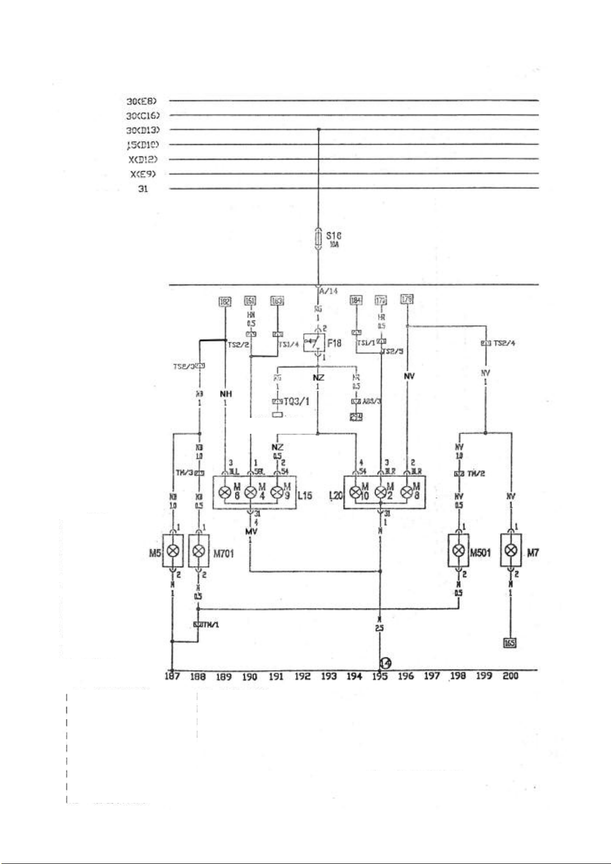
Page 43
Tail Lamp, Stop Lamp, Side Lamp
N=
E
lectronic fuel i
njection
B=White,
Black,
R=Red,
M=Brown,
V=Green,
A=Blue,
H=Grey,
Z=Viole t,
G=Ye l low
F18 Brake lamp switch
L15 Right tail lamp
L20 Left tail lamp
M2 Rear left position lamp
M4 Rear right position lamp
M5 Rear left turn signal lamp
M6 Front left turn signal lamp
M7 Front right turn signal lamp
M8 Rear right turn signal lamp
braking signal
M9 Left brake lamp
M10 Right brake lamp
M501 Right turn signal lamp
M701 Left turn signal lamp
S20 Fuse
S7 Fuse
S8 Fuse
T3 3-socket plug in connector
T1 Single-socket plug in connector
/ Grounded in the rear lamp
Page 44

Light Switch
N=
B=White,
Black,
R=Red,
M=Brown,
V=Green,
A=Blue,
H=Grey,
Z=Viole t,
G=Ye l lo w
E1 Light switch
E20 Panel indicator light/adjustable
resistor for instrument illuminator
L9 Panel indicator light
S3 Fuse 10A
Page 45

Rear Fog Lamp, Backup Lamp
N=
B=White,
Black,
R=Red,
M=Brown,
V=Green,
A=Blue,
H=Grey,
Z=Viole t,
G=Ye l lo w
E23 Front fog lamp switch
J4 Fog lamp relay (in the electrical box)
K17 Rear fog indication lamp
L1 Rear fog lamp
L40 Front and rear fog lamp switch illuminator
S10 Fuse 15A
S14 Fuse 10A
E24 Rear fog lamp switch
T3 Three-socket plug in connector
T3a Three-socket plug in connector
T2 Two-socket plug in connector
T1 Single-socket plug in connector
T1a Single-socket plug in connector
Page 46

Interior front and rear lamp, Trunk lamp, Door switch,
N=
License lamp, Shadow shield light
B=White,
Black,
R=Red,
M=Brown,
V=Green,
A=Blue,
H=Grey,
Z=Viole t,
G=Ye l lo w
F2 Front left door switch
F3 Right front door switch
F5 Luggage boot light switch
F10 Rear right door switch
F11 Rear left door switch
TB Two -socket plug in connector
TD Four-socket plug in connector
TAa Tw o-socket plug in connector, left of luggage boot
W1 License lamp
W3 Trunk lamp
W4 Shadow shield light
W5 Delay on/off interior front ceiling light
X Interior rear ceiling light
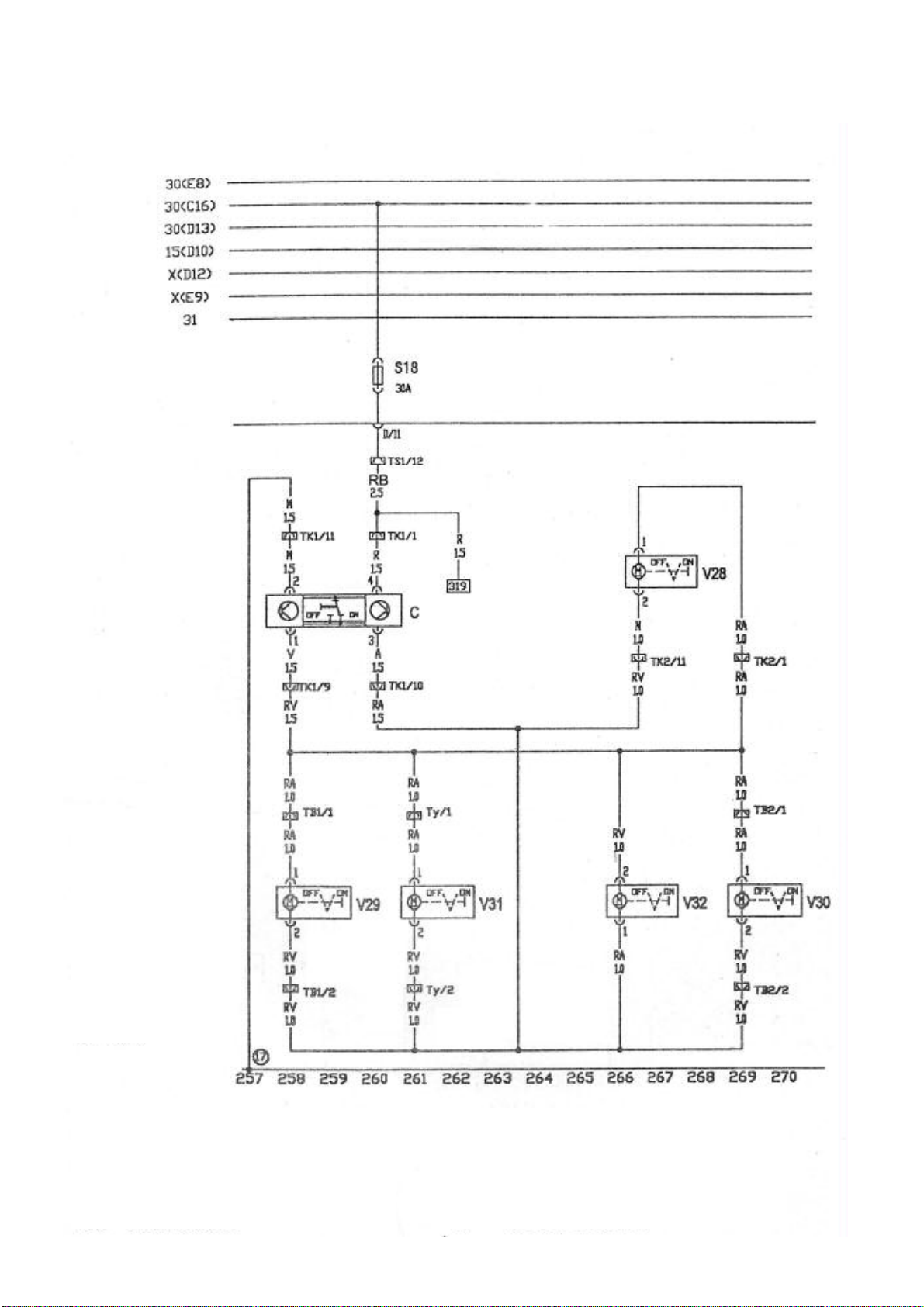
Page 47
Central Door Lock
N=
B=White,
Black,
R=Red,
M=Brown,
V=Green,
A=Blue,
H=Grey,
Z=Viole t,
G=Ye l lo w
C Central lock controller (in the front left door)
V28 Front right door lock control motor
V29 Rear left door lock control motor
V30 Fuel tank lid control motor
V31 Trunk lock control motor
V32 Rear right door lock control motor
TB1 Four-socket plug in connector (left column B)
TB2 Four-socket plug in connector (right column B)
TK1 12-socket plug in connector (left column A)
TK2 12-socket plug in connector (right column A)
Ty Tw o-socket plug in connector (left column C)
0 Grounding point beside of the central electrical box
Page 48

Electrical Rearview Mirror
N=
B=White,
Black,
R=Red,
M=Brown,
V=Green,
A=Blue,
H=Grey,
Z=Viole t,
G=Ye l lo w
F77 Rearview mirror switch
X1 Left adjustment
X2 Down regulation
Y1 Up regulation
Y2 Right regulation
V17 Left rearview mirror control motor
V25 Right rearview mirror control motor
Z4 Left rearview mirror defroster
Z5 Right rearview mirror defroster
TK1 12-socket plug in connector (left column A)
TK2 12-socket plug in connector (right column A)
TZ 2-socket plug in connector
(at the side of central electrical box)
Page 49

B=White,
N=
N55 ABS solenoid valve
Black,
R=Red,
M=Brown,
V=Green,
A=Blue,
H=Grey,
Z=Viole t,
G=Ye l lo w
J104 ABS controller
A Battery
VG4 ABS hydraulic pump
G44 Rear right wheel RPM sensor
G45 Front right wheel RPM sensor
G46 Rear left wheel RPM sensor
G47 Front left wheel RPM sensor
S33 Power supply fuse of ABS solenoid valve
S34 Power supply fuse of ABS hydraulic pump
TK Diagnostic port
1 Grounding point, ground bracket at the side of central electrical box
Page 50

Control Unit Of Electrical Window Regulator
B=White,
N=
Black,
R=Red,
M=Brown,
V=Green,
A=Blue,
H=Grey,
Z=Viole t,
G=Ye l lo w
G Win do w regulator module
E40 Front left window regulator switch
E81 Front right window regulator motor
V14 Motor of front right window regulator
V15 Motor of front left window regulator
2 At the side of central electrical box
TK1 12-socket plug in connector (right column b)
TK2 12-socket plug in connector (left column b)
Page 51

Control Switch Of Electrical Window Regulator
N=
B=White,
Black,
R=Red,
M=Brown,
V=Green,
A=Blue,
H=Grey,
Z=Viole t,
G=Ye l lo w
E39 Rear window regulator lock switch
E52 Rear left door window regulator switch
E54 Rear right door window regulator switch
E53 Rear right door window regulator switch
E55 Rear left door window regulator switch
V26 Rear left door window regulator motor
V27 Rear right door window regulator motor
TA1 4 -socket plug in connector (right column b)
TA2 4 -socket plug in connector (left column b)
Page 52
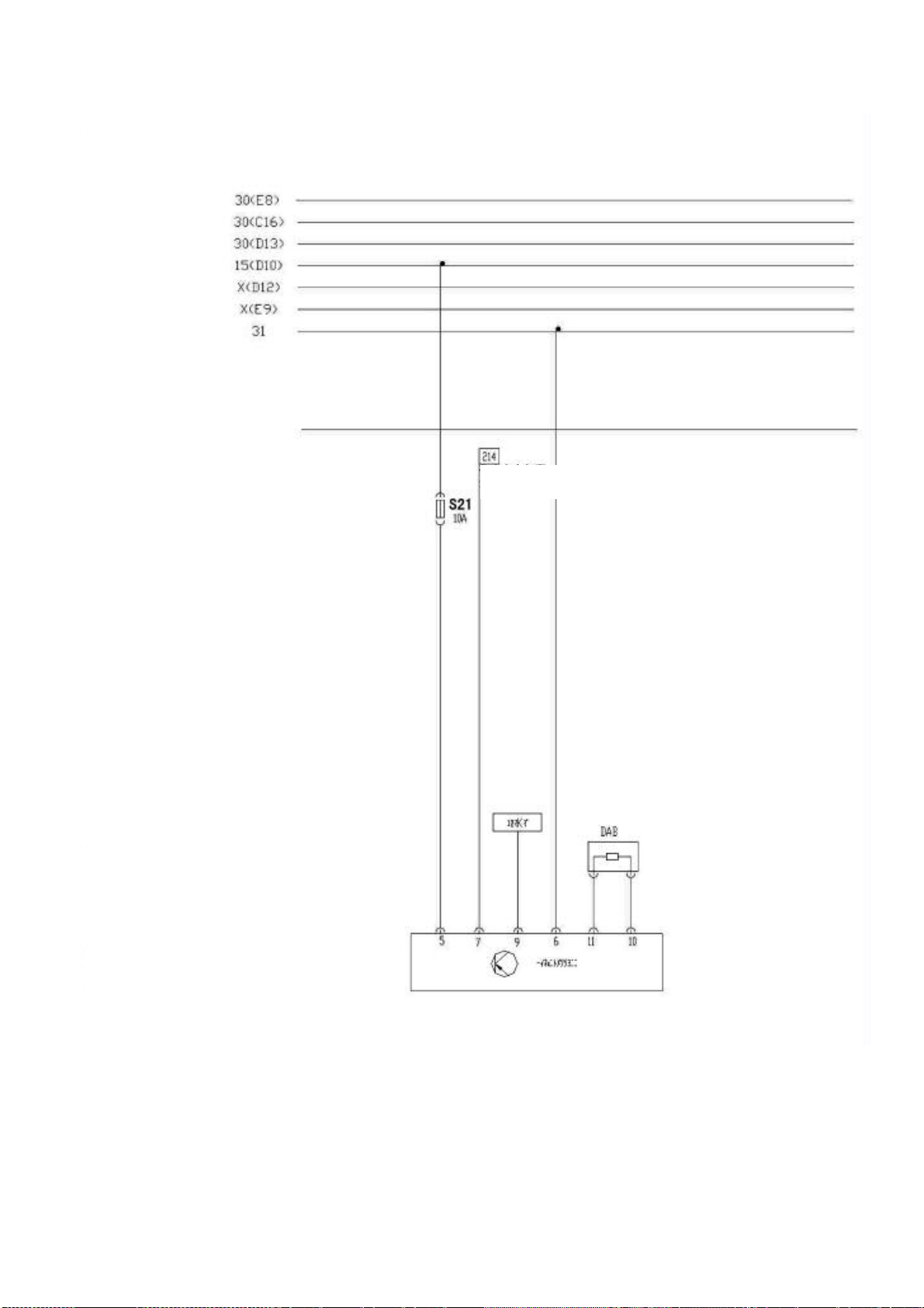
Air Bag Control Module
N=
Malfunction alarm light
Instrument air bag
B=White,
Black,
R=Red,
M=Brown,
V=Green,
A=Blue,
H=Grey,
Z=Viole t,
G=Ye l lo w
Page 53

AXLE AND SUSPENSION SYSTEM
ALIGNMENT OF THE WHEEL … … … … … … …… … … … … … … … …M-2
BASIC INSPECTION BEFORE THE ALIGNMENT……………………… … …M-2
USUAL TROUBLE OF THE TIRE… … … … … …… … …… … … …… … …M-5
ALIGNMENT OF THE REAR WHEEL … … … … … … … ……… … … … … M-9
ALIGNMENT OF THE FRONT WHEEL… … … … … … ………… … ……M-10
FRONT SUSPENSION… … … … … … … … … …… … … … … … …… …M-13
REMOVAL AND INSTALLATION OF THE FRONT SUSPENSION………… …M-13
OVERHAUL OF THE FRONT SUSPENSION… … … … … … … ……… … …M-15
REMOVAL AND INSTALLATION OF THE FRONT WHEEL BEARING … … M-19
REAR SUSPENSION AND REAR AXLE… … … … … … … …… … …… … …M-22
REMOVAL / INSTALLATION OF THE REAR AXLE ASSY …… … … …… …M-22
REMOVAL / INSTALLATION OF THE REAR SHOCK ABSORBER ASSY … M-25
OVERHAUL OF THE FRONT AND REAR AXLE… … … … … … …… ……M-28
M-1
PDF created with pdfFactory Pro trial version www.pdffactory.com
Page 54

AXLE AND SUSPENSION SYSTEM
ALIGNMENT OF THE WHEEL
It is easy to understand that the theory of the four wheels alignment related to the definitions
and the functions of various angles. However, the corresponding theory can hardly be applied
to the four wheels alignment tester and chassis maintenance due to the chassis structure of the
vehicle body, which all the angles of the four wheels alignment bear on the mechanical
structure of the chassis. For examples:
--The camber will be changed as the toe-in varied. The wheels will be turned while
adjusting the toe-in, which results the camber changing. The larger the caster is, the
more the camber changed.
--The wheel setback will be changed as the caster adjusted. When the caster increases or
decreases, the upper fulcrum of the steering shaft can move forwards or backwards and
the lowest fulcrum of the steering shaft (tire) is also movable. The front wheel moves
forwards or backwards along with the caster increasing or decreasing so that the axle
setback will be altered. The turn plate must have the function of sliding forwards and
backwards in order to make the front wheel move forwards and backwards freely.
--The toe-in will be changed as the camber varied and vice versa. Various suspension
structures have different ways to adjust the camber. If the upper or lower fulcrum is
moved left or right, not only the camber but also the toe-in will be changed. As a result,
even if the camber is properly adjusted, the stable driving status cannot be achieved
because of the toe-in changing. Therefore, after eliminating of malfunction, another one
will appear.
--Changing the toe-in of the rear wheel influences that of each front wheels. The toe-in of
the rear wheel determines the thrust angle of the rear wheel. The method of thrust line
positioning is adopted to determine the toe-in of the front wheel in all the advanced four
wheels alignment testers.
Precaution: The front wheel must be adjusted first and then the rear wheel when
processing the four wheels alignment. The sequence of the rear wheel adjustment is the
camber first, the toe-in second and so on. And the sequence of the front wheel
adjustment is the caster first, the camber second, the toe-in third and so on.
BASIC INSPECTION BEFORE THE ALIGNMENT
Check the tire pressure, tire No. and rim No.
----Check the tire pressure and adjust it to the specified pressure
Tire inflation pressure kPa
Item Front wheel
No-load/half-load
200 220 350 420
Rear wheel Spare wheel Mini spare wheel
Full-load 210 260 420 420
M-2
PDF created with pdfFactory Pro trial version www.pdffactory.com
Page 55

----Rim and Tire
A15LHD wheel No.
Tire No. Rim No.
185/60 R14×82H 6J×14
Note:
The above tire-rim combination is suitable for the steel or aluminum alloy rim. Please
do not use rims and tires of other models which may lead to improper consequence.
Preaution: Be sure to consult the relevant instruction if non-standard tires or rims (such
as light weight alloy rims or wheels of winter tire)should be installed.
Positioning of the tire
Different working conditions between the front wheel and the rear wheel lead to the different
wear status, which depends mainly on the road condition, the driving custom and so on. The
front wheel wears faster than the rear one does. In order to prevent the tires from wearing in
different degrees and to prolong the service life of the tires, it is necessary to check and rotate
the tires, adjust the tire pressure, and examine the tightening degree of the wheel bolt at
interval of 5000km.
------ Utilization of the cold-resistant tire
If using the cold-resistant tire, all the four tires must be replaced at same time. Please do not
excess the top speed and must accord to the tire pressure limited by the tire manufacturer.
Precaution: Using the cold-resistant tire may affect the safety and the maneuverability
of the vehicle. Standard tires in same size and No. should be utilized. Do not use the
cold-resistant tire as long as the road condition is available.
------Snow chain
M-3
PDF created with pdfFactory Pro trial version www.pdffactory.com
Page 56

Adjusting the snow chain of the tire should accord to the type of the road condition.
Inspection must be applied before install the snow chain. Please refer to the instruction of the
snow chain manufacturer when install the snow chain on the tire. Please remove the wheel
house before install the snow chain which may score the wheel house. Install the snow chain
firmly on the front tire. It is not recommended to fix the snow chain on the rear wheel. The
snow chain should be retightened after 0.5~1.0km driving with it.
Precaution: Using the snow chain may affect the vehicle maneuverability, so the vehicle
speed should not excess 50km/h (30mph) or the speed limited by the snow chain
manufacturer(less than 50km/h). Please stop the car and tighten the snow chain
immediately when hearing collision between the snow chain and the vehicle body or the
chassis when using the snow chain. Abrupt turning, concussion and passing the
chuckhole, the vehicle locking and braking should be avoided. The instruction of the
snow chain manufacturer should be also complied. Improper utilization of the snow
chain will cause interference between the snow chain and the vehicle body.
Installation of the tire
----Make sure that the opening of the valve is slippery and no burrs before installing the tire
valve. Then apply glycerol onto the rubber surface of the tire valve or dip it briefly in the
glycerol. Pull or press the locating ring of the tire valve with special purpose tool at the
force of 200-400N in order to make it through the hole on the wheel, which means the
installation is finished. (Suds are permitted to replace the glycerol.)
----Wipe glycerol or suds round the bead before installing the tire, and please note at the
same time:
When there is a light point mark on the rim, please aim the uniformity test mark at the point.
When there is no light point mark on the rim, please aim the dynamic balance test mark at
the position of the tire valve.
When there is no light point mark on the rim and no dynamic balance test mark but the static
balance test mark on the tire, please aim the tire valve at the static balance test mark.
The instructions for the uniformity, dynamic balance and static balance test mark of the tire
should be offered by the production department or the supplier in written form.
----Inflate the tires according to the specified pressure strictly. Please do not excess 10% of
the rated pressure during inflating. The spare tire assy is assembled at the rated pressure
of 3.5atm and is separately stored with the four tires installed on the vehicle. Please check
and adjust the tire pressure before the four wheel alignment: front wheel 2.0±0.2atm,
rear wheel 2.1±0.2atm.
----Screw the valve cap after inflating the tire and undergo the dynamic balance test. Set the
proper weight balance block onto the inside and outside brims of the rim as required. The
M-4
PDF created with pdfFactory Pro trial version www.pdffactory.com
Page 57

final assy imbalance is expected to be less than 100g·cm, approximately equal to a 5g
balance block on the inside and outside brims of the rim.
Precaution: No more than one balance block with 70g weight at most is allowed to
set on each side of a wheel. Avoid over hitting on the balance block. If that happened,
replace it immediately. Do not reuse the replaced balance block.
----During installing the wheel and the tire assy, pre-screw the wheel bolt on the rim by hand
first, and then tighten the screws with the special purpose tools under the way of diagonal
method, (the tightening torque is 100±10N·m). No impact wrench is allowed in order to
avoid screwing too tight or loose. Do not use lubricating grease while installing the wheel
bolt. (The wheel bolt should be tightened to maintain the tightening torque after the initial
100km driving since the new installation of the wheel and tire assy. The check of the
tightening torque of the wheel bolt is one of the daily service items.)
----Decussating method is adopted to tighten the set nut. The tightening degrees should be
similar so that the wheels can turn freely. The wheel should stand on the ground during
the last tightening.
----Install the trim cover or place it as required. Clip trim cover should be installed into
through beating by hand or prying by rubber tools.
USUAL TROUBLES OF THE TIRE
Proper utilization of the tire
The tire is an important part of the wheel assy. Please pay attention to the following items
while using:
------The tire of the same manufacturer and the same No. should be used on the same vehicle.
------Do not install tires out of the specified types
------Make all the tires wear evenly. In order to remedy and lighten the uneven wear, besides
periodic checking and correcting the parameters of the wheel alignment, the rotation
should be also applied. The specific rotation way depends on the practical wearing status.
It is recommended to adopt the tire rotation at interval of 5000~8000km
Usual troubles of tires and trouble diagnosis
------Wear on shoulder of tire
The wear on shoulder of tire means the brim with burrs forming of the tire wears are more
badly than other parts. The theoretical reason for the wear on shoulder of tire is that the tire
rolls at the limit lateral runout angle.
Main reason: Frequently steering at high speed, improper adjusting the toe-in and the camber,
or often driving on the vaulted or zigzag road.
M-5
PDF created with pdfFactory Pro trial version www.pdffactory.com
Page 58

Maintenance: Adjusting the positioning angle of the front wheel
------Wear on center of tire
The wear on center of tire means the abnormal wear on the center surface of the tire. The
theoretical reason for this kind of wear is that the diameter elongation at the center of the tire
surface is larger than that on the shoulder of the tire.
Main reason: Overhigh tire pressure
Maintenance: Readjusting the tire pressure to make it within the range of the specified value.
------Serrated wear
The serrated wear means the wear on the surface of the tire strip in ladder shape. The
theoretical reason for this kind of wear is the uneven deformation of the tread pattern of the
tire contact patch.
Main reason: The toe-in and the camber are not conformed to the specified value
Maintenance: Adjusting the toe-in and the camber to make it within the specified value.
Checking the tire pressure is within the specified range.
------Initial severe wear somewhere on the tire
The initial severe wear is the severe wear on the tread pattern of tire contact patch due to the
wheel locking while emergent braking.
Main reason: Vehicle speed while emergent braking, road conditions, wheel load and the
braking intensity
Maintenance: Avoiding emergent braking and taking precautionary measure as early as
possible
------Nick and crack on the sidewall of tire
The main reason is the sharp things on the road or the little stones, nails and metal flakes
embedded into the tread slot.
------Initial wear on half round of the tire or wear in different places of the shoulders on
both sides
The main reason is the gyration part is in unbalanced state, or the tire and wheel are eccentric,
or the bearing is worn or loose and so on. The eccentricity or bend of the rim or the steering
knuckle may also cause the wear.
Troubleshooting Guide
Trouble Possible causes Solutions
Serious wear of tire
Tire noise Improper tire pressure Adjust
PDF created with pdfFactory Pro trial version www.pdffactory.com
Improper tire pressure Adjust
M-6
Page 59

Degradation of tire Replace
Road noise or
vehicle vibration
Up-and-down
shaking of steering
wheel
Circular vibration of
steering wheel
Insufficient tire pressure
Unbalance of tire
Deformation of rim or tire
Uneven wear of tire
Overbeating of tire and rim
Looseness of wheel nut
Unbalance of tire
Breach or wear of engine bearing
pad
Breach or wear of transmission
bracket rubber
Overbeating of tire and rim
Looseness of wheel bolt
Unbalance of tire
Uneven wear of tire
Insufficient tire pressure
Damage or wear of front wheel
bearing
Malfunction of steering system
Malfunction of suspension system
Adjust
Adjust
Repair or
Replace
--
Replace
Lock
Adjust
Replace
Replace
Replace
Lock
Adjust
--
Adjust
Replace
--
--
Improper tire pressure
Serious or uneven wear of tire
One side deflection
of steering wheel
Unstable running
PDF created with pdfFactory Pro trial version www.pdffactory.com
Malfunction of steering system
Malfunction of braking system
Malfunction of suspension system
Uneven tire pressure of both sides
Deformation of rim or tire
Looseness of wheel bolt
Malfunction of steering system
M-7
Adjust
--
--
--
--
Adjust
Repair or
Replace
Lock
Page 60

Malfunction of suspension system --
--
One side deflection
of braking
Heavily steering of
steering wheel
Improper
returnability of
steering wheel
Check whether the connection of the transmission rod of steering system is loose,
deformed, etc.
Check the status of the ball joint and the rubber bush of front and rear suspension
Check whether the shock absorber works normally
Uneven tire pressure of both sides
Malfunction of braking system
Insufficient tire pressure
Malfunction of steering system
Malfunction of suspension system
Insufficient tire pressure
Malfunction of steering system
Malfunction of suspension system
Adjust
--
Adjust
--
--
Adjust
--
--
------Check whether the shock absorber leaks grease
------Check whether the bush wears out
------Check whether the shock absorber is improper through shaking the vehicle body up and
down by pressing the foreside and the tail of the vehicle
Pre-check before wheel alignment
------Check the status of the tire inflation. Adjust to the recommended pressure if necessary.
------Check the clearance of the front wheel bearing. Adjust it if necessary.
------Check the flop of the vehicle and the tire.
------Check whether the ball joint and the steering linkage are too loose.
------Check the shock absorber by shaking the vehicle.
Note:
The vehicle must be on the level ground with no-load.
No-load: Full gasoline in the oil reservoir, engine coolant and the oil filled at the specified
level; the spare tire, jack and tools in the pointed position.
M-8
PDF created with pdfFactory Pro trial version www.pdffactory.com
Page 61
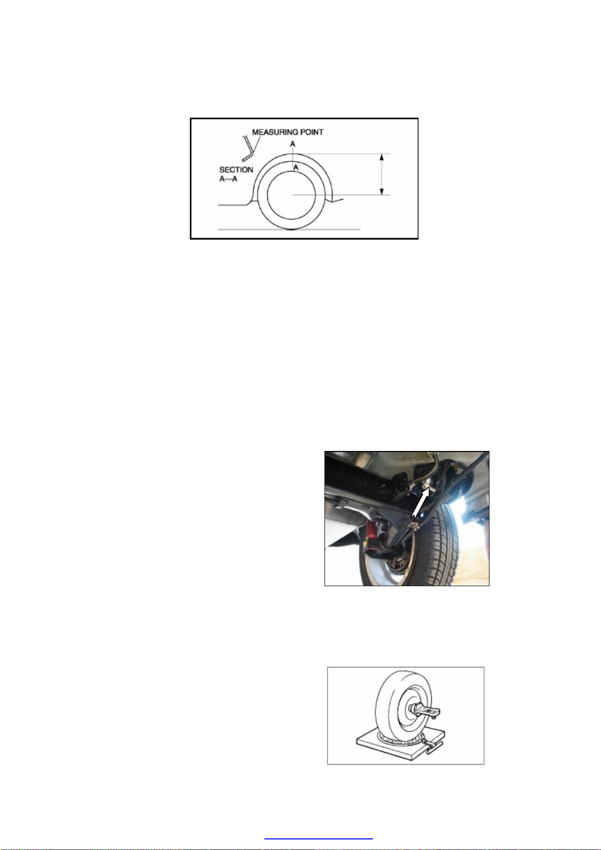
------Measure the height from the wheel center to the mudguard edge. The measured
rear wheel should be adjusted
difference from left and right should be not more than 10mm.
ALIGNMENT OF THE REAR WHEEL
It is recommended to utilize the four-wheel alignment tester with thrust line positioning
method on this type of chassis.
Note: thrust line positioning is defined as adjusting the front wheel toe-in based on the
rear wheel thrust line.
With the thrust line positioning, the adjustment of the rear wheel toe-in will influence the
single front wheel toe-in, so during four-wheel alignment, the
before the front wheel alignment.
Measure the vehicle height
------Rear measure point
From ground to the center of the joint bolt of
the rear axle and the body (as the arrow
shows)
Precaution: Check whether the height from
left and right are same before processing
the wheel alignment
------If there is a difference of the heights from
left and right, that means there are
damaged or deformed components of the
front and rear suspension.
Install the wheel alignment tester on wheel
------Please refer to the specific instruction of
manufacturer for the wheel alignment
tester.
M-9
PDF created with pdfFactory Pro trial version www.pdffactory.com
Page 62

Check the caster
Inspection angle Value
Rear wheel caster -1°30′±10′
Note: The rear wheel caster cannot be adjusted. If there is abnormal wear on the tire of
the rear wheel, so check whether there are worn or deformed parts on the rear
suspension
Check the rear wheel toe-in
Car No. Chery A15LHD
Rear wheel toe-in 20′±10′
Note: The rear wheel toe-in out of standard range may lead to wear on shoulder of
tire on both sides. If the differences of the rear wheel toe-in both rear wheel are too
much, the vehicle running direction may be affected. Therefore the rear wheel toe-in
is a vital parameter of the alignment angles.
ALIGNMENT OF THE FRONT WHEEL
------Install the wheel alignment tester on the wheel
Please refer to the specific instruction of manufacturer.
------Check and adjust the wheel camber and the kingpin caster of the front wheel
according to the standard
Angle Value
Front wheel camber -30′±20′
Kingpin caster 1°30′±30′
Note: Adjust the caster before the camber
Kingpin caster
There is no need to adjust the kingpin caster for it is assured by the structure of design
M-10
PDF created with pdfFactory Pro trial version www.pdffactory.com
Page 63

Influence of caster
The main function of the caster is to keep the vehicle running straight forward. If the caster is
positive, the inside of the vehicle descends and the chassis ascends which increase the
steering knuckle load when the front wheel turns. If the casters of two wheels are same, the
vehicle will return forward after turning. Increasing the positive caster angle will enhance
stability of the steering wheel while the steering force will be increased at the same time.
Decreasing the positive caster may reduce stability of the steering wheel but lightens the
steering force.
The angle of the caster could not make the wear on tire. It is used to stabilize the steering
direction and to return automatically after steering. If the vehicle is equipped with a
traditional manual steering wheel, the caster is small or even tends to negative, which makes
the steering easy. If the vehicle is equipped with a power steering wheel, the caster is usually
set to be large positive in order to offer the driver a better feeling. Increasing the positive
caster will increase the steering force but enhances the stability of straight running.
Adjust the camber
Under normal condition, there is no need to
adjust the camber after assembling the
independent suspension and the wheel
steering knuckle. Use the joint bolt of the
independent suspension and the steering
knuckle to calibrate the wheel camber if the
camber is out of the tolerance range for other
reasons.
----Check (visual inspection) whether there
are damaged parts in the steering system
and replace the damaged ones before the
calibration.
----If the front wheel camber is out of the
tolerance, loosen the joint bolt of the
front shock absorber and the steering
knuckle and move the wheel to calibrate.
----For the further calibration, use the
substitute bolt to adjust the wheel
camber. Replace the M12 bolt with the
M11 bolt. The camber is allowed to be
adjusted within about ±1° shown as the
illustration
M-11
PDF created with pdfFactory Pro trial version www.pdffactory.com
Page 64

----The connection between the lower
control arm of the suspension and the
steering knuckle is clearance fit.
Loosen the joint bolt, move the wheel
and adjust the camber.
Check the front wheel toe-in
Toe-in (general)
Car No. Chery A15LHD
Front wheel toe-in 0′±10′
Tightening torque of toe-in: 55±5N•m.
Adjust the toe-in
Optical tester or mechanical toe-in adjuster can be used to adjust the toe-in.
----According to the tester’s requirement, make the wheel alignment well before the
adjustment;
----Loosen the lock nut and the elastic cover snap ring of the right steering tie rod, and
then screw the toe-in adjusting rod till the length of the rod reaches the specified
value.
----Tighten the lock nut and reinstall the elastic cover snap ring. Check whether the lock
nut is tightened enough and cover is in the correct position.
----After adjusting the front wheel toe-in, check whether the steering wheel is level. If not,
loosen the lock nut of steering wheel, and then adjust to the level position. The
tightening torque of the steering wheel lock nut is 55±5N•m as required.
M-12
PDF created with pdfFactory Pro trial version www.pdffactory.com
Page 65

FRONT SUSPENSION
The functions of axle and suspension system include receiving the torque generated by
engine and passed via transmission system; producing the traction force between the road
surface and the vehicle body through the adhesive force between the driving wheel and the
ground in order to keep the whole vehicle steering normally; passing and bearing the
counterforce on the wheel from different directions and relieving the impact and shake from
the road to the vehicle body in order to ensure the stability and maneuverability of the whole
vehicle. The front suspension is composed of the sub-frame, lateral stabilizer bar, control arm
and etc.
REMOVAL AND INSTALLATION OF THE FRONT SUSPENSION
----Loosen the opening of the joint bracket of
the front shock absorber assy and clip it
to the bolt of the steering knuckle
arm(tightening the lock nut to 80N•m),
(shown as the picture)
----Remove the joint bolt of the control arm
assy and the front steering knuckle with
braker, and then release the front control
arm assy.
Inspection of the control arm: check the
situations of the damage crack and bend.
----Loosen the four bolts amounted on the
sub-frame of the steering gear with tie rod
assy (the specified tightening torque is
30N•m). (shown as the picture)
M-13
PDF created with pdfFactory Pro trial version www.pdffactory.com
Page 66

----Suspend the engine and transmission assy,
loosen the bolts at the two supporting
points from the engine and transmission
to the sub-frame.
Caution: The removal process is extremely
dangerous which could cause serious
damage or even death. Please make sure the
power assy is well fixed.
----Loosen the lock nut of the left-right
steering tie rod and the steering knuckle
arm, knock from one side to pry the ball
joint out of the steering knuckle arm (The
tightening torque is specified as 35±3
N·m).
----Stand the front sub-frame by jack and
loosen the four long-short bolts of the left
-right sub-frame with the cross beam.
(The tightening torque is specified as
130±10 N·m).
Caution: The removal of the cross beam is
extremely dangerous. The drop of cross
beam components could cause serious
damage or even death. Please make sure
that the jack has supported fully the cross
beam components before the removal.
M-14
PDF created with pdfFactory Pro trial version www.pdffactory.com
Page 67

OVERHAUL OF THE FRONT SUSPENSION
front shock absorber assy
Installation of the front axle
Cherry adopts the divided steering drive axle as
the front axle. The suspension is the model of
shock absorber (also called MacPherson)
independent suspension. The front suspension
of A15RHD model has the functions of both
driving and steering. The top of the suspension
is connected with the vehicle body while the
bottom with the steering knuckle. The wheel
camber is adjusted through the joint bolt of the
suspension the steering knuckle. The sub-frame
enhances the stability and comfortability of the
vehicle through the connection of the control
arm ball pin and the hinge by adopting the
elastic components.
Overhaul of the front suspension
----When overhaul the front suspension, please
do not weld or remodel the support and
guide devices of the front suspension.
----Use the special purpose tools to remove the
joint bolts or nuts. Make sure the
tightening torque fits the specified value.
Illustration. The installation of the
front strut assy
1-
2-front dust cover
3-front bumper block4-slotted nut
40N•m
5-bearing and vibration isolator assy
6-front spring top tray
7-washer 8-front coil spring
----When install the sub-frame to the vehicle
body, the sequence of tightening the joint
bolts is the rear left bolt, the rear right
bolt, the front left bolt and the front right
bolt last.
----Check the position of steering wheel and
measure the data of front wheel
alignment after installation.
Overhaul of front shock absorber assy
----Structure of the front shock absorber
(shown as the illustration)
M-15
PDF created with pdfFactory Pro trial version www.pdffactory.com
Page 68

Removal of the front shock absorber assy
Precaution: Before the procedure below, the
careless pull may lead the disconnection of
the harness if the ABS vehicle speed sensor is
not removed first. Therefore, before the
following procedure, remove the ABS vehicle
speed sensor (the axle side) first and fix it in
a proper position in order to keep the sensor
untouched during the vehicle maintaining.
----Remove the wheel. Then loosen the joint
bolt of the propeller shaft and the brake
disc.
----Use the special socket wrench to remove the
joint bolt of the shock absorber strut and
the steering knuckle arm. (shown as the
illustration)
----Use special purpose tools to remove and
install the shock absorber coil spring.
(shown as the illustration) During the
removal, push down the vibration isolator
assy of the coil spring by puller first,
compress the coil spring, and then loosen
the piston rod nut to release the tension of
the coil spring.
Caution: The removal of the piston rod nut is
extremely dangerous, because the shock
absorber and the spring will burst out under
tremendous pressure which could cause
injury or even death. Please make sure the
shock absorber is fixed properly before the
removal of the piston rod nut.
Installation of the front shock absorber
(refer to the installation illustration of the
front strut assy)
Illustration. The installation of front
strut assy
1-Front shock absorber assy
2-Front dust cover
3-Front bumper block
4-Slotted nut 40N•m
5-Bearing and vibration isolator assy
6-Front spring top tray
7-Washer 8-Front coil spring
----Assemble the front cover dust 2 with the
front bumper block 3, and then cover them
onto the piston rod of the front shock
absorber 1.
M-16
PDF created with pdfFactory Pro trial version www.pdffactory.com
Page 69

----Set on the front coil spring 8 and compress it
less than 200~220mm.
----Amount the washer 7, the front spring top
tray 6, the bearing and vibration isolator
assy 5 in sequence, and tighten the slotted
nut 4 to the specified torque (40N•m), then
loosen the compressing tools on the coil
spring.
Precaution: Please note that the two ends of the
front coil spring should reach the corresponding
locating positions of the spring trays.
Inspection of the shock absorber: The
methods for checking the shock absorber are
as following:
----Method of hand pressing the vehicle body.
Shake the vehicle body for times on the
side of the shock absorber which required
to be checked and feel whether it is
available. After the pressing, the vehicle
will shake 2-3 times and then stop, which
means the shock absorber works well.
----Method of observation. The shock absorber
should not leak oil at outside appearance.
A little oil stain is normal. If there is
serious leakage, the shock absorber should
be replaced.
----Method of touch. After long time running,
touch the exterior of the shock absorber to
check whether it is hot. If not hot, the
shock absorber is in trouble.
----Method of pulling and pressing. Place the
piston rod of the shock absorber upwards,
then pull and press it by hand for times and
check:
a whether there is a force during pulling and
pressing which means the force is large
while pulling up and small while pressing
down.
b whether there is idle stoke during pulling and
M-17
PDF created with pdfFactory Pro trial version www.pdffactory.com
Page 70

pressing which means there is a force in
lower part and not abruptly in upper part
while pulling; there is a force in lower part
and not in upper part while pressing.
c whether the shock absorber is locked and
unable to pull.
d whether the piston rod of shock absorber is
severely loose.
Note: The above phenomenons indicate the
failures of the shock absorber.
Deal with the front shock absorber
Caution:
Whenever drilling on the shock absorber,
please wear the goggles. The air pressure
in the shock absorber could probably blow
the metal flakes into eyes or face.
----Clamp the shock absorber on flat ground or
point the piston downwards to the clamped
absorber.
----Drill a hole of 2-3mm diameter at a distance
of 20-30mm to the bottom of the tube in
order to emit the air of the tube.
----Turn the shock absorber to make the hole
downwards.
----Move the piston rod up and down for times
to concentrate the oil, then cut the tube at
the end.
----Process the waste oil according to the waste
disposal method.
Note:
The shock absorber air is nitrogen.
The shock absorber oil is mineral oil.
M-18
PDF created with pdfFactory Pro trial version www.pdffactory.com
Page 71

REMOVAL AND INSTALLATION OF THE FRONT WHEEL BEARING
Removal:
----Remove the front brake disc and the dust
plate, and then extrude the hub.
----Remove the spring retainer of both sides and
extrude the wheel bearing. (shown as the
illustration)
----Pull out the bearing inner race. Use the puller
with hoop to pull the wheel bearing inner
race out of the wheel hub. (shown as the
illustration)
Inspection:
----After all the components are disassembled,
please clean and check them, and replace
them with new ones if necessary.
----If the working surface of the brake disc wears
severely beyond the specified value (wearing
limit: 10.0mm), please replace it with a new
one.
Caution: Do not exceed the wearing limit.
----If the dust plate is severely deformed, please
replace it with a new one.
----If the hub spline wears severely and looses,
please replace it with a new one.
----If the spring retainer is not available, please
replace it with a new one.
----If the wheel bearing is damaged, please
replace it with a new one.
Installation and adjustment
----Set the outer spring retainer first, apply the
lubricating grease onto the wheel bearing
holder and then press the bearing down to the
limit position, as shown in the illustration,
and fix the inner spring retainer last.
----Adjust the split positions of the inner and
outer spring retainer so as to make their
difference 180°. Then rotate the bearing inner
M-19
PDF created with pdfFactory Pro trial version www.pdffactory.com
Page 72
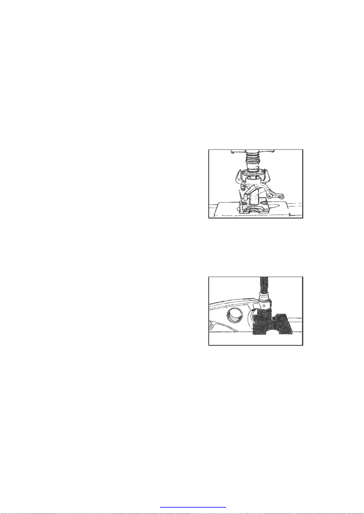
race and observe whether it runs normally.
----Apply the lubricating grease on the hub spline
and the bearing neck, and then press the hub
into the bearing.
----Tighten three M6 bolts to fix the dust plate
with the tightening torque of 10N·m.
----Use the fuzz-free cloth to clean the working
surface of the brake disc. If there is oil stain
on the surface, clean it with ethanol. And
then install the brake disc.
----Rotate the brake disc and observe whether
there is lock or abnormal noise.
OVERHAUL OF THE LOWER CONTROL
ARM
Check the status of damage, crack and bend of
the control arm.
Replace the ball joint and the rubber cover of the
lower control arm if they loose or wear.
Replace the front housing of the lower control
arm
----Press out the front housing of the lower
control arm. (shown as the illustration)
----Apply the lubricating grease before installing
the front housing of the lower control arm.
----Press in the front housing of the control arm.
(shown as the illustration)
M-20
PDF created with pdfFactory Pro trial version www.pdffactory.com
Page 73

Replace the rear housing of the lower control
arm
----When pressing out the rear housing of the
lower control arm, if the elastic housing
locks due to rust, please cut away the rubber
on outer circle, saw off the steel cover, and
then press out the elastic housing. (shown as
illustration)
----The installing position of the elastic housing
of control arm is shown as the illustration.
The arrow B or C points at the upper pit on
the lower control arm, and the kidney-shaped
interspace on the housing (arrow A) points to
the vehicle center.
----Use the special purpose tools to press in the
rear housing of the control arm.
M-21
PDF created with pdfFactory Pro trial version www.pdffactory.com
Page 74

REAR AXLE AND REAR SUSPENSION
Longitudinal bracket rear axle and rigid axle suspension are employed in Chery. The wheels
on both sides are connected with the vehicle body by an integrated rear axle. The metal
rubber holder for the rear axle is a type of holder which the trace is adjustable. It is almost
the rigid connection in longitude and can only deform in lateral which ensures that the rear
axle cannot turn in axial direction. Therefore, the rear axle processes the function of
preferable control of the vehicle stability at high speed.
REMOVAL AND INSTALLATION OF THE REAR AXLE ASSY
1. Rear axle welding assy 2. Metal rubber holder 3.Rear brake hose
4. Hand brake cable clip 5. Left brake pipe assy of rear axle 6.Hand brake cable
7. Braker 8. Brake drum 9. Tire set bolt (110 N·m)
10. Rear axle bracket 11. Nut (60 N·m) 12. Bolt (70 N·m)
Illustration. Rear axle assy
M-22
PDF created with pdfFactory Pro trial version www.pdffactory.com
Page 75

Installation of the rear axle assy:
----Installation of the metal rubber holder:
press the metal rubber bush 2 into the
axle body, and apply pressure till the
edge of metal rubber bush reaches the
solid axle.
----Use the bolt for hole 13 of the metal
rubber holder to connect the two rear axle
brackets. The standard tightening torque
of the nut is 60 N·m; (shown as the
picture)
----Install the braker, the brake drum and the
axle shaft well;
----Connect the left and the right brake pipe
assy of the rear axle with the left and the
right braker assy respectively, and then
use the pipeline clip to fix them on the
rear axle. Meanwhile, maintain the
connection between the reed and the rear
brake hose by the rear axle bracket. The
tightening torque is 13-19 N·m; (shown
as the picture)
----Use the clip and the brake cable clip set on
the rear axle to fix the hand brake cable.
(shown as the picture)
M-23
PDF created with pdfFactory Pro trial version www.pdffactory.com
Page 76

Precaution: Before the procedure below, the
careless pull may lead the disconnection of the
harness if the ABS vehicle speed sensor is not
removed first. Therefore, before the following
procedure, remove the ABS vehicle speed
sensor (the axle side) first and fix it in a
proper position in order to keep the sensor
untouched during the vehicle maintaining.
Caution: The removal of the rear axle is
extremely dangerous. The drop of the rear
axle could cause severe damage or even death.
Please make sure that the jack has supported
fully the rear axle before the removal.
M-24
PDF created with pdfFactory Pro trial version www.pdffactory.com
Page 77

REMOVAL AND INSTALLATION OF THE REAR SHOCK ABSORBER ASSY
10 Rear bumper block 11 Dust cover 12 Valve cap 13 Rear shock absorber assy
14 Rear coil spring 15 Rear spring bottom tray 16 Bottom tray bearing pad
The structure of rear shock absorber assy is shown as the illustration:
Illustration. Rear shock absorber assy
1 Hexagon thin nut 15N·m 2 Rear strut upper cover 3 Belleville washer
4 Hexagon thin nut 15N·m 5 Rubber bearing block II 6 Bearing sleeve
7 Rear spring upper holder 8 Locating ring 9 Rear spring upper soft pad
17 Bowl washer 18 Rubber bearing block I 19 Support disc 20 Hexagon thin nut
25N·m 21 Bolt 22 Nut 70 N·m
M-25
PDF created with pdfFactory Pro trial version www.pdffactory.com
Page 78

Precaution: Before the procedure below, the
careless pull may lead the disconnection of
the harness if the ABS vehicle speed sensor
is not removed first. Therefore, before the
following procedure, remove the ABS
vehicle speed sensor (the axle side) first and
fix it in a proper position in order to keep the
sensor untouched during the vehicle
maintaining.
Assemblage of the rear shock absorber
(refer to the illustration of the rear shock
absorber assy)
----Cover the rear spring bottom tray 15 onto
the rear shock absorber assy 13, fix it on
the rear shock absorber with the pressure
of 9.5~10kN, and then set the bottom
tray bearing pad with the pressure of
2~3kN.
----Cover the rear coil spring 14 and the valve
cap 12 onto the piston rod of the rear
shock absorber in sequence, and then set
into the rear bumper block 10 and the dust
cover 11 which have been assembled
together;
----Press the rear coil spring 14 to
280~300mm, and then fix the locating
ring 8, the rear spring upper soft pad 9,
the rear spring upper holder 7, the
bearing sleeve 6, and the rubber bearing
block II 5. Tighten the hexagon thin nut 4
to the specified torque (15N·m);
Installation position of the spring holder
Installation of the shock absorber spring
----As the illustration shows, aperture a must
aim at the bush of the connecting sleeve
2 when install the rear spring bottom tray,
otherwise the spring tray 1 would hit the
tire under extreme steering condition.
----As the illustration shows, please pay
attention to the installation position of
the rear spring upper soft pad.
Installation of the rear shock absorber
assy (refer to the illustration of the rear
shock absorber assy)
M-26
PDF created with pdfFactory Pro trial version www.pdffactory.com
Installation position of the spring bottom
tray
Page 79

----Install upward the rear shock absorber assy
from the vehicle body bottom and extend
the piston rod into the carriage through the
rear shock absorber holder;
----Inside the carriage, cover bowl washer 17,
rubber bearing block 18 and support disc
19 onto the piston rod in sequence, and
then tighten the hexagon nut 20 with
tightening torque of 20N·m. (shown as
the assy picture above)
----Lift the vehicle, and then put the
connecting sleeve of the rear shock
absorber into the corresponding
installation position on the rear axle assy
and then tighten the bolt 21 and the nut
22 with the specified torque (70±7N·m)
----Fix the tire, ground the vehicle and
tighten the hexagon thin nut 20 with the
specified torque (25 N·m)
----Fix the belleville washer 3 and tighten the
hexagon thin nut 1 with the specified
torque (15 N·m)
----Fix the rear shock absorber upper cover 2,
in order to keep away from the dust and
dirt which could lead to abnormal wear on
the piston rod. (shown as the picture)
M-27
PDF created with pdfFactory Pro trial version www.pdffactory.com
Page 80

OVERHAUL OF THE FRONT AND REAR AXLE
Trouble Causes Solutions
1. Different tire pressure of both
sides
2. Half way releasing of front
braker
3. Invalidation of front spring or
Deflecting of
vehicle running
housing
4. Inaccurate alignment of front
wheel
5. Invalidation of shock absorber
6. Invalidation of metal rubber
bushes of suspension
7. Deformation of vehicle chassis,
frame or control arm
1. Inaccurate alignment of wheel
2. Serious wear or loose of metal
Abnormal wear
on tire
bushes of suspension system
3. Looseness of steering link ball
joint
4. Looseness of front wheel
bearing
1. Low or different tire pressure
2. Inaccurate alignment of front
wheel
Oscillation of
vehicle
3. Invalidation of stabilizer bar
4. Unbalance of wheels
5. Looseness of hub bearing
6. Improper adjustment of steering
gear or serious wear of
components
1. Too small tightening torque of
chassis sub-frame bolt
Abnormal noise
of chassis
2. Looseness of rear axle bracket
3. Abnormal noise of front and
rear shock absorber
4. Looseness of rear axle rubber
hinge bolt looses
1. Adjust
2. Overhaul, adjust
3. Replace
4. Check, adjust
5. Replace
6. Check and replace the
damaged bushes
7. Replace or align
1. Check, adjust
2. Replace
3. Replace
4. Replace
1. Adjust tire pressure
2. Check, adjust
3. Replace
4. Balance
5. Adjust
6. Adjust
1. Tighten according to the
specified torque
2. Tighten
3. Check, replace
4. Check, tighten
M-28
PDF created with pdfFactory Pro trial version www.pdffactory.com
Page 81

BODY ELECTRICAL SYSTEM
CHARGING AND STARTING SYSTEM … …… … …… …… … ………… ……… T-4
REMOVAL/INSTALLATION OF THE BATTERY …… … …… …… … ……T-4
INSPECTION OF THE BATTERY …… … …… …… … ………… …… ……T-4
CHARGING OF THE BATTERY …… … …… …… … ……… …… … …… ……T-5
REMOVAL/INSTALLATION OF THE GENERATOR …… …… …… … ………T-5
INSPECTION OF GENERATOR… …… … …… …… … ……… …………T-8
REMOVAL/INSTALLATION OF STARTER … ……… ……… ……… ……T-9
OVERHAUL OF STARTER … ……… ……… ……… ……… ………… ……T-9
LOAD INSPECTION OF STARTER … ……… ……… ……… ………… ……T-10
LIGHTING SYSTEM … ……… ……… ……… ……… ……… ………… ……T-11
REMOVAL/INSTALLATION OF LIGHTINGS FOR THE COMPLETE CAR…T-11
REMOVAL/INSTALLATION OF THE HEADLAMP … ………… ……… ……T-11
REMOVAL/INSTALLATION OF THE FRONT FOG LAMP … ………… ……T-11
REMOVAL/INSTALLATION OF THE SIDE TURN SIGNAL LAMP … ………T-12
FIXED REMOVAL/INSTALLATION OF TAIL LAMP … ……… ………… ……T-12
FLEXIBLE REMOVAL/INSTALLATION OF TAIL LAMP … ……… ………… T-12
REMOVAL/INSTALLATION OF LICENSE LAMP … ……… ………… ………T-12
REMOVAL/INSTALLATION OF INTERIOR CEILING LIGHT … ………… …T-13
REMOVAL/INSTALLATION OF TRUNK LAMP … ……… ………… ……… …T-13
REMOVAL/INSTALLATION OF HIGH MOUNTED STOP LAMP … ………… T-13
REMOVAL/INSTALLATION OF DOOR SWITCH … ……… ……… …………T-14
REMOVAL/INSTALLATION OF INSTRUMENT CONTROL SWITCH … ……T-14
REGULATION OF HEADLAMP … ……… ……… ……… ……… ………… …T-14
COMMON FAILURES OF LIGHTING SYSTEM … ……… ……… ………… …T-15
COMMON FAILURES TROUBLESHOOTING OF HEADLAMP … ………… …T-15
COMMON FAILURES AND TROUBLESHOOTING OF FOG LAMP … ………T-15
COMMON FAILURES AND TROUBLESHOOTING OF BACKUP LAMP … …T-16
COMMON FAILURES AND TROUBLESHOOTING OF STOP LAMP …… ……T-16
PDF created with pdfFactory Pro trial version www.pdffactory.com
T-1
Page 82

COMMON FAILURES AND TROUBLESHOOTING OF TURN SIGNAL LAMP..T-17
IGNITION SYSTEM … ……… ……… ……… ……… ……… ……… ……… ……T-18
SUMMERY OF IGNITION SYSTEM … ……… ………… ……… ……… ……T-18
REMOVAL OF IGNITION COIL AND SPARK PLUP … ………… ……… ……T-19
OVERHAUL OF IGNITION SYSTEM … ………… ……………… ……… ……T-20
INSPECTION OF IGNITION TIMING … ………… ……… ……… ……… ……T-20
INSTRUMENT SYSTEM … ……… ……… ……… ……… ……… ……… ………T-22
INTRODUCTION OF INSTRUMENTS … ……… ……… ………………… ……T-22
SYSTEM COMPONENTS AND FUNCTION LIST … ……… ………… ……… T-23
WORKING SCHEMATIC DIAGRAM OF INSTRUMENT SYSTEM …… ………T-24
FUNCTION LIST OF INSTRUMENT SOCKETS … ……… ………… ……… …T-26
SPEEDOMETER … ……… ……… ……… ……… ……… ………… ……… …T-27
WATER TEMPERATURE METER … ……… ……… ……… ………… ……… T-27
WORKING PRINCIPLE OF WATER TEMERATURE SENSOR …… ……… …T-28
FUEL METER … ……… ……… ……… ……… ……… ……… ……… ………T-29
MALFUNCTION DIAGNOSIS AND TROUBLESHOOTING … ………… ……T-30
ELECTRIC WIPER AND WINDOW WASHER SYSTEM … ………… ……T-35
INTRODUCTION OF WIPER SYSTEM … ……… ……… ………… ……… …T-35
ELECTRIC SCHEMATIC DI AGRAM OF FRONT WINDOW WIPER AND
WAS HER…… … … …………………………………… … … ……………… T-37
FUNCTION TABLE OF WIPER AND WASHER COMPONENTS … ……………T-38
REMOVAL/INSTALLATION OF WIPER AND WASHER SYSTEM …… ………T-38
FAULT DIAGOSIS AND TROUBLESHOOTING … ……… ………… ……… …T-39
ELECTRIC WINDOW REGULATOR SYSTEM … ……… ………… ………T-44
INTRODUCTION OF ELECTRIC WINDOW REGULATOR SYSTEM …… ……T-44
FAULT DIAGNOSIS AND TROUBLESHOOTING … ……… ……… ………… T-45
CENTRAL DOOR LOCK SYSTEM … ……… ……… ……… ………… ……T-46
INTRODUCTION OF CENTRAL DOOR LOCK SYSTEM … ………… ………T-46
PRINCIPLE OF CENTRAL DOOR LOCK CONTROL … ……… ………… ……T-46
FAULT DIAGNOSIS AND TROUBLESHOOTING … ……… ………… ………T-46
T-2
PDF created with pdfFactory Pro trial version www.pdffactory.com
Page 83

AIRBAG SYSTEM … ……… ……… ……… ……… ……… ……… ……… ………T-48
WORKING PRINCIPLE OF AIRBAG … ……… ……… ……… ………… ……T-48
OPERATION CONDITIONS … ……… ……… ……… ……… ………… ………T-49
OPERATION PROCESS ………………… ……… ……… ……… ………… ……T-49
ASSEMBLY PARTS AND WORKING PRINCIPLE OF AIRBAG … ………… …T-51
FAULT DIAGNOSIS AND OVERHAUL … ……… ……… ……… ………… …T-55
REMOVAL/INSTALLATION OF AIRBAG … ……… ……… ………… ………T-61
REMOVAL/INSTALLATION OF WIRINGS CONNECTORS … ……… ………T-64
REMOVAL/INSTALLATION OF SPIRAL CABLE … ……… ……… ………T-64
REMOVAL/INSTALLATION OF STEERING WHEEL AIRBAG … ………… …T-64
CONTROL MODULE … ……… ……… ……… ……… ……… ………… ……T-66
NOTES ON SAFETY OPERATION … ……… ……… ……… ……… ………T-67
SOUND SYSTEM … ……… ……… ……… ……… ……… ………… ……T-69
FUNCTIONS OF CONTROL INSTRUMENATION PANEL … ……… ……… …T-69
OPERATION INSTRUCTION … ……… ……… ……… ……… ………… ……T-70
OTHER FUNCTIONS … ……… ……… ……… ……… ……… ………… ……T-72
REMOVAL/INSTALLATION OF SOUND SYSTEM … ……… ………… ………T-73
MALFUNCTION DIAGNOSIS AND TROUBLESHOOTING … ………… ……T-75
CIRCUITRY DIAGRAM OF THE COMPLETE CAR(ATTACHMENT)
T-3
PDF created with pdfFactory Pro trial version www.pdffactory.com
Page 84

CHARGING AND STARTING SYSTEM
REMOVAL/INSTALLATION OF BATTERY AND INSPECTION
Removal:
----Disconnect the negative and positive
cables of battery.
----Loosen the bolt of front battery
clamping steel plate, and remove
the clamping steel plate.
----Move the battery forward, isolate
the back clamping plate and take
down the battery.
Note: After removing of the battery,
be sure not to simply dispose
it around; it should be put
horizontally in a designated
place.
The installing steps are reverse to
those for removal.
Bolt of battery clamping plate
Inspection procedure:
Battery inspection
Battery
Inspect the battery according to the following procedure
Procedure
1
3
Measure the open circuit voltage of
battery
Quick charge for 30 minutes
After that, re-inspect the voltage
Use load tester to apply load current
(refer to the load test table) for battery,
record the battery voltage after 15
seconds. Is the battery voltage exceeding
the specified value?
Inspection description Results Measures
Above 12.4V Proceed to step 3
Below 12.4V
Above 12.4V
Below 12.4V Replace the battery
Yes Battery is normal
No Replace the battery
Proceed to next
step
Proceed to next
step 2
Battery anode voltage:
T-4
PDF created with pdfFactory Pro trial version www.pdffactory.com
Page 85

Approximate temperature of battery Minimum voltage (V)
21°C(70°F) 9.6
16°C(61°F) 9.5
10°C(50°F) 9.4
4°C(39°F) 9.3
-1°C(30°F) 9.1
-7°C(19°F) 8.9
-12°C(10°F) 8.7
-18°C(0°F) 8.5
CHARGING OF BATTERY
Warning: Keep the battery away from any flammable materials. If not, the gas emitted
from the battery liquid that is easily flammable may cause severe injury or
even death of people.
Note: In order to prevent the battery and other components from being damaged, all
attached devices and the generator should be shut down before maintaining or
charging the battery.
REMOVAL/INSTALLATION OF THE GENERATOR
Warning: When connecting wires of the battery are in on-state, and at this time if you
contact the generator terminal with the car body, sparks will happen. It may
cause body injury, fire and the sparks may damage electrical components.
Therefore, before carrying the following operation, you must disconnect the
negative grid of the battery first.
Note:
— The negative grid of battery should be
disconnected first during removal, and should
be connected last during installation. It will
avoid the damage to battery or any other
electrical component.
— In order to prevent the battery or other
components from being damaged, all auxiliary
devices and the generator should be shut down
during maintaining or charging the battery.
— Place the battery in water basin so as to
prevent it from overheating; water level of the
basin should be about half of the battery
height. During charging, disconnect connectors
of the battery and make sure to keep the upper
T-5
PDF created with pdfFactory Pro trial version www.pdffactory.com
Page 86
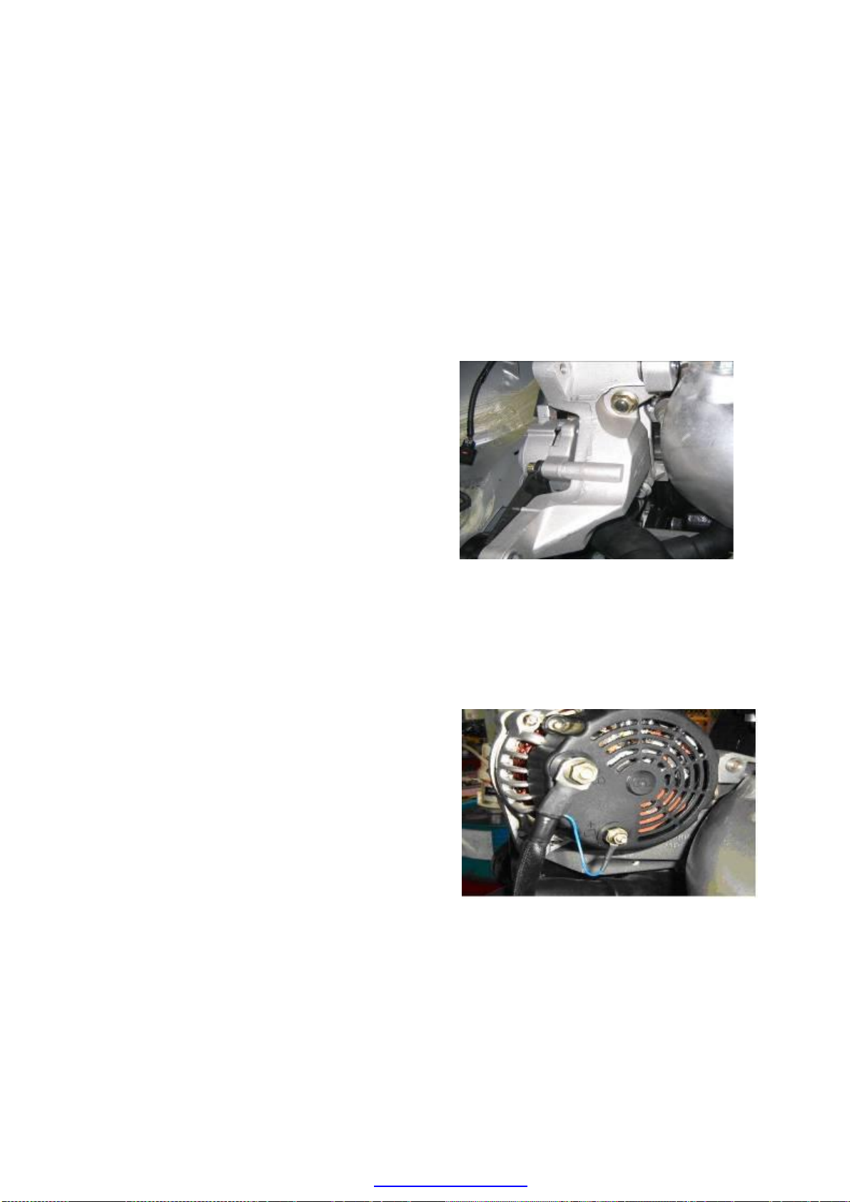
part of the battery away from water.
—Connect the battery to the charger, and adjust
the charging current accordingly.
As heat discharged by the exhaust manifold could damage the generator, you must
ensure that the heat discharging guard and insulation device are firmly installed on the
generator.
Installation of generator bracket:
—Disconnect the negative grid of the battery.
— Mount the double-ended stud on top of
cylinder cover.
—Install the bracket of generator.
—Tighten flange nut of the double-ended stud
and bolt on the cylinder body, the tightening
torque should be 40±4Nm.
The installing steps are reverse to those for
removal.
Installation of generator:
—Disconnect the negative grid of the battery.
—Align one end of the generator with the
installation hole of bracket, and push it in by
force until the installation hole and the shaft
hole of the generator are aligned.
— Use a long bolt and an Allen screw
respectively to install the generator on its
bracket, with a tightening torque of
25±2N.m.
—Connect the positive power source wire with
the generator and the cable lug of the battery
warning lamp to the wiring terminal.
Note: The wiring harness must not be
grounding so as to avoid from
catching fire.
The installing steps are reverse to those for
removal.
T-6
PDF created with pdfFactory Pro trial version www.pdffactory.com
Page 87

Installation of driving belt and tensioner
assembly:
—Disconnect the negative grid of the battery.
— Use 3 M8 Allen screws to install the
tensioner assembly on the bracket of the
generator, with a tightening torque of
25±2N.m.
—Install the multi-wedged belting; Pull out the
pin on the tensioner assembly so as to
tension the driving belts in the tensioner
pulley. Inspect the driving belts to see
whether they are all inserted properly in the
driving wedge of the pulley wheel.
The installing steps are reverse to those for
removal.
Adjusting method of multi-wedge belting
and tensioner assembly alignment:
—Disconnect the negative grid of the battery.
—Use spanner to rotate the engine crankshaft
belt pulley to drive the multi-wedged belting
for at least one revolution.
—Observe the alignment status of the mult i
-wedge belting and tensioner assembly, if
the multi-wedge belting center exceeds the
tensioner assembly center, then remove the
tensioner assembly and add spacers to adjust
the centering.
The installing steps are reverse to those for
removal.
Overhaul of generator:
—Inspect the accuracy of deflexion and
tension value of the driving belt, if it does
not comply with the requirement, then the
driving belts should be replaced.
—Shut down all the electro-devices, turn the
ignition switch to start the engine, inspect
the rotation process of the engine to see
whether the rotation of generator is smooth
without any noise.
T-7
PDF created with pdfFactory Pro trial version www.pdffactory.com
Page 88

—Use voltmeter to measure the voltage value
of the generator output terminal.
Standard value: Engine idling; Temperature: 20
℃, Output voltage: 13-15V.
—Switch on the following devices and observe
the increase of readings of the voltmeter:
• Headlamp
• Air conditioning
• Back window defroster
INSPECTION OF GENERATOR
Warning lamp of generator
1. Confirm that the battery has been fully charged;
● If it necessary, the battery should be charged.
2. Confirm the accuracy of deflexion and tension values of the wedge type belts.
● If it does not comply with the requirement, then replace it with a new type of wedge type
belt.
3. Turn on the ignition switch, and inspect the generator warning lamp to see whether it is
indicating.
● If it does not comply with the specified requirement, then inspect the generator warning
lamp, or check whether the generator connectors are connected firmly.
4. Confirm whether the generator warning lamp is off after the engine is turned off.
● If it does not comply with the requirement, then inspect the instrument connector to see
whether they are connected properly; if the instrument is malfunction free, then you need
to further inspect the generator itself to see whether there is any short circuit.
T-8
PDF created with pdfFactory Pro trial version www.pdffactory.com
Page 89

REMOVAL/INSTALLATION OF STARTER
Warning:
When connecting wires of the battery are in on-state, and at this time if you contact the
generator terminal to the car body, sparks will happen. This may cause body injury, fire
and the sparks may damage the electrical components. Therefore before carrying the
following operation, you must disconnect the negative grid of the battery first.
— Disconnect the negative grid of the
battery.
— Apply lubricating grease of about 5
grams evenly on the inserting shaft of the
starter.
— Insert the starter into housing of the
clutch.
—Screw three bolts and tighten them,(one
of the bolts is M10×1×35), with the
tightening torque of 40±4Nm.
— Connect the wiring harness to the
positive grid of the starter, and the starter
wiring harness connector. Pay attention
not to ground the wiring harness so as to
prevent short circuit and catching fire.
The installing steps are reverse to those
for removal.
OVERHAUL OF STARTER
No load test:
—Verify that the battery is fully charged.
—Close the circuit of the starter, battery, voltmeter and ammeter according to the following
diagram.
—Initiate the starter and check whether it operates smoothly.
—When the starter is rotating, measure its voltage and current values. If these values do not
meet the requirements, then replace the starter.
T-9
PDF created with pdfFactory Pro trial version www.pdffactory.com
Page 90

Technical parameters
Voltage value(V)
Current value
(A)
11 Less than 90
LOAD INSPECTION OF STARTER
1. Verify that the battery is fully charged.
2. Initiate the engine, and check whether any block or noise during the rotation of the starter
rotor.
● If there is no abnormality, then please check the followings:
—Remove the starter and check the solenoid switch and starter.
● Check the related winding coil and ignition switch.
T-10
PDF created with pdfFactory Pro trial version www.pdffactory.com
Page 91

LIGHTING SYSTEM
REMOVAL/INSTALLATION OF LIGHTINGS FOR THE COMPLETE CAR
1. Headlamp
Removal (Disconnect the negative grid of
the battery)
—Remove the radiator grille, and use sleeve to
remove the four fixing bolts of the
headlamp.
—Unplug the wiring harness connector behind
the headlamp holder.
— Then place the headlamp on the
corresponding position.
Installation
— Install the headlamp properly on the
corresponding position, and ensure that the
fixing hole position of the bolt is concentric
with the welded nut on the crossbeam of the
headlamp;
—Use 4 bolts, spacers and 1 nut to locate the
position of the front headlamp, put down the
front hood, confirm and adjust position of
the headlamp (whether it is extruding or
intruding; the requirement is such that the
headlamp should be slightly extruded
beyond the front hood border. The arc shape
of the headlamp can be felt by hand), after
that tighten the fastener, with a tightening
torque of 1.5±0.2 N.m;
—Install the radiator grille, and pay attention
not to scratch the paint on the protection
bumper; ensure that the spacing between the
left and right fenders is symmetrical.
—Connect the wiring harness plug to the lamp
holder socket.
2. Removal/Installation of the front fog lamp: (Disconnect the negative grid of the
battery)
—Connect the corresponding connector to the wiring harness of the fog lamp;
T-11
PDF created with pdfFactory Pro trial version www.pdffactory.com
Page 92

—Place the fog lamp into the installation hole from the front, and ensure that the 3 screw
holes are concentric with the holes on the front bumper;
—Tighten the 3 self-tapping screws, with a tightening torque of 1.5±0.2N.m;
—Install the grilles on the bottom part (see instruction in car body)
3. Removal/installation of side turn signal lamp: (Disconnect the negative grid of the
battery)
—Connect the wiring harness from the lamp holder;
—First align the clipping end with car body in the correct direction, and then press it in by
force.
4. Removal/installation of fixed part of tail
lamps (including position lamp/brake lamp,
and turn signal lamp):
—Align at the holes of car body, so as to install
the lamp on the body properly;
—Tighten the 3 fixing screws, pay attention to
adjust the facial gap with the car body, feel
the difference in height with hand and make
necessary adjustment while tightening;
— Plug the wiring harness onto the lamp
holder, and put back the carpet.
5. Removal/installation of moving part for
the tail lamp (including the backup lamp
and tail fog lamp)
—Align at the holes of the car body, so as to
install the lamp on the body properly;
—Tighten the 4 fixing screws, pay attention to
adjust the facial gap and spacing (the trunk
lid may be closed) with the car body and
fixing parts, feel the difference in height
with hand and make necessary adjustment
while tightening;
— Plug the wiring harness onto the lamp
holder, and put down the trunk lid.
6. Removal/installation of license lamp
—Connect the connector of the wiring harness properly;
—Align the self-tapping screw with the hole center of expansion nut; tighten two self-tapping
screws with a tightening torque of 1.5±0.2N.m. Assemble the guard plate of license lamp;
T-12
PDF created with pdfFactory Pro trial version www.pdffactory.com
Page 93

8. Removal/installation of trunk lamp
—Align lock core of the trunk with the hole, so as to match the guard plate with the car body
properly;
—Tighten 2 self-tapping screw, pay attention to adjust the facial gap, spacing and other
differences between the car body and the movable part, feel the difference in height with
hand and make necessary adjustment while tightening;
—Open the trunk lid;
—Tighten 2 square nuts of the fixing bolt;
—Assemble the linkage rod, lid, etc. of the lock hole (see instruction of car body), and then
put down the trunk lid.
7. Removal/installation of interior ceiling
lamp
—Connect the connector of the wiring harness
properly;
—Place it right into the installation hole of the
ceiling towards the correct direction, firstly
align one end with the ceiling and then press
the ceiling light into the proper position with
hand.
—Open the trunk lid;
—Connect the connector of the wiring harness properly;
—Use the clipping end side to latch with cover of the back loudspeaker, after that just press
the light into it with hand. Put down the trunk lid;
9. Removal/installation of high mounted stop lamp
—Press the two ends so as to separate the lamp holder and the lamp housing, and then pull out
the conducting wire connector;
—Plug both of the single-terminal sockets of the conducting wires into the inserting plates of
the windscreen;
—Install the lamp housing according to the combination structure of the clipping slot, pay
attention to the matching of the inverted slot with the fixing pin, so as to ensure that the
lamp housing is firmly clipped to the position;
—Plug the conducting wire and lamp holder properly, and ensure that the lamp holder and
housing are assembled in the proper position.
T-13
PDF created with pdfFactory Pro trial version www.pdffactory.com
Page 94

10.Removal/installation of door switch
—Disconnect the negative grid of the battery.
—Loosen the self-tapping screw of the door switch with a cross screw driver.
—Pull out the door switch, and separate the wiring harness connectors.
11.Removal/installation of control switch for dash lights
—Disconnect the negative grid of the battery.
—Reach the bottom part of the instrument panel with hand, and press down the clip of the
control switch for dash lights.
—Pull the control switch for dash lights forward and remove it.
The installing steps of above components are reverse to those for removal
12. Beam adjustment for headlamp
—The correctness of the beam adjustment for front headlamp is vital to the driving safety.
Therefore, only special instruments are allowed to be used to adjust the beam, and pay
attention to the stipulated laws during adjustment.
13. The followings must be fulfilled before adjustment
—Air pressure of car tyres must comply with the standard;
—The vehicle should be non-load (other than the spare tyre and tool kit, the weight of the car
normally includes the weight of the driver);
—The car should be parked on a horizontal road or working site;
—The surface of the headlamp reflector must be clean without any contamination;
—Check whether power works normally and bulbs are installed properly.
—Two screws linking the front headlamp can be adjusted towards the horizontal or vertical
position.
—When adjusting the front right headlamp, the protection cover must be removed. The
adjustment screw for the front left headlamp is symmetrical with the front right one. The
adjustment method is the same.
T-14
PDF created with pdfFactory Pro trial version www.pdffactory.com
Page 95

COMMON MALFUNCTIONS OF LIGHTING SYSTEM / TROUBLESHOOTING
1.COMMON MALFUNCTIONS OF FRONT HEADLAMP / TROUBLESHOOTING
Malfunction Malfunction Diagnosis Troubleshooting
Neither high beam or low
beam light is working
1.All of bulbs have been damaged.
2.The fuse has been burned down.
3.Headlamp switch is faulty.
4.The circuit is faulty.
1.Replace the bulb.
2.Replace the fuse.
3.Inspect and replace the
headlamp switch.
4.Check the circuit.
Only one headlamp, that
is either the high beam or
low beam is working
Either side of the high
beam or low beam is not
working.
Both headlamps are not
working.
1.The bulb has been damaged.
2.The fuse has been burned down.
3.The lamp holder or conducting
wire is faulty.
1.The bulb has been damaged.
2.The fuse has been burned down.
3.The headlamp switch is faulty.
4.The conducting wire or the
grounding is faulty.
1.The bulb has been damaged.
2.The fuse has been broken.
3.The headlamp switch is faulty.
4.The conducting wire or the
grounding is faulty.
1.Replace the bulb.
2.Replace the fuse.
3.Check the lamp holder
or conducting wire.
1.Replace the bulb.
2.Replace the fuse.
3.Check the headlamp
switch.
4.Inspect the circuit.
1.Replace the bulb.
2.Replace the fuse.
3.Check the headlamp
switch.
4.Check the circuit.
Warning:
● The bulb will generate heat of very high temperature during working. So if the
surface of the bulb becomes dirty, the excessive heat will be accumulated, which
would result in shortening the life span of the bulb. When replacing the bulb, pay
attention to hold the metal edge rather than the bulb itself.
2. COMMON MALFUNCITONS OF FOG LAMP AND TROUBLESHOOTING
Malfunction symptom Malfunction Diagnosis Troubleshooting
Only one fog lamp is not
working
Neither of fog lamps is
not working
Fog lamp is always
working
1. The bulb has been damaged.
2. The circuit or grounding is faulty.
1. The bulb has been damaged.
2. The fuse has been burned down.
3. The fog lamp relay has been
damaged.
4. The fog lamp switch is faulty.
5. The circuit or grounding is faulty.
1. The switch of fog lamp is faulty.
2. The circuit is faulty.
1. Replace the bulb.
2. Check the circuit.
1. Replace the bulb.
2. Replace the fuse.
3. Check the relay.
4. Check the switch.
5. Check the circuit.
1. Check the switch.
2. Check the circuit.
T-15
PDF created with pdfFactory Pro trial version www.pdffactory.com
Page 96

Warning:
● The bulb will generate heat of very high temperature during working. So if the
surface of the bulb becomes dirty, the excessive heat will be accumulated, which
would result in shortening the life span of the bulb. When replacing the bulb, pay
attention to hold the metal edge rather than the bulb itself.
3. COMMON MALFUNCTIONS OF BACKUP LAMP AND TROUBLESHOOTING
Malfunction symptom Malfunction Diagnosis Troubleshooting
One side of the backup
lamp is not working
Neither sides of the
backup lamps is not
working
Backup lamp is
continuously working
1. The bulb has been damaged.
2. The circuit or grounding is faulty.
1. The bulb has been damaged.
2. The fuse has been burned down.
3. The backup lamp switch is faulty.
4. The circuit or grounding is faulty.
Incorrect adjustment or damage to the
switch of backup lamp.
1. Replace the bulb.
2. Check the circuit.
1. Replace the bulb.
2. Replace the fuse.
3. Check the switch.
4. Check the circuit.
Check the backup
lamp switch.
4. COMMON MALFUNCTIONS OF STOP LAMP AND TROUBLESHOOTING
Malfunction symptom Malfunction Diagnosis Troubleshooting
One side of the brake
lamps is not working
Neither of the brake
lamps is not working
Brake lamp is
continuously working.
1 The bulb has been damaged.
2. The conducting wire or grounding is
faulty.
1. The bulb has been damaged.
2. The fuse has been burned down.
3. The brake lamp switch is faulty.
4. The conducting wire or grounding is
faulty.
Incorrect adjustment or damage to the switch
of backup lamp.
1. Replace the bulb.
2. Check the circuit.
1. Replace the bulb.
2. Replace the fuse.
3. Check the brake
lamp switch.
4. Check the circuit.
Check the brake
lamp switch.
T-16
PDF created with pdfFactory Pro trial version www.pdffactory.com
Page 97

5. COMMON MALFUNCTIONS OF TURN SIGNAL LAMP AND
TROUBLESHOOTING
Malfunction
symptom
Left and right
flashing
frequencies are
not the same or
one side is not
flashing.
Both sides are not
flashing
The flashing
frequency is too
low
Malfunction Diagnosis Troubleshooting
1. The bulb of the “fast flashing
frequency” side has been damaged.
2. The bulb power does not comply with
the specification.
3. The relay of turn signal lamp is faulty.
4. The conducting wire or grounding is
faulty.
1. The bulb has been damaged.
2. The fuse has been burned down.
3. The relay of turn signal lamp is faulty.
4. The switch of turn signal lamp is
faulty.
5. The conducting wire or grounding is
faulty.
1. Battery voltage is too low.
2. The bulb power does not comply with
specification.
3. The relay of turn signal lamp is faulty.
4. The circuit is faulty.
1. Replace the bulb.
2. Replace the standard bulb.
3. Check and replace the
relay.
4. Check the circuit.
1. Replace the bulb.
2. Replace the fuse.
3. Check the relay.
4. Check the switch of turn
signal lamp.
5. Check the circuit.
1. Check the battery and
recharge battery.
2. Change into the standard
bulb.
3. Check/replace the relay.
4. Check the circuit.
T-17
PDF created with pdfFactory Pro trial version www.pdffactory.com
Page 98

IGNITION SYSTEM
SUMMARY OF IGNITION SYSTEM
The ignition system is integrated with the fuel injection system. It is an electronic system
equipped with built-in power supply module. It can provide various kinds of optimum
ignition angular values. This task is being carried out through referencing of the input
instantaneous physical parameter related with the engine working conditions. With the help
of a circuit analyzing microprocessor, it is capable of writing in the various optimum ignition
values into the program.
Circuit of ignition system
1. Knock sensor 2. Ignition coil 3. Rotary sensor 4. Ignition switch
5. Relay 6. Ignition / Fuel injection ECU 7. Fuse
When ECU is breaking off the current of the primary coil, the resulted induction effect of the
secondary coil causes the voltage to rise (as high as 30,000V at idling speed), at this moment
the breakdown voltage of the compression stroke stage in the cylinder is very high
(>10,000V), and the breakdown voltage of the exhaust stroke stage in the cylinder is very low
(approx. 500V). The spark plugs in the 1-4 cylinders and 2-3 cylinders are directly connected
to the terminals of the secondary coils through high voltage cables.
Note: Take extreme care not to reverse the connection of high voltage cable during
reinstallation.
T-18
PDF created with pdfFactory Pro trial version www.pdffactory.com
Page 99

REMOVAL /INSTALLATION OF IGNITION COIL AND SPARK PLUGS:
1. Disconnect the wiring harness terminal post
from the negative grid of the battery.
2. Pull out the 4 connectors of high voltage cable
and ignition module plug.
3. Unscrew the three fastening screws for the
ignition module, and remove the ignition
module.
4. Pull out the high voltage cables, and uses a
special spark plug socket spanner to remove
the spark plugs. (Tightening torque: 10~14
Nm)
5. The installing steps are reverse to those for
removal.
Note:
Ensure that the spark plugs are restored to their
original positions during reinstallation. Any
incorrect installation will not only damage the
leading wires of the spark plugs and cause power
losses, but also cause adverse impact to the electronic
components.
T-19
PDF created with pdfFactory Pro trial version www.pdffactory.com
Page 100

OVERHAUL IGNITION SYSTEM
----Disconnect the negative grid of the battery.
----Remove the spark plugs with a special tool, and check whether the spark plugs have been
ablated and there is any crack at the skirt section.
----Check whether the gap of spark plugs complies with the requirement.
Standard value: 1.1±0.5mm
----Check the spark plugs.
Note:
l Do not check, adjust or clean the gap of spark plugs with a metal brush. Otherwise, it
will damage the platinum igniter.
When spark plugs are cleaned with compressed gas, the cleaning process should be
completed within 20 seconds and the compressed gas value should not exceed 58.8kpa
(6.6kgf/cm2, 8.5psi). After completion of cleaning, make sure that no foreign materials
such as carbon or sand are left in spark plugs.
----Check whether there is any crack on the appearance of high voltage cables, and replace
the high voltage cable if the resistance is too high.
----Check whether the resistance of ignition coils complies with the specification.
Standard value: Primary coil resistance: 0.4Ω ±10%(at the temperature of 23±5°C)
Secondary coil resistance: 4900Ω±10%(at the temperature of 23±5°C)
If the resistance of ignition coils does not comply with the specification, please replace with
the original spare parts designated by Chery Automobile so as to prevent the improper
operation of the ignition system.
Inspection of ignition timing:
Note:
·The ignition timing must not be adjusted.
·Checking the ignition timing requires the usage of WDS or corresponding instrument.
1. Switch off all the electrical devices in the vehicle.
2. The procedures of preheating the engine are as follows:
(1) Start the engine
(2) Keep the rotation speed of the engine at about 3,000 R.P.M. until the cooling fan starts to
rotate.
(3) Release the fuel-accelerating pedal.
T-20
PDF created with pdfFactory Pro trial version www.pdffactory.com
 Loading...