

Chery A113 Maintenance Manual

Maintenance Manual of Chery A113
(Chassis)
Chery Automobile Co., Ltd

CONTENT
Chapter 1 Brake System.................................................................................................................4
I. System Checking Parameters..................................................................................................4
1. Check brake disc.....................................................................................................................4
2. Thickness checking.................................................................................................................4
3. Checking of brake friction lining thickness............................................................................4
4. Checking of brake disc run-out..............................................................................................4
II. Removal/Installation and Overhaul of Front Brake and Brake Calliper...........................5
1. System Structural Diagram.....................................................................................................5
2. Preparations............................................................................................................................6
3. Notices....................................................................................................................................6
4. Removal and Overhaul...........................................................................................................6
III. Removal/Installation and Overhaul of Rear Brake..........................................................10
1. System Structural Diagram...................................................................................................10
2. Preparations..........................................................................................................................10
3. Notices..................................................................................................................................10
4. Removal Procedure..............................................................................................................11
4. Installation Procedure...........................................................................................................13
IV. Adjustment and Replacement of Handbrake....................................................................14
1. System Composition Illustration..........................................................................................14
2. Preparations..........................................................................................................................14
3. Notices..................................................................................................................................14
4. Removal/Installation Procedure...........................................................................................14
Chapter 2 Adjustment of Suspension System and Four-Wheel Alignment...............................18
I. Removal/Installation and Overhaul of Front Axle and Suspension...................................18
1. System Structural Diagram...................................................................................................18
2. Preparations..........................................................................................................................20
3. Notices..................................................................................................................................20
4. Removal/Installation Procedure...........................................................................................20
4.1 Removal of Shock absorber assembly............................................................................20
4.2 Removal of Control Arm Assembly...............................................................................21
4.3 Removal of Front Axle Assembly...................................................................................22
5. Installation Procedure...........................................................................................................24
II. Removal/Installation and Overhaul of Rear Axle and Suspension...................................25
1. System Structural Diagram...................................................................................................25
2. Preparations..........................................................................................................................26
3. Notices..................................................................................................................................26
4. Removal/Installation Procedure...........................................................................................26
4.1 Removal of Shock Absorber Assembly and Shock Absorber Spring.............................26
4.2 Cross Stay Assembly......................................................................................................27
4.3 Rear Trailing Arm Assembly..........................................................................................27
4.4. Removal of Rear Axle Assembly...................................................................................28

5. Installation Procedure...........................................................................................................29
III. Adjustment of Four-Wheel Alignment...............................................................................30
1. Adjustment of Front Wheel Toe-In......................................................................................30
2. Adjustment of Front Wheel Camber Angle..........................................................................30
3. Adjustment of Caster Angle and Kingpin Inclination..........................................................30
4. Adjustment of Rear-Wheel Alignment Parameters..............................................................31
IV. Tire Installation and Air Pressure Adjustment.................................................................31
1. Installation of Air Valve.......................................................................................................31
2. Tire Assembling...................................................................................................................31
3. Tire Inflation.........................................................................................................................32
4. Installation of Wheel and Tire Assembly.............................................................................32
5. Tightening Method of Wheel Bolts......................................................................................32
6. Installation of Decorative Cover...........................................................................................32
Chapter 3 Removal/Installation and Overhaul of Steering System............................................33
I. Removal/Installation of Steering Gear..................................................................................33
1. System Composition Illustration..........................................................................................33
2. Preparations..........................................................................................................................34
3. Notices..................................................................................................................................34
4. Removal/Installation Procedure...........................................................................................35
5. Installation Procedure...........................................................................................................36
II. Removal/Installation of Steering Column...........................................................................37
1. System Composition Illustration..........................................................................................37
2. Preparations..........................................................................................................................37
3. Notices..................................................................................................................................37
4. Removal Procedure..............................................................................................................38
5. Installation Procedure...........................................................................................................43
III. Adjustment of Steering Gear Clearance............................................................................44
IV. Adjustment of Power Steering System................................................................................44

Chapter 1 Brake System
I. System Checking Parameters
1. Check brake disc:
The friction surface of brake disc should be flat and has no apparent grooves; otherwise, brake disc should be
replaced.
2. Thickness checking
The standard thickness of front disc (ventilation disc) is 17 mm with its operating limit of 15 mm; when
exceeding the operating limit, the front disc should be replaced.
3. Checking of brake friction lining thickness
Standard thickness of front brake lining shall be 10 mm, application limit shall be 1 mm, and the remaining
thickness of limit brake pad thickness shall be not less than 1mm.
Standard thickness of rear brake lining shall be 5 mm, application limit shall be 1 mm, and the remaining
thickness of limit brake pad thickness shall be not less than 1 mm.
4. Checking of brake disc run-out
Use dial gauge to check the face runout of brake disk, the application limit of front disk shall be 0.03mm, the
application limit of rear disk shall be 0.03mm, otherwise replace it.
Important notice:
After completion of replacing friction lining or brake disk, apply the brake for several times to enable breaking-in
between brake lining and brake disk. Always ensure safety!
After replacing brake lining, check brake fluid level to ensure it is between MIN and MAX.
II. Removal/Installation and Overhaul of Front Brake and Brake Calliper
1. System Structural Diagram
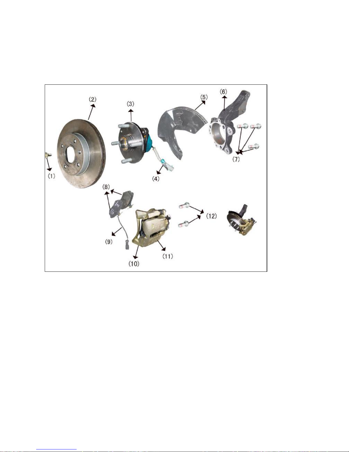
Structural Diagram of Front Brake Assembly
(1) Brake disc positioning bolt (2) Brake disc
(3) Wheel hub bearing unit; (4) ABS speed sensor plug
(5) Dust cover (6) Steering joint
(7) Fixing bolt (8) Friction lining
(9) Friction lining thickness sensor plug (10) Brake bracket
(11) Brake calliper assembly (12) Fixing bolt
2. Preparations
Tools: Ratchet wheel, ratchet lever, 13#, 14#, 16#, 18#, 19#, 8#,
30# socket, 10#, 13#, 14#, 16# ring wrench, vice,
torque wrench, measure ruler..
Accessories: brake fluid
3. Notices
3.1 Please wear necessary labor protection supplies to avoid
accidents.
3.2 The brake liquid is one toxic liquid. In event of contact with the
skin or eyes due to carelessness, flush with a great amount of water
and if necessary call for medical treatment timely.
3.3 The scrapped brake liquid should be accommodated in the
container. It’s prohibited to drain it into the sewage system or stack
with other household garbage.
3.4 Do not depress the brake pedal nor move the vehicle during the
removal/installation operation.
3.5 Do not make the friction lining or brake disc come contact with
the oil substances, which will impair the braking effects.
4. Removal and Overhaul
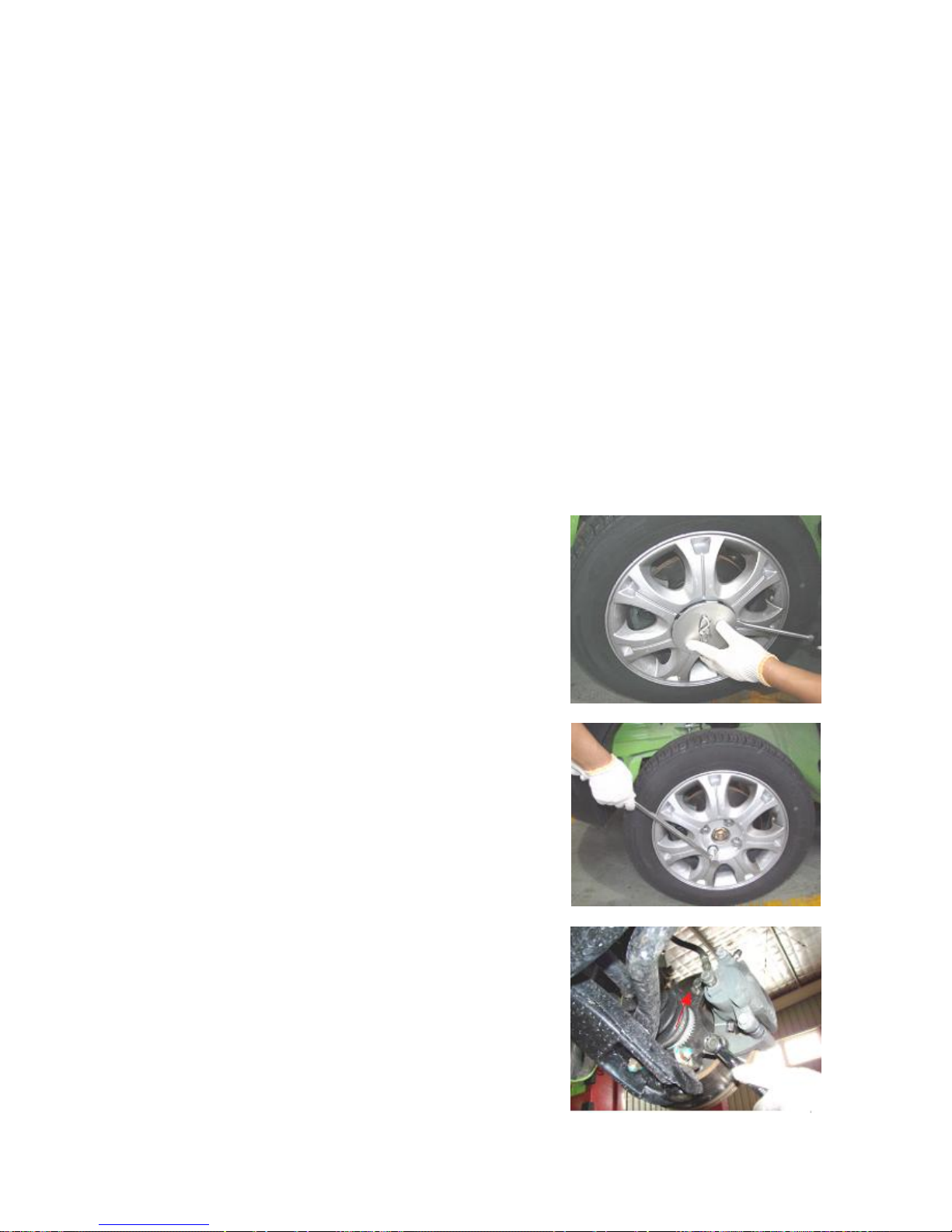
4.1 Remove the protective cover from the tire rim with slotted
screwdriver.
4.2 Remove the tire fixing nuts with 19# torque wrench or vehicle
attached tool and remove the tire.
Torque: 110±10 Nm.
4.3 Lift the vehicle with elevator.
4.4 Remove the 2 nuts (upper and lower) from
the brake calliper and steering joint with 18# wrench.
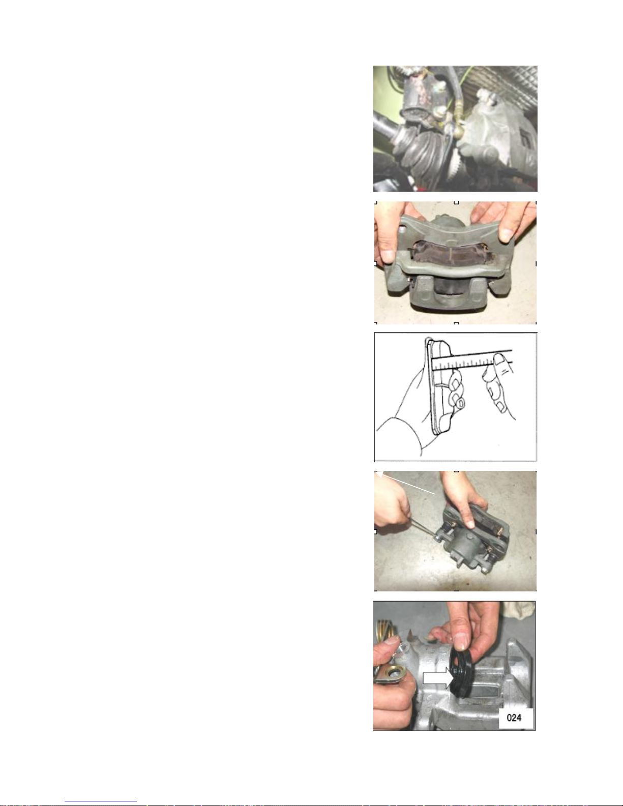
4.5 Remove the nuts from brake hose with 13# wrench.
Notice: The brake liquid is one toxic liquid. Do not splash the brake
liquid to the clothes or skin during the removal of the brake hose.
Torque: 16±3 Nm.
4.6 Pull out the brake disc with hand.
4.7 Measure the thickness of friction lining. If below 3mm, replace
timely in pairs.
4.8 Remove the brake calliper and brake pump with 14# wrench.
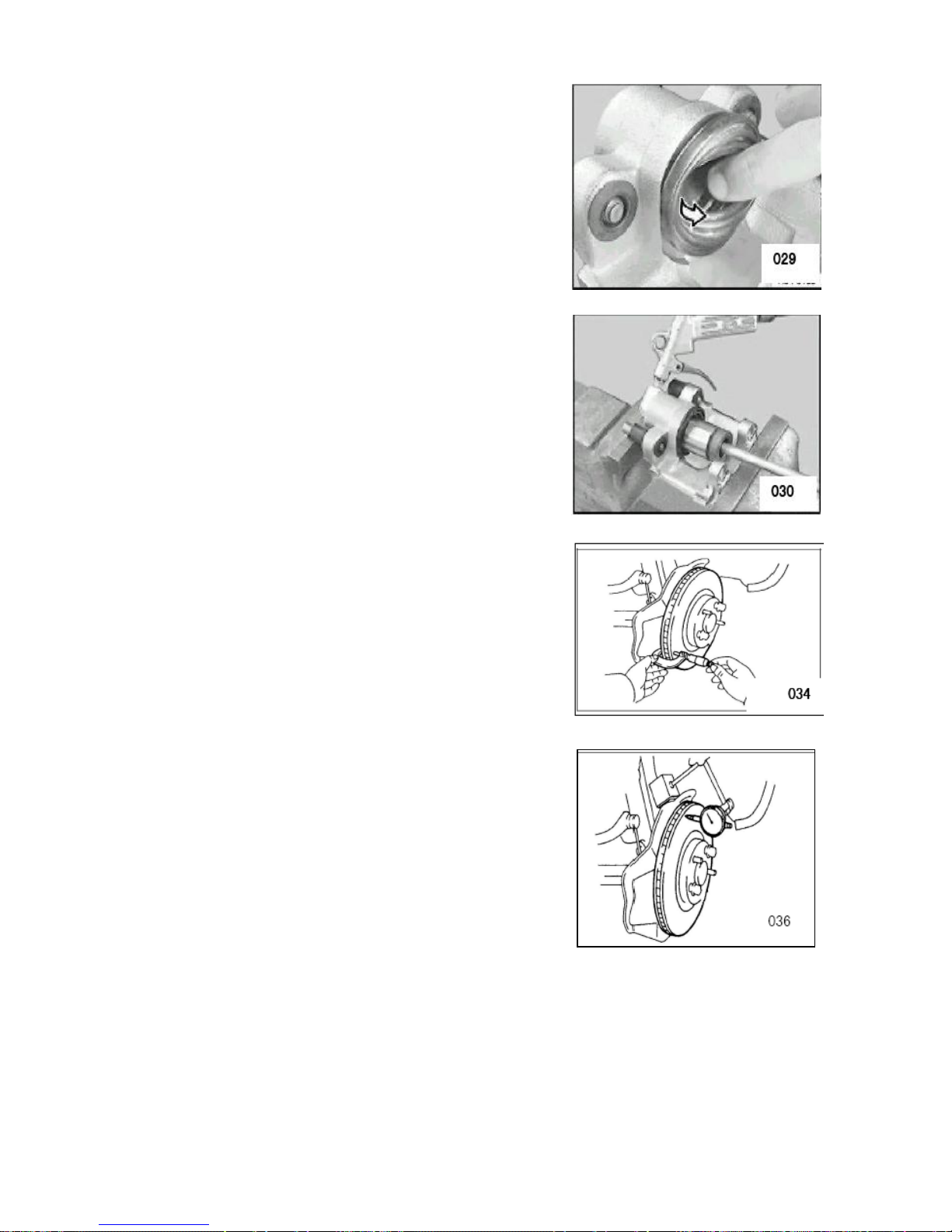
4.9 Remove the dustproof seal and check for the damage of the
dustproof seal. If necessary, renew the dustproof seal. Clean the
contact surface of the brake piston and apply with one film of
silencing grease.
Notice: It's prohibited to make the dustproof seal come contact with
the silencing grease, which will cause the swelling of the dustproof
seal.
4.10 Remove the piston. Prepare one wood board to hold the piston
and place the wood board between the piston and the wall of the
brake calliper. Press out the piston with the compressed air carefully
through the connecting bore. Place the guard plate (such as hard
wood) at the notch of the brake calliper to protect the piston.
Notice: Do not hold the piston with fingers – danger of clamping!
The brake calliper piston is prohibited from removal at will and
should be removed/installed only by professionals or under the
guidance of the professionals.
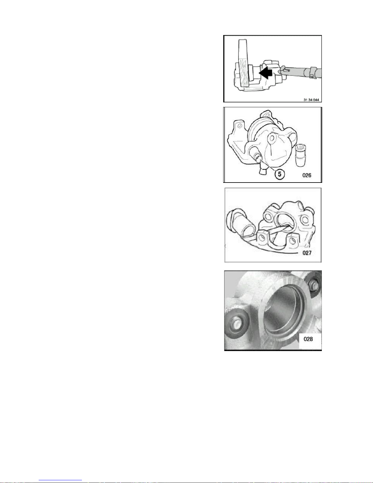
4.11 Check the guide sleeve. The guide sleeve should move
smoothly and freely when pushed with hand. Replace the guide
sleeve in event of jamming or stiffness. Notice: Apply the
lubricating grease onto the guide sleeve during assembling.
4.12 Remove the seal ring carefully with the plastic needle, clean the
brake cylinder and components with alcohol and blow dry with
compressed air. Carefully check the surfaces of brake cylinder,
piston, and flange. It’s prohibited to conduct the machining process
on the brake cylinder and piston.
4.3 Installation of brake branch pump: Apply one film of brake
cylinder cream onto the cylinder body, plunger, and seal sleeve.
Attach the seal ring onto the circular groove at the rear of the brake
cylinder. Attach the dustproof seal ring onto the front circular groove
and press it in completely.
4.14 The area between the dustproof seal ring and the brake clamp
housing must be kept dry. It should be kept away from the brake
cylinder cream or the brake liquid, in order to ensure the correct
position of dustproof seal ring.
4.15 Secure the brake piston with the reinforcement parts available
in market and press it onto the dustproof seal ring slightly. Blow the
dustproof seal ring with compressed air (up to 3.0bar) to attach the
piston ring onto the piston.
Notice: Dip the dustproof seal ring and piston with brake
liquid to facilitate the passing of the seal ring.
4.16 (Checking of brake disc) Check the thickness of brake disc.
Replace the brake disc if the thickness is less than the min thickness.
Notice: The two brake discs at the same axle should be replaced at a
time. The friction linings must be replaced following the
replacement of the brake discs.
4.17 Check the max run-out of the end surface of brake disc with
dial gage. If above 0.03mm, replace it. (Provided that the brake disc
thickness is guaranteed, it may conduct the proper machining to
meet with the max run-out.)
4.18 Installation of other portions with reference to the Removal
Procedure.
III. Removal/Installation and Overhaul of Rear Brake
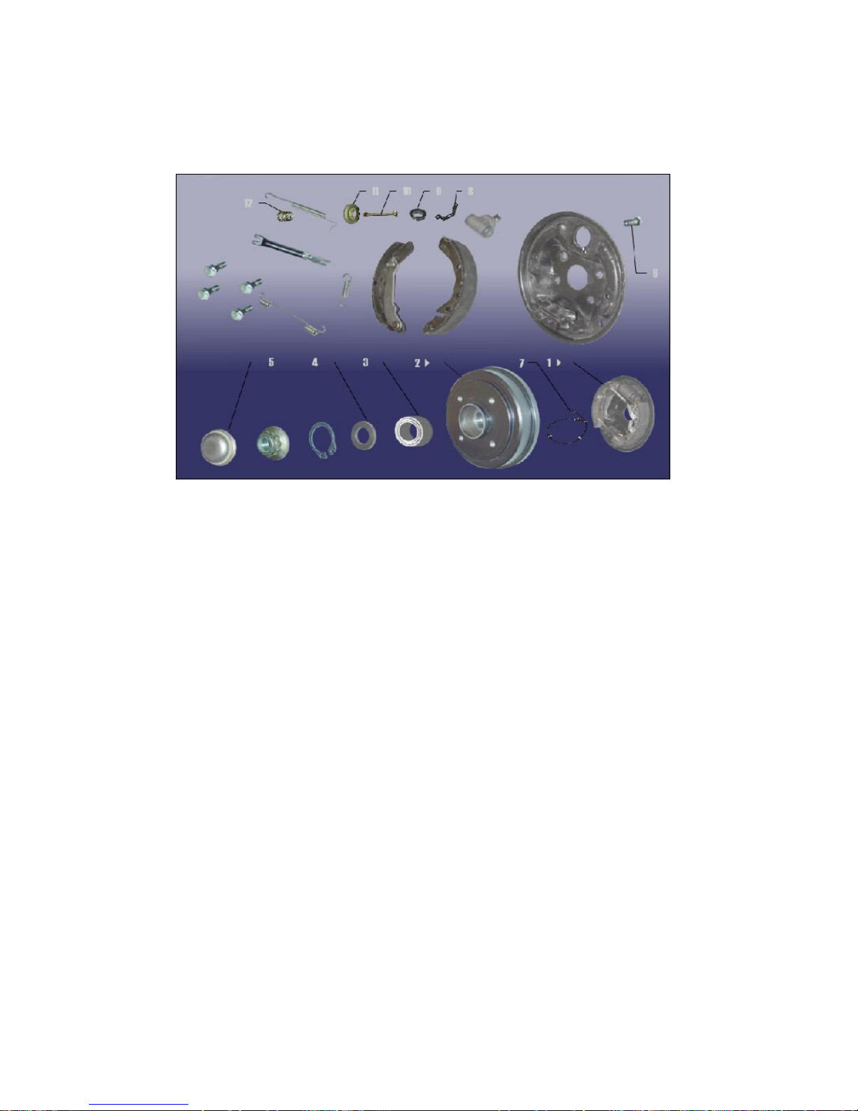
1. System Structural Diagram
1. Rear brake assembly 2. Brake drum
3. Rear wheel hub bearing assembly 4. Oil seal
5. End cap 6. Bolt
7. Rear wheel sensor 8. Rear brake hose retaining clip
9. Dual-port pipe clip 10. Tie rod
11. Rear shoe pressure spring plate 12. Rear shoe pressure spring
2. Preparations
Tools:
Ratchet wheel, ratchet lever, 10#, 19#, 32# socket, 10# ring wrench,
vice, torque wrench, slotted screwdriver.
Accessories: brake fluid
3. Notices
3.1 Please wear necessary labor protection supplies to avoid
accidents.
3.2 The brake liquid is one toxic liquid. In event of contact with the
skin or eyes due to carelessness, flush with a great amount of water
and if necessary call for medical treatment timely.
3.3 The scrapped brake liquid should be accommodated in the
container. It’s prohibited to drain it into the sewage system or stack
with other household garbage.
3.4 Do not depress the brake pedal nor move the vehicle during the
removal/installation operation.
3.5 Do not make the friction lining or brake disc come contact with
the oil substances, which will impair the braking effects.
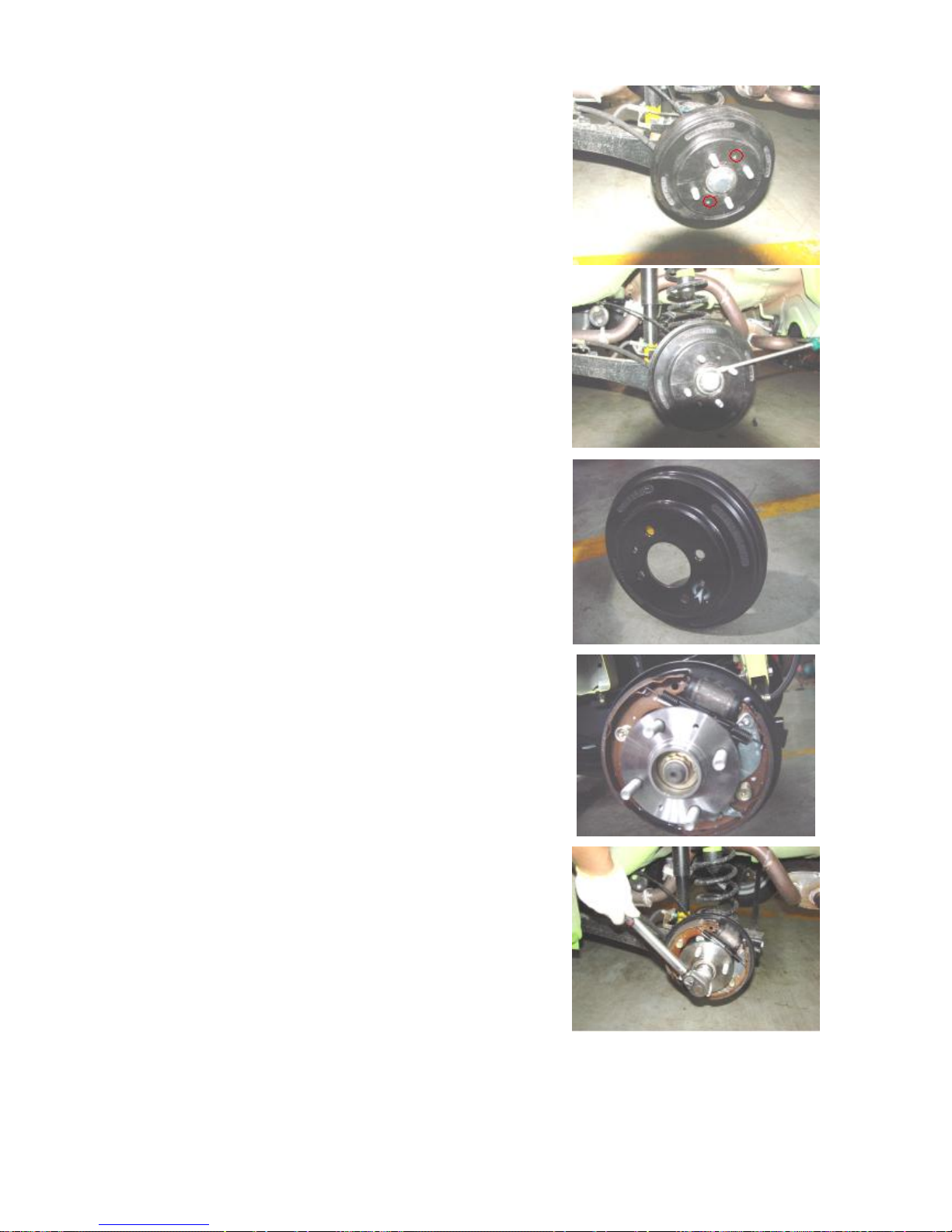
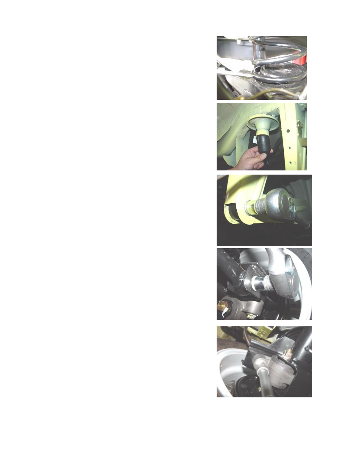
4. Removal Procedure
4.1 Remove the rear wheels (see the removal procedure of front
wheels).
4.2 Remove two position bolts from the brake drum with the cross
screwdriver.
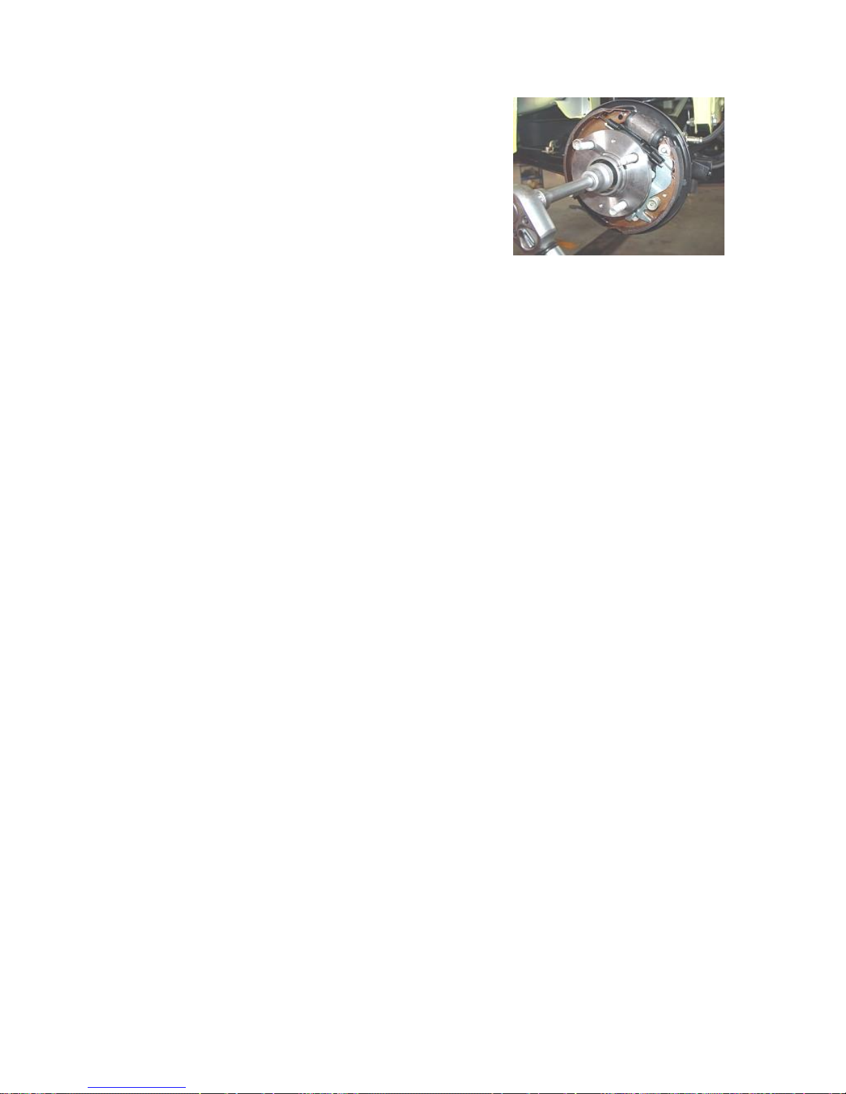
4.3 Remove the bearing dust cap with slotted screwdriver.
4.4 Vibrate the brake drum to remove it.
4.5 Observe the rear braking structure.
4.6 If it’s necessary to check the brake drum bearing, remove the
lock nuts shown in the figure with 30# socket and torque wrench
and remove the brake drum bearing.
Torque: 250±10 Nm
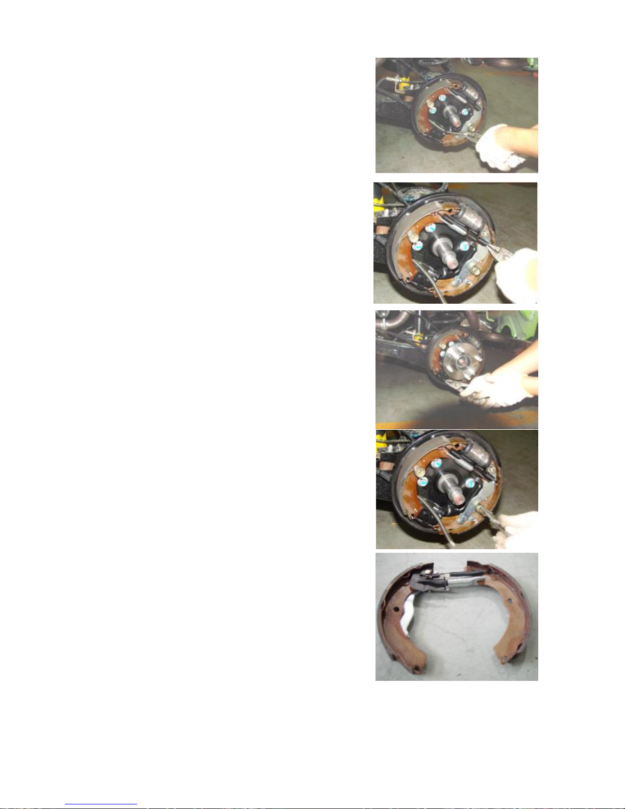
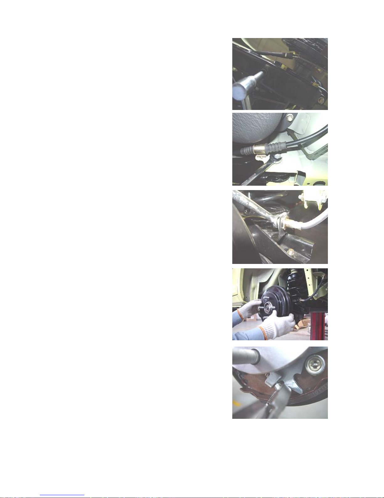
4.7 Remove the handbrake cable with calliper.
4.8 Remove the upper return tension spring with calliper.
4.9 Remove the lower return tension spring with calliper.
4.10 Depress the spring strip of the brake shoe positioning tie rod
with calliper and then rotate clockwise or counter clockwise for 90°
to remove two brake shoe position tie rods.
4.11 Pull out two brake shoes.
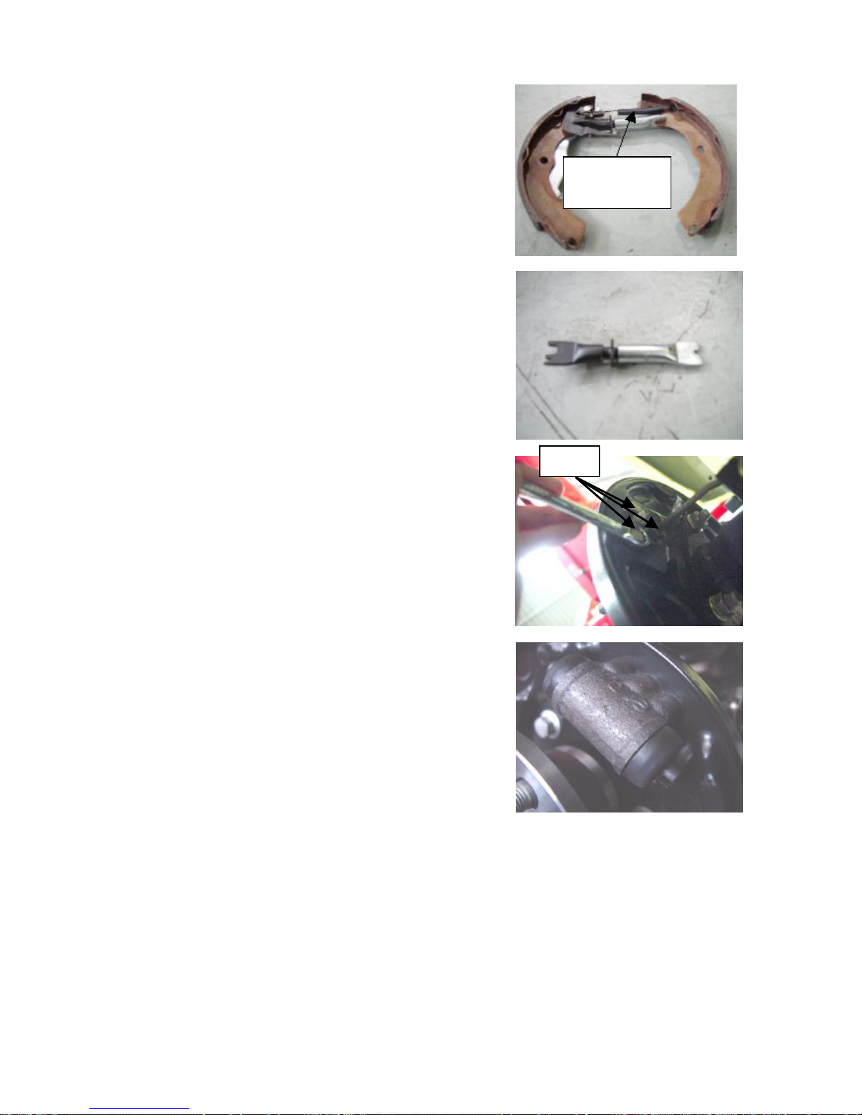
4.12 Remove the tension spring to separate the brake shoe.
Remove this
4.13 In the event of detection of over-tight rear brake, it may adjust
the length of the push rod: Rotate clockwise to eliminate the friction.
4.14 Remove the three bolts shown in the figure with 10# ring
wrench.
4.15 Remove the branch pump and break it down for checking of
intactness.
tension spring.
Bolts
4. Installation Procedure
Refer to removal procedures.

IV. Adjustment and Replacement of Handbrake
o left
1. System Composition Illustration
1. Handle 2. Fixing bolts 3. Cable 4, 5. Left/Right rear wheel cable
To right
rear
brake
assembly
T
rear
brake
assembly
2. Preparations
Tools: Ratchet wheel, ratchet lever, 10#, 13#, 14#, 16# socket, 10#
13#, 14# ring wrench, vice, torque wrench, slotted screwdriver.
3. Notices
3.1 Please wear necessary labor protection supplies to avoid accidents.
3.2 During the removal/installation of the spring parts, enough cautions should be taken to prevent the ejection
of such parts from causing body injuries.
3.3 The removal/installation at the vicinity of the exhaust pipe must be conducted only after the temperature of
the exhaust pipe is lowered to normal temperature so as to prevent scald.
4. Removal/Installation Procedure
4.1 With reference to the removal/installation of the rear brake,
loosen the handbrake cable of the rear wheels.
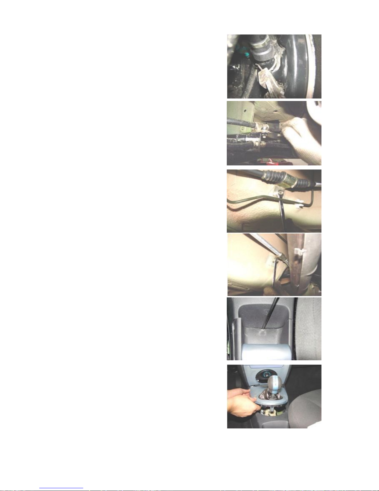
4.2 Remove the handbrake clip with priers.
Notice: It’s under the rear wheels.
4.3 Remove the fixing bracket bolts of the handbrake cable shown
below with 8# ring wrench.
Torque: 9~12 Nm
4.5 Pry out the protective cover at the handbrake and gear position
with slotted screwdriver.
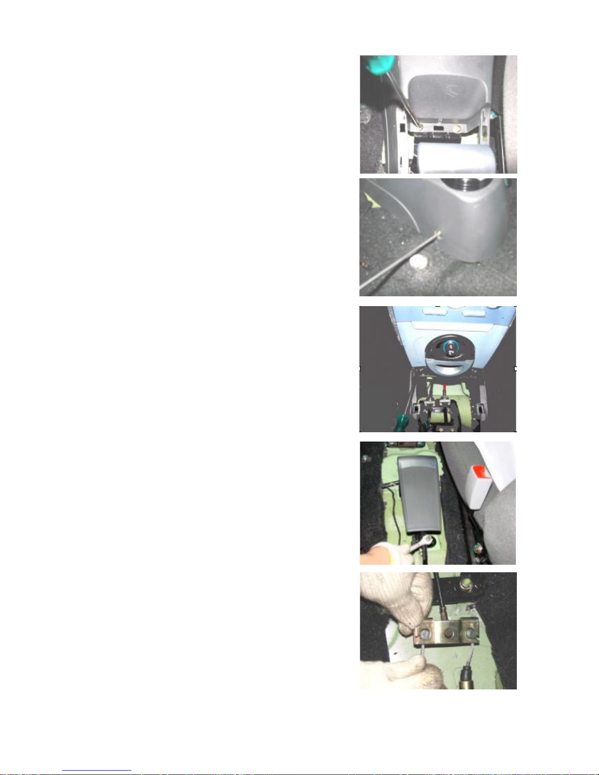
4.6 Remove all fixing screws from the secondary instrument panel
assembly with ring screwdriver to remove the secondary instrument
panel assembly.
4.7 Remove the handbrake adjustment nuts with 10# wrench.
4.5 Loosen the two handbrake cables with hand.
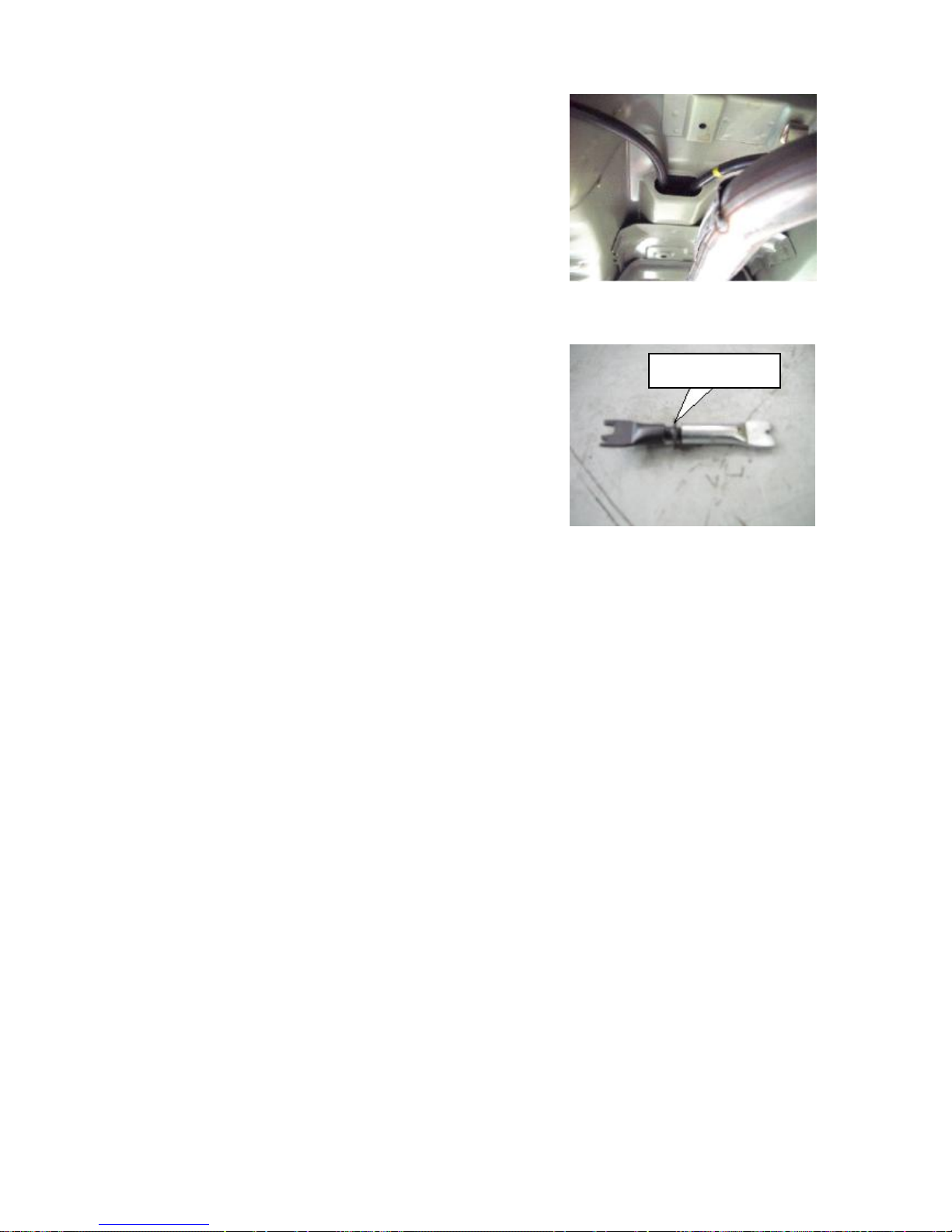
4.9 Pull out the handbrake cable from the underside of the vehicle
body.
Notice: Remove the handbrake cable at another side in accordance
with the same method.
4.10 (Handbrake adjustment) The length of the handbrake cable
equipped on this model is designed to be the fixed length. To adjust
the handbrake effects, refer to the part “removal of rear brake”. The
adjustment of the ejector rod length (clockwise for looseness and
counter clockwise for tightness) can achieve the handbrake
adjustment.
4.11 The installation procedure should be conducted with reference
to the removal procedure.
Rotate this place
Chapter 2 Adjustment of Suspension System and Four-Wheel
Alignment
I. Removal/Installation and Overhaul of Front Axle and Suspension
1. System Structural Diagram
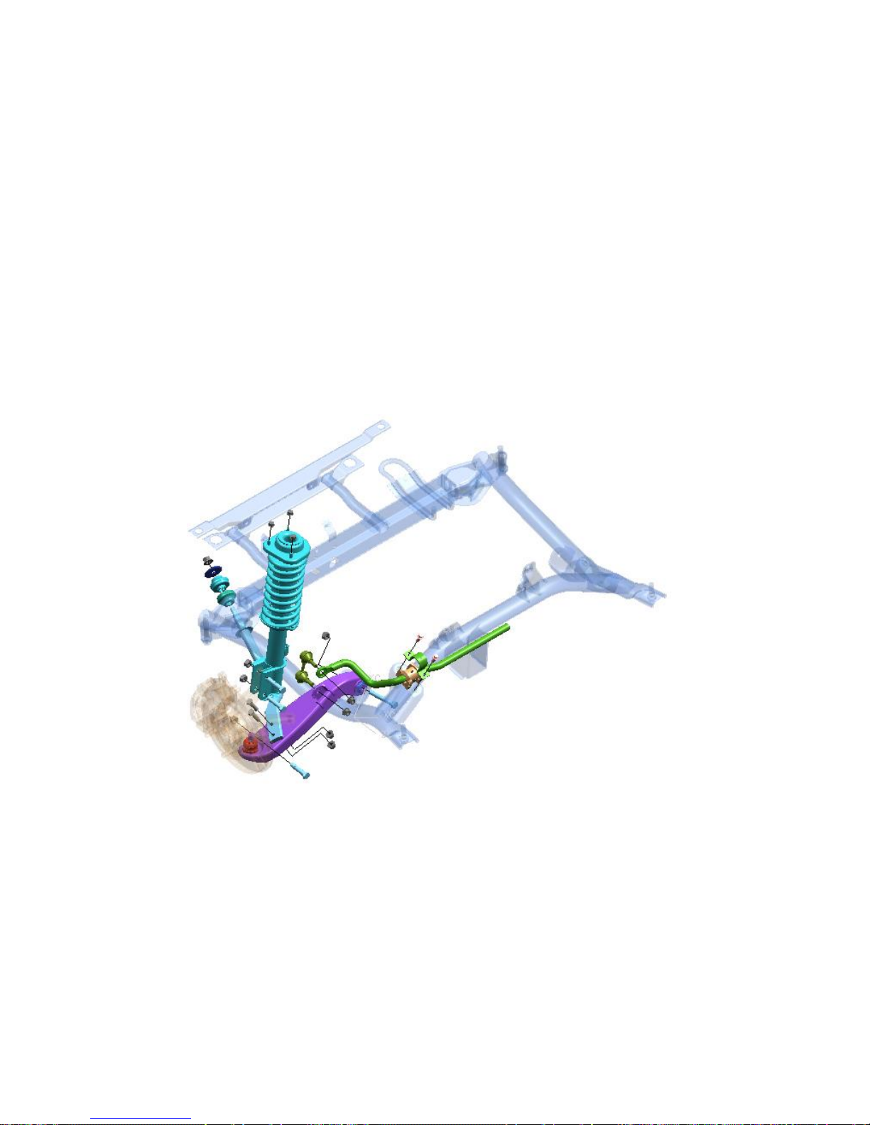
The front axle of Chery S21 model adopts the split steering drive axle, with MacPherson independent
suspension. The upper end of the suspension is connected with the vehicle body as the lower end is connected
with the secondary vehicle frame. The front Macpherson suspension undertakes the dual functions of driving
and steering. Subframe connects with vehicle body via elastic element, which improves diving stability and ride
comfort.
Structural diagram of Front Axle and Suspension System
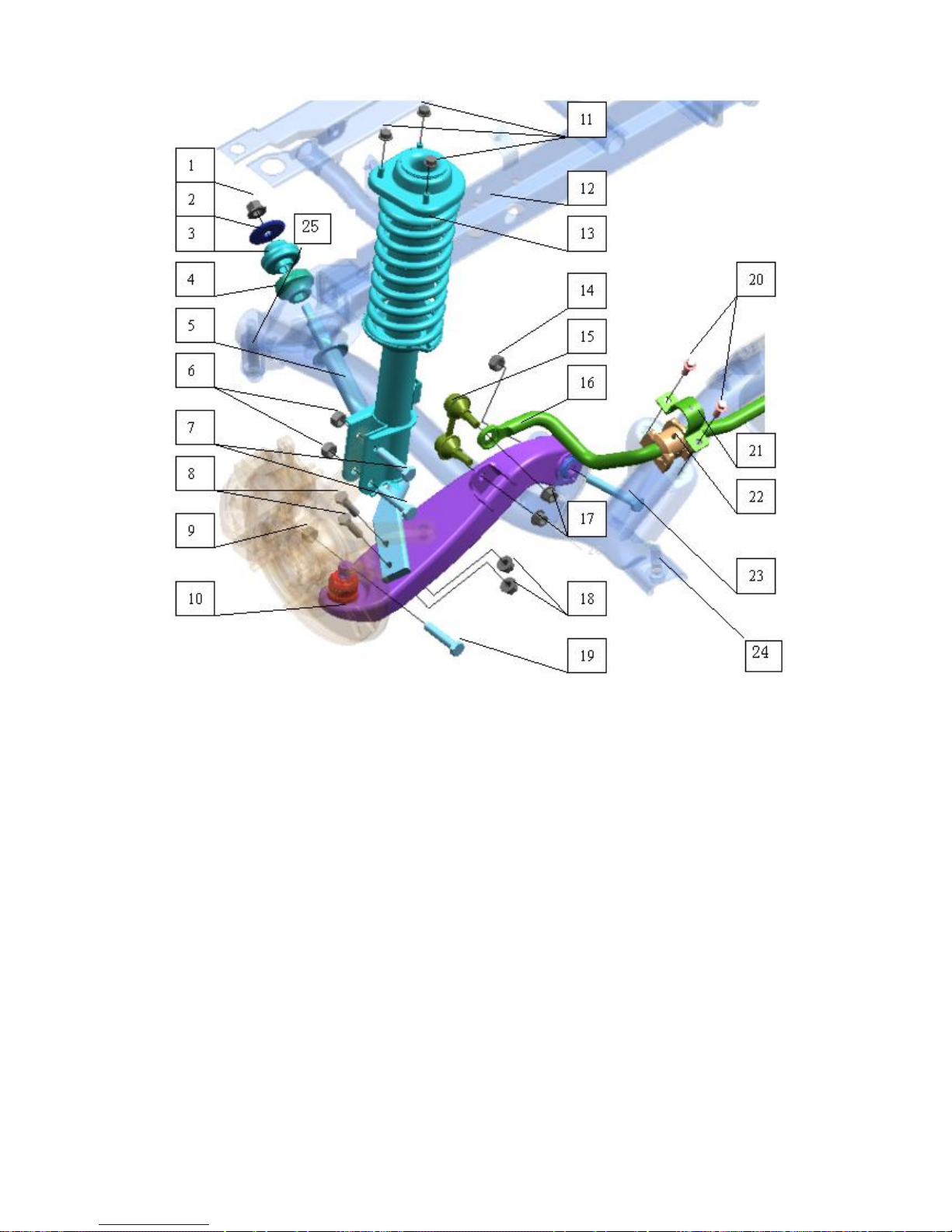
1 Nut 9 Nut 17 Nut
2 Gasket 10 Left control arm 18 Nut
3 Rubber gasket I 10 Right control arm 19 Bolt
4 Rubber gasket II
5 Left propelling rod weldment assembly 12 Secondary vehicle frame 21 Clamp
5 Right propelling rod weldment assembly 13 Front strut assy. 22 Rubber bush
6 Nut 14 Nut 23 Bolt
7 Bolt 15 Front connecting rod assy. 24 Bolt
8 Bolt 16 Front stabilizer bar 25 Bolt
Composition List for Front Axle and Suspension System
11 Nut 20 Bolt
2. Preparations
Tools: 8#, 15#, 18#, 19# socket; 10#, 13#, 15# wrench.
3. Notices
2.1 Please wear necessary labor protection supplies to avoid accidents.
2.2 When carry out maintenance and repair to chassis, please note that whether the safety lock of lifting
machine is locked.
2.3 When carry out removal/installation to shock absorber spring, prevent spring ejection from being injured.
2.4 It’s prohibited to conduct the welding and correction on the bearing components of the wheel suspension
and the guiding components of the wheels.
2.5 During the removal of the chassis component, renew the self-lock nuts and rusted nuts so as to guarantee the
safety.
4. Removal/Installation Procedure
4.1 Removal of shock absorber assembly
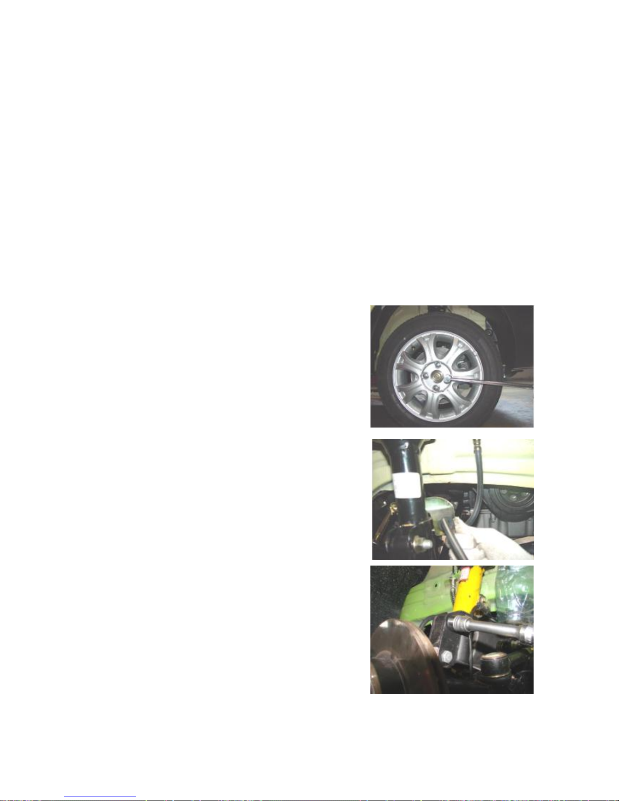
4.1.1 Remove the tire fixing nuts with 19# socket or vehicle attached
wrench to remove the tire (take left side for instance).
Torque: 110±10 Nm
4.1.2 Remove the ABS pipeline from the fixing seat with hand.
4.1.3 Remove the fixing bolts of steering joint and shock absorber
with 18# socket.
Torque: 110±10 Nm
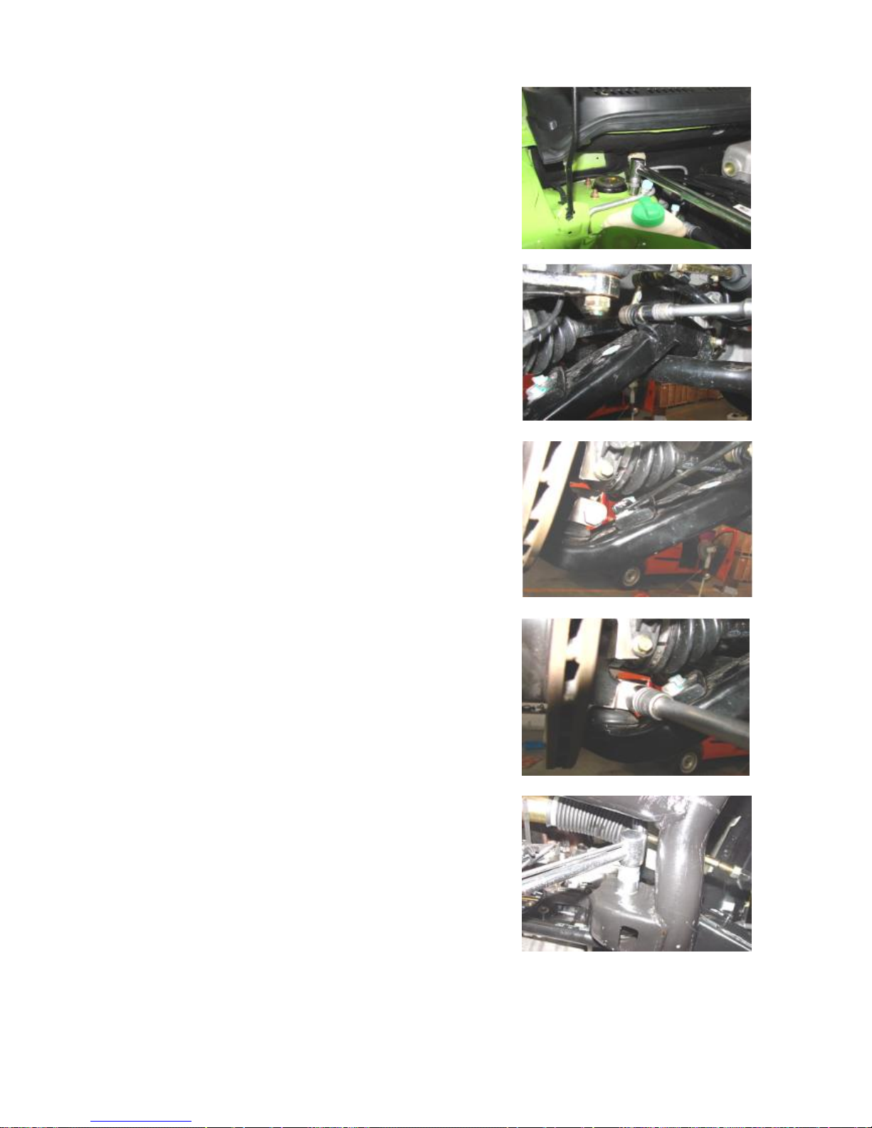
4.1.4 Remove the three fixing bolts of shock absorber assembly
from the vehicle frame with 13# socket.
Torque: 60±5 Nm
4.1.5 Remove the shock absorber assembly.
4.2 Removal of Control Arm Assembly
4.2.1 Remove the fixing bolts of front connecting rod assembly from
the control arm with 15# socket.
Torque: 100±10 Nm
4.2.2 Remove the connecting bolts of front propelling rod and
control arm with 15# wrench.
Torque: 75±5 Nm
4.2.3 Remove the ball joint fixing bolts from control arm and
steering universal joint with 18# socket and 18# ring wrench.
Torque: 100±10 Nm
4.2.4 Remove the connection bolts of control arm and front axle
with 18# socket to remove the control arm assembly.
Torque: 150±10 Nm
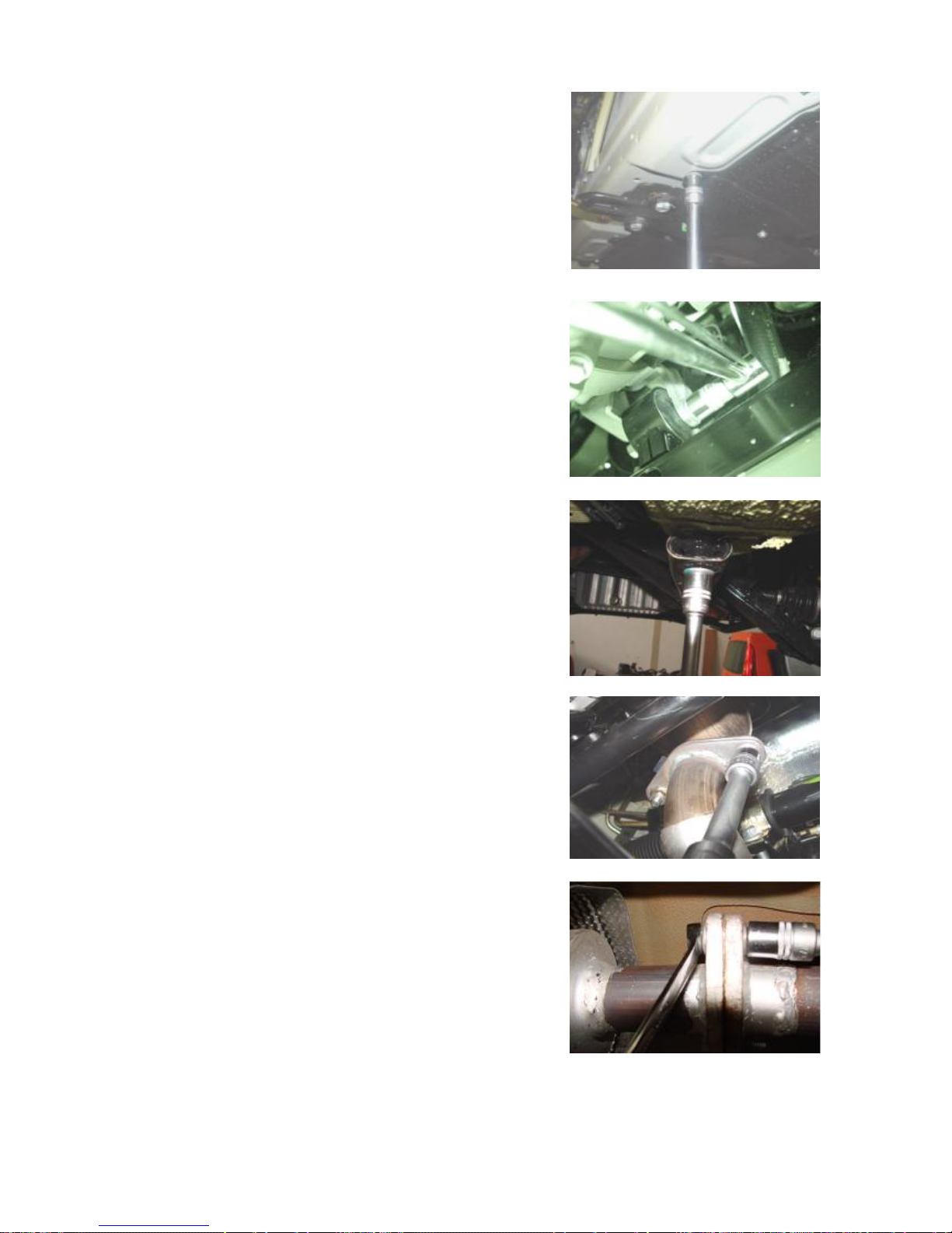
4.3 Removal of Front Axle Assembly
4.3.1 Remove the fixing bolts from the chassis mud guard to remove
the mud guard assembly.
Torque: 3±0.5 Nm
4.3.2 Remove the front bracket bolts of the transmission from the
secondary vehicle frame with 19# socket.
Torque: 110±10 Nm
4.3.3 Remove the rear bracket bolts of the transmission from the
secondary vehicle frame with 19# socket.
Torque: 110±10 Nm
4.3.4 Remove the two connecting bolts of front exhaust pipe with
15# socket.
Torque: 50±5 Nm
4.3.54 Remove the two connecting bolts of front exhaust pipe and
rear muffler with 15# socket.
Torque: 50±5 Nm
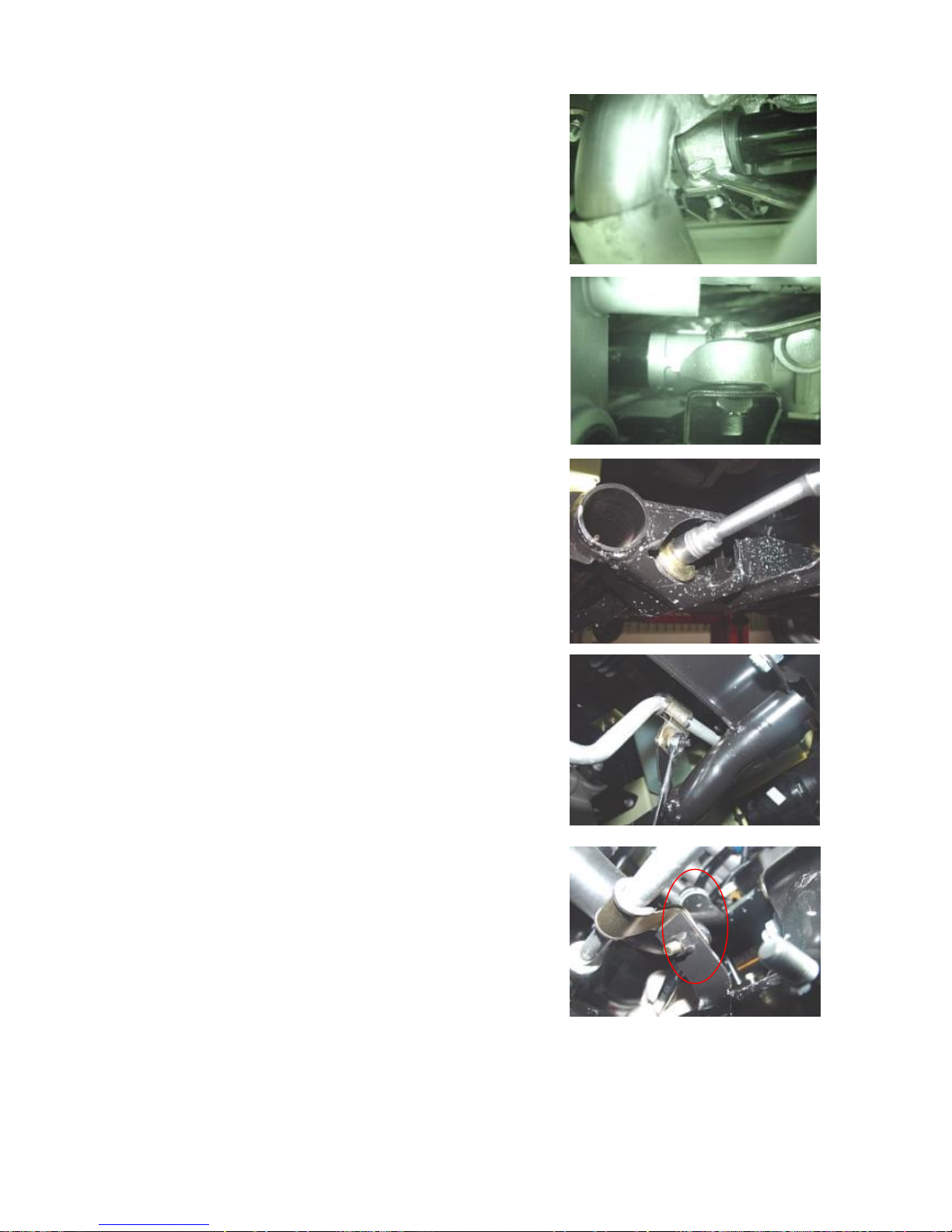
4.3.6 Remove the fixing bolts at the right side of the booster steering
gear with 13# wrench.
Torque: 75±5 Nm
4.3.7 Remove the fixing bolts at the left side of the booster steering
gear with 15# wrench.
Torque: 75±5 Nm
4.3.8 Remove the fixing bolts of propelling rod and secondary
vehicle frame with 19# socket.
Torque: 105±10 Nm
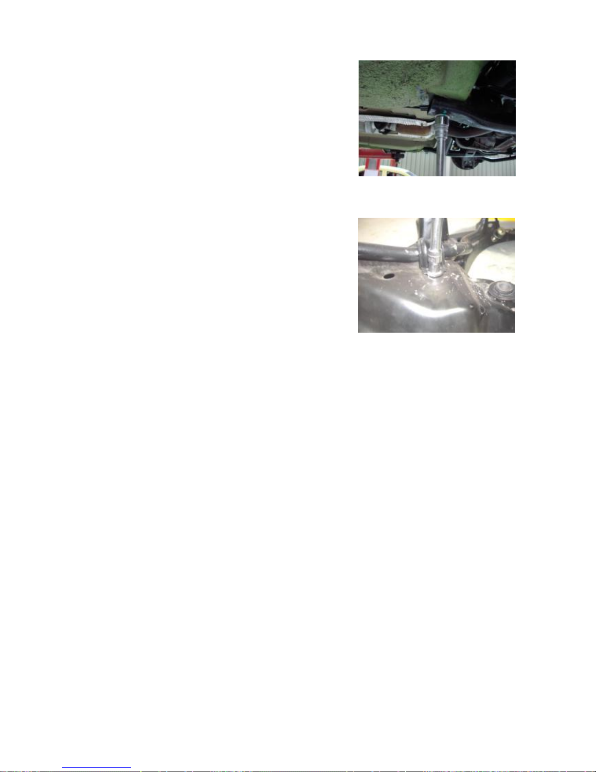
4.3.9 Remove the fixing bracket of the A/C pipeline from the
secondary vehicle frame with 10# wrench.
Torque: 25±2.5 Nm
4.3.10 Remove the fixing bracket of the condenser from the
secondary vehicle frame with 13# wrench.
Torque: 45±5 Nm
4.3.11 Remove the four connecting nuts of secondary vehicle frame
and vehicle body with 18# socket to remove the front axle assembly.
Torque: 150±10 Nm
4.3.12 Remove the fixing bolts and nuts from the rubber sleeve of
the stabilizer rod with 10# wrench.
Torque: 50±5 Nm
5. Installation Procedure
Refer to the removal procedures of front axle and front suspension.

II. Removal/Installation and Overhaul of Rear Axle and Suspension
1. System Structural Diagram
1 Rear trailing arm assembly 7 Rear shaft welding assembly 13 Nut
2 Bolt
3 Rear shock absorber assembly 9 Rear spring cushion 15 Bolt
4 Nut
5 Bolt
6 Bolt 12 Nut 18 Bolt
Structural diagram of Rear Axle and Suspension System
8 Cross stay assembly 14 Nut
10 Rear bumper block 16 Lock nut
11 Rear coil spring
17 Rear brake band drum assembly
2. Preparations
Tools: 11#, 13#, 15#, 16#, 16#, 19#, 30# socket, Slotted screwdriver,
priers.
3. Notices
3.1 Please wear necessary labor protection supplies to avoid
accidents.
3.2 Notice to lock the safety lock of the elevator during the repair of
the chassis.
3.3 When carry out removal/installation to shock absorber spring,
prevent spring ejection from being injured.
4. Removal/Installation Procedure
4.1 Removal of Shock Absorber Assembly and Shock Absorber
Spring.
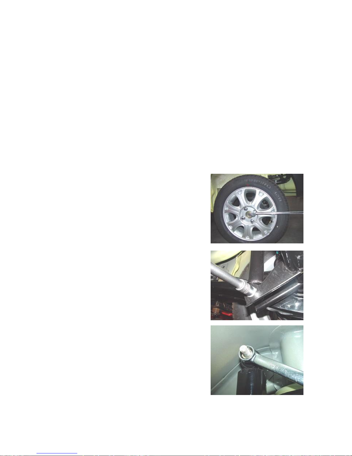
4.1.1 Remove the tire fixing nuts with 19# torque wrench or vehicle
attached wrench to remove the tire (take left side for instance).
Torque: 110±10 Nm
4.1.2 Remove the connecting bolts of shock absorber assembly and
rear axle with 18# socket.
Torque: 100±10 Nm
4.1.3 Remove the connecting bolts of shock absorber assembly and
vehicle body with 18# socket to remove the shock absorber
assembly.
Torque: 100±10 Nm
4.1.4 Pry out the rear coil spring with screwdriver.
4.1.5 Vibrate from side to side with force with hand to remove the
rear bumper block.
4.2 Cross Stay Assembly
4.2.1 Remove the connecting bolts of cross stay and left side of
vehicle body with 16# socket.
Torque: 100±10 Nm
4.2.2 Remove the connecting bolts of cross stay and right side of
vehicle body with 15# socket to remove the cross stay assembly.
Torque: 100±10 Nm
4.3 Rear Trailing Arm Assembly
4.3.1 Remove the connecting bolts from the rear side of rear axle
and trailing arm assembly with 13# socket.
Torque: 100±10 Nm
4.3.2 Remove the connecting bolts from the middle side of rear axle
and trailing arm assembly with 13# socket.
Torque: 100±10 Nm
4.3.3 Remove the connecting bolts of trailing arm and vehicle body
with 15# wrench to remove the rear trailing arm assembly.
Torque: 100±10 Nm
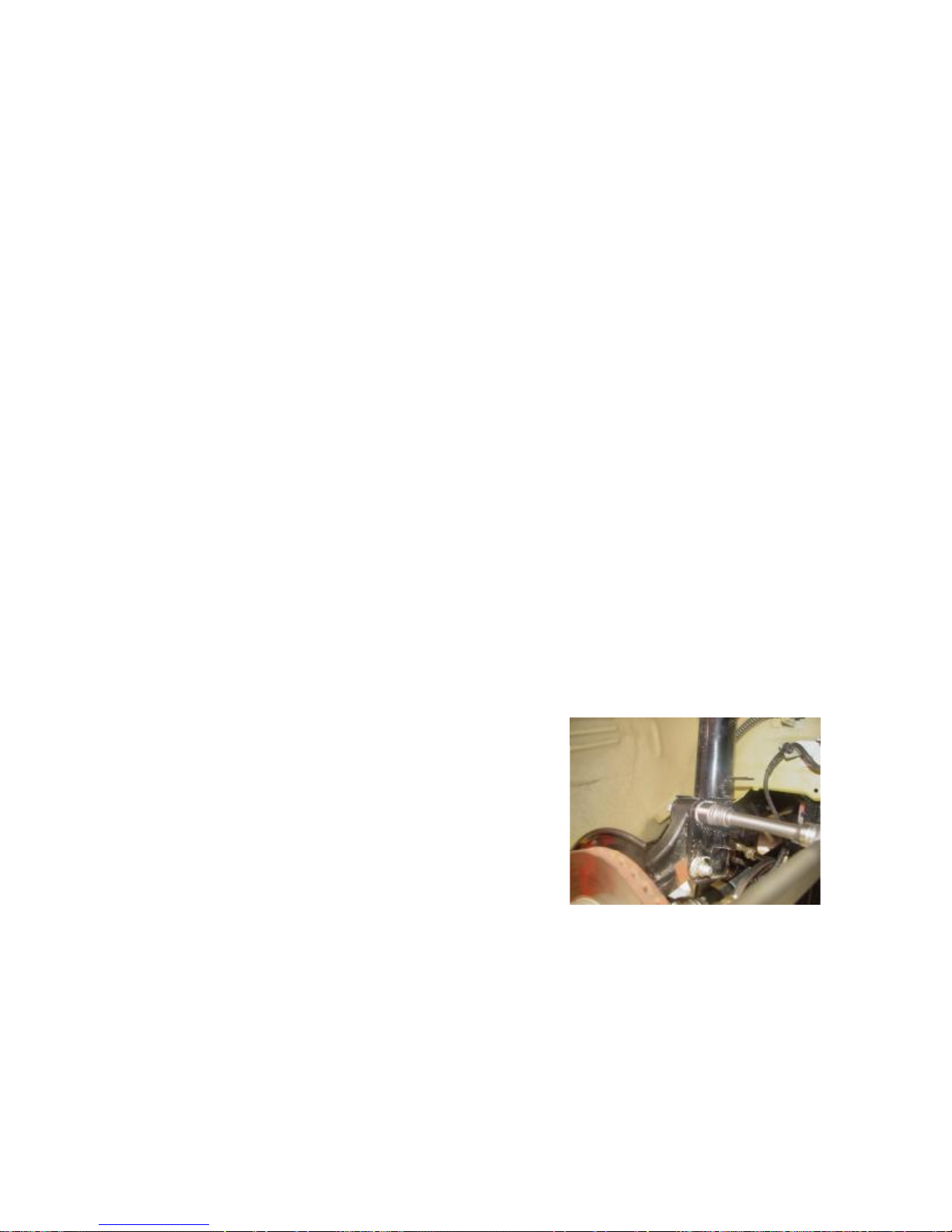
4.4. Removal of Rear Axle Assembly
4.4.1 Remove the connecting bolts of brake pipeline and rear axle
with 11# socket. Notice the storage of brake liquid.
Torque: 16±3 Nm
4.4.2 Remove the rear brake band drum assembly.
4.4.3 Remove the handbrake cable with priers.
4.4.4 Remove the lock nuts from the rear brake band drum assembly
with 30# socket to remove the rear brake band drum assembly.
Torque: 180±10 Nm
4.4.5 Remove the rear axle assembly.
5. Installation Procedure
The installation procedure is reverse to that of removal.
III. Adjustment of Four-Wheel Alignment
Please conduct the measurement and adjustment of parameters on
the four-wheel alignment instrument recommended by Chery Auto.
1. Adjustment of Front Wheel Toe-In
The toe-in can be adjusted by means of the optical testing
instrument or mechanical toe-in adjustment instrument.
1.1 Depending on the requirements of the testing instrument,
conduct the pre-adjustment preparations for the wheel alignment;
1.2 Loosen the lock nuts of right steering track rod and the spring
clips of protective sleeve. Based on the demands, rotate the toe-in
adjustment rod to adjust the length, till reach the specified value.
Toe-in value: 6′±6′
1.3 Tighten the lock nuts and install the spring clips of the
protective sleeve. Check if the lock nuts are properly tightened
and the protective sleeve is in right position;
Torque: 35±3 Nm
1.4 At the finish of toe-in adjustment of front wheels, check the
steering wheel for levelness. Otherwise, loosen the lock nuts of the
steering wheel, adjust the steering wheel to level position, and then
tighten the lock nuts of the steering wheel to the specified torque.
2. Adjustment of Front Wheel Camber Angle
2.1 Under normal conditions, it’s unnecessary to adjust the camber
angle after the assembling of independent suspension and wheel
steering joint. In case the wheel camber angle is out of the tolerance
scope due to other reasons, it may be calibrated by means of the
connecting bolts of independent suspension and steering joint.
Front wheel camber angle: 0.87°±50′
2.2 Before the calibration, check (visual observation) the driving
system components for damage and replace the damaged parts.
2.3 In case the front wheel camber angle is out of tolerance,
loosen the connecting bolts of front shock absorber and steering
joint and move the wheels for correction.
Caster Angle and Kingpin Inclination
The caster angle and the kingpin inclination are guaranteed by the
designed structure and are free of adjustment during use.
3. Adjustment of
 Loading...