

Page 1
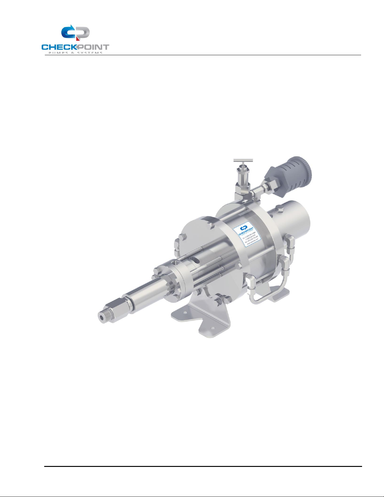
Series 6200 Pneumatic Chemical Injection Pump
Operating Manual
CP-MAN-PRD-6212 REV10 EFF. DATE: 07/23/2019 Page 1 of 13
Louisiana, US
Aberdeen, UK
Dubai, UAE
Ras Al Khaimah, UAE
21356 Marion Lane
Unit C2 Lombard Centre
Jebel Ali Free Zone | JAFZA 1 AB810
RAK Technology Park, Shed 2, Warehouses 7 & 8
Mandeville, LA 70471
Kirkhill Place, Kirkhill Industrial Estates
PO Box 262131
Al Hamra Industrial Zone
+1 (504) 340-0770
Dyce, Aberdeen, AB21 0GU Scotland
Dubai, United Arab Emirates
PO Box 54796
+44 (0) 1224 775205
+971 (04) 880-6278
Ras Al Khaimah, United Arab Emirates
+971 (07) 223-9961
Series 6200
Pneumatic Chemical Injection Pump
Operating Manual
Page 2

Series 6200 Pneumatic Chemical Injection Pump
Operating Manual
CP-MAN-PRD-6212 REV10 EFF. DATE: 07/23/2019 Page 2 of 13
TABLE OF CONTENTS
1. PUMP INSTALLATION 3
1.1 Process Design & Setup ............................................................................................................................. 3
1.2 Connecting The Chemical Supply .............................................................................................................. 5
1.3 Connecting The Supply Gas ....................................................................................................................... 7
2. GAS RECOVERY SYSTEMS - INSTALLATION 8
3. PUMP OPERATION 8
3.1 Setting The Pump Stroke Rate .................................................................................................................. 8
4. AIR/GAS CONSUMPTION 9
5. PUMP MAINTENANCE 10
5.1 Lubrication ................................................................................................................................................ 10
6. TROUBLESHOOTING 11
6.1 Pump runs, but chemical does not discharge at the correct rate ........................................................ 11
6.2 Pump does not stroke .............................................................................................................................. 11
6.3 Pump strokes erratically........................................................................................................................... 12
6.4 Chemical leakage from packing .............................................................................................................. 12
6.5 Other problems ......................................................................................................................................... 12
Page 3
Series 6200 Pneumatic Chemical Injection Pump
Operating Manual
CP-MAN-PRD-6212 REV10 EFF. DATE: 07/23/2019 Page 3 of 13
Congratulations! You have chosen the finest, most versatile chemical injection pump made; designed to exacting
specifications for long life, reliable performance, and low maintenance. To ensure proper operation and to maximize
the Series 6200’s durability, please read and follow this manual. Failure to correctly install and maintain the pump is
the primary cause of premature pump failure and voids the product warranty.
NOTE: This IOM applies to the CheckPoint 6212 Pneumatic Chemical Injection Pump, part number
P621277Q3.
NOTE: Important illustrations, graphs, and charts are located throughout this manual, with cutaway
drawings of the pump in the back.
1. PUMP INSTALLATION
1.1 Process Design & Setup
1.1.1 Before installation, please inspect the pump carefully for any possible in-transit damage. If the pump appears
damaged, call your authorized CheckPoint distributor or call CheckPoint customer service directly at (800) 847-7867
or (504) 340-0770 to confirm damaged condition. If we determine that damage has occurred in transit, you will need
to file a claim with the carrier.
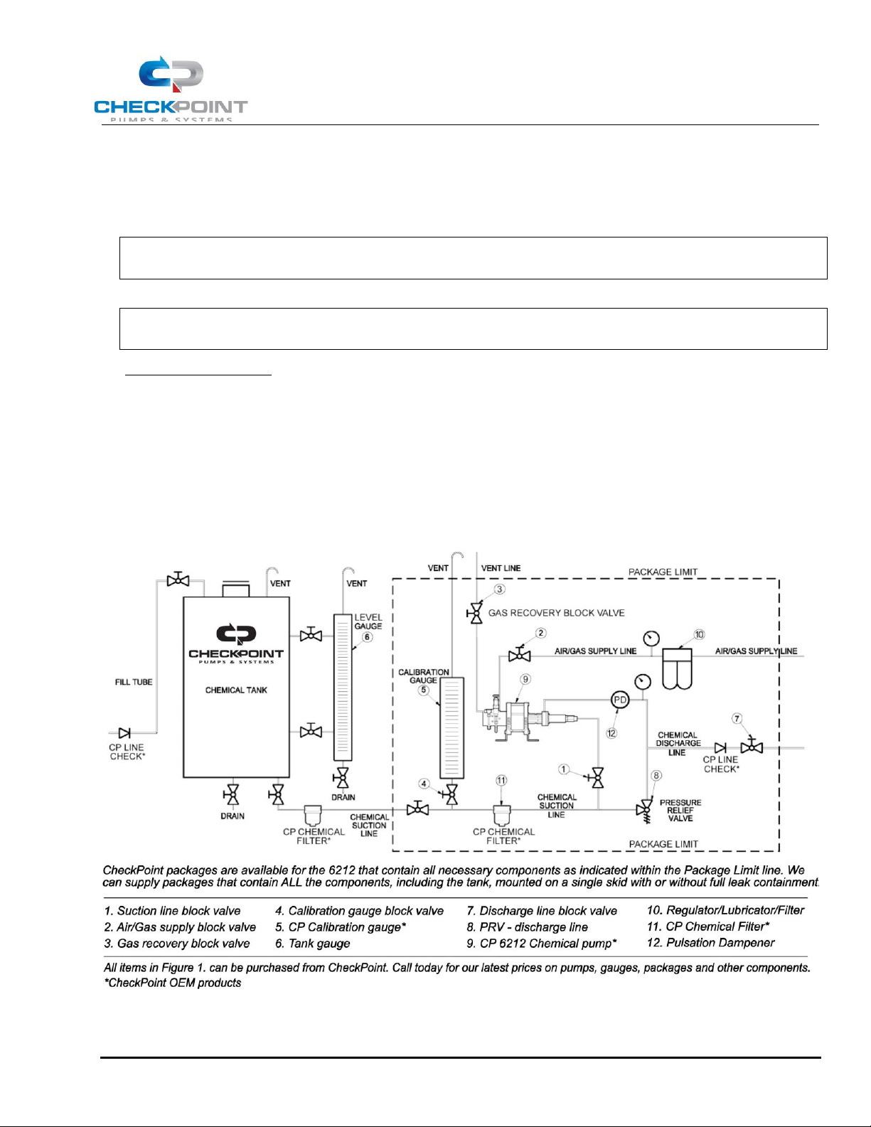
FIGURE 1: TYPICAL INSTALLATION SCHEMATIC
1.1.2 Referring to Figure 1 above, ensure that all necessary components are present in your injection system and
in good working order. All the components shown above are recommended by CheckPoint to maximize productivity
Page 4
Series 6200 Pneumatic Chemical Injection Pump
Operating Manual
CP-MAN-PRD-6212 REV10 EFF. DATE: 07/23/2019 Page 4 of 13
and life of the pump in typical field or plant use. CheckPoint is available to answer your process questions or to help
design and build a package system utilizing components appropriate for your application.
NOTE: In Figure 1, the secondary chemical filter, vent line, and pressure regulator are optional under
certain conditions but are highly recommended.
1.1.3 CheckPoint recommends horizontal mounting for the Series 6200 model pumps where possible. However, you may also mount the pump in other orientations, subject to the condition that the chemical head should be no higher than level with the motor.
CAUTION: If the pump chemical head (“wet end”) is above the motor, gravity and plunger action will
eventually pull chemical into the pneumatic motor, causing damage to the motor and
atomizing chemical into the surrounding air.
1.1.4 Either a suction-side calibration gauge or a discharge flow meter are the only means through which you can
accurately set the flow rate of the pump. Many variables, including temperature, chemical viscosity, supply air
pressure, etceteras, preclude the use of tables, graphs, or formulas to determine the speed of the pump. Also,
without a calibration gauge or flow meter, it cannot be determined if the pump is primed and functioning normally.
For instructions on the proper use of a suction-side calibration gauge, please read section 3.1.1 Setting Pump Speed
Using a Calibration Gauge on page 8 for more information. The proper placement of a calibration gauge (labeled
#5) is shown in Figure 1. CheckPoint offers a complete range of accurate and durable calibration gauges and
discharge-side flow meters suitable for 6212 pump service.
NOTE: It is necessary to attach a vent tube to the top of all calibration gauges, chemical tanks, and tank
level gauges. The height of the top of each vent tube should always be greater than the highest
possible liquid level in the system, and the tube should have means to prevent water entry, such as
a 180 degree bend.
1.1.5 The Series 6200 does not require flooded suction or positive chemical pressure to prime, and can therefore
be mounted above the chemical container. For a chemical with average viscosity, the pump will pull air out of the
chemical line and prime from up to twelve feet above the liquid level in the tank. This feature is dependent upon
proper adherence to all points made in Paragraph 1.1.6 below.
1.1.6 ALL COMPONENTS AND PIPEWORK BETWEEN THE CHEMICAL TANK AND THE SUCTION CHECK VALVE OF
THE PUMP MUST BE 100% BUBBLE-TIGHT AND FULLY COMPATIBLE WITH THE CHEMICAL AND WITH EACH OTHER.
FAILURE TO ADHERE STRICTLY TO THIS DIRECTIVE WILL LEAD TO LOSS OF PRIME AND DAMAGE TO THE PLUNGER
SEAL AND PLUNGER. SPECIFICALLY:
1.1.6.1 Any fitting or screw-on joint without Teflon™ tape or other acceptable sealant may allow air at atmospheric pressure to enter the suction tubing, even if no chemical leakage is visible.
1.1.6.2 Dissimilar metals in the suction side of the injection system may react with each other, creating gas
bubbles that will be carried into the pump head. All suction components, tubing, pipe, fittings, and valves must be
composed of similar metals. 316L SS, and Hastelloy C are the only metals CheckPoint uses in our packages for
suction side components. There are other acceptable choices; the key is that whatever metal is selected must be
used in the entire suction side of the system.
1.1.6.3 Incompatibility between the chemical and the components in the suction side of the injection system may
create gas bubbles that will be carried into the pump head. Some chemicals, for example, require Hastelloy™ or
PVC fittings and tubing, while other chemicals may only require 316 SS.
Page 5
Series 6200 Pneumatic Chemical Injection Pump
Operating Manual
CP-MAN-PRD-6212 REV10 EFF. DATE: 07/23/2019 Page 5 of 13
1.1.7 The pump may be mounted to a skid or other surface in a number of ways, however, clamping around the
outside of the pump can permanently affect the cylindricity of the air motor, voiding the product warranty. This
method also reduces accessibility during maintenance and troubleshooting and is therefore not recommended.
CheckPoint ships the 6212 with pre-drilled feet, and this is the recommended method for mounting the pump.
1.1.8 Always check to ensure that all process block valves (labeled as nos. 2, 3 & 7 in Figure 1) are closed prior to
disconnecting or re-installing any chemical injection pump. There should always be a block valve placed between a
properly installed pump and the process flow, the gas supply, the chemical supply, and the gas recovery outlet
(labeled #3). Conversely, while the pump is running, all such block valves should always be open.
1.1.9 The pump suction line should be sized appropriately to the flow rate to avoid cavitatation. A general rule of
thumb is to size the suction line such that instantaneous flow velocity through the line does not exceed 2 feet per
second at any point. For multiple pump installations, for extremely viscous chemicals, and for chemicals with low
vapor pressures, additional allowances may be needed. Contact CheckPoint or your authorized CheckPoint
distributor for design assistance.
1.1.10 TO AVOID OVER-PRESSURING CHEMICAL DISCHARGE LINES, CHECKPOINT REQUIRES PLACING A
PROPERLY TESTED AND CALIBRATED PRESSURE RELIEF VALVE BETWEEN THE DISCHARGE PORT OF THE PUMP AND
THE PROCESS FLOW. THE RELIEF VALVE DISCHARGE CAN BE RUN TO A TEE UPSTREAM OF THE PUMP’S CHEMICAL
SUCTION CHECK VALVE. FAILURE TO USE A PRV IS INHERENTLY UNSAFE AND MAY LEAD TO CATASTROPHIC
FAILURE OF PROCESS EQUIPMENT DUE TO EXCESSIVE PRESSURE. CHECKPOINT IS NOT RESPONSIBLE FOR ANY
DAMAGE CAUSED BY OVER-PRESSURIZED CHEMICAL. CheckPoint offers a range of pressure relief valves suitable
for use with the 6212 pump.
CAUTION: When using a pressure relief valve, the chemical tank MUST BE properly vented to
atmosphere to avoid the possibility of over-pressurizing the tank if the pressure relief valve
actuates.
1.1.11 Pulsation dampeners may be required in your installation depending on a variety of factors. Consult with CheckPoint if you have any concerns about pulsation.
1.2 Connecting The Chemical Supply
1.2.1 Clean suction lines and check chemical containers to ensure that they are free of all foreign matter, sand, sludge, or chemical buildup.
NOTE: Removing foreign debris from suction lines and chemical containers will substantially extend the
life of the packing and other components of the pump. Even a new chemical tank can contain
debris that can be carried into the pump and damage it.
Page 6
Series 6200 Pneumatic Chemical Injection Pump
Operating Manual
CP-MAN-PRD-6212 REV10 EFF. DATE: 07/23/2019 Page 6 of 13
NOTE: CheckPoint recommends using filtration to ensure a maximum particulate size of 140 microns.
Multiple stages of filtration should be considered, depending upon the initial cleanliness level of
the fluid media being pumped, to prevent cavitation and an increase in maintenance.
NOTE: If premature scoring of the pump plunger or early packing failure is observed during operation, a
likely cause is abrasive particles carried into the pump through the suction plumbing. Use of a presuction in-line chemical filter such as the CheckPoint Series FSTS and/or a ceramic or HastelloyTM
plunger is recommended if symptoms continue. Call CheckPoint for appropriate filter element
sizing criteria.
CAUTION: Substantial scoring of the plunger can lead to severe leakage of chemical into the
surrounding environment.
1.2.2 Connect the chemical suction line to the suction check valve on the pump head. (See illustrations in the Parts
List). The suction check valve is a male ¾" NPT. Care must be taken not to over-tighten NPT connections. For more
information regarding the procedure for properly making NPT connections, please refer to the CheckPoint NPT
connection procedure, available on request.
NOTE: Always apply Teflon™ tape or other appropriate thread sealant to the check valve threads prior to
attachment to prevent leakage.
NOTE: Never re-locate the suction check valve away from the chemical head. To operate properly, the
check valve must remain directly attached to the chemical head. (This may sound like common
sense, but it happens more often than you would think.)
1.2.3 Connect your discharge line to the pump discharge port. (See illustrations in the Parts List). The discharge
port is female 3/8" NPT. Note that there is no external discharge check valve on the 6212 pump, it is internal to the
chemical head. Care must be taken not to over-tighten NPT connections. For more information regarding the
procedure for properly making NPT connections, please refer to the CheckPoint NPT connection procedure,
available on request.
1.2.4 Open the process block valve, allowing the process pressure to reach the chemical head. Correct any leakage observed.
CAUTION: The 6212 pump chemical head is rated for a maximum working pressure of 10,000 PSIG. If
the discharge line is inadvertently blocked for any reason, the pump can generate pressures
in excess of 10,000 PSIG. A relief valve MUST be placed between the discharge port and the
process flow to prevent this condition. To predict the maximum pressure that can be
developed by your pump, use the formula: [supply air pressure] x [amplification ratio] =
[discharge pressure]. To find the amplification ratio for your pump, please see Figure 2 on
page 7.
NOTE: Always open the process block valve (shown as number 7 in Fig 1) prior to operating the pump.
Operating the pump with a closed block valve can generate enough pressure to rupture the
discharge line, damage process equipment and the chemical head itself, and reduce the life of the
pump.
Page 7
Series 6200 Pneumatic Chemical Injection Pump
Operating Manual
CP-MAN-PRD-6212 REV10 EFF. DATE: 07/23/2019 Page 7 of 13
1.3 Connecting The Supply Gas
1.3.1 Gas supply to the pump should be clean compressed air or natural gas at 50 PSIG minimum, 150 PSIG
maximum. “Clean” means free of abrasive dust, sand or other grit that could abrade the seals inside the pump. If
using natural gas, it must be free of most production enhancement chemicals and certain distillate products,
especially salts and certain aromatics that can attack the motor end seals and/or the metallic elements in the air
motor.
NOTE: In warmer climates, it is not necessary to remove water and certain other liquids from the supply
gas. The pump will not stall no matter how much liquid reaches the air/gas inlet. However, large
slugs of liquid will slow the pump action substantially. In cold climates, there is high risk of liquids
freezing inside the motor. Also, certain chemicals will degrade seals in the motor, so the supply gas
must be specified as part of the ordering process so that CheckPoint can supply the correct seals
for your application and/or advise appropriate gas conditioning equipment. CheckPoint offers a
range of gas regulator/filter/lubricators ideal for 6212 pump applications.
CAUTION: Always use a gas pressure regulator if the possibility of supply pressures in excess of 150
psig exists. Allowing higher gas pressures to enter through the air/gas inlet will most
probably result in damage to the motor seals.
1.3.2 Liquids may also be used as a driver fluid, but pump speed will vary widely with the liquid viscosity. Call CheckPoint for performance data for the liquid you intend to use.
1.3.3 Blow the supply gas line clean to remove all foreign matter and debris. NOTE: Take care to prevent debris in the supply gas line from entering the main spool housing and
switching valves, where it could accelerate seal wear and damage the main switching valve
components.
NOTE: In situations where sand, dirt, and other particulate matter may be carried in with the supply gas, a
filter and/or a scrubber is recommended. CheckPoint can supply gas conditioning equipment
suitable for your application.
1.3.4 Connect the supply gas line to the 1/2" Female NPT connection on the housing. To ensure positive injection,
the supply gas pressure should be a minimum of 50 PSIG and a maximum of 150 PSIG, set according to the following
formula:
REQUIRED GAS INLET PRESSURE =
[DISCHARGE PRESSURE]
X 1.3
[AMPLIFICATION RATIO]
1.3.5 Faster pump speeds can be obtained by increasing the gas inlet pressure from the minimum required by the
formula above.
NOTE: To find the Amplification Ratio for your pump, please see Figure 2 below.
NOTE: If the above formula yields a result of < 50 PSIG, use 50 PSIG as your supply pressure.
FIGURE 2: AMPLIFICATION RATIO TABLE, 6212
PLUNGER DIAMETER (IN)
AMPLIFICATION RATIO
Page 8
Series 6200 Pneumatic Chemical Injection Pump
Operating Manual
CP-MAN-PRD-6212 REV10 EFF. DATE: 07/23/2019 Page 8 of 13
0.750
64
2. GAS RECOVERY SYSTEMS - INSTALLATION
2.1.1 The exhaust gas can be exhausted directly to atmosphere, or can be recovered to a lower pressure gas system.
If vented directly to atmosphere, CheckPoint supplies the pump with a muffler to reduce exhaust noise.
2.1.2 If recovering the exhaust gas, connect the gas recovery line from the process to the open 3/8” tubing
connector on the pump. The pressure in the recovery line (“recovery pressure”) must be lower than the supply
pressure. To calculate the recovery pressure given your supply pressure in PSIG, use the following formula:
RECOVERY PRESSURE = SUPPLY PRESSURE -
[DISCHARGE PRESSURE]
- 30 PSIG
[AMPLIFICATION RATIO]
2.1.3
For gas recovery systems, the maximum recovery pressure, based on a supply pressure of 150 PSIG (the
maximum allowable supply pressure) is given by:
MAXIMUM RECOVERY PRESSURE = 120 PSIG -
[DISCHARGE PRESSURE]
[AMPLIFICATION RATIO]
2.1.4 For more information on how to set up a recovery system for your 6200 pump, please contact CheckPoint or
an authorized distributor.
3. PUMP OPERATION
3.1 Setting The Pump Stroke Rate
3.1.1 Setting Pump Speed Using a Calibration Gauge
The following directions are for setting the pump speed using a calibration gauge. There are a variety of calibration
gauges available, including a complete line of appropriately-sized CheckPoint gauges for every CheckPoint pump.
To ensure that your pump is working as it should and that chemical is being delivered at the rate you need, it is
important to use a calibration gauge or a discharge-side flow meter.
3.1.1.1 Most calibration gauges are designed to read properly when one full minute of pumping has taken place.
However, if the liquid level drops too fast to allow for a full minute, shorter periods are acceptable. Try to size the
gauge so that at least a 30 second test can be made, however, or a loss of accuracy will result.
3.1.1.2 Proper gauge placement and plumbing is important. Please refer to Figure 1 for appropriate valving and
placement, and for reference numbers as used in this section. The calibration gauge is labeled as number 5.
3.1.1.3 With the pump either running or stopped, open the Gauge Fill Valve (shown as #4 in Figure 1). The gauge
should begin to fill. Continue filling until the chemical level is at or near the top markings on the gauge, then close
the Gauge Fill Valve.
3.1.1.4 Now ensure that the CheckPoint pump is running. Take note of the level of chemical in the gauge using
the appropriate scale for the volume units you want to measure the pump’s output in. Usually the gauge will show
liters on one scale and quarts or gallons on the other. It is best to write down the number so that you can
calculate flow accurately.
3.1.1.5 Open the Gauge Fill Valve (#4), and simultaneously close the Chemical Supply Valve (shown as #1 in
Figure 1). This isolates the pump and gauge so that the pump is being supplied chemical directly from the gauge.
Page 9
Series 6200 Pneumatic Chemical Injection Pump
Operating Manual
CP-MAN-PRD-6212 REV10 EFF. DATE: 07/23/2019 Page 9 of 13
3.1.1.6 The level in the gauge should begin to fall. (If it does not, or if the level seems to go down and then back
up with each stroke, refer to troubleshooting in Section 5.1 on page 11). When the liquid level in the gauge gets
near the bottom of the gauge, or when one minute has expired (whichever comes first), stop timing, note the
ending level on the gauge, and reopen the Chemical Supply Valve.
3.1.1.7 Write down the amount of time in seconds and the final gauge reading, then close the Gauge Fill Valve. NOTE: Failure to reopen the Chemical Supply Valve will result in the pump quickly depleting the
remaining chemical in the gauge and running on air, necessitating pump re-priming.
NOTE: In cases where the chemical flow rate is extremely low, you may need to time for longer than one
minute to allow an adequate amount of chemical to move out of the gauge.
3.1.1.8 The pumping volume (in the units specified on the gauge scale) will be given by the following equation:
PUMPING VOLUME =
[END READING] – [BEGINNING READING]
X 60
[DURATION OF READING IN SECONDS]
NOTE: To ensure accurate stroke rate measurement, allow sufficient measurement duration. Where
possible, allow at least thirty seconds of gauge drawdown.
NOTE: At extremely slow stroke rates, only a small turn of the speed control valve is required to alter the
stroke rate, so if readjusting the rate of the pump, it is helpful to turn the valve only a small
increment (a couple of angular degrees) at a time.
FIGURE 3: VOLUME FACTOR TABLE, SERIES 6200
PLUNGER DIAMETER (IN)
VOLUME FACTOR
0.750
0.869
FIGURE 4: GENERAL CONVERSION TABLE
TO CONVERT:
TO:
MULTIPLY BY:
GALLONS
QUARTS
4.00
LITERS
QUARTS
1.058
CUBIC INCHES
QUARTS
0.0173
MINUTES
DAYS
0.000694
4. AIR/GAS CONSUMPTION
If emissions are a concern, refer to Section 2 for details on how to use the gas recovery feature of your CheckPoint
pump.
Use the following equation along with the appropriate gas consumption factor from Figure 5 to calculate air/gas
consumption.
Gas Consumption [SCFM] @ 68F = Chemical Flow Rate [GPH] * Gas Supply Pressure [PSIA] * English Gas
Consumption Factor
Page 10
Series 6200 Pneumatic Chemical Injection Pump
Operating Manual
CP-MAN-PRD-6212 REV10 EFF. DATE: 07/23/2019 Page 10 of 13
Gas Consumption [Nm3/Hr] @ 0C = Chemical Flow Rate [LPH] * Gas Supply Pressure [BARA] * SI Gas
Consumption Factor
NOTE: Gas supply pressure value must be absolute pressure, not gauge pressure (Absolute pressure =
gauge pressure + atmospheric pressure). For reference, the Earth's atmospheric pressure at sea level
is approximately 1 atm or 14.696 psi or 1.0133 bar.
NOTE: This is a theoretical consumption rate that will vary depending on gas density and other actual field
conditions. Air/Gas consumption can be minimized by using the minimum supply pressure required
to achieve the target application. Please contact CheckPoint for assistance estimating optimal supply
pressure and associated consumption rate for a particular application.
FIGURE 5: GAS CONSUMPTION FACTORS
GAS CONSUMPTION FACTOR
PUMP
SERIES
PLUNGER
DIAMETER
[IN]
ENGLISH
SCFM
@ 68F
SI METRIC
NM3/HR
@ 0C
6212
3/4
0.0123
1.0860
5. PUMP MAINTENANCE
The CheckPoint Series 6200 is designed to provide trouble-free operation for many years with little adjustment,
lubrication, or other routine maintenance. However, like any other device, proper maintenance can extend the life
of the product. This can include periodic cleaning of the gas and chemical inlets, and lubrication.
5.1 Lubrication
The CheckPoint Series 6200 motor was designed to run under “stone-dry” internal conditions in the motor end.
However, regular lubrication will maximize the life of the pump and thus add value to your investment. In addition
to minimizing friction within the pump, lubrication flushes out foreign debris, further reducing wear and tear on the
mechanism.
5.1.1 Periodic Lubrication To lubricate the pump periodically, block off and then disconnect the air/gas supply
line by unscrewing the fitting at the pump air/gas inlet. Introduce a light silicone-based lubricant or multigrade
motor oil into the air/gas inlet. Reconnect the air/gas supply line and reintroduce gas pressure. Lubricant will
become evenly distributed throughout the motor end of the pump within a few cycles.
5.1.2 Continuous Lubrication Lubricator bottles can be placed anywhere in the gas supply line prior to the pump’s
air/gas inlet. Set the lubricator rate as low as possible, one to two drops per minute, unless cold conditions dictate
more in order to prevent freezing of the gas supply. CheckPoint offers both a small and a large in-line lubricator;
call CheckPoint or your authorized CheckPoint distributor for details.
Page 11
Series 6200 Pneumatic Chemical Injection Pump
Operating Manual
CP-MAN-PRD-6212 REV10 EFF. DATE: 07/23/2019 Page 11 of 13
5.1.3 Recommended Lubrication Type A light hydraulic oil bearing the designation ISO 3448 viscosity no. 20-32
should be used. If atmospheric or other supply air/gas conditions present exhaust freezing issues, an antifreeze type
lubricant such as Kilfrost may be used.
6. TROUBLESHOOTING
6.1 Pump runs, but chemical does not discharge at the correct rate
6.1.1 Suction check valve may be clogged with debris To flush, open speed control valve fully, allow pump to
cycle at this maximum rate for at least 60 seconds, then return to the original setting. If no improvement is noted
after three repetitions, remove the suction check valve from body of pump, blow out with air or water pressure, or
rebuild if necessary, and reinstall.
NOTE: CheckPoint FailSafe
TM
check valves do not need replacement when they do not check properly. A
simple rebuild kit is available to replace the O-rings, which should correct all but the most severe
check problems. If corrosion of the valve seat, retainer and/or poppet is apparent, a different type
of check valve material is indicated.
NOTE: Always replace Teflon
TM
tape or other appropriate thread sealant on check valve threads during
reinstallation to avoid chemical leakage and/or air getting into the chemical head.
6.1.2 Pump may have lost prime/become “air locked” Check to ensure that there are no leaks in any process
lines, particularly upstream of the pump in the chemical suction lines. If the pump is getting any air through the
suction side, the pump will possibly lose prime. Please carefully read section 1.1.6 and its subparagraphs for more
details. A common source of air in the supply is the block valve ahead of the suction check. Check this valve to make
sure the stem packing is tight and that the materials of construction are compatible with the chemcial being
pumped. Check also that the pump’s packing is not leaking. Finally, on pumps supplying chemical into gas lines, it
is possible that the discharge port may be leaking, allowing gas under pressure to “back into” the chemical head.
6.1.3 Check valves may have been re-located away from the chemical head of the pump The checks must stay directly attached to the head in order to facilitate chemical movement.
6.1.4 Chemical may be obstructed from entering the pump Plumbing upstream of the chemical head may have
blockage preventing chemical from getting to the suction check valve. A common example is an in-line chemical
filter becoming clogged with debris. Solution is to clean out suction plumbing and clean or replace chemical filter.
6.1.5 Calibration gauge may be reading incorrectly due to clogged air vent If the calibration gauge is not
reading correctly, the user may be fooled into thinking the chemical is not getting into the process. Check for an
obstruction in the gauge or in the air vent atop the gauge.
6.2 Pump does not stroke
6.2.1 Pump speed control valve may not be turned on Open the speed control valve fully (counterclockwise) until pump actuates. Then set desired stroke rate as described in Section 3.1.2.
6.2.2 Air/Gas supply pressure may be too low to overcome the chemical discharge pressure In many cases, a
faulty pressure gauge or regulator is at fault. See Section 1.3.4 on page 7 to determine the minimum supply pressure
for your discharge pressure.
6.2.3 Gas recovery pressure is too high relative to gas supply pressure (Gas Recovery applications only) In
pumps where the exhaust gas is being recovered, the pump not only has to overcome the chemical discharge
Page 12

Series 6200 Pneumatic Chemical Injection Pump
Operating Manual
CP-MAN-PRD-6212 REV10 EFF. DATE: 07/23/2019 Page 12 of 13
pressure but also the gas recovery pressure. Refer to Section 2.1.1 on page 8 to determine the appropriate recovery
pressure.
6.2.4 Pump switching valve may be clogged or “gummed-up” with paraffin or trash Disconnect air/gas supply,
then pour any type of oil or solvent into the pump air/gas inlet. Re-connect air/gas supply and open speed control
valve. Repeat two to three times if necessary. When pump is running normally, reset pump stroking rate as described
in Section 3.1.2.
6.2.5 Spool may be swollen Occasionally, certain types of chemicals that are introduced into the motor through
the air/gas inlet may be absorbed by the standard spool material, causing it to swell. If, after removal of the housing
with the spool still inside, the spool will not move within the housing, call CheckPoint to order a replacement spool
made of a different material.
6.2.6 After a repair, alignment screw may have been incorrectly reinstalled If care is not taken to replace the
alignment screw finger tight prior to tightening by wrench, it may be that it has been screwed into the plastic spool
rather than into the alignment slot in the spool. Normally this can be corrected by removal of the alignment screw
and replacement after properly repositioning the clock position of the spool inside its housing.
6.2.7 Seals may be worn in the motor If the pump has been in service for some time, the motor seals may have
worn to the point where the pump can no longer switch. If air leakage is constant during stall, worn or damaged
seals are indicated. Performing an overhaul on the motor and replacing all seals is required.
6.3 Pump strokes erratically
6.3.1 Supply pressure may be fluctuating Check supply pressure with an accurate pressure gauge to ensure
constant supply pressure. If fluctuations are observed, replace gas pressure regulator, or, if none exists, add a
pressure regulator ahead of the air/gas inlet.
6.4 Chemical leakage from packing
6.4.1 Packing may be worn However, prior to replacing the packing, it is important to determine if wear is premature. Common causes of prematurely worn packing are:
6.4.1.1 Chemical may be attacking packing elastomer material The packing will appear swollen or badly
damaged once removed from the packing gland if it is being attacked by the chemical. Contact CheckPoint or
your authorized CheckPoint distributor. If the chemical has recently been changed or if the pump has just been
placed in service, there is a good chance that new packing materials are needed to do the job.
6.4.1.2 Chemical may be attacking plunger material The plunger will be severely worn, pitted, or corroded when inspected.
6.4.1.3 Chemical may have abrasives suspended in it The plunger will appear scored and the packing will appear severely worn if trash in the chemical is indicated. CheckPoint offers high performance chemical filters appropriate for 6212 applications.
6.5 Other problems
If you are experiencing an operating problem not listed above, or if none of the above troubleshooting actions
solves your operating problem, please contact your authorized CheckPoint distributor, or call CheckPoint directly at
(800) 847-PUMP or (504) 340-0770, to determine appropriate next steps. Once CheckPoint has had the opportunity
to help you troubleshoot your problem, please keep in mind the following regarding repairs:
6.5.1 CheckPoint offers exchange programs to keep you in service We will ship you a rebuilt pump, which you
will be able to install prior to sending us your existing pump. When we do receive your pump, we will tear it down,
Page 13

Series 6200 Pneumatic Chemical Injection Pump
Operating Manual
CP-MAN-PRD-6212 REV10 EFF. DATE: 07/23/2019 Page 13 of 13
rebuild it, and report back to you any problems we uncovered. We offer a fixed-price exchange plan, an actual-cost
plan, and a consigned exchange plan that allows you to stock rebuilt pumps and be charged only when you use
them. Please contact CheckPoint to learn more about this unique service.
6.5.2 Nothing beats factory-direct repairs Although the Series 6200 has been designed to be easy to operate
and to repair, the best way to ensure continued reliable service is to have your pump repaired at the factory. This is
the only way to ensure you always get the quality and reliability you invested in when you purchased the product.
6.5.3 Remember that after you repair your CheckPoint pump, it should perform as well as it did when it was new If it doesn’t, call us to determine what can be done to restore the pump to “like-new” performance.
6.5.4 Training sessions are available Please call us to set one up.
 Loading...