

Page 1

– 1 –
TABLE OF CONTENTS
1.0 Introduction . . . . . . . . . . . . . . . . . . . . . . . . . . . . . . . . . . . . . . . . . . . . . . . . . . . . 04
1.1 Standard Features
1.2 Accessories Included
2.0 Overview . . . . . . . . . . . . . . . . . . . . . . . . . . . . . . . . . . . . . . . . . . . . . . . . . . . . . 05
2.1 Main Unit
2.2 LCD Display
3.0 Setup . . . . . . . . . . . . . . . . . . . . . . . . . . . . . . . . . . . . . . . . . . . . . . . . . . . . . . 07
3.1 Battery management
3.2 Using Measurement Accessories
3.3 Using The Hanger
3.4 Using The Tracking Function
4.0 Function Modes . . . . . . . . . . . . . . . . . . . . . . . . . . . . . . . . . . . . . . . . . . . . . . . . . 09
4.1 Measurment Polarity
4.2 Display Update (f02)
4.3 Auto Power Off (f03)
4.4 Baud Rate (f04)
4.5 Response Time (05)
4.6 External Output (f06)
5.0 Reversing The Display . . . . . . . . . . . . . . . . . . . . . . . . . . . . . . . . . . . . . . . . . . . 12
6.0 Measuring Modes . . . . . . . . . . . . . . . . . . . . . . . . . . . . . . . . . . . . . . . . . . . . . . . 13
6.1 Standard Measuring Mode
6.2 Peak Measuring Mode
6.3 Changing Display Units
6.4 Tare
7.0 Comparator . . . . . . . . . . . . . . . . . . . . . . . . . . . . . . . . . . . . . . . . . . . . . . . . . . . . 15
7.1 Memory Setting Mode
7.2 Setting HI Limits
7.3 Settig LO Limits
7.4 Comparator Display
7.5 Comparator Output
8.0 Setting Memory Mode / Recording Data . . . . . . . . . . . . . . . . . . . . . . . . . . . . . 17
8.1 Retting The Memory Mode
8.2 Recording Memory Data
9.0 Reviewing Memory Data . . . . . . . . . . . . . . . . . . . . . . . . . . . . . . . . . . . . . . . . . 21
9.1 Continuous Mode Memory
9.2 Single Memory Mode
10.0 Clearing The Memory . . . . . . . . . . . . . . . . . . . . . . . . . . . . . . . . . . . . . . . . . . . . 26
10.1 Clearing The Last Record
10.2 Clearing All Memory
10.3 No Recorded Data
11.0 USB Communications. . . . . . . . . . . . . . . . . . . . . . . . . . . . . . . . . . . . . . . . . . . . 27
11.1 USB and Battery Life
0
– 36–
NOTES
Page 2

– 2–
12.0 External Data Port . . . . . . . . . . . . . . . . . . . . . . . . . . . . . . . . . . . . . . . . . . . . . . . 28
12.1 Pin Assignment
12.2 RS-232C Output
12.3 RS-232C Communications Commands
12.4 Connection Between FGV and Host
12.5 Analog Output
12.6 Overload / Comparator Output
13.0 Troubleshooting / Technical Questions . . . . . . . . . . . . . . . . . . . . . . . . . . . . . . . 32
14.0 Specifications . . . . . . . . . . . . . . . . . . . . . . . . . . . . . . . . . . . . . . . . . . . . . . . . . . 33
15.0 Dimensional Drawings . . . . . . . . . . . . . . . . . . . . . . . . . . . . . . . . . . . . . . . . . . . 34
16.0 Warranty . . . . . . . . . . . . . . . . . . . . . . . . . . . . . . . . . . . . . . . . . . . . . . . . . . . . . . 35
– 35–
16.0 WARRANTY
ELECTROMATIC Equipment Co., Inc. (ELECTROMATIC) warrants to the
original purchaser that this product is of merchantable quality and confirms
in kind and quality with the descriptions and specifications thereof. Product
failure or malfunction arising out of any defect in workmanship or material in the
product existing at the time of delivery thereof which manifests itself within one
year from the sale of such product, shall be remedied by repair or replacement of
such product, at ELECTROMATIC’s option, except where unauthorized repair,
disassembly, tampering, abuse or misapplication has taken place, as determined
by ELECTROMATIC. All returns for warranty or non-warranty repairs and/or
replacement must be authorized by ELECTROMATIC, in advance, with all
repacking and shipping expenses to the address below to be borne by the
purchaser.
THE FOREGOING WARRANTY IS IN LIEU OF ALL OTHER WARRANTIES,
EXPRESSED OR IMPLIED, INCLUDING BUT NOT LIMITED TO, THE
WARRANTY OF MERCHANTABILITY AND FITNESS FOR ANY
PARTICULAR PURPOSE OR APPLICATION. ELECTROMATIC SHALL NOT
BE RESPONSIBLE NOR LIABLE FOR ANY CONSEQUENTIAL DAMAGE,
OF ANY KIND OR NATURE, RESULTING FROM THE USE OF SUPPLIED
EQUIPMENT, WHETHER SUCH DAMAGE OCCURS OR IS DISCOVERED
BEFORE, UPON OR AFTER REPLACEMENT OR REPAIR, AND WHETHER
OR NOT SUCH DAMAGE IS CAUSED BY MANUFACTURER’S OR
SUPPLIER’S NEGLIGENCE WITHIN ONE YEAR FROM INVOICE DATE.
Some State jurisdictions or States do not allow the exclusion or limitation of
incidental or consequential damages, so the above limitation may not apply to
you. The duration of any implied warranty, including, without limitation, fitness
for any particular purpose and merchantability with respect to this product, is
limited to the duration of the foregoing warranty. Some states do not allow
limitations on how long an implied warranty lasts but, not withstanding, this
warranty, in the absence of such limitations, shall extend for one year from the
date of invoice.
ELECTROMATIC Equipment Co., Inc.
600 Oakland Ave. Cedarhurst, NY 11516—USA
Tel: 1-800-645-4330/ Tel: 516-295-4300/ Fax: 516-295-4399
Every precaution has been taken in the preparation of this manual. Electromatic
Equipment Co., Inc., assumes no responsibility for errors or omissions. Neither is
any liability assumed for damages resulting from the use of information contained
herein. Any brand or product names mentioned herein are used for identification
purposes only, and are trademarks or registered trademarks of their respective
holders.
Page 3
– 3 –
PEAKPEAK ZEROZERO
MEMMEM
UNITUNIT
PEAKPEAK ZEROZERO
MEMMEM
UNITUNIT
PEAKPEAK ZEROZERO
MEMMEM
UNITUNIT
P
EAKPE
AK
ZEROZER
O
MEMM
EM
UNITU
N
IT
PE
A
KPEAK
ZEROZER
O
MEMM
E
M
UNITU
N
I
T
P
EAK
P
EA
K
ZE
R
O
Z
E
RO
M
E
M
MEM
UNITU
N
IT
REVERSE
PEAK
PEAK
UNIT
UNIT
ZERO
ZERO
POWER
POWER
MEMORY
MEMORY
FGV-10XY
10.00lb/5.000kg/50.00N
REVERSE
PEAK
PEAK
UNIT
UNIT
ZERO
ZERO
POWER
POWER
MEMORY
MEMORY
FGV-10XY
10.00lb/5.000kg/50.00N
– 34–
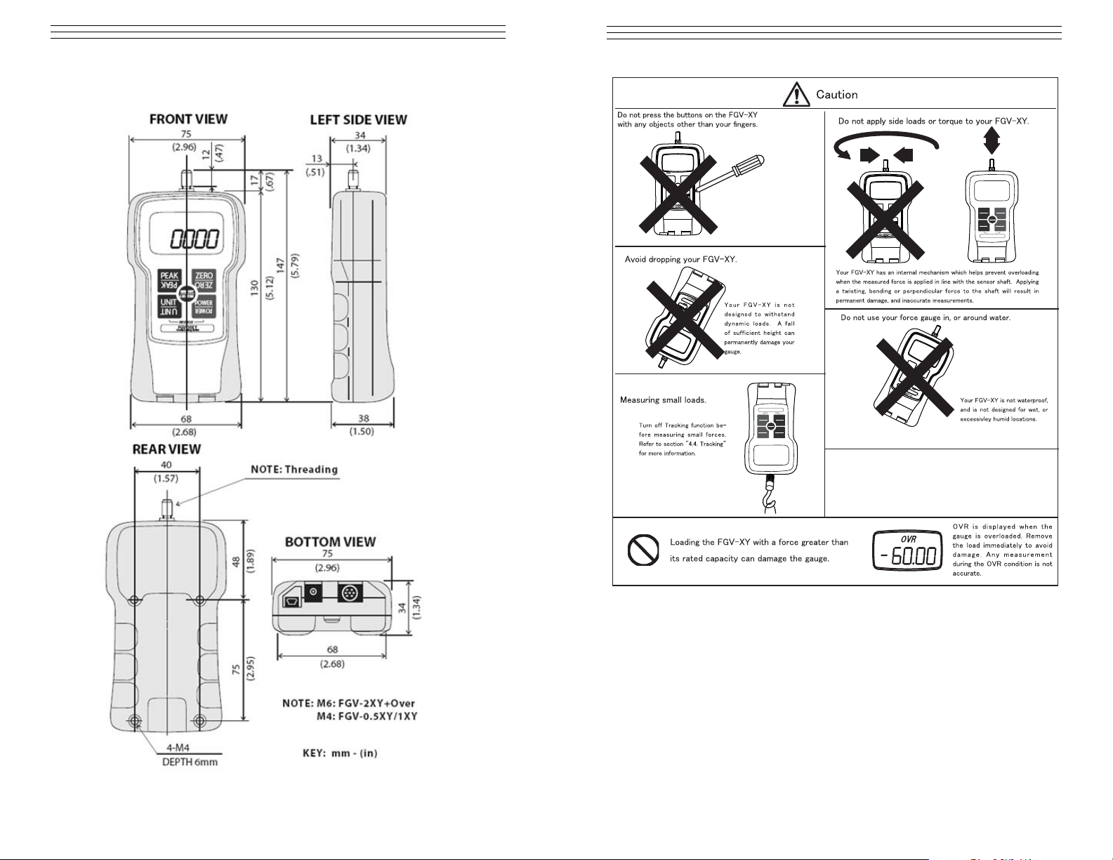
15.0 DIMENSIONAL DRAWINGS
Page 4
– 4 –
1.0 INTRODUCTION
The all new FGV-XY series force gauge delivers industry-leading value
with an extensive list of features including USB output, reversible display
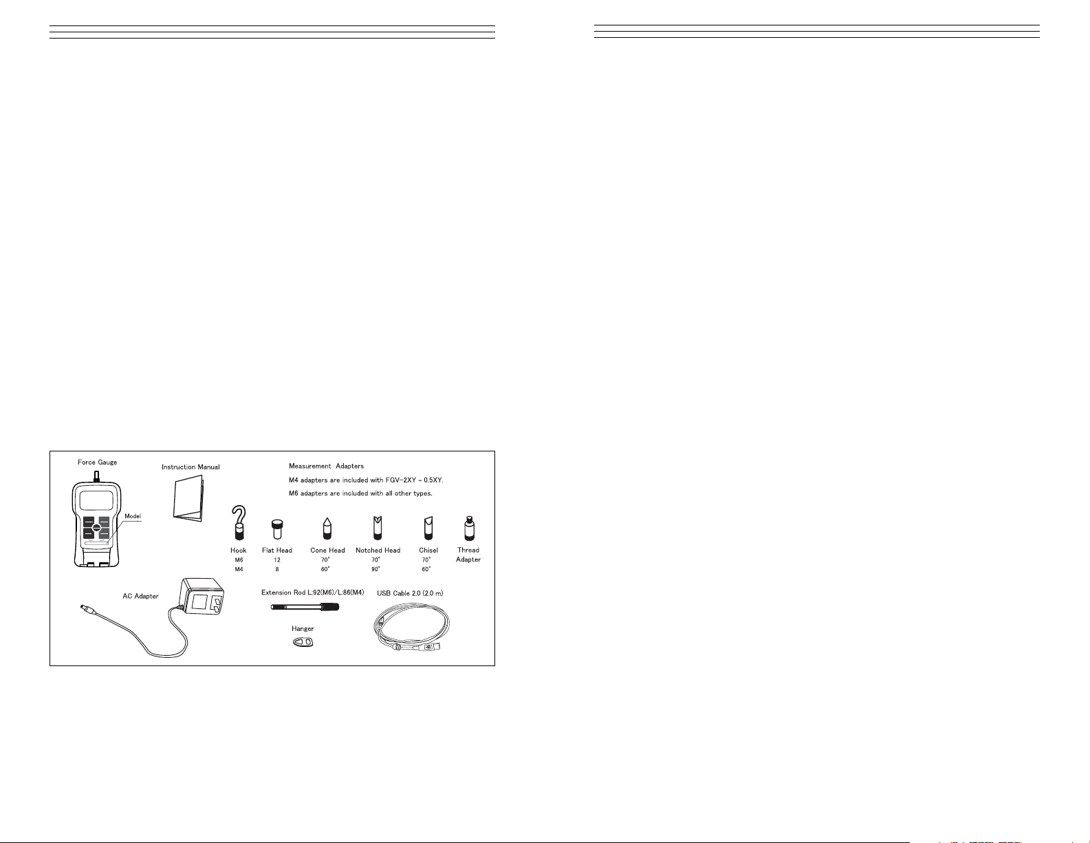
and a rugged metal housing. Each gauge is supplied as a complete kit with
several screw-on adapters providing a complete force testing instrument for
use in a wide variety of industries. All models include built-in memory for
1000 values, easily downloaded via the USB data output to a PC using the
software & cable supplied at no charge.
1.1 Standard Features
• Nickel-Hydrogen battery allows long periods of use.
• Data can be downloaded to PC via USB.
• 1000 points of data storage.
• Comparator feature for pass/fail testing.
• Broad range of capacities:
2.000N (200.0gf, 8 oz.) ~ 1000N (100.0gf, 200 lb).
• Reversible display with reversed keypad for upside down reading
• One touch operation to change the measurement unit N (kg (g), Lb (oz).
• Measures peak values for tension and compression.
• High speed measurement rate of 1000 times/second.
• Display update time as fast as 20 times/second.
1.2 Accessories Included
PEAK ZERO
MEM
UNIT
REVERSE
PEAK
PEAK
UNIT
UNIT
ZERO
ZERO
POWER
POWER
MEMORY
MEMORY
FGV-10XY
10.00lb/5.000kg/50.00N
– 33–
14.0 SPECIFICATIONS
Measuring Modes Realtime, Compression Peak, Tension Peak
Display Update Rate User Selectable: 1, 2, 3, 5, 10, 20 times per
second
Sampling Rate 1000 times per second (1000Hz/1KHz)
Accuracy ± 0.2% F.S.
Temperature Drift Gain : ± 0.01% LOAD / Zero : ±0.01% / R.C. /
Drift of zero point can be cancelled with tracking function.
Display Main display: 4-digits 12mm high,
Reversible Units display: 3-digits 7mm high
Overload 200% of Full Scale
On Model FGV-200XY: 150% F.S.
Tracking User Selectable (ON/OFF)
USB Output Allows communication between FGV-XY and Windows PC
Software with ToriemonUSB via USB cable(included).
RS-232C Output Allows communication between the FGV-XY and RS-232C
devices.
Analog Output ± 1V, Accuracy is ± 50mV through a 12 bit D/A.
ZERO affects this output, and is updated at
1000 times/second. Load is >10k Ohms
Overload/Comparator Open-collector output (Max DC30V/5mA). Output
Power Rechargeable Nickel hydride battery or AC adapter/charger.
Operating Time Approximately 8 hours after a full charge.
Charging Time: 16 Hours Max.
Auto Power Off Default is 10 minutes. Can be disabled.
Automatically disabled when connected to AC adapter.
Memory function Continuous memory: 1000 data points,
Single memory: 100 data points,
Standard memory: 50 data points Statistics functions (max,
minimum, peak, average, standard deviation)
Comparator function User Selectable: HI and LO
Temperature range –32 ~ 104° F (0 ~ 40° C)
Humidity range 35 ~ 85% RH
Dimensions 5.79" (L) x 2.95" (W) x 1.50 (H) (147 x 75 x 38mm)
Weight Approx. 15.87 oz. (450g)
On Model FGV-200XY: Approx.17.64 oz. (500g)
Software Free application software (USB version) available at
www.checkline.com/products/126333/fgv-xy_software_manual.zip
Page 5
– 5 –
2.0 OVERVIEW
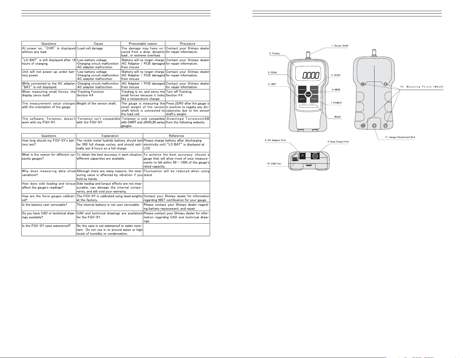
2.1 Main Unit
1. Sensor Shaft Apply your force in line with this threaded
shaft, using the included attachments,
2. Display LCD screen is the main information display
3. PEAK Press to change the measuring modes
4. UNIT Press to switch to available measurement units
5. ZERO Press in Standard mode to tare gauge. Pressing
in PEAK mode clears the current peak value
6. MEM Press in Standard mode to activate
measurement recording
7. POWER Press to turn the gauge on and off
8. AC Adapter Port Used for the provided AC Adapter
9. Data Output Port Used for data output option
10. USB Port Used to connect gauge to PC via USB
11. Hanger Attachment Secures the provided hanger attachment
Bolt
12. Threaded Holes Used to attach gauge to fixture or stand
REVERSE
PEAK
PEAK
UNIT
UNIT
ZERO
ZERO
POWER
POWER
MEMORY
MEMORY
FGV-10XY
10.00lb/5.000kg/50.00N
– 32 –
13.0 TROUBLESHOOTING / TECHNICAL QUESTIONS
Page 6
– 6 –
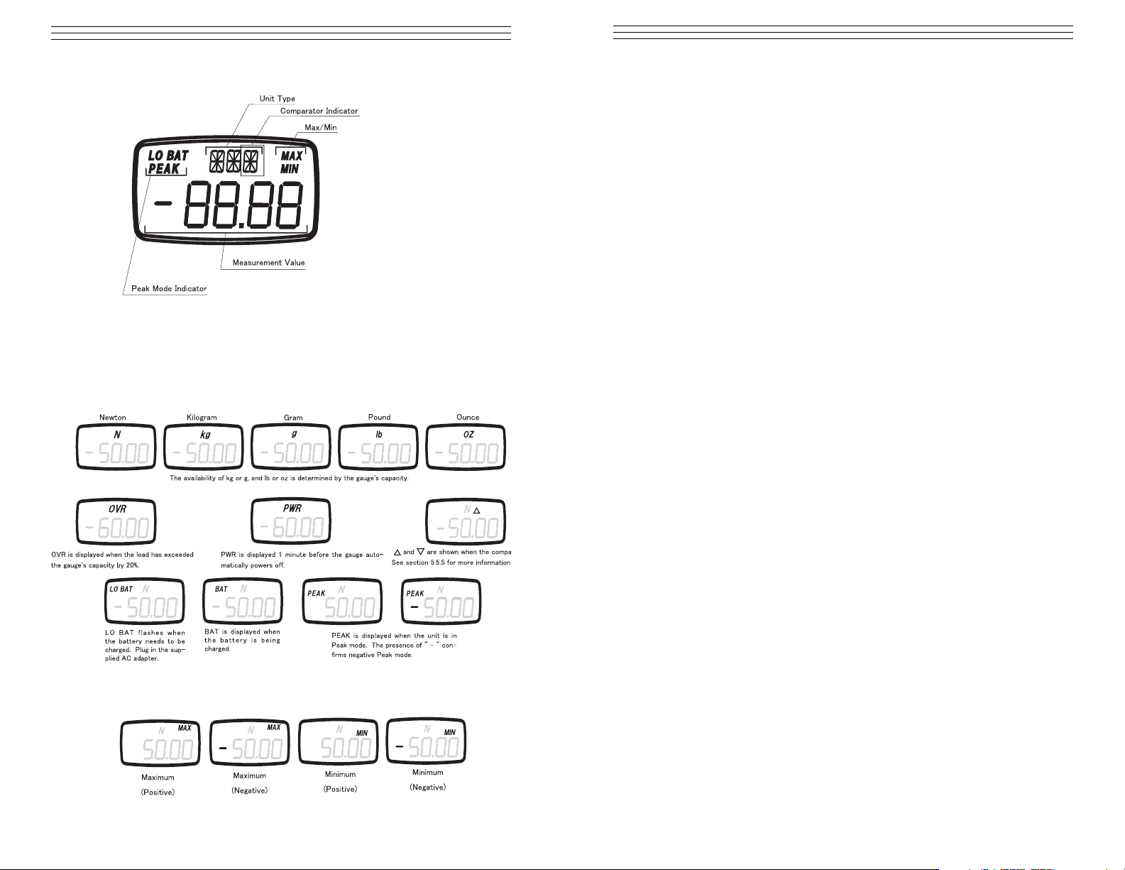
2.2 LCD Display
Note: The default setting for the four digit displays shows compression
loads as a positive force and tension loads as a negative force. to
reverse these settings, showing compression loads as negative and
tension loads as positive, see section 4.1 for setting f01.
2.3 Display Indicators
2.4 MAX/MIN display
– 31 –
Overload Output
When the overload condition is triggered, the corresponding overload output
turns on. this can be used to stop a motorized test stand, or an alarm to prevent damage from accidental overload.
When compression overload occurs photo-couple 1 (PC!) turns on, and
allows current to flow between pins 8 and 10.
When tension overload occurs photo-couple 2 (PC2) turns on and allows
current to flow between pins 9 and 10.
If no overload condition exists, PC1 and PC2 should be closed and will not
allow current flow.
Overload occurs at about 120% of the gauge’s rated capacity. this includes
any weight zeroed during any tare operation.
Comparator Output
When the LO limit is reached, photo-couple 1 (PC1) turns on and allows
current to flow between pins 8 and 10.
When the HI limit is reached, photo-couple 2 (PC2) turns on and allows
current to flow between pins 9 and 10.
Refer to section 7 regarding the activation and setting of Comparator
limits.
Page 7

– 7 –
3.0 SETUP
3.1 Battery Management
IMPORTANT: Use only the AC Adapter supplied with your FGV-XY. do
not use a third party adapter. Doing so could cause a fire or shock hazard.
1. To charge your FGV-XY, firmly
plug the AC Adapter into the
gauge’s power port and then plug
the Adapter into a wall outlet.
2. Charging begins automatically.
BAT appears on the display
during charging and disappears
when charging is complete.
NOTE: Charging time is up to 16 hours. Operating time on full charge is
approximately 8 hours. The FGV-XY is operable during charging
3. When battery power runs low, LO BAT appears on the display. If
the gauge is not plugged into an AC outlet, it will power off in
approximately one minute.
NOTE: Only charge the battery when LO BAT appears on the display.
Charging the unit before the battery is close to empty decreases battery life.
3.2 Using the Measurement Accessories
PEAKPEAK ZEROZERO
1.Select the measurement adapter for your application and lightly hand
tighten the accessory onto the sensor shaft.
Note: Overtightening an attachment with your hand or a tool can cause
permanent damage to the gauge. Do not use a tool to tighten Do not use a
broken, bent or damaged attachment.
– 30 –
12.5 Analog Output
±1 V analog output. The output voltage’s polarity corresponds to the
polarity shown on the display during standard measurement mode.
The analog output has a default update rate of 1000 time/second. The output
voltage is linearly scaled so that the current zero point of the gauge corresponds with 0V, and so that 1V corresponds with 100% of the gauge’s rated
capacity. this means that the tare function, or any change in the gauge’s zero
point, will change the maximum voltage shown before the gauge is overloaded.
12.6 Overload/Comparator Output
Page 8

– 8 –
3.3 Using The Hanger
The hanger allows your FGV-XY
to be hung from a fixture or winch.
It is shaped specifically to fit onto
gauge.
1. Remove the hanger bolt, place
the square end of the hanger in
the recessed area on the gauge
and tighten the hanger bolt
Be sure that your fixture, stand or
winch can support the gauge and
applied load.
3.4 Tracking Function
The FGV-XY uses a load cell and stain gauge as its force sensor. The sensor
is affected by environmental changes, such as temperature and humidity.
The Tracking Function , which is active by default, helps to negate the
effects of these changes.
NOTE: Tracking can cause errors when measuring very small forces. it is
recommended that tracking be turned off in these situations.
To turn Tracking off:
1. Make sure that the power is turned off.
2. Hold down the PEAK and UNIT keys.
3. With the PEAK and UNIT keys still
depressed, press POWER and hold
until “oFF” appears on the display.
To turn Tracking back on:
1. Repeat steps 1 –3 above.
2. Instead of “oFF”, “SEt” will appear
on the display. Tracking is now activated.
WARNING
– 29 –
12.3 RS-232C Communications Commands
Typical host to FGV-XY commands. “cr” means carriage return
12.4 Connection between FGV and Host
IMPORTANT: Without the connection between the Digital GND
and pin 5, RS-232C communications will not work.
Page 9

– 9 –
4.0 FUNCTION MODES
To access and modify the function modes, follow this procedure:
1. Make sure that the gauge is powered off
2. Press and hold the ZERO key.
3. While continuing to press and hold the ZERO key, Press and release the
POWER key.
4. Release ZERO after the display
shows “f01.”
5. Press UNIT to to change the setting
within the function selected.
OR
6. Press PEAK to save the current setting and move to the next Function Mode
IMPORTANT NOTE: To scroll through the Function Modes, press the PEAK
key repeatedly. The modes will appear in the order shown in the chart below.
OR
7. Press ZERO to save and exit the Function Modes.
Setting Unit Options Default
Measurement Polarity f01 -0.001 (minus), 0001 (plus) 0001
Display Update Time f02 1, 2, 3, 5, 10, 20, (times/second) 3
Auto Power Off f03 10 (10 minutes) oFF (always on) 10
RS232C Baud Rate f04 2400, 4800, 9600, 19200 bps 2400
Response Time f05 3, 20, 150 (msec) 3
Output Type f06 ovEr, Hi-Lo ovEr
4.1 Measurement Polarity (f01)
This function allows you to change whether compression is shown as a
positive or negative force. once the compression display has been changed,
the tension display will then read as the opposite of compression.
– 28 –
12.0 EXTERNAL DATA PORT
12.1 Pin Assignment
12.2 RS-232C Output
The RS-232C data connection allows control from external devices and data
transfers.
Interface
Baud rate* 2400, 4800, 9600, 19200 bps
Length of data bit 8 bit
Parity bit None
Length of stop bit 1 bit
Flow control None
*The baud rate is selectable through setting f04 (see section 4.4). The
default factory setting is 2400 bps. consult your equipment manual or
manufacturer for the correct baud rate. ASCII code, alpha numerics and carriage returns are used for RS-232C data transfer
6
2
1
3
7
4
5
8
10
9
Page 10

– 10 –
4.2 Display Update (f02)
This function allows you to change the rate at which the display is updated.
available times are 1, 2, 3, 5, 10 and 20 times a second.
Press UNIT to change the setting. Press PEAK to save and move to the
next Function Mode. Press ZERO to save and return to standard measuring
mode.
4.3 Auto Power Off (f03)
If the gauge is idle and there is no activity for 10 minutes, the unit automatically shuts off to conserve battery power. This option may be disabled,
and is automatically disabled when connected to the AC adapter.
Press UNIT to change the setting. Press PEAK to save and move to the
next Function Mode. Press ZERO to save and return to the standard measuring mode.
4.4 Baud Rate (f04)
This function allows you to change the RS-232C communications rate. The
available baud rates are 2400, 4800, 96000 and 19200.
Press UNIT to change the setting. Press PEAK to save and move to the
next Function Mode. Press ZERO to save and return to the standard
measuring mode.
– 27 –
11.0 USB COMMUNICATIONS
The USB port allows you to connect your FGV-XY to your PC via the supplied
USB cable. Our free software, TorriemonUSB, allows you to capture data directly
into Excel.* (*Excel is a registered trademark of Microsoft Corporation.)
TorriemonUSB is available for free download at
www.checkline.com/products/126333/fgv-xy_software_manual.zip.
11.1 Battery life and USB
Leaving the USB cable connected to the FGV-XY will drain the battery
power at a faster rate. Only connect the gauge when taking data, or use the
AC adapter for power when accessing data frequently
Page 11

– 11 –
4.5 Response Time (f05)
The gauges response time function smooths out the gauge’s sampling and
adjusts the sampling period accordingly. Response times are 3, 20 and 150
msec.
Press UNIT to change the setting. Press PEAK to save and move to the
next Function Mode. Press ZERO to save and finish.
4.6 External Output (f06)
This function allows the user to change between Overload and Comparator
type output. Press UNIT to change the setting.
Press UNIT to change the setting. Press PEAK to save and move to the
next Function Mode. Press ZERO to save and return to the standard
measuring mode.
– 26 –
10.0 CLEARING THE MEMORY
10.1 Clearing The Last Record
1. The last recorded memory block may be erased by pressing ZERO while
viewing the last data point.
2. If ZERO is pressed while viewing any other data point, the display will
show “Err” and will not delete anything.
10.2 Clearing All Memory
1. When viewing the last memory point, press and hold ZERO.
2. The display will show “nonE”.
3. All memory has been cleared and the gauge returns to
standard measuring mode
10.3 No Recorded Data
1. The display will show “nonE” is switching to memory mode when there
are no recorded memory points.
ZERO
ZERO
ZERO
ZERO
ZERO
ZERO
Page 12

– 12 –
5.0 REVERSING THE DISPLAY
If you have mounted your FGV-XY upside down, or are holding the gauge upside
down, the display may be reversed for readability
1. Turn POWER off.
2. Press and hold the UNIT key.
3. Press and release the POWER key while continuing to hold the UNIT key
until the display screen appears in reverse.
4. Release the UNIT key.
– 25 –
UNIT
UNIT
UNIT
UNIT
UNIT
UNIT
UNIT
UNIT
UNIT
UNIT
UNIT
UNIT
UNIT
UNIT
UNIT
UNIT
UNIT
UNIT
UNIT
UNIT
UNIT
Page 13

– 13 –
6.0 MEASURING MODES
6.1 Standard Measuring Mode
This mode shows the current force applied, tension/compression, on the
sensor shaft.
1. Press POWER to turn the FGV-XY on
2. Press ZERO to tare the gauge
3. If necessary, press and release PEAK until NO “PEAK” appears on the
display.
4. The measurement displayed is the average of the measured samples*
over the displays’s update time.
NOTE: The display update time is set to 3 times/second by default. This
can be increase up to 20 times sec (see section 4..2)
* This is dependent on the Response Time function (f05), see section 4.5.
6.2 Peak Measuring Mode
The PEAK mode displays the greatest force in both the positive and negative direction. Sampling time is 1ms.*
1. Press PEAK to change from Standard measuring mode to Peak mode.
Press PEAK again to enter positive or negative Peak mode
2. In the positive Peak mode, “PEAK” is displayed; while in the negative
Peak mode, PEAK and “—” are displayed.
* This is dependent on the Response Time function (f05), see section 4.5..
IMPORTANT!! While in either peak mode, ZERO will clear the current
peak mode, but will not tare the gauge
6.3 Change the Displays Units
1. To change the measurement unit, press UNIT. The units of measure
available with each gauge depends upon its capacity. See section 14.
– 24 –
9.3 Standard Memory Mode
Accessing Memory Data
1. Turn POWER off.
2. Press MEM and hold, then press and release POWER. Release MEM
when you see “STd” on the display. The unit will alternate between
showing the data block number and the recorded measurement value of
that block.
3. Press MEM to review the previous data block recorded.
4. Press UNIT to cycle through the available recorded statistics. In Standard
mode, the available statistics are as follows: positive maximum value,
negative maximum value, positive minimum value, negative minimum
value.
4. Press PEAK to output the recorded data via RS232C. See section 12.
NOTE: Pressing ZERO deletes the current data block, but only if you have
the last black selected.
MEM
MEM
MEM
MEMORY
MEMORY
MEMORY
MEMORY
MEMORY
MEMORY
Statistics Data
1. When in memory mode, UNIT will cycle through the available
statistics data.
2. Each press of UNIT will switch between the following items: positive
maximum value, negative maximum value, positive minimum value,
negative minimum value.
3. Press MEM to exit to the recorded measurement values.
4. Press the PEAK key to output the recorded memory via RS-232C.
(See section 12).
Page 14

– 14 –
6.4 Tare
NOTE: Press ZERO to reset the measured value. This will allow the gauge
to ignore any force currently applied to the sensor shaft. The ignored, or
tared, force is still counted with regards to the gauge’s overload condition.
Overload will occur when the force applied to the sensor shaft exceeds
the gauge’s rated capacity by 20%. Stop measuring and remove the load
immediately to avoid permanent damage to the gauge. Any measurements
taken in the overload range are not accurate.
1. Tare is automatically performed when the gauge is first powered on.
Statistics Data
1. When in memory mode, UNIT will cycle through the available
statistics data.
2. Each press of UNIT will switch between the following items: positive
maximum value, negative maximum value, positive minimum value,
negative minimum value, average value, standard deviation.
3. Press MEM to exit to the recorded measurement values.
4. Press PEAK key to output the recorded memory via RS-232C.
(See section 12).
NOTE: Pressing MEM exits statistics mode and returns to memory blocks.
– 23 –
MEM
MEM
MEM
MEM
MEM
MEMORY
MEMORY
MEM
MEM
MEMORY
MEMORY
MEM
MEM
MEMORY
MEMORY
UNIT
UNIT
UNIT
UNIT
UNIT
UNIT
UNIT
MEM
UNIT
UNIT
UNIT
UNIT
UNIT
UNIT
UNIT
UNIT
UNIT
UNIT
UNIT
UNIT
UNIT
UNIT
MEMORY
MEMORY
Page 15

– 15 –
7.0 COMPARATOR
The Comparator function allows you to create conditions for Go/No Go testing.
A high (HI) and low (LO) force limit may be set so that the FGV-XY’s display
will show when a measurement is not within the HI and LO settings. In addition,
the output port will respond relative to the display. See section 7.4 regarding the
comparator output.
NOTE: The FGV-XY must be in Comparator mode, and not Overload mode to
use the following settings. See section 4.5.6 regarding the output mode.
7.1 Memory Setting Mode
1. Turn POWER off, press PEAK and hold.
2. Press POWER and hold until “HI” appears on display, then release.
7.2 Setting the HI Limits
1. Press UNIT to select the HI Setting. The digits will
start flashing
2. Press UNIT again to change the polarity.
3. Choose the digit to change by pressing ZERO.
4. Press UNIT to increase the selected digit to the desired
value.
5. Repeat steps 3 and 4 until the desired value and polarity
are correct.
6. Press PEAK. This saves the HI limit and displays
the LO limit.
7. Press MEM if you are finished.
Setting Display Content Default Factory Setting
Comparator HI limit HI Value for HI limit* 0
Comparator LO limit LO Value for LO limit* 0
Memory Mode MEM Memory Mode Std
(Standard, Single, Continuous)
* When HI and LO are set to 00.00 the Comparator function is disabled.
– 22 –
9.2 Single Memory Mode
Accessing Memory Data
1. Turn POWER off.
2. Press MEM and hold, then press and release POWER.
3. Release MEM when you see “Slg” on the display. The unit will alternate
between showing the data block number and the recorded measurement
value of that block.
4. Press MEM to review the previous data block recorded.
5. Press UNIT to cycle through the available recorded statistics. In Single
mode, the available statistics are as follows: positive maximum value,
negative maximum value, positive minimum value, negative minimum
value, average value, standard deviation.
6. Press PEAK to output the recorded data via RS232C. See section 12.
NOTE: Pressing ZERO deletes the current data block, but only if you have
the last black selected.
UNIT
UNIT
UNIT
UNIT
UNIT
UNIT
UNIT
UNIT
UNIT
MEM
UNIT
UNIT
UNIT
UNIT
UNIT
UNIT
UNIT
UNIT
UNIT
UNIT
UNIT
UNIT
UNIT
UNIT
UNIT
UNIT
UNIT
UNIT
MEM
MEM
MEMORY
MEMORY
PEAK
PEAK
PEAK
PEAK
PEAK
PEAK
Page 16

NOTE: The values entered for the HI and LO settings are displayed in the
measurement units last used in Standard Mode.
NOTE: The absolute value of the HI limit can never be lower than the
absolute value of the LO limit.
7.3 Setting the LO Limit
1. Press UNIT to select the HI Setting. The digits will
start flashing.
2. Press PEAK. This saves the HI limit and displays
the LO limit.
3. Press UNIT again to change the polarity.
4. Choose the digit to change by pressing ZERO.
5. Press UNIT to increase the selected digit to the desired value.
6. Repeat steps 3 and 4 until the desired value and polarity are correct
7. Press MEM if you are finished with the Comparator and Memory
settings.
NOTE: The absolute value of the LO limit can never be higher than the
absolute value of the HI limit.
7.4 Comparator Display
The following symbols are shown when the Comparator function is active:
NOTE: In order for the Comparator function to display, the Comparator
output option must be set in function f06. See section 4,.6 regarding this
setting.
7.5 Comparator Output
The Comparator function also allows control of an alarm or automated
process through its data output port. When the measured value is greater
than the HI limit, the corresponding photo-couple is triggered. When the
measured value is lower than the LO limit, the corresponding photo-couple
is triggered.
NOTE: In order for the Comparator function to display, the Comparator
output option must be set in function f06. See section 4.6 regarding this
setting.
NOTE: For connection and circuit information pertaining to the
Comparator output see section 12.6.
– 16 –
WARNING
The Comparator function’s limits can be set outside of the FGV-XY’s working
range. This may cause unpredictable results, and is not recommended
– 21 –
9.0 REVIEWING MEMORY DATA
9.1 Continuous Mode Memory
Accessing Memory Data
1. Turn the POWER off.
2. Press MEM and hold, then press and release POWER. Release MEM
when you see “CNT” on the display. The unit will alternate between
showing the data block number and the recorded measurement value of
that block.
3. Press MEM to review the previous data block recorded.
4. Press UNIT to cycle through the available recorded statistics. In
Continuous mode the available statistics are as follows: positive
maximum value, negative maximum value, positive minimum value,
negative minimum value, positive peak value, negative peak value,
average value, standard deviation
5. Press PEAK to output the recorded data via RS232C. See section 12.
NOTE: Pressing ZERO deletes the current data block, but only if you have
the last black selected
Statistics Data
1. When in memory mode, UNIT will cycle through the available
statistics data.
2. Each press of UNIT will switch between the following items: positive
maximum value, negative maximum value, positive minimum value,
negative minimum value, positive peak value, negative peak value,
average value, standard deviation.
3. Press MEM to exit to the recorded measurement values.
4. Press PEAK key to output the recorded memory via RS-232C.
(See section 12).
NOTE: Pressing MEM exits statistics mode and returns to memory blocks.
MEM
MEM
MEM
MEM
MEM
MEM
MEMORY
MEMORY
MEMORY
MEMORY
MEMORY
MEMORY
Page 17

– 17 –
8.0 SETTING MEMORY MODE / RECORDING DATA
The FGV-XY has three memory modes:
Continuous Memory: Allows the recording of up to 1000 data points. the
recording starts when you push MEM, and stops when you push MEM. In
addition, the following statistics, gathered between that start and stop, are
recorded; positive maximum value, negative maximum value, positive minimum
value, negative minimum value, positive peak value, negative peak value, average
value, standard deviation.
Single Memory: Allows the recording of up to 100 data points. every time MEM
is pressed, the value shown on the display is memorized. if the unit is in Standard
mode then the current measured value is recorded. In Peak mode, the unit records
the displayed peak value, in addition, the following statistics are recorded;
positive maximum value, negative maximum value, positive minimum value,
negative minimum value.
Standard Memory: Allows the recording of up to 50 data points. The recording
process is similar to Continuous mode. MEM starts the recording and stops the
recording. The measured value when MEM is pushed the second time, is recorded
as a point. the following statistics, gathered between the start and stop, are
recorded: positive maximum value, negative maximum value, positive minimum
value, negative minimum value.
Memory Terms Defined
Measurement Value: The current displayed value in Standard Mode.
Positive Maximum Value (+Max): Maximum value in the positive direction.
Negative Maximum Value (–Max): Maximum value in the negative direction.
Positive Minimum Value (+Min): Minimum value in the positive direction.
Negative Minimum Value (–Min) Minimum value in the negative direction.
Average Value (AVE): Average of the recorded measurement values
Standard Deviation (DEV): Standard deviation of the recorded measurement
values
Positive Peak Value: Largest value in the positive direction.
(This value is sampled at 1000 times per second.)
Negative Peak Value: Largest value in the negative direction.
(This value is sampled at 1000 times per second.)
Last Measurement Value (LST): The last measurement value displayed at the
corresponding time.
– 20 –
Single Mode:
1. In the Single Measurement Mode, Press MEM to start the recording.
The letter M will appear and start blinking. Press M to stop recording.
2. If 1000 points of data are recorded, the display will show FULL and
return to standard measurement mode.
Standard Mode:
1. In the Standard Measurement Mode, Press MEM to start the recording.
The letter M will appear and start blinking. Press M to stop recording.
2. If 1000 points of data are recorded, the display will show FULL and
return to standard measurement mode.
Page 18

– 18 –
8.1 Setting the Memory Mode
1. Turn the POWER off.
2. Press PEAK and hold, then press and release POWER.
The display will show the HI Comparator limit
3. Press PEAK twice to display the current memory mode.
4. Press UNIT to cycle the Memory mode
5. Press MEM to save and exit.
The following items are found in the Comparator/Memory mode settings.
Setting Display Content Default Factory Setting
Comparator HI limit HI Current HI limit 0
Comparator LO limit LO Current LO limit 0
Memory Mode MEM Current Memory Mode Std
– 19 –
MEMORY
MEMORY
Setting the Memory Mode
8.2 Recording Memory Data
The following procedures explain how to activate memory recording for
each memory mode
Continuous Mode:
1. In the Continuous Measurement Mode, Press MEM to start recording.
The letter M will appear and start blinking. Press M to stop recording.
2. If 1000 points of data are recorded, the display will show FULL and
return to standard measurement mode.
PEAK
PEAK
PEAK
PEAK
PEAK
PEAK
UNIT
UNIT
UNIT
PEAK
PEAK
PEAK
UNIT
UNIT
UNIT
UNITUNIT
UNIT
MEM
Page 19

Model FGV-XY
DIGITAL FORCE GAUGE
Operating Instructions
CHECK•LINE
®
BY ELECTROMATIC
ELECTROMATIC
E Q U I P M E N T C O., I N C.
600 Oakland Ave., Cedarhurst, NY 11516–U.S.A.
TEL: 516-295-4300
• FAX: 516-295-4399
CHECK•LINE
®
INSTRUMENTS
 Loading...