


10.00 WARRANTY
ELECTROMATIC Equipment Co., Inc. (ELECTROMATIC) warrants to the original purchaser that this product is of merchantable quality and confirms in kind and quality with the descriptions and specifications thereof. Product failure or malfunction arising out of any defect in workmanship or material in the product existing at the time of delivery thereof which manifests itself within one year from the sale of such product, shall be remedied by repair or replacement of such product, at ELECTROMATICÕs option, except where unauthorized repair, disassembly, tampering, abuse or misapplications has taken place, as determined by ELECTROMATIC. All returns for warranty or non-warranty repairs and/or replacement must be authorized by ELECTROMATIC, in advance, with all repacking and shipping expenses to the address below to be borne by the purchaser.
THE FOREGOING WARRANTY IS IN LIEU OF ALL OTHER WARRANTIES, EXPRESSED OR IMPLIED, INCLUDING BUT NOT LIMITED TO, THE WARRANTY OF MERCHANTABILITY AND FITNESS FOR ANY PARTICULAR PURPOSE OR APPLICATION. ELECTROMATIC SHALL NOT BE RESPONSIBLE NOR LIABLE FOR ANY CONSEQUENTIAL DAMAGE, OF ANY KIND OR NATURE, RESULTING FROM THE USE OF SUPPLIED EQUIPMENT, WHETHER SUCH DAMAGE OCCURS OR IS DISCOVERED BEFORE, UPON OR AFTER REPLACEMENT OR REPAIR, AND WHETHER OR NOT SUCH DAMAGE IS CAUSED BY MANUFACTURERÕS OR SUPPLIERÕS NEGLIGENCE WITHIN ONE YEAR FROM INVOICE DATE.
Some State jurisdictions or States do not allow the exclusion or limitation of incidental or consequential damages, so the above limitation may not apply to you. The duration of any implied warranty, including, without limitation, fitness for any particular purpose and merchantability with respect to this product, is limited to the duration of the foregoing warranty. Some states do not allow limitations on how long an implied warranty lasts but, not withstanding, this warranty, in the absence of such limitations, shall extend for one year from the date of invoice.
ELECTROMACTIC Equipment Co., Inc.
600 Oakland Ave. Cedarhurst, NY 11516ÑUSA
Tel: 1-800-645-4330/ Tel: 516-295-4300/ Fax: 516-295-4399
OI810B
INDEX
1.00 |
INTRODUCTION . . . . . . . . . . . . . |
. . 2 |
7.00 |
CALIBRATION . . . . . . . . . . . . . . . . |
16 |
|||
2.00 |
DTMB OVERVIEW |
3 |
|
7.10 |
Checking Calibration |
|
||
|
7.20 |
Field Calibration Adjustment |
|
|||||
|
|
|
|
|
|
|||
3.00 |
DESCRIPTION OF KEYS . . . . . . . |
. . 4 |
|
7.30 |
Special Calibraton |
|
||
4.00 |
QUICK START INSTRUCTIONS |
. . 5 |
8.00 |
GENERAL NOTES . . . . . . . . . . . . . |
19 |
|||
|
4.10 |
Setup |
|
|
8.10 |
Turning Power On/OFF |
|
|
|
4.20 |
Operation |
|
|
8.20 |
Display Indicators & Codes |
|
|
5.00 |
SETUP |
8 |
|
|
8.21 |
Over Range |
|
|
|
|
8.22 |
EPROM Error |
|
||||
|
5.10 |
Installing Batteries |
|
|
|
|
||
|
|
|
|
8.23 |
Low Battery |
|
||
|
5.20 |
AC Adapter |
|
|
|
|
||
|
|
|
8.30 |
Options |
|
|||
|
5.30 |
Configuring Dip Switches |
|
|
|
|||
|
|
|
|
8.31 |
Ultra-High Speed Rollers |
|
||
|
5.31 |
Access the DIP Switch Block |
|
|
|
|||
|
|
|
8.32 |
Lever |
|
|||
|
5.32 |
Setting the DIP Switches |
|
|
|
|
||
|
. |
|
|
8.33 |
AC Adapter |
|
||
|
5.40 |
Thickness Compensator |
|
|
|
|
||
|
|
|
|
8.34 |
Special Calibration |
|
||
|
5.41 |
Preparing Sample |
. |
|
|
|
||
|
|
8.40 |
On-Line Mounting Holes |
|
||||
|
5.42 |
Inserting Sample |
. |
|
|
|||
|
9.00 |
SPECIFICATIONS |
22 |
|||||
|
5.50 |
Gravity Correction (Zero) |
|
|||||
6.00 |
BUILT-IN MEMORY SYSTEM . . . . 14 |
10.00 |
WARRANTY . . . . . . . . . . . . . . . . . . |
24 |
||||
6.10Standard Memory
6.11Viewing Data
6.12Clearing Data
6.20 Standard NAPO Memory
24 |
1 |

1.00INTRODUCTION
The CHECK¥LINE¨ DTMB Digital Tension Meter is a hand-held device which accurately measures the running as well as static tensions of a wide variety of process materials including yarns, fibers, wires, optical fibers, etc. It employs the "three-roller principle" of tension measurement where the outer two reference rollers are fixed to create a known angle of wrap over the middle sensing roller. The middle roller is part of a precision strain gauge sensing system which accurately measures the resulting force on the roller. This value is converted into a highly accurate and repeatable tension value using proprietary computer calibration formulas which correct for different material diameters, gravity and other critical parameters. The DTMB is powered by four AA batteries and is supplied in a rugged, die-cast aluminum housing.
The DTMB takes 62 tension measurements per second and displays the average of these measurements over a user-selected interval of 0.5, 1, 2 or 4 seconds, the Display Update Rate. This permits the user to determine the extent of averaging (or damping) required to "stabilize" the tension readings, making them much easier to read and eliminating the undesirable "bouncing needle" condition found on most mechanical tension meters. To set or change the Display Update Rate, refer to Configuring Dip Switch Settings, Section 5.30.
A built-in memory system is provided which permits storage of the maximum, minimum and peak values occurring during a measuring interval. These values can be recalled to the display for viewing.
Specifications
Measuring Principle |
Strain gauge |
|
|
Measuring Frequency |
16 msec (62.5 samples/sec) |
|
|
Deflection of Sensing Roller (max.) |
0.2 mm |
|
|
Overload Capacity |
200% of Full Scale |
|
|
Temperature Coefficient |
Zero: less than + 0.3% FS/ ¡C |
Span: less than + 0.01% FS / ¡C |
|
Display |
|
4-Digit LCD, 12 mm high |
|
Display Update Rate |
0.5, 1.0, 2.0 or 4.0 seconds, dip-switch selectable |
||
Memory System |
Last, maximum, minimum and peak values |
||
Overrange Indicator |
Value will blink on/off, then ÒFFFFÓ |
||
Field Calibration Adjustment |
+ 7 steps, 1.5% per step |
|
|
Battery Type |
|
Four (4) 1.5 V AA (included) |
|
Battery Life |
|
20 hours, continuous use |
|
Auto Power Off |
|
After 2 minutes of non-use |
|
Roller Material (standard) |
Hard-coated Aluminum |
.. |
|
. |
(optional) |
Hardened Steel (ST), Ceramic (CE), Plastic (PL) |
|
Maximum Speed (standard) |
2000 m / min |
... |
|
. |
(optional) |
5000 m / min |
|
Housing |
|
Die-cast Aluminum |
|
Dimensions |
|
2.95" W x 10.83" H x 1.77" D (75 x 275 x 45 mm) |
|
Weight (approximate) |
1.43 lbs. (650 g) |
|
|
Operating Temperature |
32 to 132 ¡F (0 to 45 ¡C) |
|
|
Accessories Included |
4 AA batteries and operating instruction guide, all in a fitted, |
||
|
|
hard-plastic carrying case |
|
Warranty |
|
One year |
|
2 |
23 |

10.00 SPECIFICATIONS |
|
|
2.00 DTMB OVERVIEW |
|
|
|
Outer Roller Bracket |
|
|
Outer roller spacing c:c |
|
153 |
60 |
2.5KB–10 KB |
100 mm |
20KB– 50 KB |
200 mm |
||
|
|
|
Filament |
37 |
|
38 65 76 |
|
Display Symbols
• MAX
• PEAK
• BATT
• MIN
15 |
|
12 |
Sample Holding |
|
|
|
Clips |
40 |
45 |
48 |
|
||
|
|
Thumbpiece
192
All dimensions in mm
Model Data
|
|
|
|
|
|
|
|
|
|
Model |
DTMB-200 |
DTMB-500 |
DTMB-1K |
DTMB-2K |
DTMB- 2.5KB |
DTMB-5KB |
DTMB-10KB |
DTMB-20KB |
DTMB-20KB |
|
|
|
|
|
|
|
|
|
|
Tension Range (grams) |
0.1Ð200.0 |
0 .1Ð 500.0 |
50 Ð1000 |
200 Ð2000 |
250 Ð 2500 |
500 Ð 5000 |
1.00 Ð 10.00 Kg |
2.00 Ð20.00 Kg |
50 KB |
|
|
|
|
|
|
|
|
|
|
Accuracy |
+ 1.0% or better |
|
|
+ 1.5% or better |
|
|
|
||
|
|
|
|
|
|
|
|
|
|
Outer Roller Dist. (c:c) |
38 mm |
38 mm |
38 mm |
38 mm |
100 mm |
100 mm |
100 mm |
200 mm |
200 mm |
|
|
|
|
|
|
|
|
|
|
Filament Guide
Rollers
Middle Sensing
Roller
LCD Display
Slide Guide Plate
Thickness Compensator
(on back of unit)
STORE Key
Field Calibration
Adjustment
Recall Key
Power/Exit Key
22 |
3 |
3.00 DESCRIPTION OF MEMBRANE KEY FUNCTIONS
Key |
Description of Functions |
|
||
|
|
|
|
|
STORE |
¥ |
Starts/Stops scanning for Max/Min/Peak values. (Standard Memory) |
|
|
|
¥ |
Starts/Stops automatic recording of values into memory (Continuous Data Logging Model). |
|
|
|
|
¥ |
Loads displayed value into memory (On-Demand Data Logging Model). |
|
|
|
|
|
|
|
|
¥ |
Enters Recall Mode to review statistics and recorded Data. |
|
RECALL |
|
¥ |
In recall mode, changes display from LAST MAX MIN PEAK LAST MAX etc. |
|
|
¥ |
When in Data Logging Mode: changes display from LAST MAX MIN PEAK. |
|
|
|
|
|
||
|
|
|
AVERAGE STANDARD DEVIATION DATA #1 DATA #2 DATA #3 etc. |
|
|
|
|
|
|
|
|
¥ |
Turns power on. |
|
POWER |
|
¥ |
Turns power off if pressed and held for 5 or more seconds. |
|
EXIT |
|
¥ |
Exits from Recall Mode when reviewing data. |
|
|
|
|
|
|
|
|
¥ |
Clears all data in Basic Memory (ÒCCCCÓ momentarily shown on display). |
|
STORE + RECALL |
|
|
|
|
|
|
|
|
|
|
|
¥ |
Zeros gauge (ÒTareÓ) for use in any orientation (ÒGravity CorrectionÓ). |
|
RECALL + POWEREXIT |
|
|
|
|
*¥ Changes units of measure from grams (or Kg) to pounds (or ounces) and back again
POWER |
+ STORE |
each time this key combination is pressed. |
EXIT |
|
|
* When the units of measure are changed to grams, the ÒgfÓ indicator will momentarily flash on and then turn off. Otherwise the Òlb.Ó or ÒozÓ indicators will be shown.
8.34 Special Calibration
If the standard Factory Calibration and the Field Calibration Adjustment does not provide the desired accuracy, a Special Calibration can be ordered. A l0' sample of the process material must be provided for calibration purposes.
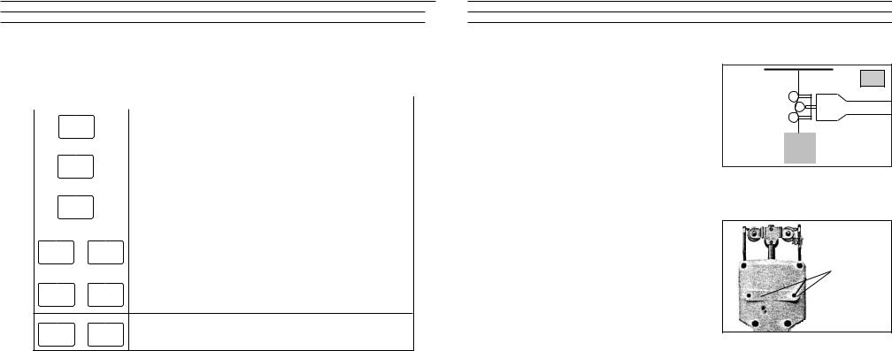
8.40 On-Line Mounting Holes
The DTMB is supplied with two threaded holes for on-line mounting in a fixed position when performing measurements over an extended period.
Thread Size |
M5 (metric) |
Thread Depth |
7.5 mm (max.) |
SP
W
Mounting holes
4 |
21 |
 Loading...