

Page 1
Model FGS-100PXH / FGS-100PXL
Programmable Motorized Test Stands
Congratulations on your purchase of the FGS-100PX series Shimpo test stand(s). This manual explains
how to operate your equipment safely and correctly.
Read the entire instruction manual before initial set-up and operation; the information
contained herein will help you in operating your Shimpo Programmable Motorized
Test Stand.
Page 2

For questions and inquiries regarding our product(s), call your local Shimpo representative or contact
Shimpo Instruments directly for assistance.
Nidec-Shimpo America Corporation
1701 Glenlake Avenue
Itasca, Illinois 60143
1-800-237-7079
Caution warning holds important safety information.
Reminder: holds important keep information for the product.
Manual Index
Inspection/Standard Accessories
1.0 Features and Benefi ts .............................................................................................. 3
2.0 Important Safety Instructions
Set up Procedures .......................................................................................................... 4
4. Units of Measure: English or Metric .........................................................................5
4.1 Display Panel .........................................................................................................6-7
5.0 Operation Modes
5.1 MANU (Manual Mode) ...............................................................................................8
5.2 JOG (Jog Mode) ........................................................................................................ 9
5.3 SING (Single Mode) ................................................................................................10
5.4 CONT (Continuous Mode) ......................................................................................11
5.5 PROG (PROGRAM Mode)..................................................................................12-15
6.0 RS232C Output Format (using FGV-X Force Gauges) ...................................15-16
7.0 Troubleshooting
8.0 Test Stand Specifi cations .................................................................................16-18
9.0 Dimensions and Drawings .....................................................................................19
Warranty ........................................................................................................................20
2
Page 3
Inspection/Standard Accessories
If any shipping damage is detected upon receiving the test stand, please do not unpack the unit.
Notify your shipping carrier immediately for damage claim instructions.
Refer to the nameplate located on the back of the test stand to confi rm model number ordered,
record serial number for future reference.
MODEL SPEED
FGS-100PXL 0.19 - 4.72 inch/min (5.00 - 120 mm/min)
FGS-100PXH
(3) M5 x 6 screws
(1) 5mm Allen wrench
(4) M4 x 8 screws
(1) Force gauge to Test Stand Interface cable (FGV-FGS250P)
(1) Analog output cable (FGS-ANALOG)
Manual
Warranty Card
0.79 – 19.69 inch/min (20-500 mm/min)
1.0 Features and Benefi ts
Shimpo’s FGS-100PXH (standard speed) and FGS-100PXL (low speed) Programmable Motorized
Test Stand offers:
All steel construction which guarantees durability and stability for production, laboratory
and quality control applications
Programmable FORCE and Distance(length)limits
Dual speed controls are optimally positioned to adjust test and return travel rates of the
drive assembly.
Drive assembly accepts a universal mounting plate, enabling the interfacing of a large
selection of force gauge models (contact Shimpo for specifi c models)
4½ digital LED display indicates displacement rate and distance of the drive assembly.
Analog output (10mV/mm) is convenient for data acquisition requirements.(used with
FGS-ANALOG cable)
3
Page 4
2.0 Important Safety Instructions
Read this section carefully before initial set up.
Position test stand on a level, heavy-duty table.
Confi rm that the test stand case is properly grounded to the AC line.
Keep hands, hair and jewelry away from stand when drive assembly is in motion.
Operate the membrane keypad with care. Do not use sharp objects that may puncture
the overlay.
Always wear eye protection when testing materials.
Do not store or use in oily, dusty, humid or wet areas
Ensure that AC power is removed (off) from test stand before making any adjustments.
If ALARM LED indicates drive assembly has been overloaded, immediately switch the
power switch to the off position and correct the overload condition. Wait at least two minutes
before restarting the test stand.
3.0 Set up Procedures
1. Connect all the necessary cables and AC cord before applying power to the test stand.
IF communication between the force gauge and test stand is desired, using an FGV-X or
FGV-XY force gauge, use cable part number FGV-FGS250PV to connect the force gauge
to the test stand.
IF communication between the force gauge and test stand is desired, using a DFS force
gauge, use cable part number FGS-50PCABLE to connect the force gauge to the test
stand.
2. If communication between the force gauge and test stand is desired, turn on the force gauge
before turning on the test stand; this is necessary for the test stand to recognize the connected
Shimpo force gauge.
3. T 3. The power switch for the test stand is located on the rear of the unit. After power is applied,
all the segments and LED’s will execute a power up and self test. After the self test, the test stand
will display 0.00 (inches - English) or 0.0 (mm – metric).
NOTE: I NOTE: If after power up, the test stand takes longer to initialize and a “no_F” display is observed
from the display, check the (force gauge to test stand) cable, FGV-FGS250PV, and the baud rate setting for
the FGV-X or FGV-XY force gauge (19200 baud). (See your force gauge manual for baud rate communication
and set-up) The FGS-100PXH/100PXL test stands communicate at 19200 baud with the Shimpo FGV-X and
FGV-XY force gauges. As noted above, if using a Shimpo DFS force gauge, (9600 baud max) use cable part
number FGS-50PCABLE, which provides DFS to test stand and PC communication capability.
NOTE: The FGS-50PCABLE cable incorporates a segment of cable that attaches to the test stand and
another that attaches to a PC.
4
Page 5
4. Units of Measure: English or Metric
To switch from English to metric units, push the “Speed” and “RST” buttons while turning the power on.
To return to English units turn the stand off and push the “SPEED” and “Time/>” buttons while turning the
power back on.
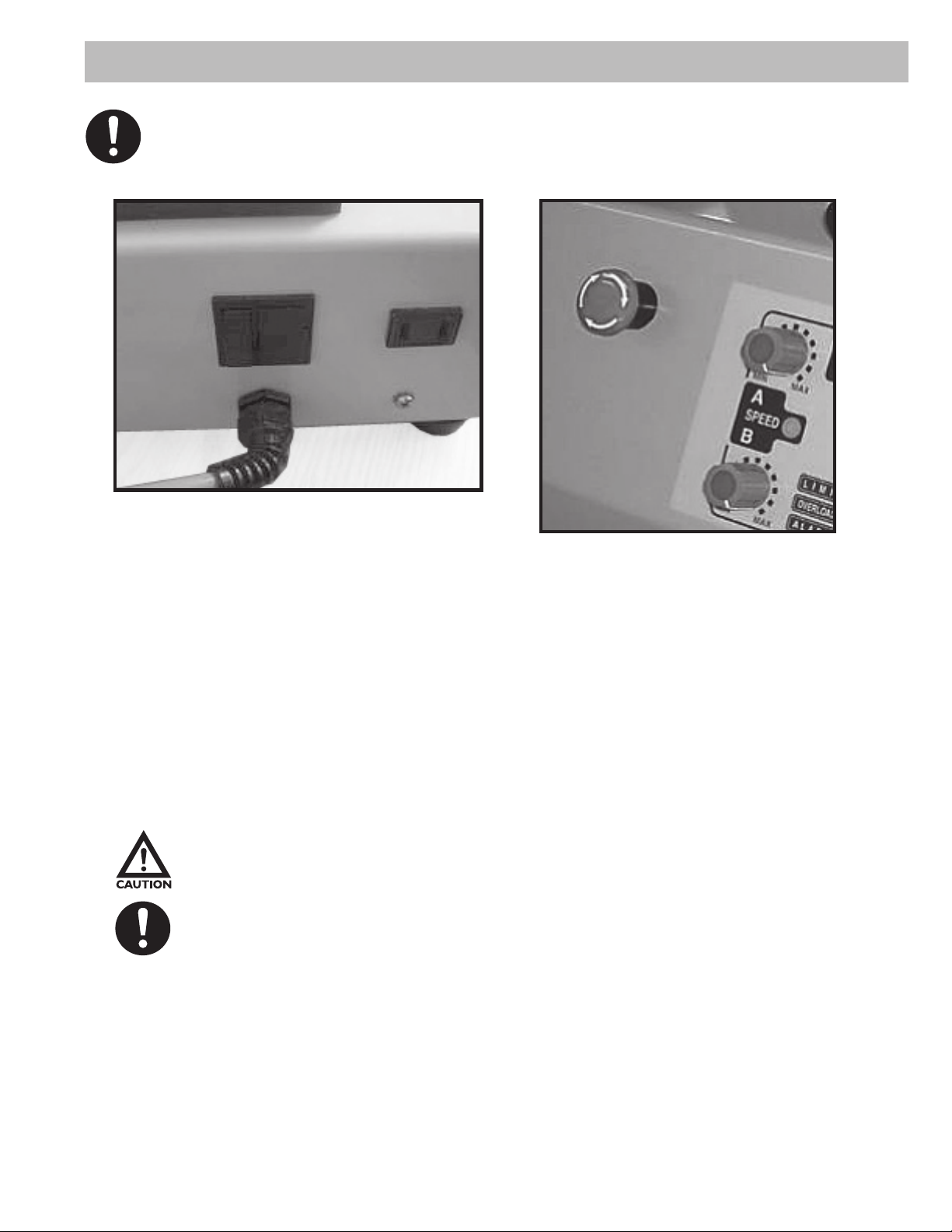
AC Power cord and AC plug for the Force
gauge, located on the back of the rear of
the test stand.
Emergency Stop button located on
the side of the front plate. Turn the
button Clockwise to release.
To identify whether the stand is in metric or English units, turn the power on. (power switch is
located in the back of the unit), Metric units will show one decimal place (0.0), while English
units show two decimal places (0.00) To change to metric units, push “A/SPEED/B” and “RST/^”
switches while turning the power on. To change to English units, push “A/SPEED/B” and “TIME/<”
switches while turning the power on.
Caution warning holds important safety information.
REMINDER: holds important keep information for the product.
5
Page 6
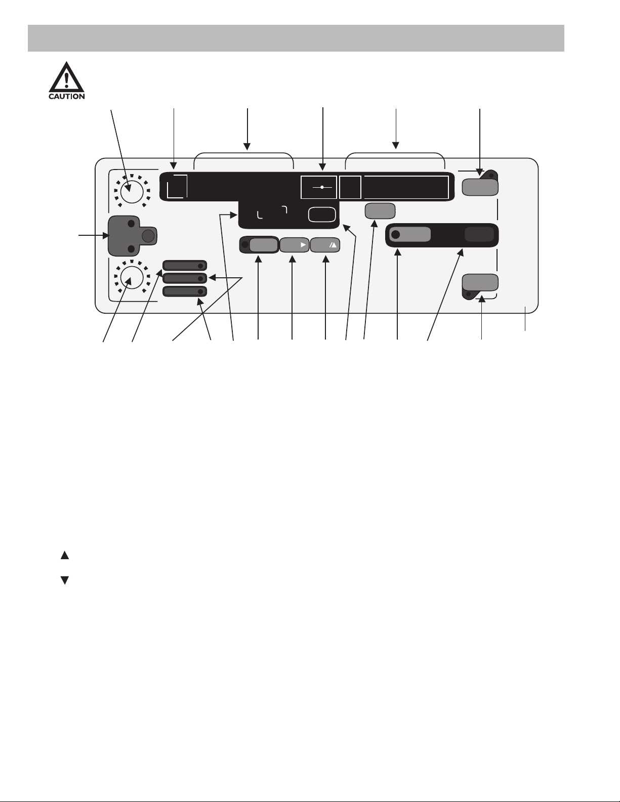
4.1 Display Panel
4.1 Display Panel
Figure 1
15
No
MIN MAX
A
3
SPEED
B
LIMIT
OVERLOAD
ALARM
14 15 8 18 17 16 12 19 24 22 23
2
MIN MAX
13
4, 6, 7 9, 10, 11 20 21
TIME
SEC
TIMESET
LENGHT
SPEED
ZERO
RST
PROG
CONT
MODE
SNG
JOG
PROG
START
MANU
PULL
STOP
PUSH
25
1. A Speed: Changes the left movement or upward speed (Continuous and Program Mode).
2. B Speed: Changes the right movement or downward speed. (Continuous and Program
Mode).
3. Speed: Selects speed control knob A or B.
4. Length, Speed or Cycle Display: Displays length, speed or cycle of a program when power
is on. Note: Cycle Display can only be selected in mode SING, CONT or PROG.
5. No: Displays program cycle (0-9).
6. : Indicates high limit value in all modes.
7. : Indicates low limit value in all modes.
8. TIME: Displays programmed delay time between program cycles.
9. LENGTH, SPEED, or Cycle: Selects display of length, speed or cycle of a program.
10. LED LENGTH Indicator: Indicates that length is being displayed.
11. LED SPEED Indicator: Indicates that speed is being displayed. Cycle display is indicated
when both Length and Speed LED’s are off.
12. ZERO: Resets length measurement to zero.
6
Page 7

13. LIMIT LED: Indicates one of the manual limit switches has been tripped.
14. OVERLOAD LED: Indicates that the force gauge has been overloaded.
15. ALARM LED: Indicates test stand’s motor has been overloaded.
16. RST/ : Changes the increment point upward.
17. TIME/ : Changes digit position when programming force limits, also changes delay be
tween cycles.
18. SET: Stores a program cycle to a value that the user selects using RST/ and TIME/ .
19. MODE: Selects mode of operation: Manual, Jog, Single, Continuous or Program.
20. Operation Display: Informs user of current mode of operation.
21. PULL: Test stand moves in the left movement or upward direction.
22. STOP: Stops test stand movement.
23. PUSH: Test stand moves in a tight movement or downward direction.
24. PROG START: Start the program.
25. Emergency Stop (located on the top of the test stand.
7
Page 8

5.0 Operation Modes
5.1 Manual (Manu)
5.2 Jog (Jog)
5.3 Single (Sing)
5.4 Continuous (CONT)
5.5 Program (Prog)
5.1 MANU (Manual Mode)
The MANU (Manual Mode) of operation is ideal for manually recording force measurements. The
test stand will only operate between the limits that are set by the test stand user. These limits may
be manually adjusted distance limits or programmed Force Limits when using a Shimpo FGV-X or
FGV-XY force gauge. (If using a Shimpo model DFS force gauge, see DFS Force Limit instructions
below)
Note: In this mode of operation, when using either a Shimpo “FGV-X” or “FGV-XY” or Shimpo
“DFS” force gauge, no RS232C output is produced.
MANU (Manual Mode): The test stand can display Length or Speed. You may display Length
by pressing the “LENGTH/SPEED” button until the LED adjacent to the indicator “LENGTH” is
illuminated. To display Speed, push the “LENGTH/SPEED” button until the LED adjacent to the
indicator “SPEED” is illuminated.
Distance Limits: Manual
To manually adjust distance limits, partially unscrew each of the two knobs on the metal plates that
control the test stand (force gauge) platform movement from side to side. IMPORTANT: Adjust the
right knob to set the left distance limit and the left knob to set the right distance limit. Tighten the
knobs after the limits are set.
Limit switch knobs
located on the side of
the drive assembly.
Make sure the correct limit knobs are set for right and left distance limits. The distance limit switches
engage and stop the test stand (force gauge platform) when the left distance limit is set with the RIGHT knob
and the right distance limit is set with the LEFT knob.
8
Page 9

5.2 JOG (Jog Mode)
This mode of operation is identical to “MANU”, except that the movement in any direction will
occur ONLY while the “PUSH” or “PULL” buttons are continuously pressed.
NOTE: In this mode of operation, no RS232C output is produced
FORCE LIMITS
How to program Force Limits:
If using a Shimpo FGV-X or FGV-XY model force gauge, you may program a Force Limit on the test
stand. The DFS force does not utilize this test stand function since it has a 9600 baud rate maximum.
The DFS force limits are only set from the force gauge itself by utilizing the HI/LO comparator
feature.
Setting Force limits w/ FGV-X or FGV-XY force gauge:
First make sure that communication exists between the force gauge and the test stand. If the FGV-X
or FGV-XY force gauge is not connected with the FGV-FGS250P cable, a force limit programmed
into the test stand will not function.
Remember to fi rst, turn on the force gauge before turning on the test stand. This will ensure
that the test stand recognizes the attached force gauge.
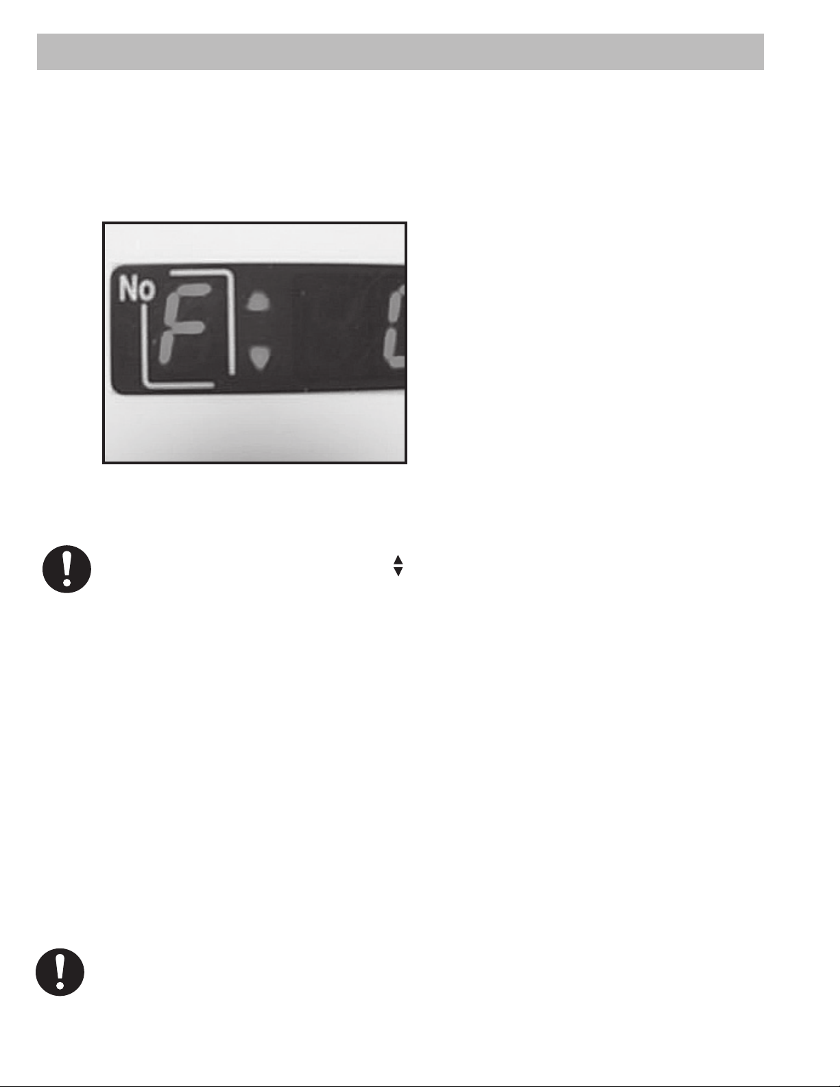
When using an FGV-X or FGV-XY force gauge, to program a force limit, press the “SET” button
on the front panel display. Note that the display “No” box shows “F ”. The “F” and the two arrows
indicate that it is ready to accept the force limits for both push and pull operation. (The programmed
force limits are the same for JOG and SING modes.) Use the “TIME/> to change digit position and
“RST/^” to increment each digit until the desired limit force is displayed.
Press the “TIME/<” button until no digits are blinking. This allows the user to select a negative sign by
pressing the “RST/^” button. IF there is no negative sign displayed,(-) the test stand force limit is programmed
as a compression force limit. IF the negative sign is displayed, the test stand force limit is programmed as a
tension force limit. Press “SET” to store the force limit in memory.
Setting Force limits w DFS force gauge:
If using the DFS force gauge, force limits are set on the force gauge using the DFS HI/LO comparator
feature. To stop the stand at a force limit using a DFS force gauge, you will need the FGS-50PCABLE
cable. This cable permits the DFS to send a signal to stop the stand’s movement when the DFS HI/
LO comparator force limits are activated.
The test stand will move in the left or right direction when the respective “PUSH” or “PULL” button is
selected. The stand will continue to move in the selected direction until one of the following events
occurs: “STOP” button is pushed, one of the manual limit switches are tripped, the emergency reset
button is pushed, or a force limit is reached.
9
Page 10
5.3 SING (Single Mode)
This mode of operation is ideal for completing one cycle between manual distance limits and/or force
limit. The initial starting direction can be either in the compression or tension direction depending on
whether the “PUSH” or “PULL” buttons are pressed.
If using a Shimpo FGV-X or FGV-XY force gauge, you may set a force limit on the test stand.
Front panel display indicating force
limit for both direction.
To program the force limit, press the “SET” button on the front panel display while in the “SING” mode. Note
that the display adjacent the “No” box shows “F ”. Use the “TIME” and “RST” buttons to select the desired
force limit. Press “SET” to store the force limit into memory.
TIME DELAY:
A time delay in seconds can be programmed between changes in direction by cycling the “TIME”
button through “0”, “1”, “2”, “3”, “4”, or “5”.
In this mode of operation the user can display length, speed or cycle count. Display length by pressing
the “LENGTH/SPEED” button until the LED adjacent “LENGTH” is illuminated. To display speed, push
the “LENGTH/SPEED” button until the LED adjacent “SPEED” is illuminated. Finally, to display Cycle
count, press the “LENGTH/SPEED” button until there are no LED’s illuminated. When the stand is
moving in the “pull” direction, the LED next to “SPEED A” is active. When the stand platform is moving
in the “push” direction the LED next to “SPEED B” is active.
The test stand will move left or right when the respective “PUSH” or “PULL” button is selected. The
stand will continue to move until one of the following events occurs: the “STOP” button is pushed,
one of the manual limit switches are tripped, the emergency reset button is pushed, or a force limit is
reached.
10
NOTE: An RS232C output is produced when using this mode of operation; see RS232C Output Section 6.0 for
details.
Page 11

5.4 CONT (Continuous Mode)
This mode of operation is ideal if the user wants the test stand to repeatedly cycle left or right
continuously or for a user-programmed number of times. The stand will start in either direction
depending on whether “PUSH” or “PULL” is selected.
Length, speed or cycle count can be displayed as described in 5.3 SING mode of operation.
To begin programming the test stand, press the “SET” key. The display will indicate a “C” in the
“No” box. The “C” designates that the digits programmed into the adjacent LED’s will determine the
number of cycles (number of times) a program will run. Using the “TIME/<” and the “RST/^” buttons
select the number of cycles you want the program to complete (0001-9999) or select four “0’s” if you
want the program to run continuously. Press “SET” to go to the next step.
The letter F appears in the LED’s in
the “No” box. This indicates that it is
ready to accept the upper force limit.
Use the “TIME/<” and “RST/^” buttons
to select the desired force limit.
NOTE: Pressing the “TIME/<”
button until no digits are blinking.
Allows the user to select a negative
sign by pressing the “RST/^”
button.
Set up for continuous cycle
With no negative sign displayed, the test stand platform is programmed to move downward. With the
negative sign displayed, the test stand platform will move upward. Press “SET” to store the upper
force limit in memory. The down arrow LED (F ) will light, indicating that the test stand is ready
to have its lower force limit programmed. Program the force limit using the “TIME/>” and “RST/^”
buttons.
Note: The upper force limit must be greater than the lower force limit (Fupper > Flower). Again
press “SET” to store the lower force limit into memory. You may delay the time between upward and
downward movements by selecting 0, 1, 2, 3, 4 or 5 seconds using the “TIME/>” button. You may
view distance traveled by pressing “LENGTH/SPEED” until the LED adjacent “LENGTH” is lit. Speed
can be displayed by pressing “LENGTH/SPEED” until the LED adjacent to the indicator “SPEED” is
lit. Finally, the number of cycles completed can be displayed by pressing “LENGTH/SPEED” until no
LED’s are lit.
NOTE: An RS232C output is produced when using this mode of operation; see RS232C Output
Section 6.0 for details.
11
Page 12

5.5 PROG (PROGRAM Mode)
Press the “MODE” key until the light emitting diode, LED, adjacent “PROG” is lit.
Length, speed or cycle count can be displayed as described in 5.3 SING mode of operation.
Cycles
To begin programming the test stand, press the “SET” key. The display will indicate a “C” in the
“No” box. The “C” designates that the digits programmed into the adjacent LED’s will determine the
number of cycles (number of times) a program will run. Using the “TIME/<” and the “RST/^” buttons
select the number of cycles you want the program to complete (0001-9999) or select four “0’s” if you
want the program to run continuously. Press “SET” to go to the next step.
Entering four zeros on cycle allows the test stand to perform the same programmed test continuously
until one of the three events occurs, the “STOP” button is pushed, emergency stop buttons is pressed,
or an overload condition is detected.
Force Limits
The display in “No” box now shows “F ”. The two arrows adjacent the “F” indicates that the test
stand is ready to accept compression or tension force limits. To program a force, use the “TIME/<”
and “RST/^” buttons to select a force value, and then press “SET”.
Home Position
The display in “No” box now shows “H”. The “H” designates the home position. Select “PUSH” or
“PULL” button to set the HOME position. Press “SET”. The test stand platform will automatically
move to the selected home direction, it will travel the set distance until the limit switch is activated.
Home position set to pull direction. Test
stand will look for the upper limit knob
Force “Zero”
The display in “No” box now shows “F”. The “F” designates the auto zero function. This function is
only available when using the Shimpo FGV-X or FGV-XY force gauges. Use the “TIME/<” and “RST/^”
buttons to program the “zero” force.
12
Page 13
NOTE: The recommended minimum zero force that the user should program into the test stand is 0.2% of
the full scale (rating of the force gauge), i.e. if using an FGV-50X or FGV-50XY force gauge, the programmed
“zero” force should be 0.1-lb (0.002 X 50 = 0.1).
If no force is programmed in this step and the display reads all zeros, the test stand will not
zero the distance and this feature is inoperative.
Press the “SET” button to move on to the next step. This is a very useful function that allows the
operator to reset the distance display and RS232 output data to zero once the force gauge senses
a force measurement.
Tare
The display in the “No” box now shows “t”. The “t” designates the tare function at “0” position. Select
“on” or “off” by using the “RST/^” button and press the “SET” button.
The tare function allows the user to use attachments on the force gauge and then set the force gauge display
to zero. This function is useful as some attachments weigh more than others and this function sets the
display to zero, provided that the attachment does not weigh more than 50% of the gauge’s capacity.
Note: Shimpo recommends taring not more than 20% of the gauge’s rated capacity; this
guarantees the availability of the force gauge’s full capacity.
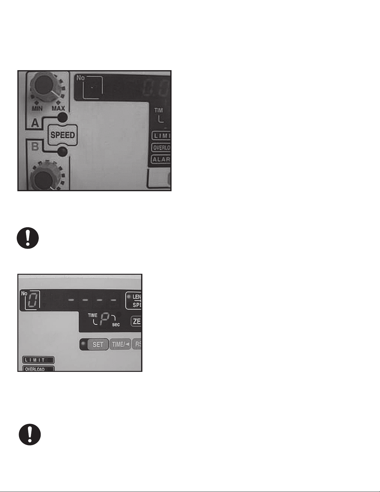
The display in the “No” box shows “0”, and the “LENGTH, SPEED, CYCLE” display shows “----”. The
“0” designates that the test stand begins each cycle from this position. Using the “PUSH” or “PULL”
and the “SPEED A” or “SPEED B” buttons, adjust the test stand to the position from which the force
gauge will begin force/distance tests. A time delay (pause) up to 5 seconds can be programmed
between programmed points. Use the “TIME/<” button to cycle through “0”, “1”, “2”, “3”, “4”, “5” or
“P”. If “P” is selected, the user must press the “PROG START “, key to restart the test stand program.
Position “0” is called the set point zero position, the test stand will return to this position at
the beginning of each cycle. The FGV-X or FGV-XY force gauge will also tell the test stand to
stop and return to the set point zero position if a programmed force limit is reached. If the force does
not attain a programmed force limit, the test stand will execute an entire cycle, then return to the
set point zero position and begin the next cycle. To delete an unwanted set position, press “RST/^”.
Then, press the “SET” key to move to the next programming step.
The force gauge plate will only go back to HOME position after all the cycles are completed. Each cycle
returns to the zero set point position
13
Page 14
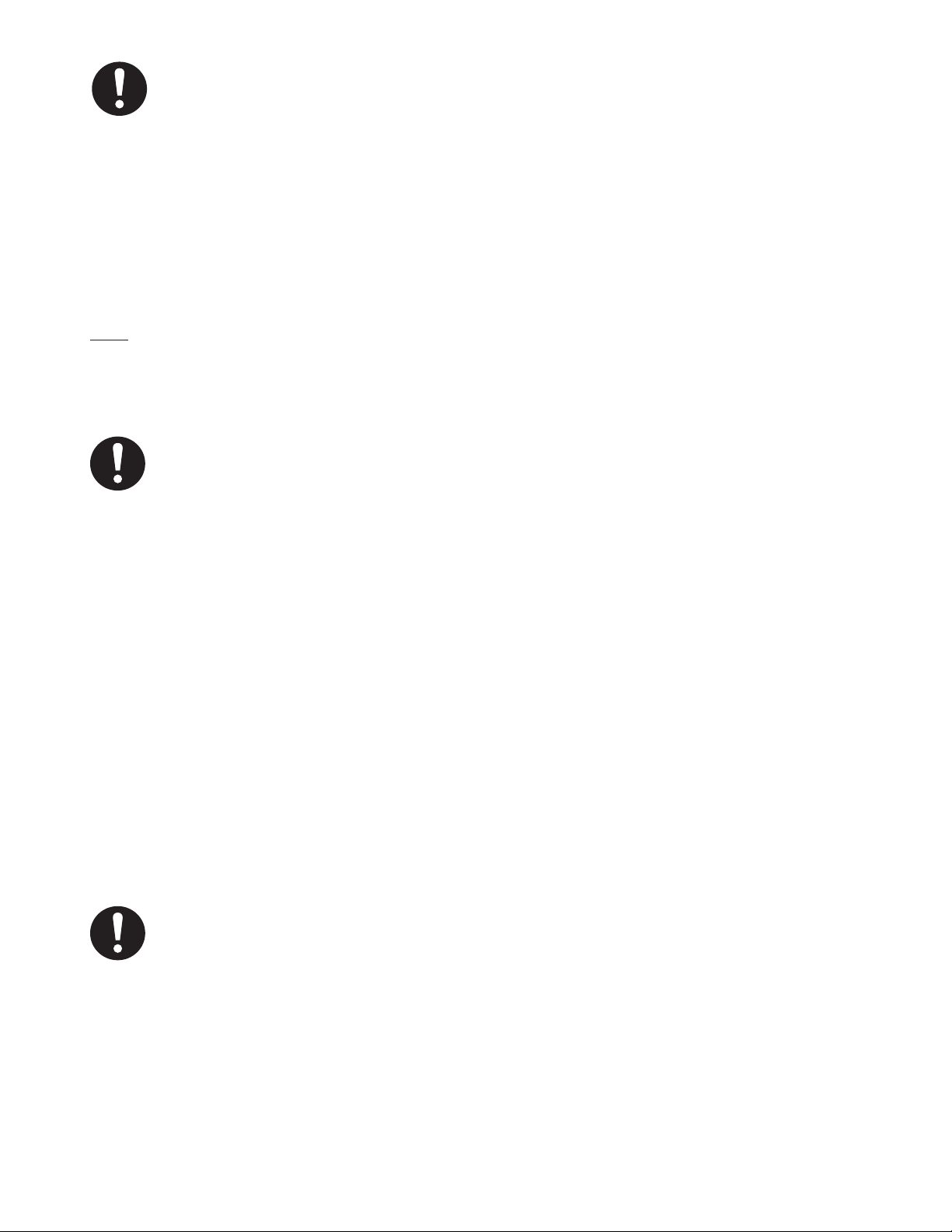
The display in the “No” box shows “1”, and the “LENGTH, SPEED, CYCLE” display shows “----”. The
“1” designates the next position of a cycle that the test stand will move to. This position is defi ned as
set point 1. Ensure that the correct LED indicator for “Speed A” or “Speed B” is illuminated so that
the test stand will travel at the intended speed. (see photo)
Using the “PUSH” or “PULL” button, move the
test stand force gauge platform to position 1.
Press the “SET” key.
(Note: If a programmed force limit is detected
by the force gauge, the test stand will not move
through the entire programmed distance and the
test stand will then return to set point zero.)
The display in the “No” box shows “2”, and the
“LENGTH, SPEED, CYCLE” display shows “---”. The “2” designates the next position of a cycle
that the test stand will move to. This position
is defi ned as set point 2. Using the “PUSH” or
Speed knob A and B. Desired speed can be
“PULL” and the “SPEED A” or “SPEED B” control
knobs move the force gauge to position 2
selected by pressing the “Speed” Button.
NOTE: If the programmed force limit is detected by the force gauge the test stand will not move the entire
programmed distance and the force gauge will return to set point zero.
Press the “SET” key.
Shown point zero ready to accept entry.
Use Push and Pull button to increment
and decrement value.
The display in “No” box shows “3”, and the “LENGTH,
SPEED, CYCLE” display shows “----”. Repeat these steps
outlined in the above paragraph up to a maximum of 5
points.
If no more steps are desired, press the “SET” key while
the “LENGTH, SPEED, CYCLE” display shows “----” to
fi nish programming the test stand.
14
It is not necessary to provide entries for all 5 set points. The test stand will work with one set point. If more
than two set points are entered and a change in the value of the second set point is required, re-enter the set
points for both entries. The distances (length) for the test stand program are accumulative, and dependent
on the previous set point. The distances (length) for the test stand program are accumulative, and
dependent on the previous set point.
Page 15

To Run Program:
Run the program by selecting “PROG START” on the display panel.
Clearing the previously stored program helps in eliminating program confl icts. To reset the program
memory, press and hold “RST/^” and then press “SET”. The display will read “CCCC”.
NOTE: An RS232C output is produced when using this mode of operation. See 6.0 RS232C Output
below for details.
Clearing the previously stored program helps
in eliminating program confl icts.
6.0 RS232C Output Format (using FGV-X Force Gauges)
“Cr” means carriage return
SING/CONT Mode
Plus Peak
Direction A: PULL
B: PULL
Minus Peak Distance
NOTE: Direction A: PULL, B: PUSH
“Cr” means carriage return or Enter
Data will be outputted when stand platform reaches a manual limit switch or a programmed
force limit.
15
Page 16

PROG Mode
Plus Peak Minus Peak Distance
Point
Number
Data will be sent when the test stand force gauge platform reaches every set position or if a force
load exceeds the force limit.
NOTE: If the auto zero function is selected, data will be outputted at the fi rst zero position, when the test
stand platform reaches every set position or if the force gauge exceeds a force limit.
“CR” means carriage return or Enter
7.0 Troubleshooting
Stand does not turn on: FIRST INSPECT all parts for physical interference
Check all electrical components:
• Check for correct AC power source, power cord condition, fuse condition, power switch
(should be “ON”), Emergency cut-off switch setting
• I Inspect test stand fi xtures and force gauge for overload conditions. To disengage
emergency switch, carefully press and turn clockwise.
The force gauge mounting platform does not move:
• Check manual limit knobs and adjust accordingly
• Check to see if the full travel range has already been achieved.
• Check test stand for correct operating mode.
• Check Emergency cut-off switch setting.
Force set points are not stopping the test stand (force gauge platform) movement
Check that communication exists between the force gauge and the test stand
Check that correct cable is fi rmly attached.
Check if the proper baud rate for communication is set from the force gauge. Required
baud rate is 19200 baud rate for FGV-X, FGV-XY. Communication with Shimpo DFS force
gauges bypasses the test stand to the PC when using the FGS-50PCABLE
16
Page 17

Display indicates “no_F” after power up
Check for proper force gauge cable (only for FGV-X and FGV-XY models).
Check for proper baud rate from the force gauge.
Reset the whole system, powering up in this particular order Force Gauge>Test Stand.
Initialization takes longer and a no_F display
indicates there is no communication established
between the test stand and the force gauge.
Shimpo DFS models transfer data directly
using the FGS-50PCABLE. Length/
Distance of the test is programmed in
the test stand. When using Shimpo DFS
force gauge, “MANU” and “SING” (modes)
function the same.
Limit switch not stopping the test stand/force gauge from moving Check if the limit switch shoe
behind the knob has been turned in the wrong position. (See photos for proper orientation and
installation).
Actuator limit switch rollers should hit
this side of the shoe limit switch.
Insert the washer before the knob.
The limit switch shoe has a lip guide
preventing it from spinning. Orient
the Limit switch shoe properly before
installation.
17
Page 18

Getting incorrect distances during a test
Re-enter all the test points distances (Remember that the distance is dependent on
previous set points and set points are accumulative).
Check if a previous or incorrect force limit is set in memory
RS-232 output not working correctly
Check that proper cables are selected and attached to the force gauge test stand and PC.
Cable DESCRIPTION
FGV-FGS250P
FGS-50PCABLE DFS cable for transferring data directly from the Shimpo DFS force gauge to PC.
FGV-RS232 Interface cable for data output from test stand to PC. (for FGV-X and FGV-XY Models)
FGS-ANALOG Analog output cable for data acquisition requirements. (provided with stand)
Communication cable between the test stand and the force gauge.
(for FGV-X and FGV-XY Models) (provided with stand)
8.0 Test Stand Specifi cations
Model
Capacity
Travel speed
Stroke
Repetition number
Operation mode
Output
signal
Input
Horizontal attachment
table-height range
Horizontal table
dimensions
Operating Temperature
Power supply
Weight
Standard parts
Options
Analog
voltage
RS-232C
Overload
input
FGS-100PXL FGS-100PXH
Low speed High speed
110 lbs (500N,50kgf)
0.19 - 4.72 inch/min
(5-120mm/min)
2 types of speed switch
5.51in (140 mm) with mechanical backlash 0.2 -
Manual, Jog, Single, Continuous cycling,
Program mode
Output the displacement of the stand 10mV/mm
MAX: ±1.4V
19200 Baud rate
Stops operation due to force overload on Shimpo
DFS or FGV-X or FGV-XY
0 - 1.38 inch (0 - 35mm)
5.90 X 5.70 inch (150×145mm)
0~45(non condensing)
AC115V (±10%)
40 lbs (18 kg)
120Vac socket for force gauge, FGS-250P cable
for FGV-X and FGV-XY, FGS-ANALOG cable for
test stand analog output.
FG-HORIZ-ADAP: Horizontal mounting block for
grip/fixtures. FG data cables, digital and
mechanical force gauges, data collection
0.79 - 19.69 inch/min
(20 - 500mm/min)
0.5 mm)
0 -9999
software
18
Page 19

9.0 Dimensions and Drawings
Test Stand Dimensions
Horizontal Table
Force Gauge Mounting Plate
19
Page 20

Warranty
LIMITED EXPRESS WARRANTY
Shimpo Instruments warrants, to the original purchase of new products only, that this product shall be
free from defects in workmanship and materials under normal use and proper maintenance for one year
from the date of original purchase. This warranty shall not be effective if the product has been subject to
overload, misuse, negligence, or accident or if the product has been repaired or altered outside of Shimpo
Instruments authorized control in any respect which in Shimpo Instruments judgment, adversely affects its
condition or operation.
DISCLAIMER OR ALL OTHER WARRANTS
The foregoing warranty constitutes the SOLE AND EXCLUSIVE WARRANTY, and Shimpo Instruments
hereby disclaim all other warranties, expressed, statutory or implied, applicable to the product, including,
but not limited to all implied warranties of merchantability and fi tness.
LIMITATION OF REMEDY
Under this warranty, Shimpo Instruments’ SOLE OBLIGATION SHALL BE TO REPAIR the defective product
or part, at Shimpo Instruments’ option. Shimpo Instruments reserves the right to satisfy warranty obligation
in full by reimbursing Buyer for all payment made to Shimpo Instruments, whereupon, title shall pass to
Shimpo Instruments upon acceptance of return goods. To obtain warranty service, Purchaser must obtain
Shimpo Instruments’ authorization before returning the product, properly repackaged, freight pre-paid to
Shimpo Instruments.
INDEMNIFICATION & LIMITATION OF DAMAGES
Buyer agrees to indemnify and hld Shimpo Instruments harmless from and against all claims and damages
imposed upon or incurred arising, directly or indirectly, from Buyer’s failure to perform or satisfy any of the
terms described herein. In no event shall Shimpo Instruments be liable for injuries of any nature involving
the product, including incidental or consequential damages to person or property, any economic loss or
loss of use.
MERGER CLAUSE
Any statements made by the Seller’s representative do not constitute warranties except to the extent that they
also appear in writing. This writing constitutes the entire and fi nal expression of the parties’ agreement.
Copyright © Nidec-Shimpo America Corporation 2001. All right reserved. Product specifi cations are subject
to change without notice.
20
 Loading...