

Page 1
Series Digital Force Gauges
Models FGE-0.5X - 100X
Models FGV-0.5X - 100X
INSTRUCTION MANUINSTRUCTION MANU
INSTRUCTION MANU
INSTRUCTION MANUINSTRUCTION MANU
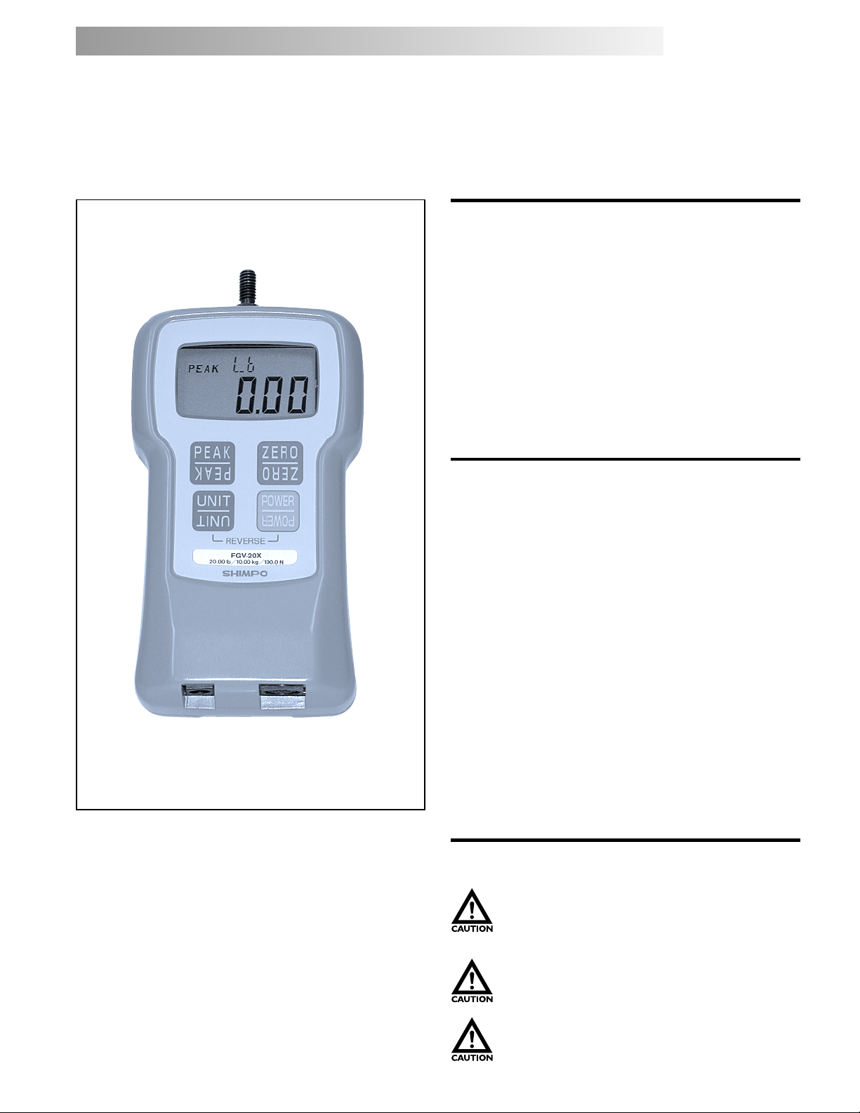
Congratulations on your purchase of a Shimpo FGE/V-X
series digital force gauge. We trust you will enjoy many
years of professional results from your Shimpo product.
Please read the entire instruction manual thoroughly
before initial set-up and operation; the information
contained herein will aid you in operating your Shimpo
digital force gauge safely and with excellent results.
If you have any questions regarding our product(s), call
your local Shimpo representative or contact Shimpo
Instruments directly for assistance.
ALAL
AL
ALAL
Inspection/Standard Accessories
If upon delivery shipping damage is detected, do not
operate the unit. Notify shipping carrier immediately
for damage claim instructions. Refer to nameplate and
record serial number for future reference. Items included
with the DART are:
• (1) Carrying case
• (1) Standard adapter set (hook, chisel, flat head,
notched head, cone head, extension rod)
• (1) Inch adapter (metric - English thread)
• (1) Hanger
• (1) RS-232C cable (FGV-X series only)
• (1) AC charger/adapter
Features and Benefits
Shimpo’s DART series digital force gauges offer many
features and benefits, including:
• 1,000 Hz update rate for capturing highest peaks
• Aluminum construction provides exceptional
durability
• An ergonomically designed digital instrument to
fit perfectly in the palm of your hand
• Single touch, measure force in lb, Kg and N (oz/gram
for 0.5X, 1X,2X) engineering units
• When gauge is placed on a test stand or if the
hanger is used, display may be reversed with push
buttons so that it can be read right side up.
• High accuracy ( ±0.2% F.S. ) is ideal for QC
inspection and process control
• RS-232C and Analog output (FGV-X series only)
• Inch adapter for converting our Metric thread to
an English thread. If your fixtures are English
threaded, please use this adapter.
Safety Precautions
Do not operate or store instrument in the
following places: explosive areas; near water, oil,
dust, or chemicals; areas where temperature is
above 104°F (40°C).
When not in use, place gauge back in its case to
prevent damage due to accidental drop etc. With
a little care you can have an instrument that will
provide service for many years.
Do not disassemble or repair unit while in
operation.
1
Page 2
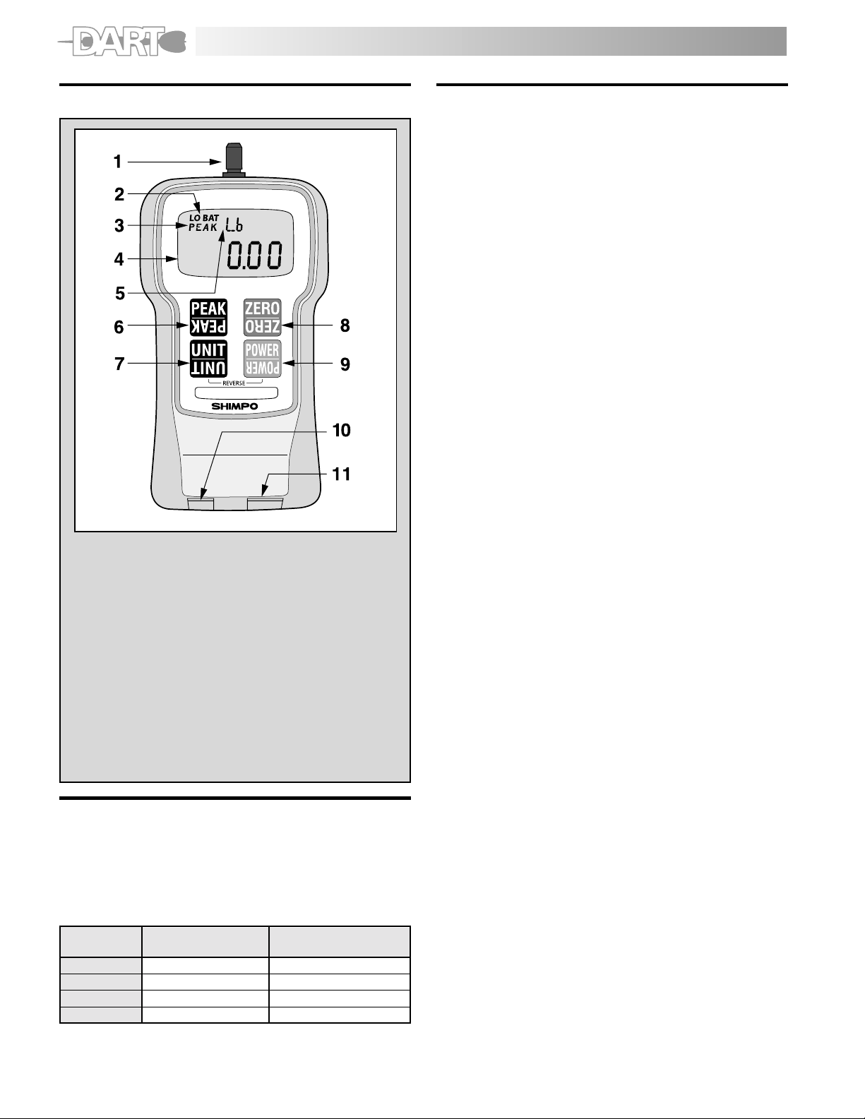
Physical Features
Operation
1. Charge the batteries for approximately 18 hours
before using the gauge (Batteries come discharged
from the factory). The BAT indicator is on when
batteries are charging, off when the batteries are
fully charged.
2. Hand tighten appropriate attachment to unit’s
measuring shaft (do not use a wrench or any other
device to tighten the attachment).
3. Press POWER and release. The unit will display model
name in small display and capacity in main display
and then will show some zeros with the last one or
two digits changing to some random numbers. Also
the unit of measurement (lb (oz), Kg (g) or N) will
appear above the digits and stay as long as the
instrument is on.
Change Display Units
To change the display units, just press UNIT and the units
will change every time the button is pressed.
lb ! oz (0.5X, 1X, 2X models only) ! N ! Kg (g) !
Reverse the Display
If unit is used with the hanger or mounted on a test stand
and the display must be reversed, follow this procedure:
NO. DESIGNATION
1. Sensor Shaft
2. Low Battery Indicator
3. Peak Indicator
4. Main Display
5. Small Display
6. Peak Button
7. Unit Button
8. Tare and Zero Button
9. Power (ON, OFF) switch
10. AC Adapter Port
11. Data Output Port
Factory Setting
The FGE/V-X will revert to factory setting when the gauge
is first powered on. Consult the “Function Setting”
section to customize these default settings.
The following chart reflects the default settings as
programmed by the factory:
FUNCTIONFUNCTION
FUNCTION
FUNCTIONFUNCTION
NUMBERNUMBER
NUMBER
NUMBERNUMBER
f01 Plus or Minus sign 0001 (plus for compression)
f02 Display update time 3 (3 times/sec)
f03 Auto power off 10 (min)
f04 Baud rate of RS-232C 2400 (bps)
DESCRIPTIONDESCRIPTION
DESCRIPTION
DESCRIPTIONDESCRIPTION
DEFDEF
DEF
DEFDEF
AA
ULUL
T FT F
ACTORYACTORY
A
UL
T F
ACTORY
AA
ULUL
T FT F
ACTORYACTORY
SETSET
TINGTING
SET
TING
SETSET
TINGTING
1. Press POWER and hold it; display will go blank.
2. Press and hold UNIT.
3. Release POWER while you are still holding UNIT;
display is still blank.
4. Press POWER once more and release it while still holding
UNIT. At this point you should see the display reversed.
5. Release UNIT; the display stays in that mode.
To go back to normal mode repeat steps 1 through 5.
Select Average or Peak
If you want to measure force in real time (average) the
display will show only the digits and units of the force
being measured. If you want to measure “peak” force:
1. Press PEAK; the word PEAK will appear in the upper
left corner of the display. (If you need a minus peak,
press PEAK again.)
2. The display will freeze after capturing the peak force.
3. Press ZERO to cancel previous peak and continue with
your tests.
If you want to go back to average mode press PEAK again.
The word PEAK will disappear from the display.
NOTE: It is very important that you measure forces
(tension or compression) that are in line with the
measuring shaft and not at any angle (see fig. 1). Failure
to observe this directive will damage the instrument. Also,
after the gauge is positioned and ready to take a
measurement (with the proper attachment in place) tare
the unit by pressing ZERO. To clear the display for another
measurement (in PEAK mode), press ZERO.
2
Page 3
Tension Measurement
To measure tensile force, use the hook attachment. The
display will show the force measured and a minus sign () will appear on the left of the display (to the left of the
digits).
NOTE: To display no sign (plus) for tensile force, consult
the “Function Setting” section.
Compression Measurement
To measure compression force, use the flat head
attachment. No sign will appear on the left of the display
during a compression measurement.
NOTE: To display minus sign (-) for compression force,
consult the “Function Setting” section.
Low Battery
When battery charge is low, LO BAT will appear on the
display indicating the batteries need to be charged.
Charging time of fully depleted batteries is approximately
18 hours when the unit is off. The adapter/charger
automatically shuts off when the battery is at full charge
to protect the battery.
Note: The adapter/charger can be used to power the unit
during battery charging, but will lengthen charging time.
External Device Communications
When operated with the appropriate output cable, the
FGV-X offers output capabilities.
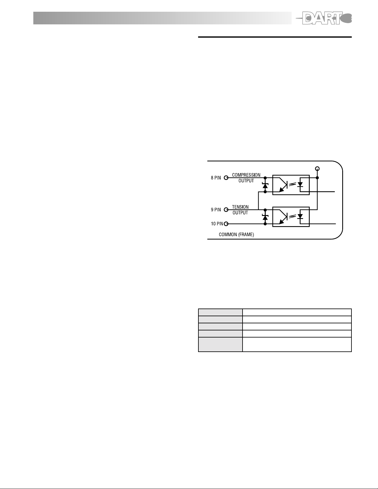
Overload
Even though each model is able to withstand an overload
of 200% of its rated capacity, caution should be exercised
that this does not happen, otherwise the sensor will be
damaged. To protect the gauge and/or the sample under
test when a motorized stand or some other device is
used in conjunction with the gauge, two overload output
OC NPN transistors are available to be used to disconnect
power when the overload condition reaches 120% of
the gauge’s rated capacity. One transistor is for tension
and the other for compression. See figure 2.
Auto Power Off
If the gauge is on and there is no activity for 10 minutes,
the unit automatically powers off to conserve battery
charge. PWR appears above the display digits to notify
that there is 1 minute before power off. If the adapter/
charger is powering the gauge, auto power off function
becomes inactive.
NOTE: To modify the auto power off function, consult
the “Function Setting” section.
Tracking Function
A tracking function has been introduced to check and
compensate for temperature drift. When measuring very
minute forces (a few ounces or grams) and at a very
slow rate, you may want to turn off the tracking function.
To turn the tracking function off, follow the steps below:
1. Turn POWER off.
2. Press PEAK and UNIT switches simultaneously and
hold, then press and release POWER (If tracking
function was on, the display will show TRK OFF
momentarily)
3. Release PEAK and UNIT.
The tracking function is now off. Repeat above steps to
turn it on. The gauge will display TRK SET when turned
on. It is a good idea to have this function on at all the
times unless it is absolutely necessary to cancel it.
Fig. 2
Analog Output
An analog output signal is available for recording
purposes. The amplitude of this signal is ± 1 VDC. The
voltage is positive when compression testing is performed
and negative for tension. The signal characteristics are
as follows:
AmplitudeAmplitude
Amplitude ± 1 VDC
AmplitudeAmplitude
Generated byGenerated by
Generated by 12-bit D/A converter
Generated byGenerated by
Signal updateSignal update
Signal update 100 times/sec (update every 10 msec)
Signal updateSignal update
Load impedanceLoad impedance
Load impedance 10 KW minimum
Load impedanceLoad impedance
Connector pinsConnector pins
Connector pins Pin #1 signal output (analog)
Connector pinsConnector pins
Pin #2 GND (analog)
(see Fig.3 & Table 1)
NOTE: When the zero switch is pressed to tare the gauge
the analog output goes to 0V automatically.
3
Page 4

RS-232C Port
An important feature of the FGV-X family of gauges is
the RS232C communications port. Data and commands
can be linked to a PC or any other device responding to
RS232C signals for storage or further analysis. Table 1
(below) describes the function of each pin of the
connector (HR12-10RC-10SDL) shown in Fig. 3.
PIN#PIN#
PIN# DESCRIPTION
PIN#PIN#
11
1 Analog signal output
11
22
2 Analog GND
22
33
3 Receive data (input)
33
44
4 Digital GND
44
55
5 Communication enable
55
66
6 Transmit data (output)
66
77
7 No connection
77
88
8 Compression overload output
88
99
9 Tension overload output
99
1010
10 Frame GND
1010
Table 1
Figure 3
(HR12-10RC-10SDL), HIROSE
RS232C Output SpecificationsRS232C Output Specifications
RS232C Output Specifications
RS232C Output SpecificationsRS232C Output Specifications
Baud rateBaud rate
Baud rate 2400, 4800, 9600, 19200 bps (selectable)
Baud rateBaud rate
Data lengthData length
Data length 8 bits
Data lengthData length
PP
arityarity
P
arity None
PP
arityarity
Stop bitStop bit
Stop bit One
Stop bitStop bit
Commands/Responses
The FGV-X series of force gauges has the ability to
recognize and respond to various commands from
outside peripherals. If for instance the gauge receives a
legitimate command from a PC, it will respond by sending
back the same code indicating to the PC that the
command was recognized. If for example the command
is a request for average data output, it will send the
data and the code NA etc. If the gauge recognizes an
error while it is receiving a command, an error symbol is
transmitted back to the PC indicating the exact nature
of the error.
Commands to FGV-X Gauge
AAcr Tare
ABcr Stop output
ACcr Change to peak mode
ADcr Change to average mode
AEcr Peak reset
AFcr Change units to Kg (g)
AGcr Change units to N
AHcr Change units to lb (oz)
BAcr Data output request (single reading)
BBcr Continuous data output request (10 times/sec)
BB1cr Continuous data output request (20 times/sec)
BB2cr Continuous data output request (50 times/sec)
BB3cr Continuous data output request (100 times sec)
BCcr Model name confirmation request
BDcr Units confirmation request
BEcr Peak data output request
BFcr Minus Peak data output request
cr (cr: carrige return)
Response from FGV-X gauge
NA""""""cr Average data output
NB""""""cr Peak data output
4-digit number with decimal point
sign (+ or –)
NE""cr Model number
02 = FGV-0.5X
03 = FGV-1X
04 = FGV-2X
05 = FGV-5X
06 = FGV-10X
07 = FGV-20X
08 = FGV-50X
09 = FGV-100X
NH"cr Unit
0 = N
1 = Kg (g)
2 = lb (oz)
Error Symbols
OBcr Command error
OEcr Parity error
OFcr Format error
OGcr Summing error
OHcr Overrun error
4
Page 5

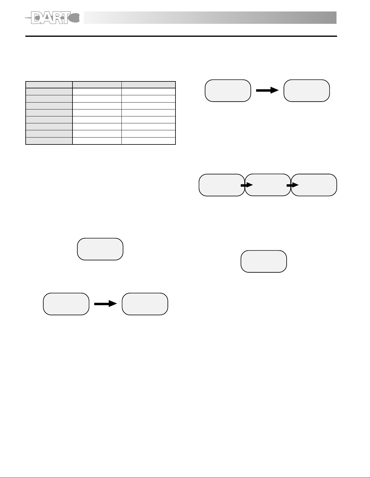
Function Setting
The FGE/V-X will default to certain parameters when power is turned OFF and ON. To access the function setting:
1. Press and hold the ZERO button.
2. Press and release the POWER button.
3. Each time the PEAK button is pressed, the FGE/V-X will scroll through each of the functions.
4. Press the ZERO button to exit.
OFF
Press and hold ZE RO butt on. Pr ess and r el ea se the PO WE R button. -> See Fi g. 3
Plus or minus si gn
F01
0001
PEAK
Displ ay updat e time
**
F02
3
PEAK
Auto power off
PEAK
Baud rate of
RS232C
PEAK
Plus or minus si gn
**Note: In function 2 , the num b ers sign ify as follows.
1; 1 time/sec, 2; 2 times/sec, 3; 3 times/sec, 5; 5 times/sec, 10; 10 times/sec, 20; 20 times/sec
F03
10
F04
2400
UNIT
UNIT
UNIT
UNIT
UNIT UNIT
F01
-0001
Minus Plus
UNIT
F02
5
UNIT
F03
OFF
UNIT UNITUNITUNIT
F04
4800
F02
F03
F04
9600
F01
0001
10
10
UNIT
UNIT
F02
F04
19200
UNIT
20
F02
F04
2400
UNIT UNIT
1
F02
2
UNIT
F02
3
ZERO
Data was memorized
Data was memoried.
5
Page 6
Calibration
1. A secure calibration stand to mount a force gauge
upside-dawn.
2. The appropriate calibration weight for your force
gauge. (Metric only!)
9. Press ZERO to zero calibrate. Wait approx. 17
seconds. The display will change to show PEK after
blinking SCN. Do not press any other switches or
move the sensing shaft during calibration.
MODELMODEL
MODEL
MODELMODEL
FGE/V-0.5X 02 200 g
FGE/V-1X 03 500g
FGE/V-2X 04 1Kg
FGE/V-5X 05 2Kg
FGE/v-10X 06 5Kg
FGE/V-20X 07 10Kg
FGE/v-50X 08 20Kg
FGE/V-100X 09 50Kg
3. Turn POWER off.
4. Mount the force gauge upside down on the
calibration stand.
5. Attach the fixture on the sensing shaft of the force
gauge, carefully threading it finger tight.
6. Press and hold the UNIT, PEAK and ZERO switches.
7. Press and release the POWER switch (while continuing
to press UNIT, PEAK and ZERO) until the smaller
characters at the top of area of the display show
CAL. Release the UNIT, PEAK and ZERO switches. The
force gauge is now in calibration mode.
CODECODE
CODE
CODECODE
WEIGHTWEIGHT
WEIGHT
WEIGHTWEIGHT
CAL
-00-
8. Press the UNIT switch. The display will show ZER after
blinking SCN for 10 seconds. The force gauge is now
ready for zero point calibration.
“SCN”
88888
10. Hang the calibration weight on the hook and
stabilize; the larger characters on the display will
change. The force gauge is now ready for full-scale
calibration.
11. Press the PEAK switch to begin full scale calibration.
Display blink SCN. Do not press any other keys or
touch the weight during calibration. After approx.
17 seconds the display blinks END, then after approx.
5 seconds the display blinks OK.
“SCN”
88888
12. If calibration was successful, the display will show
OK momentarily (see above picture.). Press the UNIT
switch, then automatically power off.
13. If calibration was unsuccessful, the display will show
ERR. Remove the calibration weight, then press UNIT
switch. Repeat the procedure 6-9.
“End”
88888
PEK
88888
“oK”
88888
Err
88888
“SCN”
-00-
6
ZER
88888
Page 7

Troubleshooting
The following are general checkpoints; please call your local Shimpo representative or contact Shimpo Instruments
directly for further assistance.
The force gauge does not come on:
• Check all electrical components (power source, charged battery or AC adaptor connected)
The stand does recognize the RS232 output/input:
• Check all connections between the test stand and the force gauge and/or computer
Error codes are displayed:
• Turn unit off, then back on. If error codes are still displayed, see table below:
Small display
Small display Condition
Small displaySmal l display
Condition Action
ConditionCondition
Action
ActionAction
OVM
OVP
OV+
OV-
ERR
- 3 -
ERR
- 4 -
Dimensions
Minus side overload condition - possible load cell damage
Remove exces si ve load; i f the display doe s not return to normal operati on,
send unit in for repair
Plus side overload condition - possible load cell damage
The loa d exceeds 120% of its ca pacity Remove excess ive load
EEPROM reading error
Turn off, then turn on again. If the display does not return to normal operation,
send unit in for repair.
EEPROM wr iting error
7
Page 8

Specifications
GE-X and FGV-X DART SERIES SPECIFICATIONS
F
FGE-FGE-
X ModelX Model
FGE-
X Model
FGE-FGE-
X ModelX Model
FGVFGV
--
X ModelX Model
FGV
-
X Model
FGVFGV
--
X ModelX Model
CapacityCapacity
Capacity 0.5 lb (8 oz) 1 lb (16 oz) 2 lb (32 oz) 5 lb 10 lb 20 lb 50 lb 100 lb
CapacityCapacity
RR
esolutionesolution
R
esolution 0.001 lb (0.01 oz) 0.001 lb (0.01 oz) 0.001 lb (0.01 oz) 0.001 lb 0.01 lb 0.01 lb 0.01 lb 0.1 lb
RR
esolutionesolution
AccuracyAccuracy
Accuracy ±0.2% f.s.
AccuracyAccuracy
DisplayDisplay
Display 4-Digit LCD, 12mm high. Reversible by the push of a button. Minus sign for tension.
DisplayDisplay
Display UpdateDisplay Update
Display Update 0.05, 0.1, 0.2, 0.3, 0.5, 1 sec
Display UpdateDisplay Update
Sampling RSampling R
Sampling R
Sampling RSampling R
OverloadOverload
Overload 200% of f.s.
OverloadOverload
PP
P
PP
Output (FGVOutput (FGV
Output (FGV
Output (FGVOutput (FGV
Auto PAuto P
Auto P
Auto PAuto P
BatterBatter
Batter
BatterBatter
RR
R
RR
TT
emperatureemperature
T
emperature 32° - 104°F (0° - 40°C)
TT
emperatureemperature
DimensionsDimensions
Dimensions 5.1” L x 2.9” W x 1.5” H (130 mm x 75 mm x 38 mm)
DimensionsDimensions
WW
W
WW
Standard AccessoriesStandard Accessories
Standard Accessories AC adapter/charger, carrying case, hook, chisel, flat head, notched head, hanger, cone head, extension rod, inch adapter,
Standard AccessoriesStandard Accessories
ApprovalsApprovals
Approvals CE approved
ApprovalsApprovals
ateate
ate 1000 times per second
ateate
owerower
ower Rechargeable Ni-Cad battery or AC through adapter/charger
owerower
only)only)
only) Analog: ±1VDC (through a 12 bit D/A converter)
only)only)
ower Shut-Offower Shut-Off
ower Shut-Off Yes (not active if adapter/charge is in use)
ower Shut-Offower Shut-Off
y Chargey Charge
y Charge 12 hours (when fully charged)
y Chargey Charge
echarge Timeecharge Time
echarge Time Approximately 18 hours when fully discharged
echarge Timeecharge Time
eighteight
eight 1 lb (450 g)
eighteight
FGE-0.5XFGE-0.5X
FGE-0.5X
FGE-0.5XFGE-0.5X
FGVFGV
-0.5X-0.5X
FGV
-0.5X
FGVFGV
-0.5X-0.5X
200.0 g 500.0 g 1,000 g 2.000 Kg 5.000 Kg 10.00 Kg 20.00 Kg 50.00 Kg
2.000 N 5.000 N 10.00 N 20.00 N 50.00 N 100.0 N 200.0 N 500.0 N
0.1 g 0.1 g 1 g 0.001 kg 0.001 kg 0.01 kg 0.01 kg 0.01 kg
0.001 N 0.001 N 0.01 N 0.01 N 0.01 N 0.1 N 0.1 N 0.1 N
RS232C: Baud rate (19200, 9600, 4800, 2400 bps selectable), commands control
FGV-232CABLE (FGV series only)
FGE-1XFGE-1X
FGE-1X
FGE-1XFGE-1X
FGVFGV
-1X-1X
FGV
-1X
FGVFGV
-1X-1X
FGE-2XFGE-2X
FGE-2X
FGE-2XFGE-2X
FGVFGV
-2X-2X
FGV
-2X
FGVFGV
-2X-2X
FGE-5XFGE-5X
FGE-5X
FGE-5XFGE-5X
FGVFGV
-5X-5X
FGV
-5X
FGVFGV
-5X-5X
FGE-10XFGE-10X
FGE-10X
FGE-10XFGE-10X
FGVFGV
-10X-10X
FGV
-10X
FGVFGV
-10X-10X
FGE-20XFGE-20X
FGE-20X
FGE-20XFGE-20X
FGVFGV
-20X-20X
FGV
-20X
FGVFGV
-20X-20X
FGE-50XFGE-50X
FGE-50X
FGE-50XFGE-50X
FGVFGV
-50X-50X
FGV
-50X
FGVFGV
-50X-50X
FGE-100XFGE-100X
FGE-100X
FGE-100XFGE-100X
FGVFGV
FGV
FGVFGV
-100X-100X
-100X
-100X-100X
8
 Loading...