

Page 1

6.0 WARRANTY
Electromatic Equipment Co., Inc. (Electromatic) warrants to the original purchaser
that this product is of merchantable quality and confirms in kind and quality with the
descriptions and specifications thereof. Product failure or malfunction arising out of
any defect in workmanship or material in the product existing at the time of delivery
thereof which manifests itself within one year from the sale of such product, shall be
remedied by repair or replacement of such product, at Electromatic’s option, except
where unauthorized repair, disassembly, tampering, abuse or misapplication has
taken place, as determined by Electromatic. All returns for warranty or non-warranty
repairs and/or replacement must be authorized by Electromatic, in advance, with all
repacking and shipping expenses to the address below to be borne by the
purchaser.
THE FOREGOING WARRANTY’S IN LIEU OF ALL OTHER WARRANTIES,
EXPRESSED OR IMPLIED, INCLUDING BUT NOT LIMITED TO, THE
WARRANTY OF MERCHANTABILITY AND FITNESS FOR ANY PARTICULAR
PURPOSE OR APPLICATION. ELECTROMATIC SHALL NOT BE RESPONSIBLE
NOR LIABLE FOR ANY CONSEQUENTIAL DAMAGE, OF ANY KIND OR
NATURE, RESULTING FROM THE USE OF SUPPLIED EQUIPMENT, WHETHER
SUCH DAMAGE OCCURS OR IS DISCOVERED BEFORE, UPON OR AFTER
REPLACEMENT OR REPAIR, AND WHETHER OR NOT SUCH DAMAGE IS
CAUSED BY MANUFACTURER’S OR SUPPLIER’S NEGLIGENCE WITHIN ONE
YEAR FROM INVOICE DATE.
Some State jurisdictions or States do not allow the exclusion or limitation of
incidental or consequential damages, so the above limitation may not apply to you.
The duration of any implied warranty, including, without limitation, fitness for any
particular purpose and merchantability with respect to this product, is limited to the
duration of the foregoing warranty. Some states do not allow limitations on how long
an implied warranty lasts but, not withstanding, this warranty, in the absence of such
limitations, shall extend for one year from the date of invoice.
Electromatic Equipment Co., Inc.
600 Oakland Ave. Cedarhurst, NY 11516 - USA
Tel: 1-800-645-7330 / Tel: 516-295-4300 / Fax: 516-295-4399
Every precaution has been taken in the preparation of this manual. Electromatic assumes no
responsibility for errors or omissions. Neither is any liability assumed for damages resulting
from the use of information contained herein. Any brand or product names mentioned herein
are used for identification purposes only, and are trademarks or registered trademarks of their
respective holders.
CONTENTS
1.0 BASIC DESCRIPTION …………………………………………… 2
1.1 Recommended Use
1.2 Basic Characteristics
1.3 Care Guidelines
2.0 PCFE DESCRIPTION …………………………………………… 4
3.0 OLED DISPLAY …………………………………………… 6
3.1 Language Mode - Keypad Function
3.2 Unit Mode - Keypad Function
3.3 Date Mode - Keypad Function:
3.4 Trac Mode
3.5 Peak Mode
3.6 Set Mode
3.7 Set Mode - Torque & Angle
3.8 Set Mode – Torque
3.9 Set Mode - Just Move Preset
3.10 Just Move
3.11 Just Angle
3.12 Preset Mode
3.13 Preset Mode - Keypad Function
3.14 Recall Mode
3.15 Recall Mode - Keypad Function
3.16 Upload Mode
3.17 Clear Mode
4.0 WRENCH CALIBRATION …………………………………………… 12
4.1 Calibrate Mode
4.2 Torque and Angle Calibration
4.3 Communication to PCFE
4.4 Communication using USB Cable
4.5 Wrench Data Transfer Protocol
5.0 PCFE INSTRUCTIONS …………………………………………… 16
5.1 Changing the Password
5.2 Language
5.3 PCFE Window
5.4 Set a Preset using the PCFE
5.5 Bottom Section of PCFE
6.0 WARRANTY …………………………………………… 20
Electromatic Equipment Co., Inc.
-20-
Electromatic Equipment Co., Inc.
-1-
Page 2
1.0 BASIC DESCRIPTION
These Electronic Torque Tools are "State of the Art" devices, With Intelligent
Technology, Organic LED display (OLED). They are Menu Driven with Total
Tracability. Demonstrated to have better than 1% Accuracy. They are Simple to Set
and Calibrate and come complete with ISO 6789-2003 Certification.
These Torque Tools are, Hand-held Torque Measuring Instruments which provide
Precision Accuracy, They have High Repeatability. Presets can be set to provide the
user with Visual & Audio Signal's during Torque measurements. Supplied with visual
Low Battery Indicator. Use the wrench's for Preset Value Approach, Fastener
Overload, Range Overload, Maximum Mechanical Overload.
1.1 Recommended Use
The Electronic Torque Tools are specifically designed for use in all Industrial
Sectors and Applications where High Accuracy and Repeatability combined with a
Complete Torque Data Management & Control System are Standard Requirements.
1.2 Basic Characteristics
- Accuracy:Right hand side torque = 1%, Left hand side = 1% of Actual Reading
- Resolution: 0.05 to 50Nm & 0.1 to 1000Nm
- Alarms:Preset Value Approach, Fastener Overload, Range Overload,
Mechanical Overload, Low Battery, Memory Full.
- Memory Capacity: 2094 Values
- Battery Life:Sleep Mode 5,000 Hrs, Operational Mode 160 Hrs.
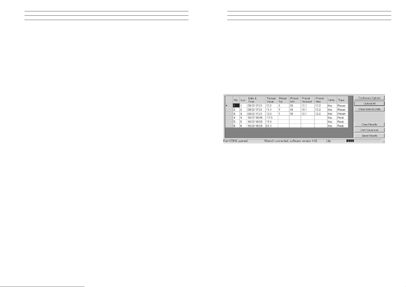
5.5 Bottom Section of PCFE
The lower section of the PCFE allows the user to view stored results from the
wrench. These results can then be saved as an Excel file for further analysis and to
offer the user complete traceability of their torque measurements.
Each row will display the following; Time and date of Torque operation, Torque
value and units, If it's a Preset result then the Minimum and Maximum tolerances
are displayed along with the nominal setting.
The "Type" Column will display the function that was been used for the Torque
operation, In the Example below you can see Peak and Preset.
Continuous Upload: When the wrench is connected to the PCFE and this is
selected then the user can take reading's and by pressing
confirm on the wrench the result will be automatically up
dated to the PCFE
Upload All: Once the wrench is connected to the PCFE, selecting this
option will upload all the wrench stored measurements to the
PCFE
Clear Wrench Data: Selecting this option will clear the stored results from the
wrench memory
Clear Results: Selecting this button on the PCFE will clear the displayed
PCFE results
Unit Conversion: Selecting this button allows the user to convert the displayed
PCFE readings between Nm, cNm, lbft, lbins, mkg and cmkg
Electromatic Equipment Co., Inc.
-2-
Electromatic Equipment Co., Inc.
-19-
Page 3
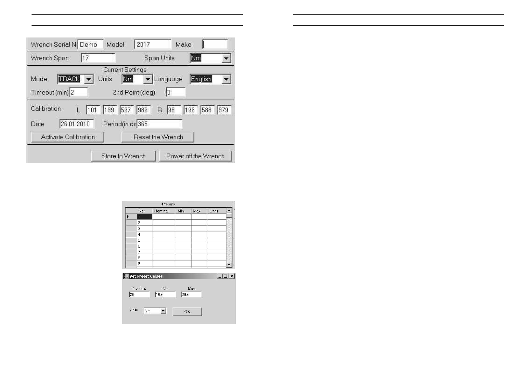
Wrench Span and units - Change these and tool must be re-calibrated
5.4 Set a Preset using the PCFE
1. Ensure the wrench is
connected to the PCFE
software
2. Select the preset number or
location from 1 to 99 you wish
to set
3. When the pop up window
appears, fill in required fields
and press OK
4. Select Store to wrench and the
data is written to the wrench
5. Select Preset option on the
wrench and select the preset
required
1.3 Care Guidelines
These Instruments should be handled with care. Do not subject to Torque Loads in
excess of the Model Range. Do not use Tool to loosen fasteners tightened beyond
Max Tool Capacity - Never apply extensions to Tool without contacting your
supplier.
Do not Drop or Subject to Impact Blows - Provide adequate storage to Protect from
Damage - Adhere to Safety Instructions
Changing the Battery on Wrenches - Note: Battery life should last 160hrs+
1. Unscrew the metal End Cap on the handle of the wrench.
2. Remove the four AAA cell batteries and replace with new.
3. Screw back the metal End cap.
4. Check to ensure the date and time are correct
Ratchet head guidelines
1. Store in a dry location
2. Oil Frequently to prevent Ratchet head seizing
3. Do not exceed specified torques
4. Do not use external forces on Ratchet ( i.e. Hammer)
Max Torque for 1/4" Ratchet = 30 Nm
Max Torque for 3/8" Ratchet = 135 Nm
Max Torque for 1/2" Ratchet = 340 Nm
Electromatic Equipment Co., Inc.
-18-
Electromatic Equipment Co., Inc.
-3-
Page 4
2.0 PCFE DESCRIPTION
Select port: select communication port you wish to use to communicate
with the wrench
Change password: Type current password. Type new password. Confirm new
password
Current mode: Select mode you wish wrench to operate in. Selection will
take effect after data is stored using ‘store to wrench
button’
Current units: Select the units you wish wrench to operate in. Selection
will take effect after data is stored using ‘store to wrench
button’
Current language: Select the language you wish wrench to operate in.
Selection will take effect after data is stored using ‘store to
wrench button’
Wrench span: The span of measurement of the wrench for example Span
100Nm would have a range of 2-100Nm.
Period of calibration: Set number of days to next calibration or it can be set by
Calibrated on: Date of last calibration.
number of measurements.
Activate calibration: Activates the calibration option in the wrench menu. You
must begin calibration before the wrench powers down.
Default calibration: Allows wrench reset. All data/settings stored in the wrench
will be cleared and default calibration values for the
Power off wrench: Allows soft power down of the wrench.
wrench’s specific calibration span will be programmed.
Store to wrench: Store all current pc front settings to wrench. Wrench will
automatically power down after store.
Load from file: Loads a previously created file containing preset data, into
Save to file: Saves PCFE displayed preset data to file.
Clear all presets: Clears presets from the PCFE presets window.
the PCFE front preset window (top left).
Set a preset: Click on any preset location number in the PCFE presets
window. Set the required nominal, min, max Tolerance and
units. Store settings to the wrench.
Continuous upload: Allows real time communication of measurements to the
PCFE. Wrench must be connected to the PC.
Electromatic Equipment Co., Inc.
-4-
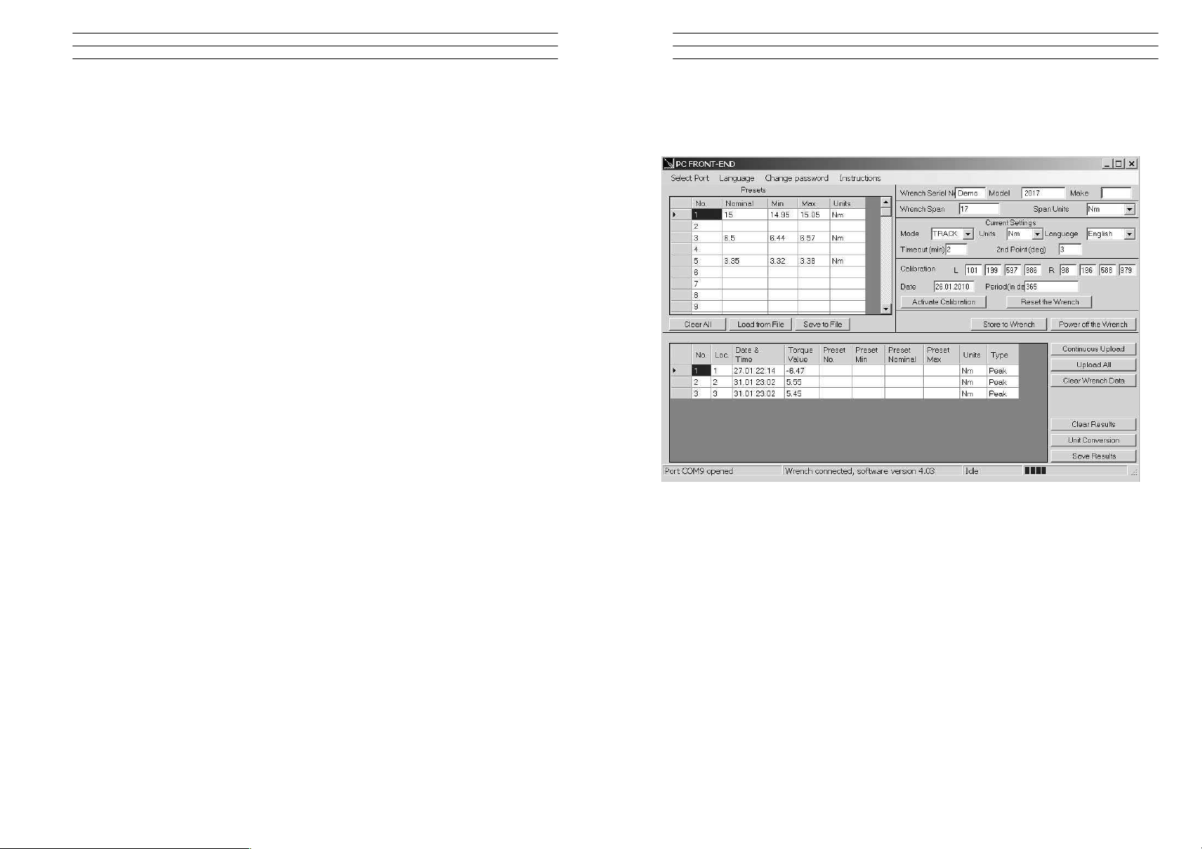
5.3 PCFE Window
The Top half of the PCFE displays Wrench Configuration data, the Bottom section
allows the user to manage the stored wrench data.
The right upper half of the PCFE windows, displays data such as Wrench serial
Number, Make, Model, Wrench Span and Units of measurement. The date of
calibration and the period of calibration are also shown in this section.
The left upper section displays the Presets stored in the wrench - the user can
choose to use the PCFE to set the preset's or it can be done manually on the
wrench.
The bottom half of the PCFE window displays any stored measurements on the
wrench It displays wrench location number, date and time of reading, Torque
readings, Preset data, units of measurement and the mode that was used to take
the torque measurement.
Electromatic Equipment Co., Inc.
-17-
Page 5

5.0 PCFE INSTRUCTIONS
5.1 Changing the Password
Only available in the "Master Version" of the PC Front End.
1. Click " Change Password" on the PCFE
2. Enter the "Current Password" ( "master" is the default password)
3. Enter New Password in "New Password Box"
4. Enter New Password in "Confirm Password Box" to Confirm.
The Default Password for access
to Master PCF E is "master ".
The Default Password for the
Distributor PCFE is "distr"
Passwords must be changed by
Distributor / Calibration Vendor
prior to End User Usage.
5.2 Language
The PCFE languages available
include; English, French, German,
Italian, Polish, Portuguese, Spanish,
Russian and Chinese
Upload all: Displays all stored wrench measurement data in the the
Clear: Clears the wrench measurement data displayed on the PC.
PCFE data window (lower left)
Clear wrench data: Clears the wrench measurement data displayed on the
PCFE and in the wrench.
Unit conversion: Allows user to change the units of the displayed
measurement data on the PCFE.
Sort by preset: Sort the displayed measurement data and group according
to ascending preset numbers.
Save as an excel file: Save the current displayed measurement data as an excel
file.
The PCFE measurement data window displays stored wrench measurements
showing wrench memory location, date and time, torque value.
Electromatic Equipment Co., Inc.
-16-
Electromatic Equipment Co., Inc.
-5-
Page 6

3.0 OLED DISPLAY
Reading starts at 2% of Maximum with an Accuracy of 1% beginning at 10% of
Maximum (Threshold to Maximum Span).
Press MENU to select the required Menu option OK and to select:
3.1 Language Mode - Keypad Function
1. Press MENU to Scroll to the Language Menu
2. Press OK to enter Lang Menu
3. Press UP or DOWN to Scroll to Language Required
4. Press OK to Confirm operation in this Language.
The Languages of Operation available to the User
are; English, Chinese, French, German, Italian,
Polish, Portuguese, Russian, Spanish
3.2 Unit Mode - Keypad Function
1. Press MENU to Scroll to Units Menu
2. Press OK to enter Units Menu
3. Press UP or DOWN to Scroll to Units Required
4. Press OK to confirm selected units
The following Units of Measure are available;
kgf.cm - kgf.m - cN.m - N.m - ozf.in - lbf.in - lbft.ft
Binary Data Transfer
For this the BIN menu item must be selected on the wrench. This is similar to the
ASCII data transfer. Returned data format is as follows:
Day (1 Byte) Month (1 Byte) Hour (1 Byte) Minutes (1 Byte) Torque value (3 Bytes)
Torque units indicator (1 Byte, see below) Pre-set index (1 Byte) Pre-set high setting
(3 Bytes)
Pre-set
low setting (3 Bytes) Pre-set nominal setting (3 Bytes) Pre-set units indicator (1
Byte)
There are no separators between the different data items.
The torque and pre-set units are expressed as follows:
Units Units indicator byte contents
LBFT 0
LBIN 1
OZIN 2
NM 3
CNM 4
MKG 5
CMKG 6
Individual measurement mode
This is initiated by transmission of the single byte hex value 6D Block transfer mode
This is initiated by the transmission of the single byte binary value 62 The clear to
send character is single byte binary 72 When all data is transferred the wrench
responds with a single byte binary 65
Electromatic Equipment Co., Inc.
-6-
Electromatic Equipment Co., Inc.
-15-
Page 7

4.5 Wrench Data Transfer Protocol
General
The data transfer protocol allows measurement data along with the associated
date/time stamps and pre-set limits to be transferred from the wrench to other
equipment such as a PC or a PLC controller.
Data can be transferred in either ASCII or binary formats and data transfer can be
on a measurement by measurement basis or as a complete upload of internal
memory.
Data Link Settings
All data is transferred in 8 bit bytes, single start bit, single stop bit, no parity at a
speed of 9600 bits per second.
ASCII data transfer
For this the ASCI menu item must be selected on the wrench.
Individual measurement transfer
This is initiated by transmitting the ASCII character ‘m’ to the wrench. Once the
wrench receives this it remains in individual measurement transfer mode until it
powers down. Data can be transferred from the wrench whenever the ‘Store?’
prompt is ticked in peak or preset mode.
The data format is as follows:
Day, Month, Hour, Minutes, Torque value, Torque units, Preset index, Preset high
setting, Preset low setting, Preset nominal value, Preset units
Each item is separated by a comma and can be used to feed a CSV spreadsheet
file. In peak mode the pre-set values (high, low and nominal) are set at 0.
Block transfer
This is initiated by transmitting the ASCII character ‘b’ to the wrench. Once the
wrench receives this it transfers the entire data memory contents to the external
device. The data is separated into individual measurements containing the date/time
stamp, measured value and pre-set data, as described in the data format above.
The first measurement data are transmitted immediately after reception of the ‘b’
character. After each measurement data are transmitted the wrench waits for a
‘ready to receive’ signal in the form of the ASCII character ‘r’. Once this is received
the next measurement data are transmitted. When all memory data has been
transmitted the wrench will respond with the ASCII character ‘e’.
3.3 Date Mode - Keypad Function:
1. Press MENU to Scroll to the Date Menu
2. Press OK to enter Date Menu
3. Press UP or DOWN to to Set the min/Hour
4. Press OK to Confirm
To Set Day / Month / Year - repeat Steps 3 & 4
3.4 Trac Mode
As Torque is applied to the Wrench it will actively
display the applied Torque reading to the Max
Span of the Device. On removal of the Torque
Load the display will return to Zero.
1. Press MENU to Scroll to Trac Mode
2. Press OK to operate in Trac Mode
3.5 Peak Mode
In Peak Mode the Torque Reading will remain
Displayed when the Torque Load is removed. The
User has the option to store the reading in Memory.
If storage of the reading is not required the User
may continue to the next measuring task.
1. Press MENU to Scroll to Peak Mode
2. Press OK to select Peak Mode and then apply
Torque
3. Press OK to store the Peak Value Recorded if
required.
If Storage is not required then apply New Torque
3.6 Set Mode
This mode allows the user to set the limits for
Torque, Just Move and Torque and angle.
The operator can choose to set Torque values
by % or by tolerances. The OLED display will
be Green approaching Preset tolerances and
will change to Red if exceeded.
Electromatic Equipment Co., Inc.
-14-
Electromatic Equipment Co., Inc.
-7-
Page 8

3.7 Set Mode - Torque & Angle
1. Press MENU to Scroll to Set Mode, Press
OK and you'll see option to "Set Torque" or
"Set Torque and Angle" or "Just Move Preset"
2. If you are setting a Torque only preset see
page 8 of these instructions.
3. Press UP or DOWN To select select "set
Torque and Angle" and press OK when highlighted green
4. Press To select the Preset number you want
to use and press OK
5. Press UP or DOWN to select your preset
Torque and press OK
6. Press UP or DOWN To set the Angle preset
Value and press OK
7. Press MENU to go to Preset menu
8. Press UP or DOWN to select the Preset
location
9. Press OK to select your required Preset and
take measurements
10. Press OK to store the readings you are taking
3.8 Set Mode – Torque
1. Press MENU to Scroll to Set Mode
2. Press OK to select and UP or DOWN to
select type of Preset, Set Torque or Torque
and Angle
3. Press OK to select Torque
4. Press UP or DOWN to select Set by % or Set
by Tolerance
5. Press UP or DOWN to Scroll to required
Preset No. (1 to 99)
6. Press OK to Confirm Preset No. selected
7. Press UP or DOWN to Set Nominal Value and press OK
8. Press UP or DOWN to Set Your Low Value and press OK
9. Press UP or DOWN to set your High Value and press OK
10. Use MENU to select Preset from the menu to use this set-up
To set a Preset as a +/- % Deviation of the Nominal Value, Please select "Set
Torque" and then select "by %"
4.2 Torque and Angle Calibration
1. Immediately after the regular Calibration the user is prompted to "wait" - the
Gyroscope is doing a self test at this stage
2. The user is then prompted to rotate the wrench by 180 degrees and press OK to
complete the calibration
4.3 Communication to PCFE
To Establish Communication with the Wrench - Using RS232 Cable
1. Place the RS232 Cable in the COM 1 PC Port. Note: Available PC Port
configurations may vary. It is important that communications are attempted with
the correct PC Port. The PC Link has been designed for connection with the
standard 9-Way D-Type PC Port.
2. Place the other end of the cable into the wrench Jack Plug socket.
3. Switch on the wrench by pressing any button on the wrench. Select the correct
Com port on the PCFE. Now the PCFE will automatically connect to the wrench
and the screen will fill with data from the wrench
4. When you are finished communicating with the wrench, remove the cable from
the wrench.
4.4 Communication using USB Cable
1. The installation checks the PC for the .net framework and installs it from the web
if required.
2. Install the USB driver - It can be found at C:/program files/PCFE/Front-end/USB
drivers. After PCFE installation, the PC wizard will ask you to install this driver
for the new hardware
3. The PCFE Icon is on the desktop, the password is "master" - you can re-size the
screen and it will remember this setting on next time of opening.
The PCFE communication operates as follows:
Firstly connect USB cable to PC and to the Wrench or screwdriver and power up the
tool. Open the PCFE with "master" as the password, This password can be changed
see page 16 Select Com port.
there will be two options:
1. Com Port 1 - this will allow you to connect the older type tools using the RS232
cable.
2. Com port x - it 's a virtual port and will vary from PC to PC.
Note: After you configure or view data on the Wrench and disconnect from PCFE,
select Com port 1 afterwards to close the virtual port.
Electromatic Equipment Co., Inc.
-8-
Electromatic Equipment Co., Inc.
-13-
Page 9

4.0 WRENCH CALIBRATION
Calibration is achieved using four Measuring Points, namely 10%, 20% , 60% and
100% of Maximum Span of the Wrench. In Calibration Mode the Wrench will
automatically display these Measuring Point Values initially for the Right Hand and
then for the Left Hand. All Products should be 1% accurate.
Calibration Mode is only accessible through the Master & Distributor Versions of the
PC Front End. The End User cannot access the Calibration Mode. Please ensure
that certified calibration systems such as a Norbar ISO 1000 Transducer system are
used when calibrating the Torque wrenches, These devices are themselves
accurate to 0.25%
Note: De-stressing wrench implies that the wrench is torqued to it's maximum span
4.1 Calibrate Mode
Note: Ensure date & time on wrench are correct
1. Connect wrench to PCFE software and Click the Activate Calibrate Button
2. Press MENU on the Wrench to scroll to Calibrate Mode. Place Wrench onto
Calibration Unit. De-stress on the CW (Clockwise) direction
3. Press OK to activate Calibrate Mode (The Wrench OLED will now display a
reading of 10% of the Maximum Span of the Wrench)
4. Apply Torque to the Wrench until the Reading on the Calibration Rig is equal to
the Reading on the Wrench (10% of Maximum Span)
5. Press OK to confirm that the First Point of Calibration is now set
6. Now Measurement Point No.2 (20% of Maximum Span) will appear on the
Wrench OLED Display. Therefore repeat Steps No.4 & No. 5
7. Now Measurement Point No.3 (60% of Maximum Span) will appear on the
Wrench OLED Display. Therefore repeat Steps No.4 & No. 5
8. Now Measurement Point No.4 (100% of Maximum Span) will appear on the
Wrench OLED Display. Therefore repeat Steps No.4 & No. 5
9. Repeat Step No's 1 to 8 for the Left Hand calibration
10. Once calibration is complete select Trac mode on wrench. On the Left hand side
check wrench accuracy at 20%, 60% and 100% according IS06789-2003. Now
De-stress on Right hand side and repeat step 10
3.9 Set Mode - Just Move Preset
This allows the user to change the default Just Move Angle to any Angle between 1
and 10 degrees - The operator Can do this using the PCFE or using the Wrench.
1. Press MENU to Scroll to Set Mode
2. Press OK to select and UP or DOWN to select Just Move Preset
3. Press OK to select Just Move once it's high-lighted green
4. Use UP or DOWN keys the to select between 1 and 10 degrees and press OK
5. Use UP or DOWN to select Just Move and the default angle will be changed
3.10 Just Move
This function will display the Torque that was applied after 3 degrees of movement,
It will also show the final Torque and angle that were applied by the user. The
screen will change to Red once the Just move Angle threshold is passed and the
Buzzer will sound. The user can set the Just move degree in the "Set" menu option
or using the PCFE software. The Final torque and final Angle that was achieved will
also be displayed as shown. The default Just Move Angle is 3 degrees.
1. Press MENU to Scroll to Just Move Mode
2. Press OK to select Just Mode and then apply Torque and Angle
3. Press OK to store the 3 degree Torque Value and Final Torque and Angle value
If Storage is not required then apply New Torque and Angle measurement
Just Move Default to 3 degrees Just Move Measurement Just move result
3.11 Just Angle
This function will display the Peak Torque and Peak angle that were applied during
the Torque operation. The user can store the result at the end of each
measurement.
1. Press MENU to scroll to Just Angle and OK to select
2. Take a Torque and Angle reading
3. Press OK to store the result or apply another torque to continue
Electromatic Equipment Co., Inc.
-12-
Electromatic Equipment Co., Inc.
-9-
Page 10

3.12 Preset Mode
This Mode allows the User to take measurements based on the Nominal, TMax &
TMin of Torque Settings with the relevant Warning Signals activated.
Min Value: The Green LED on keypad will Flash & the Buzzer will Sound
intermittently. The OLED display will change to green.
Nom Value: The Green LED on keypad will switch on & the Buzzer will sound
continuously, The OLED display will be Green.
Max Value: The Red LED will Flash continuously and the Buzzer will sound
continuously and the OLED will change to Red.
3.13 Preset Mode - Keypad Function
1. Press MENU to Scroll to Preset Mode
2. Press OK to Enter Preset Mode
3. Press UP or DOWN to select your preferred Pre-set No. (1
TO 99)
4. Press OK to operate within this preset parameter
5. Press OK to store the applied Torque (Torque and Angle)
if required.
3.14 Recall Mode
This mode allows the User to view the Stored Torque & angle Data. Only Locations
containing data will be displayed. Note that as data is stored the locations are
populated sequentially from 01 to 2094
3.15 Recall Mode - Keypad Function
1. Press MENU to Scroll to Recall Mode
2. Press OK to enter and view Memory Locations,
Results and Functions
3. Press UP or DOWN to scroll through locations that
contain data.
3.16 Upload Mode
This Mode allows the User to Upload Stored Torque Data from an individual or
range of locations. In Upload Mode the Wrench must be connected to a PC running
the PC FRONT-END Software (PCFE) via the USB Port on the Wrench and PC.
Note: The PCFE must have USB drivers installed for communication
1. Press MENU to scroll to Upload Mode
2. Press OK to enter Upload Mode
3. Press OK to select "From" and UP or DOWN to select
the first location to upload
4. Press OK to confirm "From" location
5. Press OK to select "To" location and UP or DOWN for
end location to be uploaded
6. Press OK to confirm, you are asked if your Sure press OK to confirm
3.17 Clear Mode
This Mode allows the User to Clear the Stored Torque Data from an individual or
range of locations.
Note: Before clearing the selected range and as a safety precaution, the user will be
asked are they sure they wish to clear selected data. This can be done by pressing
the confirm button.
1. Press MENU to Scroll to Clear Mode
2. Press OK to enter Clear Mode
3. Press UP or DOWN to select "From" range to be cleared and press
4. Press UP or DOWN to confirm "To" range to be cleared
5. Press OK to confirm and you will be asked if your "Sure?"
6. Press OK to confirm and that Range of data is cleared from the wrench memory
Electromatic Equipment Co., Inc.
-10-
Electromatic Equipment Co., Inc.
-11-
Page 11

DIGITAL TORQUE WRENCH
ETW
OPERATING INSTRUCTIONS
 Loading...