

Page 1

NOTES
TABLE OF CONTENTS
01.0 Introduction .......................................................................................................... 0 2
02.0 Overview ............................................................................................................ 0 3
2.1 Operating Elements
2.2 Installing And Replacing The Battery
2.3 Turning The Power On and Off
0 2.4 Reversing The Display
0 2.5 Selecting The Unit Of Measure
0 2.6 Zero Adjustment of the Measurng Position
03.0 Removing and Re-Mounting The Filament Guide ............................................... .w. 6
04.0 Taking A Measurement ......................................................................................... 07
4.1 Inserting The Process Material
4.2 Measuring
4.3 Removing The Process Material
05.0 Damping Mode ...................................................................................................... 08
5.1 Switching On The Damping Mode
5.2 Switching Off The Damping Mode
5.3 Changing the Damping Factor
06.0 Memory Modes ...................................................................................................... 09
07.0 Recalling Tension Values Stored In Memory ........................................................ 14
7.1 Recalling Tension Values In Standard Mode
7.2 Recalling Tension Values In Continuous Mode
7.3 Recalling Tension Values In Limit Mode
7.4 Recalling Tension Values in Fast Mode
7.5 Clearing the Memory
7.6 Memory HOLD function
7.7 Error Messages
08.0 Static Verication of Measuring Accuracy ............................................................ 19
09.0 Calibration ............................................................................................................. 20
9.1 Dynamic Calibration
9.2 Static Calibration
9.3 Error Messages
9.4 Restoring Factory Defaults
10.0 WINDOWS Terminal Program .............................................................................. 23
11.0 Specications ....................................................................................................... 24
12.0 Appendix B - Replacing the Rollers / Ceramic Pins ............................................ 25
TensionInspect 3 Software ................................................................................................ 27
Warranty .......................................................................................................................... 35
– 36 –
–1 –
Page 2

1.0 INTRODUCTION
WARRANTY
Three long, closely-spaced slender shafts with precision guide rollers or pins attheir
ends combine with the latest in microprocessor technology to make this instrument top
choice for all limited-access, tension measuring applications.
Store up to 4000 displayed tension values in memory and statistics (Last, AVG, MIN,
MAX, MIN-PEAK, MAX-PEAK), which can be transmitted using the serial output
port.
Choice of miniature, high speed rollers for lament speeds up to 2000 m/min or nonrotating, ceramic pins for speeds to 6000 m/min. Uses part number ETMX or ETMPX
to designate model with ceramic pins.
Available Models - The standard series is also available with the following
modications. (Special calibration using customer supplied material.)
Model
Tension
Ranges
cN
*Measuring
Head Width
mm
Calibration
with running filament
ETMX-100 0.5 - 100.0 24 PA: 0.20 mm Ø
ETMX-200 1 - 200 24 PA: 0.20 mm Ø
ETMX-500 1 - 500 24 PA: 0.20 mm Ø
ETMPX-100 0.5 - 100.0 24 PA: 0.20 mm Ø
ETMPX-200 1 - 200 24 PA: 0.20 mm Ø
ETMPX-500
* Outer distance between outside guide rollers / pins
** Suitable for 95% of all applications. PA = Polyamide Monolament.
If the material to be measured differs signicant from the factory calibration material in diameter,
rigidity, shape, etc., we recommend calibration using customer supplied material. For this
purpose a material sample of about 5 m should be supplied. International unit of tensile force:
1 cN = 1.02 g = 0.01 N
ETX: Calibration with approx. 100 m/min
ETPX: Calibration with approx. 60 m/min
1 - 500 24 PA: 0.20 mm Ø
1.1 Unpacking
Unpack the tension meter and inspect it for any shipping damage. Notices of defect must
be led immediately, in writing, at the latest within 10 days of receipt of the goods.
Delivery includes:
1 Tension meter
1 AC-adapter with 3 country-specic
adapters (EU/USA/UK)
1 Open end wrench (4 mm jaw width)
1 Screwdriver (1.5 mm blade width)
1 USB cable
1 ETX-P2: TENSION INSPECT
software (Win 95 or higher) for
viewing and storing the measured
data on a PC.
1 Carrying case
1 Operating Instructions
ELECTROMATIC Equipment Co., Inc. (ELECTROMATIC) warrants to the original
purchaser that this product is of merchantable quality and conrms in kind and quality
with the descriptions and specications thereof. Product failure or malfunction arising
out of any defect in workmanship or material in the product existing at the time of
delivery thereof which manifests itself within one year from the sale of such product,
shall be remedied by repair or replacement of such product, at ELECTROMATIC’s
option, except where unauthorized repair, disassembly, tampering, abuse or
misapplication has taken place, as determined by ELECTROMATIC. All returns
for warranty or non-warranty repairs and/or replacement must be authorized by
ELECTROMATIC, in advance, with all repacking and shipping expenses to the address
below to be borne by the purchaser.
THE FOREGOING WARRANTY IS IN LIEU OF ALL OTHER WARRANTIES,
EXPRESSED OR IMPLIED, INCLUDING BUT NOT LIMITED TO, THE
WARRANTY OF MERCHANTABILITY AND FITNESS FOR ANY PARTICULAR
PURPOSE OR APPLICATION. ELECTROMATIC SHALL NOT BE RESPONSIBLE
NOR LIABLE FOR ANY CONSEQUENTIAL DAMAGE, OF ANY KIND OR
NATURE, RESULTING FROM THE USE OF SUPPLIED EQUIPMENT, WHETHER
SUCH DAMAGE OCCURS OR IS DISCOVERED BEFORE, UPON OR AFTER
REPLACEMENT OR REPAIR, AND WHETHER OR NOT SUCH DAMAGE IS
CAUSED BY MANUFACTURER’S OR SUPPLIER’S NEGLIGENCE WITHIN ONE
YEAR FROM INVOICE DATE.
Some State jurisdictions or States do not allow the exclusion or limitation of incidental
or consequential damages, so the above limitation may not apply to you. The duration
of any implied warranty, including, without limitation, tness for any particular
purpose and merchantability with respect to this product, is limited to the duration of
the foregoing warranty. Some states do not allow limitations on how long an implied
warranty lasts but, not withstanding, this warranty, in the absence of such limitations,
shall extend for one year from the date of invoice.
ELECTROMATIC Equipment Co., Inc.
600 Oakland Ave. Cedarhurst, NY 11516—USA
Tel: 1-800-645-4330/ Tel: 516-295-4300/ Fax: 516-295-4399
Every precaution has been taken in the preparation of this manual. Electromatic
Equipment Co., Inc., assumes no responsibility for errors or omissions. Neither is any
liability assumed for damages resulting from the use of information contained herein.
Any brand or product names mentioned herein are used for identication purposes only,
and are trademarks or registered trademarks of their respective holders.
– 2 –
– 35 –
Page 3

3.9 Print and data transfer
Print:
1. Click the GENERATE button to
open the print review.
2. Click the PRINT THIS PAGE
button to open the printer setup
box.
The print-out includes the
statistical data of the series of
measurements and the current
displayed graph.
Data transfer:
The EXPORT SCREEN TO EXCEL button copies the readings of the desired series
of measuremetns to an Excel le (reading, date, time).With the inxed readings, a graph
can be created in the Excel le.
2.0 OVERVIEW
2.1 Operating Elements
1 ROLLERS or ceramic pins
2 DISPLAY
3 POWER / ZERO key
4 MEM key
5 RECALL / HOLD key
6 DAMP key
7 LEVER
8 FILAMENT GUIDE
9 INTERFACE
3.10 Save the readings
Save:
With the button SAVE stored values (statistics and series of measurements) of the
connected tension meter can be downloaded and stored as CSV le. Te individual series
of measurement can be selected.
Readings which have be downladed and be stored as CSV le cannot be related to
Tension Inspect 3
– 34 –
2.2 Battery Management & Charging
The tension meter has a built-in rechargeable LiPo battery, which has been charged at
the factory. The tension meter can only be switched on if the battery has enough charge.
If the instrument does not power up or if the battery level indicator shows only one bar
after power-up the battery needs to be recharged.
NOTE: To ensure maximum battery life, avoid discharging it completely or charging it
frequently for short periods. The battery should not be stored for a prolonged time when
empty. After a maximum storage period of one year, the battery has to be recharged.
Charging the Battery
NOTE: The battery must be charged at a temperature between +5 °C and
+45 °C. Before connecting the AC adapter, verify that the supply voltage is
correct (100 V – 240 V). Electromatic provides no warranty or liability for
damage resulting from the use of AC adapters from other manufacturers.
To charge the battery, connect the cable of the AC adapter to the low USB output. The
battery can also be charged by connecting the USB cable to a PC. When the battery is
fully charged, the battery level indicator will show 3 bars . The charging time is
approx. 3 ½ hours. Battery overcharging is not possible.
– 3 –
Page 4
2.3 Turning the Power On and Off
Power On: Press the POWER key until the DISPLAY momentarily shows the tension
range and the software version, e.g. E 1.0, followed by random values or “0.”
Auto Power Off: The tension meter switches off automatically after
3 minutes of non-use.
Manual Switch-Off: Press the POWER key for 5 seconds.
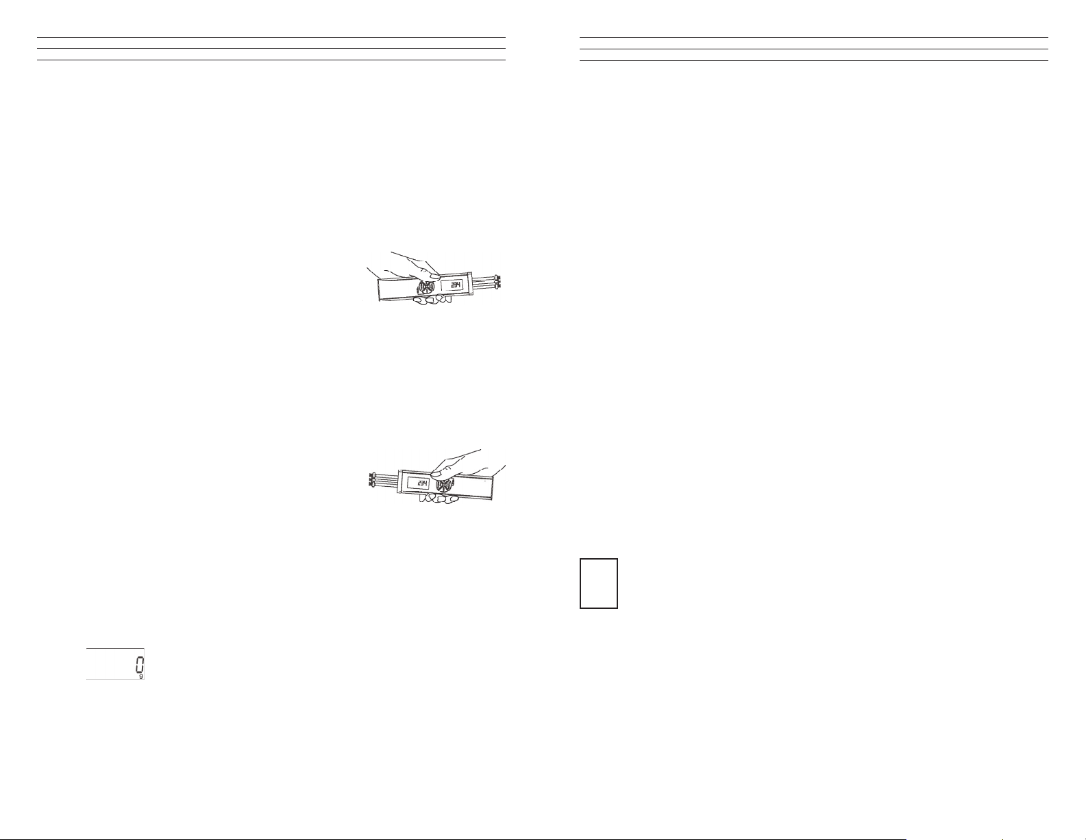
2.4 Reversing the Display
When you shift the tension meter from the right to the left
hand, you can rotate the readings on the DISPLAY by 180°.
Measuring with the left hand:
If you would like to use the left hand for measuring, you should reverse the readings on
the DISPLAY to make them easier to read.
1. Tension meter switched off as described above.
2. Press and hold the DAMP and POWER keys until the DISPLAY shows the
readings the other way around.
Measuring with the right hand:
1. Tension meter switched off as described above.
2. Press and hold the DAMP and POWER keys until
the DISPLAY shows the readings in the default
(right-handed) orientation.
3.7 Download the tension data from the ETX (ETPX) to the PC
Requirements:
- Tension meter connected to the PC
- Tension meter switched on.
To download the tension data:
1. Click the READ button. The tension data stored in the tension meter are
read into the PC.
Tension value display:
TENSION Graph of the displaye series of measuremnts
STATISTICS Statistical data of the displayed series of measuremnts
3.8 Graph adjustments
SCALE Manual scaling of the Y-axis which starts at „zero“. This feature can
be activated by pressing RESET.
AUTOSCALE Automatic scaling of the Y-axis depending to the displayed readings
of the diagram.
RESET Activates the scaling, which is set in the pop-up SCALE.
2.5 Selecting the Unit of Measure
You can set the ETMX to the cN or g unit of measure, depending on the required tension
range. The default setting is cN.
1. Tension meter switched off as described above.
To select the unit of measure:
2. Press and hold the RECALL and POWER keys until the new unit of measure
is indicated on the DISPLAY.
– 4 –
ZOOM A big number of zoom features can be selected to enlarge a selected
frame of the diagram.
The button ZOOM and RESET work only if AUTOSCALE is not activated.
i
– 33 –
Page 5
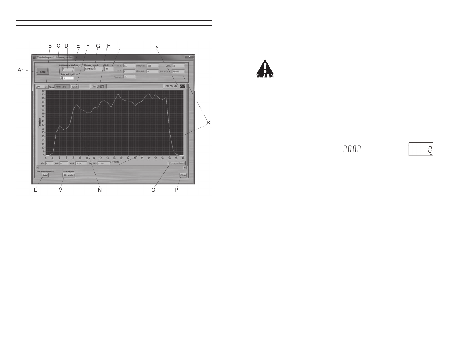
A Button READ Section 3.7
B Choice box SCALE Section 3.8
C Button AUTOSCALE Section 3.8
D Display POSITON IN MEMORY Number of saved series of measurement
E Choice box SELECTED POSITION Selected series of measurement
F Button RESET Section 3.8
G Display MEMORY MODE Used memory mode during the
measuring
H Button ZOOM Section 3.8
I Display UNIT measuring unit of the readings
J Display DEVICE TYPE Display the connected unit
K Display STATISTICS Statistical data of the displayed series of
measurement
L Button SAVE Section 3.10
M Button GENERATE Section 3.9
N Display TENSION Readings as graph
O Button EXPORT TO EXCEL Section 3.9
P Button CLOSE Close MEMORY-REVIEW
2.6 Zero Adjustment of the Measuring Position (Auto Zero)
A Zero Adjustment is automatically carried out for the current measuring postion.
A Zero Adjustment must be carried out whenever the tension meter
does not display “0” in measuring position. The process material must
not yet be inserted!
Procedure:
1. Switch on the tension meter as described in Sec 2.3.
2. Select the unit of measure as described in Sec 2.5.
Do not insert the process material.
3. Hold the tension meter in the desired measuring position. Be careful to hold the
instrument absolutely steady.
4. Press the POWER key.
The DISPLAY momentarily shows and then switches to .
The tension meter is now adjusted for the new material path and is ready to measure.
– 32 –
– 5 –
Page 6
3.0 REMOVING AND REMOUNTING THE FILAMENT GUIDE
The tension meter is supplied with a FILAMENT GUIDE for fast and easy material
acquisition. For application in hard-to-reach areas with limited access space, you can
remove the FILAMENT GUIDE.
GUIDE ROLLERS (2x)
FILAMENT GUIDE
MEASURING ROLLER
Removal Procedure
1 Loosen the SETSCREWS (2x) with the supplied screwdriver (1.5 mm blade).
2. Unscrew and remove the GUIDE ROLLERS (2x) with the supplied open end
wrench (jaw width 4 mm).
3. Slip the FILAMENT GUIDE off the ROLLER SHAFTS.
4. Screw the GUIDE ROLLERS (2x) back onto the ROLLER SHAFTS and carefully
tighten using the supplied open end wrench (jaw width 4 mm) until hand-tight.
Remounting Procedure
1. Unscrew and remove the GUIDE
ROLLERS (2x) with the supplied
open end wrench jaw width 4 mm).
2. Slip the lament guide on to the
ROLLER SHAFTS.
3. Screw the GUIDE ROLLERS (2x)
back on to the ROLLER SHAFTS
and carefully tighten them using the supplied open end wrench (jaw width 4 mm)
until hand-tight.
4. Push the FILAMENT GUIDE forward far nough to ensure that the rollers do not rub
against the FILAMENT GUIDE and that the process material can slide unhindered
from the FILAMENT GUIDE into the roller grooves (g. CENTER LINE).
5. Carefully tighten the SETSCREWS (2x) with the supplied screwdriver
(blade width 1.5 mm) until hand-tight.
CENTER LINE
3.4 Printing and Data Transfer
Print:
1. Click the GENERATE button
to open the print preview.
2. Click the PRINT THIS PAGE
button to open the printer setup
box.
The print-out includes the
statistical data of the series of
measurements, the current
displayed graph and the
statistical values of the graph.
Data transfer:
1. The EXPORT SCREEN TO EXCEL button copies the readings, which are
displayed at the graph to an excel le (reading, date, time).With the inxed readings,
a graph can be created in the Excel le.
3.5 Save and load the readings
Save:
1. The statistical data, as well as the single readings of a measuring can be saved after
the measuring ends as CSV le, by clicking the the SAVE button.
Load:
1. Click the LOAD button and open the required le. The statistical data of the saved
measuring, the graph and the statistical data of the graph are displayed in
Tension Inspect 3
It is possible to add readings to an existing le. In this case open the le and start a
new series of measurements. The new readings will be added in the diagram. After
this store the complete CSV le again. If any readings are in the internal memory
i
before opening the existing le, the internal memory will be overwritten.
3.6 The READ button (Available only for ETX and ETPX)
With the TENSION INSPECT 3 program you can download all the tension data stored
in the memory of the connected tension meter.
Start the DOWNLOAD
1. Click the READ button.
The MEMORY-REVIEW window opens.
– 6 –
–31 –
Page 7

3.2 Starting and Stopping the Tension Value Display
NOTE: Before beginning, click the CLEAR GRAPH button to clear all readings shown
in the TENSION display, if any.
Start:
1. Click the red START STOP button to activate the display of tension values.The
button color changes to red (function enabled).
Tension value display:
TENSION display Current graph
TENSION display Current digital value
STATISTICS display Continuously updated statistics
STATISTICS DIAGRAM display Continuously updated statistics of readings shown
in the graph
Stop:
1. Click the now red START STOP button.
The display of the tension values stops. The button color changes back to green
(function disabled).
3.3 Graph adjustments
SCALE The maximal tension value of the diagram can be adjusted
(Y-axis, starts at „zero).
AUTO Automatic scaling of the Y-axis depending on the
measured tension values.
RESET Change of scaling from mode AUTO to SCALE
READINGS ON SCREEN To set the number of readings to be shown in the diagram
(Timescale) (X-axis). The scroll bar turns to red, if more
readings are selected for the diagram than measured.
TIMESHIFTBUFFER Indicates in % the ll level of the memory. The maximal
numbers of readings will be set in the SETUP.
TIMESHIFT To select the timeframe of a series of measurements, that
should be displayed in the diagram. If the setup Value of
READINGS ON SCREEN bigger or equal to the
recorded readings, the scroll bar can not be moved.
4.0 TAKING A MEASUREMENT
NOTE: Before taking a measurement, be sure that the correct unit of measurement (
g or cN) has been selected and a zero adjustment has been performed.
4.1 Inserting the process material
1. Press the LEVER to tilt the outer GUIDE ROLLERS sidewards.
2. Thread the PROCESS
MATERIAL through the
MEASURING and
GUIDE ROLLERS
(lament guide).
3. Slowly release pressure on
the LEVER until the GUIDE
ROLLERS returnto their
original position.
NOTE: It is important to
assure that the PROCESS
MATERIAL runs smoothly
between the MEASURING
and GUIDE ROLLERS.
4.2 Measuring the process
material
The DISPLAY now shows the
measured tension values. Error
messages which might be displayed
are described in Sec.7.7.
4.3 Removing the process material
1. Press the LEVER and remove the PROCESS MATERIAL.
2. Slowly release pressure on the LEVER until the GUIDE ROLLERS
return to their original position.
– 30 –
– 7 –
Page 8

5.0 DAMPING MODE
The tension meter is equipped with an electronic damping that ensures steady readings
when tension ucutates. This is achieved by averaging the measured values at the preset
update rate.
5.1 Switching On the Damping Mode
NOTE: Before switching on the damping mode, it is recommended that you measure
the rst values without damping enabled.
1. Insert process material as described in Sec. 4.1.
2. Press and hold the DAMP key. The DISPLAY shows the currently set damping
factor.
3. Release the DAMP key. The DISPLAY shows DAMP below
the currently measured value.
5.2 Switching Off the Damping Mode
1. Press and release the DAMP key. If the DISPLAY shows only
the currently measured value, damping is off.
5.3 Changing the Damping Factor
The tension meter is factory preset to a damping factor of 12. The tension values are
thereby averaged for the display in the following way:
12 old values + 4 new values
16
The damping factor can be modied in 15 steps from 01 = low damping:
1 old value + 15 new values
16
to 15 = high damping:
15 old values + 1 new value
16
1. Switch on the tension meter
2. Press and hold the DAMP key. The DISPLAY shows the set damping factor.
3. You can now increase the damping factor by pressing the MEM key and
decrease it by pressing the RECALL key.
4. Release the DAMP key to return to the measuring mode.
NOTE: The damping factor stays stored in memory even after the gauge is turned off.
22.1
D cN
22.1
D cN
15 Button LOAD Section 3.4
16 Display STATISTICS DIAGRAM Display the statistical values, shown
currently at the graph.
17 Button CLEAR ALL DATA Clear all measuring values
18 Display READINGS ON SCREEN To adjust the number of measuring
values, shown at the display
19 Display TENSION Readings as graph
20 Button GENERATE Section 3.3
21 Button EXPORT SCREEN Section 3.3
22 Button EXIT Close Tension Inspect 3
3.1 Basic Settings
NOTE: The tension meter to be used must be connected to the PC.
To edit the settings:
1. Click the SETUP button.The setup dialog box opens. You can now either keep
the default values preset in the input boxes or customize them for your specic
requirements.
The gure below shows the factory-preset defaults for a tension meter model ETX-500.
– 8 –
– 29 –
Page 9

3.0 USING TENSION INSPECT
6.0 MEMORY MODE
1. Double click the TENSION INSPECT ICON to start the program.
01 Button SETUP Section 3.1
02 Button START/STOP Section 3.2
03 Choice box SCALE Section 3.3
04 Choice box SAMPLERATE Select the sampling rate
05 Button READ Section 3.5
06 Button AUTO Section 3.3
07 Button RESET Section 3.3
08 Display TENSION Current reading
09 Display UNIT Unit of measure of the readings
10 Display STATISTICS Display of statistical values of the
measurement
11 Display DEVICE TYPE Display the connected unit
12 Display TIMESHIFTBUFFER Section 3.3
13 Button SAVE Section 3.4
14 Display TIMESHIFT Section 3.3
The tension meter features a
data logger with a memory
capacity for up to 4000
readings, with which you
can store different measuring
periods at one or more
machine positions.
The readings are saved 2x per
second, synchronously with
Memory Mode S C L F
Meas. periods,
max.
255 255 255 255
Readings, max. - 4000 4000 4000
Max. no. of rea-
dings per position
- Any 10 Any
Statistics Ye s Yes Yes Yes
Save readings - Ye s Yes Yes
the display update rate, in all memory modes except the “F” mode in which they are
saved 100x per second. All saved readings and statistics can be shown on the display or
transmitted to a PC (e.g. for further processing in Excel). The memory can be allocated
to different measuring periods, depending on the memory mode.
Memory mode “S” STANDARD (default):
The following values of a measuring
period are calculated and saved at a
rate of 2 readings per second:
Average value,
Last value,
Maximum value (MAX),
Minimum value (MIN),
Minimum peak value (MIN PEAK)
Maximum peak value (MAX PEAK)
Individual readings are not saved.
You can save up to 255 measuring
periods.
Memory mode “C” CONTINUOUS:
The following values of a measuring
period are calculated and all readings are
additionally saved at a rate of 2 readings
per second:
Average value,
Last value,
Maximum value (MAX),
Minimum value (MIN),
Minimum peak value (MIN PEAK)
Maximum peak value (MAX PEAK)
You can save up to 4000 readings, split up
into up to 255 measuring periods.
Memory mode “L” LIMIT:
The following values of a measuring
period are calculated and 10 readings are
additionally saved at a rate of 2 readings
per second:
Average value,
Last value,
Maximum value (MAX),
Minimum value (MIN),
Minimum peak value (MIN PEAK)
Maximum peak value (MAX PEAK)
You can save up to 255 measuring
periods with 10 readings each.
Memory mode “F” FAST:
The following values of a measuring
period are calculated and all readings
are additionally saved at a rate of 100
readings per second:
Average value,
Last value,
Maximum value (MAX),
Minimum value (MIN),
Minimum peak value (MIN PEAK)
Maximum peak value (MAX PEAK)
You can save up to 4000 readings, split
up into up to 255 measuring periods.
NOTE: The selected memory mode remains stored in memory even after the instrument
is switched off.
– 28 –
– 9 –
Page 10

6.1 Memory Mode Selection
1. Switch on the tension meter
2. Clear the memory by simultaneously pressing the MEM and RECALL
keys.
3. Press and hold the MEM key.
The DISPLAY shows “S”. This is the Standard Memory Mode
(default). Press the DAMP or RECALL to display the other memory
modes.
Memory mode C (CONTINUOUS):
If the DISPLAY shows C, the LIMIT memory mode is set.
Memory mode L (LIMIT):
If the DISPLAY shows L, the LIMIT memory mode is set.
Memory mode F (FAST):
If the DISPLAY shows F, the FAST memory mode is set.
When you have selected the desired memory mode, you can release
the MEM key. The selected memory mode is now active and the
tension meter switches back to measuring mode.
NOTE: The selected memory mode remains stored in the memory even after the
instrument is switched off.
6.2 Data Logging in Mode S (Standard)
1. Turn on the tension meter.
2. Memory Mode S set as described in Sec. 6.1.
3. Insert process material and begin measuring as described in section 4.0.
To Start Data Logging:
1. Press and hold the MEM key until the DISPLAY shows the
memory mode “S” and the current memory number.
2. Release the MEM key. The tension meter starts logging the
data. While the tension data are stored, the MEM indicator
blinks on the DISPLAY and the currently measured
value is displayed.
S
cN
C
cN
L
cN
F
cN
S 1
cN
Mem cN
TensionInspect 3 Software
1.0 SYSTEM REQUIREMENTS
Computer: PC
Operating System: Windows XP and higher (32 / 64 Bit)
Hard Disk Space: Approx. 200 MB
Installation: CD-ROM drive
2.0 INSTALLING TENSION INSPECT
To be able to restore the original les in case problems occur after the installation,
you should make a backup of your hard disk contents before you start installing.
1. Insert the CD-ROM with the Tension Inspect 3 program into the CD-ROM drive.
2. Start the installation process by double-clicking the application le.
3. Follow the instructions on the screen, to install the software Tension Inspect 3 and
the corresponding USB driver.
4. At the end, click the RESTART NOW button, to nish the installation process.
3
–10 –
– 27 –
Page 11

3. Unscrew and remove the GUIDE ROLLERS (2) using
the supplied open-end wrench (4mm jaw width).
Note: Should any of the three threaded studs be damaged,
replace it with one of the threaded studs supplied with the
new rollers.
4. Carefully screw the new GUIDE ROLLERS onto the
ROLLER SHAFTS.
5. Carefully tighten the new rollers with the open end
wrench until hand tight.
Note: When loosening or tightenng the rollers, steady
the roller bolt with the supplied screwdriver to prevent
the ROLLER SHAFTS from being twisted off.
6. Slide the FILAMENT
GUIDE up the roller
shafts in the direction
of the arrow.
7. Push the FILAMENT GUIDE upwards far
enough to ensure that the rollers do not rub
against the FILAMENT GUIDE and that
the process material can slide unhindered
from the FILAMENT GUIDE into the
roller grooves.
8. Tighten the SETSCREWS (2) with the
supplied screwdriver (1.5mm blade).
ROLLER SHAFTS
Ideal line
To Stop Data Logging:
1. When you want to stop data logging, press the MEM key once again. The statistical
values are calculated from the logged tension data and stored in the following order:
Average value
Last value
Maximum value (MAX)
Minimum value (MIN)
Minimum peak value (MIN PEAK)
Maximum peak value (MAX PEAK)
The MEM indicator is frozen on the display and the current reading is
displayed. The tension meter has changed back to measuring mode.
To Save The Next Measuring Period:
1. Press the MEM key again. The DISPLAY shows the memory
mode “S” and the next memory number.
6.3 Data Logging in Mode C (Continuous)
1. Turn on the tension meter.
2. Memory Mode C set as described inSec. 6.1
3. Insert process material and begin measuring as described in Sec.4.0.
To Start Data Logging:
1. Press and hold the MEM key until the DISPLAY shows the
memory mode “C” and the current memory number.
2. Release the MEM key. The tension meter starts logging the data.
While the tension data are stored, the MEM indicator blinks on the
DISPLAY and the currently measured value is displayed.
To Stop Data Logging:
1. To stop data logging, press the MEM key once again. The statistical values are
calculated and stored in the following order:
Average value
Last value
Maximum value (MAX)
Minimum value (MIN)
Minimum peak value (MIN PEAK)
Maximum peak value (MAX PEAK)
Tension Value - 1 Tension Value - 2 -
Tension Value - N - (up to 4000 tension values in up to 255 measuring periods)
Mem cN
S 2
Mem cN
C 1
Mem cN
3
cN
3
– 26 –
–11 –
Page 12

The MEM Mem indicator is frozen on the DISPLAY and the
GUIDE ROLLERS (2x)
MEASURING ROLLE
current reading is displayed. The tension meter has changed back to
measuring mode.
To Save The Next Measuring Period:
1. Press the MEM key again. The DISPLAY shows the memory
mode “C” and the next memory number.
6.4 Data Logging in Mode L (Limit)
1. Turn on the tension meter.
2. Memory Mode C set as described in Sec. 6.1
3. Insert process material and begin measuring as described in Sec. 4.0.
To Start Data Logging:
1. Press and hold the MEM key until the DISPLAY shows the
memory mode “L” and the current memory number.
2. Release the MEM key. The tension meter starts logging the data.
While the tension data are stored, the MEM indicator blinks on the
DISPLAY and the currently measured value is displayed.
To Stop Data Logging:
1. To stop data logging, press the MEM key once again. The statistical values are
calculated and stored in the following order:
Average value
Last value
Maximum value (MAX)
Minimum value (MIN)
Minimum peak value (MIN PEAK)
Maximum peak value (MAX PEAK)
Tension Value - 1 Tension Value - 2 -
Tension Value - 10 - (up to 10 tension values in up to 255 measuring periods.)
The MEM indicator is frozen on the DISPLAY and the current
reading is displayed. The tension meter has changed back to
measuring mode.
Mem cN
C 2
Mem cN
L 1
cN
Mem cN
Mem cN
3
3
3
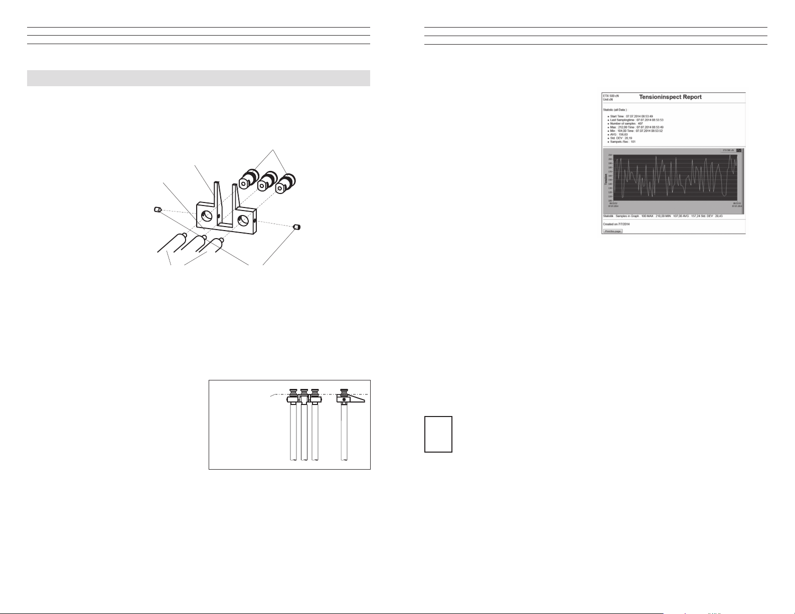
12.0 APPENDIX B - REPLACING THE ROLLERS/CERAMIC PINS
You should regularly inspect the rollers to assure that they are running easily and
smoothly. You can replace the rollers yourself, as necessary, by following the directions
in this section. Please indicate the tension meter model and the serial number (given on
the rear side of the tension meter) in your spare-parts order.
Model ID
Model: 03/04
ETMX-100
# 400 - 88888
Serial number
FILAMENT GUIDE
R
ROLLER SHAFTS (2x)
Procedure
1. Remove the FILAMENT GUIDE by loosening
the SETSCREWS (2) using the
supplied screwdriver (1.5m blade width).
2. Slide the FILAMENT GUIDE down the
ROLLER SHAFTS in the direction of the
arrow.
GRUB SCREWS (2x)
NOTE: Replacing rollers with
ceramic pins or ceramic pins with
rollers can only be performed at
the manufacturer’s facility.
– 12 –
– 25 –
Page 13

11.0 SPECIFICATIONS
Calibration According to SCHMIDT factory procedure
Units of Measure cN / g, user selectable
Accuracy ± 1% FS* ± 1 digit (typical ± 0.5% FS*)
Overrange 10% FS*, without accuracy guarantee
Overload Protection 200% FS*
Measuring Principle: Strain gauge bridge
Meas. Roller Deection 0.5 mm, max
Signal Processing Digital, 16 bit A/D converter
Damping Adjustable electronical (averaging)
Measuring Frequency Approx. 5 kHz internal
Display Update Rate: 2x per second
Display 4-digit LCD, height of digit 11 mm
Memory Average, last value,
maximum, minimum, MAX
Memory Modes: 4 - for up to 4000 readings
Communication frequency 1 to max. 100 readings/sec
Temperature Coefficient Gain: less than ± 0.01% FS*/°C
Digital Output Signal USB (Software Tension Inspect > 50 Measuring
values/sec.)
Temperature Range 10 to 45° C
Air Humidity 85% RH, max.
Auto Power Off Automatical after approx. 3 min. of non-use
Power Supply LiPo accumulator (60 h continouse use, 3 ½ h
charging time) and AC adapter 100 ... 240 V AC
with country-specic adapters (EU/USA/UK)
Housing Material Aluminium prole with plastic outer casing (PVC)
Housing Dimensions 197 mm x 58 mm x 47 mm (L x W x H)
Weight (net /gross): Approx. 340 g / 1250 g
*FS = Full Scale
ETMX Guide Rollers:
V-Groove
Standard 2000
Line Speed
m/min ... max.
Roller
Material
Hardcoated
aluminium
ETMPX Guide Pins:
V-Groove
Standard 6000
Line Speed
m/min ... max.
PEAK
, MIN
PEAK
Roller
Material
Oxide
ceramic
To Save The Next Measuring Period:
1. Press the MEM key again. The DISPLAY shows the memory
mode “S” and the next memory number.
6.5 Data Logging in Mode F (Fast)
1. Turn on the tension meter.
2. Memory Mode C set as described in Sec. 6.1
3. Insert process material and begin measuring as described in Sec.4.0.
To Start Data Logging:
1. Press and hold the MEM key until the DISPLAY shows the
memory mode “F” and the current memory number.
2. Release the MEM key. The tension meter starts logging the data at a rate of 100
readings per second.
While the tension data are stored, the MEM indicator blinks on
the DISPLAY and the currently measured value is displayed.
To Stop Data Logging:
1. To stop data logging, press the MEM key once again. The statistical values are
calculated and stored in the following order:
Average value
Last value
Maximum value (MAX)
Minimum value (MIN)
Minimum peak value (MIN PEAK)
Maximum peak value (MAX PEAK)
Tension Value - 1 Tension Value - 2 -
Tension Value - N - up to 4000 tension values in up to
255 measuring periods.
The MEM indicator is frozen on the DISPLAY and the current
reading is displayed. The tension meter has changed back to
measuring mode.
To Save The Next Measuring Period:
1. Press the MEM key again. The DISPLAY shows the memory
mode “F” and the next memory number.
L 2
cN
F 1
cN
Mem cN
F 2
Mem cN
3
– 24 –
–13 –
Page 14

7.0 RECALLING TENSION VALUES STORED IN MEMORY
Using the Tension Inspect software, you can easily and accurately evaluate the stored
tension values and export them to an Excel spreadsheet.
7.1 Recalling Stored Values in Mode S (Standard)
1. Turn on the tension meter and press the RECALL key, You can exit
recall at any time by pressing the POWER key.
Memory Mode STANDARD
Pos: 1 Pos: 2 Pos: 3 Pos: 4
AVG: 22.0 AVG: 12.0 AVG: 12.0 AVG: 12.0
Last: 23.0 Last: 22.1 Last: 22.1 Last: 22.1
MAX: 24.0 MAX: 22.1 MAX: 22.1 MAX: 22.1
MIN: 21.0 MIN: 5.4 MIN: 5.4 MIN: 5.4
PEAK
PEAK
: 26.0 PEAK
MAX
: 19.0 PEAK
MIN
: 28.1 PEAK
MAX
: 1. 8 PEAK
MIN
: 28.1 PEAK
MAX
: 1. 8 PEAK
MIN
: 28.1
MAX
: 1. 8
MIN
9.3 Restoring Factory Calibration
You can restore the factory calibration at any time with the following procedure:
1. Switch off the tension meter.
2. Press and hold the MEM and POWER keys until the DISPLAY shows E-0 cN .
3. Release rst the POWER key and then the MEM key.
4. Press and hold the DAMP and RECALL keys, then additionally
press and hold MEM until the DISPLAY shows - - - -cN .
The factory calibration is restored.
5. Release the DAMP, RECALL and MEM keys.
6. Press the POWER key. The instrument switches off.
10.0 WINDOWS TERMINAL PROGRAM
E-0
D cN
----
D cN
2. The DISPLAY blinks showing the average value (AVG)
of the rst measuring period (POS: 1) and the
symbol.
3. Press the RECALL key. The DISPLAY blinks, showing
the last value (LAST) of the measuring period.
4. Press the RECALL key. The DISPLAY blinks, showing
the maximum value (MAX) or the measuring period
and the symbol.
5. Press the RECALL key. The DISPLAY blinks, showing
the minimum value (MAX) of the measuring period
and the symbol.
6. Press the RECALL key. The DISPLAY blinks, showing the
maximum peak value (PEAKMAX) of the measuring period
and the symbol.
7. Press the RECALL key. The DISPLAY blinks, showing the
minimum peak value (PEAKMIN ) of the measuring period,
the PEAK indicator and the symbol.
8. Press the RECALL key. The next measuring period (POS: 2) is shown on the
DISPLAY, starting with the average value (AVG).
Peak cN
Peak cN
22
D cN
D cN
24
D cN
D cN
26
23
21
19
The measured values and the memory contents can be transmitted over the USB
interface to a personal computer.
For data transfer to the PC, you will need a USB driver. If no matching driver is installed
on your PC, the Windows Found New Hardware Wizard appears when you connect the
unit to the computer for the rst time. Follow the wizard steps. Specify the location of
the driver on the supplied CD-ROM. You will nd the driver in the “Treiber” folder.
You can connect the computer to the INTERFACE of the ETX by using the EK-0662
special cable which is included in delivery.
Requirements:
A communication program, such as Terminal or HyperTerminal (provided on MS
Windows Version 3.0 or later), must be installed and congured on the computer.
Commands for communication with a PC (polling)
ASCII
Code
s transmission Transmission of the undamped reading.
d Send Transmit current reading to PC once.
r Output Output the memory contents to the PC.
Function Description
–14 –
– 23 –
Page 15

o3rd calibration point:o
1. Repeat steps 1 through 4 from the preceding procedure using a weight which
corresponds to 70% of the tension range
2. Press the RECALL key. As long as the RECALL key is
depressed, the DISPLAY shows a decimal value which is
higher than the second decimal value, e.g., 8000. This decimal
value may vary from instrument to instrument. Write down the
value.
3. Release the RECALL key when the value shown on the
DISPLAY is stable (the reading might uctuate greatly).
The DISPLAY shows E 100.
o4th calibration point:o
1. Repeat steps 1 through 4 from the preceding procedure using a weight which
corresponds to 100% of the tension range
2. Press the RECALL key. As long as the RECALL key is
depressed, the DISPLAY shows a decimal value which is
higher than the third decimal value, e.g., 9500. This decimal
value may vary from instrument to instrument. Write down the
value
3. Release the RECALL key when the value shown on the DISPLAY is stable (the
reading might uctuate greatly).
4. Press and then release the RECALL key. The DISPLAY switches off after
approximately 1 second. The new calibration is stored.
5. Press the POWER key. the instrument switches off.
6. Verify the new calibration, following the directions in Sec. 8.0 If this procedure
shows a deviation, you can recalibrate the tension meter again or restore the factory
calibration as described in Sec. 9.3.
If the verication of the calibration according Sec.8.0 shows a deviation beyond
the allowable tolerance and a reliable operation is no longer allowed, the
instrument has to be returned to Electromatic for factory recalibration.
8000
E 100
9500
7.2 Recalling Stored Values in Mode C (Continuous)
1. Turn on the tension meter and press the RECALL key, You can exit
recall at any time by pressing the POWER key.
Memory Mode CONTINUOUS
Pos: 1 Pos: 2 Pos: 3 Pos: 4
AVG: 22.0 AVG : 12.0 AVG: 12.0 AVG : 12.0
Last: 23.0 Last: 22.1 Last: 22.1 Last: 22.1
MAX: 24.0 MAX: 22.1 MAX: 22.1 MAX: 22.1
MIN: 21.0 MIN: 5.4 MIN: 5.4 MIN: 5.4
PEAK
PEAK
2. The display blinks showing the average value (AVG)
of the rst measuring period (POS: 1) and the
symbol.
3. Press the RECALL key. The DISPLAY blinks, showing
the last value (LAST) of the measuring period.
4. Press the RECALL key. The DISPLAY blinks, showing
the maximum value (MAX) or the measuring period
and the symbol.
5. Press the RECALL key. The DISPLAY blinks, showing
the minimum value (MAX) of the measuring period
and the symbol.
6. Press the RECALL key. The DISPLAY blinks, showing the
maximum peak value (PEAKMAX) of the measuring period
and the symbol.
7. Press the RECALL key. The DISPLAY blinks, showing the
minimum peak value (PEAKMIN ) of the measuring period,
the PEAK indicator and the symbol.
: 26.0 PEAK
MAX
: 19.0 PEAK
MIN
10.8 14.2 14.1 15.4
10.0 19.4 11. 2 18.3
7. 3 22.9 8.9 1 7.5
6.1 1 7.3 10.2 7. 8
n n n n
: 28.1 PEAK
MAX
: 1. 8 PEAK
MIN
: 28.1 PEAK
MAX
: 1. 8 PEAK
MIN
: 28.1
MAX
: 1. 8
MIN
22
D cN
23
D cN
24
D cN
21
D cN
Peak cN
Peak cN
26
19
– 22 –
8. Press the RECALL key. The measured values no. 1 — n
of the rst measuring period can be recalled.
9. Press the RECALL key. The next measuring period (POS: 2) is shown on the
DISPLAY, starting with the average value (AVG).
–15 –
Page 16

7.3 Recalling Stored Values in Mode L (Limit)
1. Turn on the tension meter and press the RECALL key, You can exit
recall at any time by pressing the POWER key.
Memory Mode LIMIT
Pos: 1 Pos: 2 Pos: 3 Pos: 4
AVG: 22.0 AVG : 12.0 AVG: 12.0 AVG : 12.0
Last: 23.0 Last: 22.1 Last: 22.1 Last: 22.1
MAX: 24.0 MAX: 22.1 MAX: 22.1 MAX: 22.1
MIN: 21.0 MIN: 5.4 MIN: 5.4 MIN: 5.4
PEAK
PEAK
2. The DISPLAY blinks showing the average value (AVG)
of the rst measuring period (POS: 1) and the
symbol.
3. Press the RECALL key. The DISPLAY blinks, showing
the last value (LAST) of the measuring period.
4. Press the RECALL key. The DISPLAY blinks, showing
the maximum value (MAX) or the measuring period
and the symbol.
5. Press the RECALL key. The DISPLAY blinks, showing
the minimum value (MAX) of the measuring period
and the symbol.
6. Press the RECALL key. The DISPLAY blinks, showing the
maximum peak value (PEAKMAX) of the measuring period
and the symbol.
7. Press the RECALL key. The DISPLAY blinks, showing the
minimum peak value (PEAKMIN ) of the measuring period,
the PEAK indicator and the symbol.
8. Press the RECALL key. The measured values no. 1 — n
of the rst measuring period can be recalled.
9. Press the RECALL key. The next measuring period (POS: 2) is shown on the
DISPLAY, starting with the average value (AVG).
: 26.0 PEAK
MAX
: 19.0 PEAK
MIN
10.8 14.2 14.1 15.4
10.0 19.4 11. 2 18.3
7. 3 22.9 8.9 1 7.5
6.1 1 7.3 10.2 7. 8
n 10 10 10
: 28.1 PEAK
MAX
: 1. 8 PEAK
MIN
: 28.1 PEAK
MAX
: 1. 8 PEAK
MIN
: 28.1
MAX
: 1. 8
MIN
22
D cN
23
D cN
24
D cN
21
D cN
Peak cN
Peak cN
26
19
2. Release the RECALL key when the value shown on the Display is fairly stable
(the reading might uctuate greatly).
3. The DISPLAY shows E –10.
o1st calibration point:o
1. Hang a weight which
corresponds to 10% of
the tension range from the
measured material, vertically,
as shown.
2. Press the LEVER down
all the way. Thread the
PROCESS MATERIAL
through the MEASURING
and GUIDE ROLLERS.
Slowly release pressure on
the LEVER until the GUIDE ROLLERS return to their original position.
3. Before starting the calibration, move the instrument slowly up and down to
compensate for possible mechanical friction losses and thus ensure repeatability of
the measurements.
4. Press the RECALL key. As long as the RECALL key is
depressed, the DISPLAY shows a decimal value which is
higher than the rst decimal value, e.g., 3500. This decimal
value may vary from instrument to instrument.
Write down the value.
5. Release the RECALL key when the value shown on the
DISPLAY is stable (the reading might uctuate greatly).
The DISPLAY shows
o2nd calibration point:o
1. Repeat steps 1 through 4 above using a weight which corresponds to 40% of the
tension range.
2. Press the RECALL key. As long as the RECALL key is
depressed, the DISPLAY shows a decimal value which is
higher than the second decimal value, e.g., 6000. This decimal
value may vary from instrument to instrument. Write down the
value.
3. Release the RECALL key when the value shown on the
DISPLAY is stable (the reading might uctuate greatly).
The DISPLAY shows E –70.
MEASURING
ROLLERS
E –10
PROCESS
MATERIAL
WEIGHT
3500
E –40
6000
E –70
–16 –
– 21 –
Page 17

9.0 CALIBRATION
9.1 Dynamic Calibration of the ETMX
All tension meters are calibrated with standard materials—such as polyamide
monolament (PA)—ccording to the factory procedure. The diameters are given in
section 1.0. In 95% of all industrial applications, the factory calibration has been proven
to provide the best results and is used for comparative purposes. The basic setup for a
dynamic calibration is shown below.
Line speed Vmax. = ETMX 100 m/min
Vmax. = ETMXP 60 m/min
Hang twice the weight (pulley effect) which corresponds to
the tension to be measured from the measured material,
vertically, as shown here. Please keep in mind to include
the weight of the lower deection pulley when you calculate the suspended weight. Pay attention to the correct
unit of measure cN.
7.4 Recalling Stored Values in Mode F (Fast)
1. Turn on the tension meter and press the RECALL key, You can exit
recall at any time by pressing the POWER key.
Memory Mode FAST
Pos: 1 Pos: 2 Pos: 3 Pos: 4
AVG: 22.0 AVG : 12.0 AVG: 12.0 AVG : 12.0
Last: 23.0 Last: 22.1 Last: 22.1 Last: 22.1
MAX: 24.0 MAX: 22.1 MAX: 22.1 MAX: 22.1
MIN: 21.0 MIN: 5.4 MIN: 5.4 MIN: 5.4
PEAK
PEAK
: 26.0 PEAK
MAX
: 19.0 PEAK
MIN
10.8 14.2 14.1 15.4
10.0 19.4 11. 2 18.3
7. 3 22.9 8.9 1 7.5
6.1 1 7.3 10.2 7. 8
n n n n
: 28.1 PEAK
MAX
: 1. 8 PEAK
MIN
: 28.1 PEAK
MAX
: 1. 8 PEAK
MIN
: 28.1
MAX
: 1. 8
MIN
NOTE: The gauge has been calibrated dynamically according to factory procedure.
Therefore, differences may occur between static and dynamic readings.
9.2 Static Calibration
NOTE: The tension meter is factory calibrated for a vertical material path
Recalibration thus also has to be carried out with a vertical material path.
Before beginning:
Acquire one cN weight each (or several weights adding up to the required value),
corresponding to 10%,40%, 70% and 100% of the tension range. Make sure the tension
meter is switched off and that no process material is inserted between the rollers.
To select the calibration mode:
1. Press and hold the MEM and POWER keys until the DISPLAY
shows E –0
2. Release rst the POWER key and then the MEM key.
To calibrate the zero point:
1. Press the RECALL key. As long as the RECALL key is
depressed, the DISPLAY shows a random decimal value between
–2000 and 2000, e.g. 800 cN. This decimal value may vary from
instrument to instrument.Write down the decimal value.
NOTE: If the value is outside this range, calibration cannot be guaranteed.
E –0
800
2. The DISPLAY blinks showing the average value (AVG)
of the rst measuring period (POS: 1) and the
symbol.
3. Press the RECALL key. The DISPLAY blinks, showing
the last value (LAST) of the measuring period.
4. Press the RECALL key. The DISPLAY blinks, showing
the maximum value (MAX) or the measuring period
and the symbol.
5. Press the RECALL key. The DISPLAY blinks, showing
the minimum value (MAX) of the measuring period
and the symbol.
6. Press the RECALL key. The DISPLAY blinks, showing the
maximum peak value (PEAKMAX) of the measuring period
and the symbol.
7. Press the RECALL key. The DISPLAY blinks, showing the
minimum peak value (PEAKMIN ) of the measuring period,
the PEAK indicator and the symbol.
8. Press the RECALL key. The measured values no. 1 — n
of the rst measuring period can be recalled.
9. Press the RECALL key. The next measuring period (POS: 2) is shown on the
DISPLAY, starting with the average value (AVG).
Peak cN
Peak cN
22
D cN
D cN
24
D cN
D cN
26
23
21
19
– 20 –
–17 –
Page 18

7.5 Clearing the Memory
If values are stored in the memory, the DISPLAY shows the MEM
indicator.
To clear the memory:
Simultaneously press the MEM and RECALL keys. The mem indicator disappears from
the DISPLAY and all values stored in the memory have been deleted.
7.6 Memory Function HOLD
When the tension meter memory is empty, you can retain the last reading on the
DISPLAY by using the memory function HOLD.
To retain the last reading:
Press the RECALL / HOLD key once for about 1 second. The
DISPLAY shows the last readingand the “:” colon symbol.
To switch back to measuring mode:
Press the RECALL / HOLD key once for about 1 second. The tension meter switches
back to measuring mode.
7.7 Error Messages
1. The DISPLAY shows EEE. The upper limit of the tension range
was exceeded by more than 10%. Reduce the line tension.
OR
AUTO ZERO is no longer possible. Recalibrate the instrument following the
directions in Sec. 9.0.
2. The DISPLAY shows -E.E. The lower limit of the tension range
was fallen below by more than 10%. Properly insert the process
material.
Mem cN
Mem cN
Mem cN
Mem cN
3
2:2.8
EEE
-E.E
8.0 STATIC VERIFICATION OF MEASURING ACCURACY
All tension meters are calibrated with standard materials—such as polyamide
monolament (PA)—according to the factory procedure. The diameters are given in
section 1.0. Any difference in process material size and rigidity from the standard
material may cause a deviation of the accuracy.
In 95% of all industrial applications, the factory calibration has been proven to provide
the best results and is used for comparative purposes.
NOTE: Before beginning, make sure that the tension meter is factory calibrated
for a vertical material path. The required reference weight is available.
Verication procedure:
1. Switch on the tension
meter.
2. Hang a weight
which corresponds
to the tension to be
measured from the
measured material,
vertically, as shown.
NOTE: Pay attention to the correct unit of measure cN or g (gram).
3. Press the LEVER down all the way down and thread the process material through
the MEASURING and GUIDE ROLLERS as described in section 4.1, then
slowly release pressure on the LEVER until the GUIDE ROLLERS return to
their original position.
4. Before verifying the calibration, move the instrument slowly up and down to
compensate for possible mechanical friction losses and thus ensure repeatability of
the measurements.
5. The tension value shown on the DISPLAY should be equal to the value of the
suspended weight (pay attention to the measuring units).
If this procedure shows a deviation, you can recalibrate the instrument following the
directions in Sec 9.0.
NOTE The tension meter has been calibrated dynamically according to the factory
proceduyre. therefore, differences may aoccur betwen static and dynamic readings.
MEASURING- and
GUIDE ROLLERS
Process
material
Weight
–18 –
–19 –
Page 19

ETMX1303
CHECK•LINE
BY ELECTROMATIC
Tension Meters
ETMX-ETMPX
®
CHECK•LINE
INSTRUMENTS
®
ELECTROMATIC
E Q U I P M E N T C O., I N C.
600 Oakland Ave., Cedarhurst, NY 11516 – USA
TEL: 516-295-4300 • FAX: 516-295-4399
Operating Manual
 Loading...