

Page 1

OI-1110
11.0 WARRANTY
ELECTROMATIC Equipment Co., Inc. (ELECTROMATIC) warrants to the original
purchaser that this product is of merchantable quality and conrms in kind and quality
with the descriptions and specications thereof. Product failure or malfunction arising
out of any defect in workmanship or material in the product existing at the time of
delivery thereof which manifests itself within one year from the sale of such product,
shall be remedied by repair or replacement of such product, at ELECTROMATIC’s
option, except where unauthorized repair, disassembly, tampering, abuse or
misapplication has taken place, as determined by ELECTROMATIC. All returns
for warranty or non-warranty repairs and/or replacement must be authorized by
ELECTROMATIC, in advance, with all repacking and shipping expenses to the address
below to be borne by the purchaser.
THE FOREGOING WARRANTY IS IN LIEU OF ALL OTHER WARRANTIES,
EXPRESSED OR IMPLIED, INCLUDING BUT NOT LIMITED TO, THE
WARRANTY OF MERCHANTABILITY AND FITNESS FOR ANY PARTICULAR
PURPOSE OR APPLICATION. ELECTROMATIC SHALL NOT BE RESPONSIBLE
NOR LIABLE FOR ANY CONSEQUENTIAL DAMAGE, OF ANY KIND OR
NATURE, RESULTING FROM THE USE OF SUPPLIED EQUIPMENT, WHETHER
SUCH DAMAGE OCCURS OR IS DISCOVERED BEFORE, UPON OR AFTER
REPLACEMENT OR REPAIR, AND WHETHER OR NOT SUCH DAMAGE IS
CAUSED BY MANUFACTURER’S OR SUPPLIER’S NEGLIGENCE WITHIN ONE
YEAR FROM INVOICE DATE.
Some State jurisdictions or States do not allow the exclusion or limitation of incidental
or consequential damages, so the above limitation may not apply to you. The duration
of any implied warranty, including, without limitation, tness for any particular
purpose and merchantability with respect to this product, is limited to the duration of
the foregoing warranty. Some states do not allow limitations on how long an implied
warranty lasts but, not withstanding, this warranty, in the absence of such limitations,
shall extend for one year from the date of invoice.
ELECTROMATIC Equipment Co., Inc.
600 Oakland Ave. Cedarhurst, NY 11516—USA
Tel: 1-800-645-4330/ Tel: 516-295-4300/ Fax: 516-295-4399
TABLE OF CONTENTS
01.0 Introduction ............................................................................................................. 0 02
02.0 Overview ................................................................................................................. 0 03
2.1 Operating Elements
2.2 Installing And Replacing The Battery
2.3 Turning The Power On and Off
2.4 Reversing The Display
2.5 Selecting The Unit Of Measure
2.6 Zero Adjustment of the Measuring Position
03.0 Removing and Re-Mounting The Filament Guide .................................................... 06
04.0 Taking A Measurement ............................................................................................. 07
4.1 Inserting The Process Material
4.2 Measuring
4.3 Removing The Process Material
05.0 Damping Mode .......................................................................................................... 08
5.1 Switching On The Damping Mode
5.2 Switching Off The Damping Mode
5.3 Changing the Damping Factor
06.0 Storing and Recalling Tension Values ....................................................................... 09
6.1 Storing Tension Values
6.2 Recalling Tension Values
6.3 Clearing Values Stored In Memory
6.4 Memory HOLD Function
6.5 Error Messages
07.0 Static Verication of Measuring Accuracy ................................................................ 12
08.0 Calibration ................................................................................................................. 13
8.1 Dynamic Calibration
8.2 Static Calibration
8.3 Error Messages
8.4 Restoring Factory Defaults
09.0 Specications ............................................................................................................ 17
Every precaution has been taken in the preparation of this manual. Electromatic
Equipment Co., Inc., assumes no responsibility for errors or omissions. Neither is any
liability assumed for damages resulting from the use of information contained herein.
Any brand or product names mentioned herein are used for identication purposes only,
and are trademarks or registered trademarks of their respective holders.
– 20 –
10.0 Appendix - Replacing the Rollers / Ceramic Pins ...................................................... 18
11.0 Warranty .......................................................................................................................20
– 1 –
– 1 –
Page 2
1.0 INTRODUCTION
Three long, closely-spaced slender shafts with precision guide rollers or pins at their
ends combine with the latest in microprocessor technology to make this instrument top
choice for all limited-access, tension measuring applications.
Store up to 4000 displayed tension values in memory and statistics (Last, AVG, MIN,
MAX, MIN-PEAK, MAX-PEAK), which can be transmitted using the serial output
port.
Choice of miniature, high speed rollers for lament speeds up to 2000 m/min or nonrotating, ceramic pins for speeds to 6000 m/min. Uses part number ETMX or ETMPX
to designate model with ceramic pins.
Available Models - The standard series is also available with the following
modications. (Special calibration using customer supplied material.)
Model
ETMB-100 0.5 - 100.0 24 PA: 0.20 mm Ø
ETMB-200 1 - 200 24 PA: 0.20 mm Ø
ETMB-500 1 - 500 24 PA: 0.20 mm Ø
ETMPB-100 0.5 - 100.0 24 PA: 0.20 mm Ø
ETMPB-200 1 - 200 24 PA: 0.20 mm Ø
ETMPB-500 1 - 500 24 PA: 0.20 mm Ø
Tension
Ranges
cN
1.1 Unpacking
Unpack the tension meter and inspect it for any shipping damage. Notice of defect must
be led immediately, at the latest, within 10 days of receipt of the goods.
*Measuring
Head Width
mm
Calibration with
running filament
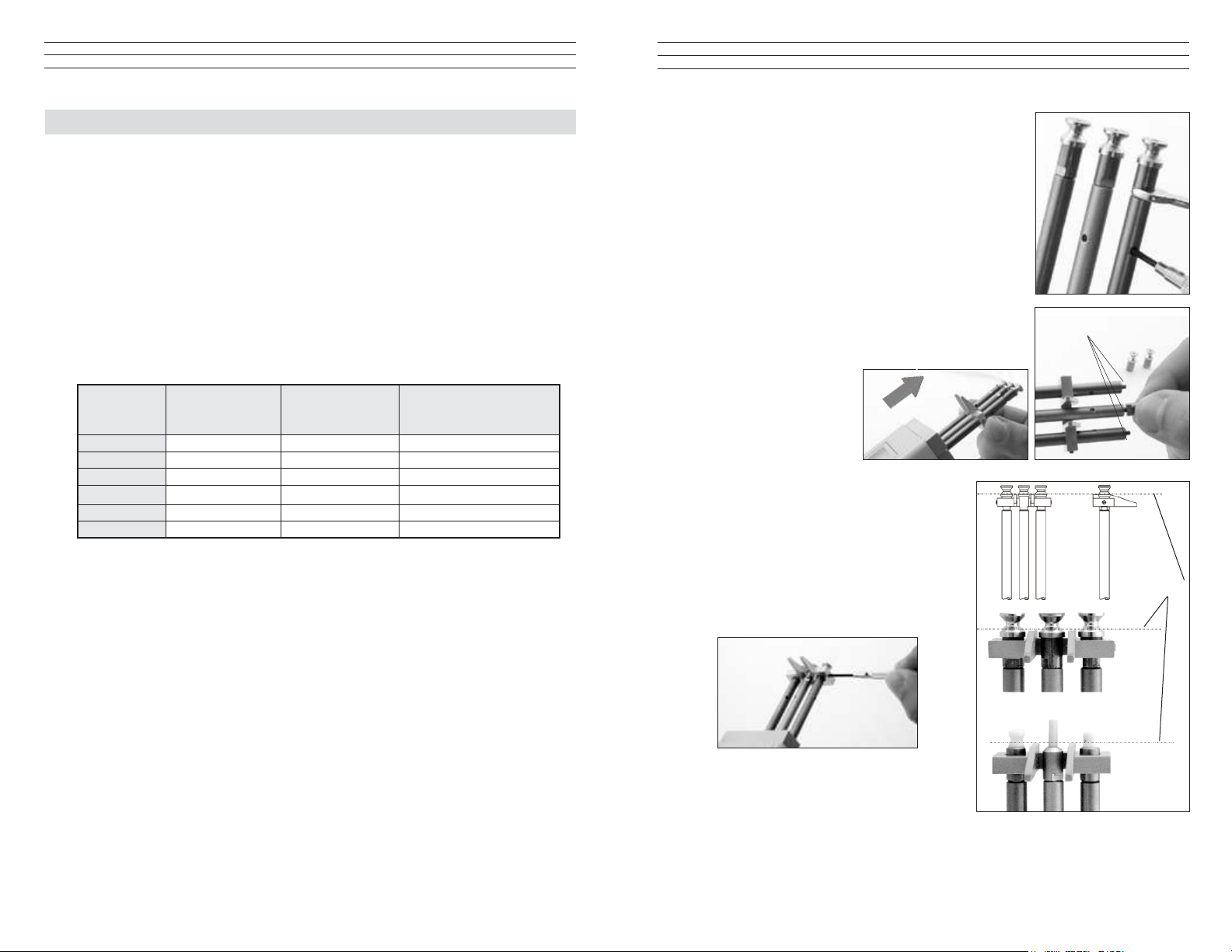
3. Unscrew and remove the GUIDE ROLLERS (2)
using the supplied open-end wrench (4mm jaw width).
Note: Should any of the three threaded studs be damaged,
replace it with one of the threaded studs supplied with the
new rollers.
4. Carefully screw the new GUIDE ROLLERS onto
the ROLLER SHAFTS.
5. Carefully tighten the new rollers with the open end
wrench until hand tight.
Note: When loosening or tightenng the rollers, steady
the roller bolt with the supplied screwdriver to prevent
the ROLLER SHAFTS from being twisted off.
6. Slide the FILAMENT
GUIDE up the roller
shafts in the direction
of the arrow.
7. Push the FILAMENT GUIDE upwards far
enough to ensure that the rollers do not rub
against the FILAMENT GUIDE and that
the process material can slide unhindered
from the FILAMENT GUIDE into the
roller grooves.
8. Tighten the SETSCREWS (2) with the
supplied screwdriver (1.5mm blade).
ROLLER SHAFTS
Ideal line
Delivery includes:
1 Tension meter
1 AC-adapter with 3 country-specic adapters (EU/USA/UK)
1 Open end-wrench (4mm jaw width)
1 Screwdriver (1.5mm blade width)
1 Operating Instructions
1 Carrying case
– 2 –
– 19 –
Page 3
10.0 APPENDIX - REPLACING THE ROLLERS/CERAMIC PINS
GUIDE ROLLERS (2x)
MEASURING ROLLE
2.0 OVERVIEW
You should regularly inspect the rollers to assure that they are running easily and
smoothly. You can replace the rollers yourself, as necessary, by following the directions
in this section. Please indicate the tension meter model and the serial number (given on
the rear side of the tension meter) in your spare-parts order.
Model ID
Model: 03/04
ETMB-100
# 400 - 88888
Serial number
FILAMENT GUIDE
R
ROLLER SHAFTS (2x)
Procedure
1. Remove the FILAMENT GUIDE by loosening
the SETSCREWS (2) using the
supplied screwdriver (1.5m blade width).
GRUB SCREWS (2x)
NOTE: Replacing rollers with
ceramic pins or ceramic pins with
rollers can only be performed at
the manufacturer’s facility.
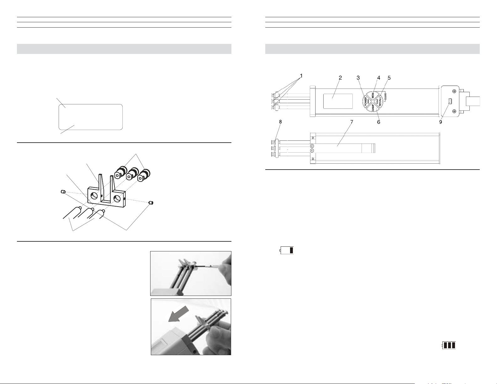
2.1 Operating Elements
1 ROLLERS or ceramic pins
2 DISPLAY
3 POWER / ZERO key
4 MEM key
5 RECALL / HOLD key
2.2 Battery Management & Charging
The tension meter has a built-in rechargeable LiPo battery, which has been charged at
the factory. The tension meter can only be switched on if the battery has enough charge.
If the instrument does not power up or if the battery level indicator shows only one bar
after power-up the battery needs to be recharged.
NOTE: To ensure maximum battery life, avoid discharging it completely or charging it
frequently for short periods. The battery should not be stored for a prolonged time when
empty. After a maximum storage period of one year, the battery has to be recharged.
6 DAMP key
7 LEVER
8 FILAMENT GUIDE
9 USB output (for connecting
the AC adapter
2. Slide the FILAMENT GUIDE down the
ROLLER SHAFTS in the direction of the
arrow.
–18 –
Charging the Battery
NOTE: The battery must be charged at a temperature between +5 °C and
+45 °C. Before connecting the AC adapter, verify that the supply voltage is
correct (100 V – 240 V). Electromatic provides no warranty or liability for
damage resulting from the use of AC adapters from other manufacturers.
To charge the battery, connect the cable of the AC adapter to the USB output. When
the battery is fully charged, the battery level indicator will show 3 bars
The charging time is approx. 3 ½ hours. Battery overcharging is not possible.
– 3 –
.
Page 4
2.3 Turning the Power On and Off
Power On: Press the POWER key until the DISPLAY momentarily shows the tension
range and the software version, e.g. E 1.0, followed by random values or “0.”
Auto Power Off: The tension meter switches off automatically after
3 minutes of non-use.
Manual Switch-Off: Press the POWER key for 5 seconds.
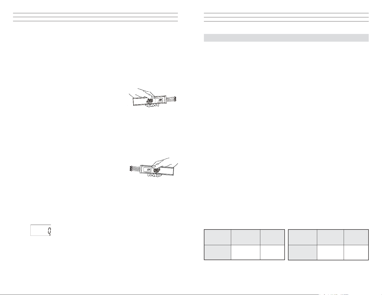
2.4 Reversing the Display
When you shift the tension meter from the right to the left
hand, you can rotate the readings on the DISPLAY by
180°.
Measuring with the left hand:
If you would like to use the left hand for measuring, you should reverse the readings on
the DISPLAY to make them easier to read.
1. Tension meter switched off as described in Chapter 3.3.3.
2. Press and hold the DAMP and POWER keys until the DISPLAY shows the
readings the other way around.
Measuring with the right hand:
1. Tension meter switched off as described above
2. Press and hold the DAMP and POWER keys until
the DISPLAY shows the readings in the default
(right-handed) orientation.
2.5 Selecting the Unit of Measure
You can set the ETMB to the cN or g unit of measure, depending on the required tension
range. The default setting is cN.
1. Tension meter switched off as described aboveTo select the unit of measure:
2. Press and hold the RECALL and POWER keys until the new unit of measure
is indicated on the DISPLAY.
9.0 SPECIFICATIONS
Calibration According to factory procedure
Units of Measure cN / g, user selectable
Accuracy ± 1% FS* ± 1 digit (typical ± 0.5% FS*)
Overrange 10% FS*, without accuracy guarantee
Overload Protection 200% FS*
Measuring Principle Strain gauge bridge
Meas. Roller Deflection 0.5 mm, max.
Signal Processing Digital, 24 bit A/D converter
Damping Adjustable electronical (averaging)
Meas. Frequency Approx. 1 kHz internal
Display Update Rate 2x per sec.
Display 4-digit LCD, 11 mm high
Memory Average, last value, maximum, minimum, MAX
MIN
PEAK
Temperature Coefficient Gain: less than ± 0.01% FS*/°C
Converter Frequency 30 Hz
Temperature Range 10 - 45° C
Air Humidity 85% RH, max.
Auto Power Off Automatical after approx. 3 min. of non-use
Power Supply LiPo accumulator (60 h continouse use, 3 ½ h charging
time) and AC adapter 100 ... 240 V AC with country specic adapters (EU/USA/UK)
Housing Material Aluminium prole with plastic outer casing (PVC)
Housing Dimensions 197 mm x 58 mm x 47 mm (L x W x H)
Weight (net /gross) Approx. 340 g / 1250 g
*FS = Full Scale
ETMB Guide Rollers: ETMPB Guide Pins:
V - grooved
Standard 2000
Line Speed
m/min max.
Roller
Material
Aluminium
hard
chromed
V - grooved
Standard 6000
Line Speed
m/min max.
,
PEAK
Pin
Material
Oxide
ceramic
– 4 –
– 17 –
Page 5

8.3 Restoring Factory Calibration
You can restore the factory calibration at any time with the following procedure:
1. Switch off the tension meter.
2. Press and hold the MEM and POWER keys until the Display shows E-0 cN .
3. Release rst the POWER key and then the MEM key.
4. Press and hold the DAMP and RECALL keys, then additionally
press and hold MEM until the Display shows - - - -cN .
The factory calibration is restored.
5. Release the DAMP, RECALL and MEM keys.
6. Press the POWER key. The instrument switches off.
E-0
D cN
----
D cN
2.6 Zero Adjustment of the Measuring Position (Auto Zero)
A Zero Adjustment is automatically carried out for the current measuring postion.
A Zero Adjustment must be carried out whenever the tension meter
does not display “0” in measuring position. The process material must
not yet be inserted!
Procedure:
1. Switch on the tension meter as described in Sec 2.3.
2. Select the unit of measure as described in Sec 2.5.
Do not insert the process material.
3. Hold the tension meter in the desired measuring position. Be careful to hold the
instrument absolutely steady.
4. Press the POWER key.
The DISPLAY momentarily shows and then switches to .
The tension meter is now adjusted for the new material path and is ready to measure.
– 16 –
– 5 –
Page 6

3.0 REMOVING AND REMOUNTING THE FILAMENT GUIDE
The tension meter is supplied with a FILAMENT GUIDE for fast and easy material
acquisition. For application in hard-to-reach areas with limited access space, you can
remove the FILAMENT GUIDE.
GUIDE ROLLERS (2x)
FILAMENT GUIDE
MEASURING
GRUB SCREWS (3x)
ROLLER SHAFTS (2x)
Removal Procedure
1 Loosen the SETSCREWS (2x) with the supplied screwdriver (1.5 mm blade).
2. Unscrew and remove the GUIDE ROLLERS (2x) with the supplied open end
wrench (jaw width 4 mm).
3. Slip the FILAMENT GUIDE off the ROLLER SHAFTS.
4. Screw the GUIDE ROLLERS (2x) back onto the ROLLER SHAFTS and carefully
tighten using the supplied open end wrench (jaw width 4 mm) until hand-tight.
Remounting Procedure
1. Unscrew and remove the GUIDE
ROLLERS (2x) with the supplied
open end wrench jaw width 4 mm).
2. Slip the lament guide on to the
ROLLER SHAFTS.
3. Screw the GUIDE ROLLERS (2x)
back on to the ROLLER SHAFTS
and carefully tighten them using the supplied open end wrench (jaw width 4 mm)
until hand-tight.
4. Push the FILAMENT GUIDE forward far nough to ensure that the rollers do not rub
against the FILAMENT GUIDE and that the process material can slide unhindered
from the FILAMENT GUIDE into the roller grooves (g. CENTER LINE).
5. Carefully tighten the SETSCREWS (2x) with the supplied screwdriver
(blade width 1.5 mm) until hand-tight.
SETSCREWS (2x)
CENTER LINE
ROLLER
o3rd calibration point:o
1. Repeat steps 1 through 4 from the preceding procedure using a weight which
corresponds to 70% of the tension range
2. Press the RECALL key. As long as the RECALL key is
depressed, the DISPLAY shows a decimal value which is
higher than the second decimal value, e.g., 8000. This decimal
value may vary from instrument to instrument. Write down the
value.
3. Release the RECALL key when the value shown on the
DISPLAY is stable (the reading might uctuate greatly).
The DISPLAY shows E 100
o4th calibration point:o
1. Repeat steps 1 through 4 from the preceding procedure using a weight which
corresponds to 100% of the tension range
2. Press the RECALL key. As long as the RECALL key is
depressed, the DISPLAY shows a decimal value which is
higher than the third decimal value, e.g., 9500. This decimal
value may vary from instrument to instrument. Write down the
value
3. Release the RECALL key when the value shown on the DISPLAY is stable (the
reading might uctuate greatly).
4. Press and then release the RECALL key. the DISPLAY switches off after
approximately 1 second. The new calibration is stored.
5. Press the POWER key. the instrument switches off.
6. Verify the new calibration, following the directions in Sec. 7.0 If this procedure
shows a deviation, you can recalibrate the tension meter again or restore the factory
calibration as described in Sec. 8.3.
If the verication of the calibration according Sec.7.0 shows a deviation beyond
the allowable tolerance and a reliable operation is no longer allowed, the
instrument has to be returned to Electromatic for factory recalibration.
8000
E 100
9500
– 6 –
– 15 –
Page 7

2. Release the RECALL key when the value shown on the Display is fairly stable
(the reading might uctuate greatly).
3. The Display shows E –10
o1st calibration point:o
1. Hang a weight which
corresponds to 10% of
the tension range from the
measured material, vertically,
as shown.
2. Press the LEVER down
all the way. Thread the
PROCESS MATERIAL
through the MEASURING
and GUIDE ROLLERS.
Slowly release pressure on
the LEVER until the GUIDE ROLLERS return to their original position.
3. Before starting the calibration, move the instrument slowly up and down to
compensate for possible mechanical friction losses and thus ensure repeatability of
the measurements.
4. Press the RECALL key. As long as the RECALL key is
depressed, the DISPLAY shows a decimal value which is
higher than the rst decimal value, e.g., 3500. This decimal
value may vary from instrument to instrument.
Write down the value
5. Release the RECALL key when the value shown on the
DISPLAY is stable (the reading might uctuate greatly).
The DISPLAY shows
o2nd calibration point:o
1. Repeat steps 1 through 4 above using a weight which corresponds to 40% of the
tension range
2. Press the RECALL key. As long as the RECALL key is
depressed, the DISPLAY shows a decimal value which is
higher than the second decimal value, e.g., 6000. This decimal
value may vary from instrument to instrument. Write down the
value
3. Release the RECALL key when the value shown on the
DISPLAY is stable (the reading might uctuate greatly).
The DISPLAY shows E –70
MEASURING
ROLLERS
E –10
PROCESS
MATERIAL
WEIGHT
3500
E –40
6000
E –70
4.0 TAKING A MEASUREMENT
NOTE: Before taking a measurement, be sure that the correct unit of
measurement (g or cN) has been selected and a zero adjustment
has been performed.
4.1 Inserting the process material
1. Press the LEVER to tilt the outer GUIDE ROLLERS sidewards.
2. Thread the PROCESS
MATERIAL through the
MEASURING and
GUIDE ROLLERS
(lament guide).
3. Slowly release pressure on
the LEVER until the GUIDE
ROLLERS returnto their
original position.
NOTE: It is important to
assure that the PROCESS
MATERIALruns smoothly
between the MEASURING
and GUIDE ROLLERS.
4.2 Measuring the process
material
The DISPLAY now shows the
measured tension values. Error
messages which might be displayed
are described in Sec. 6.5.
4.3 Removing the process material
1. Press the LEVER and remove the PROCESS MATERIAL.
2. Slowly release pressure on the LEVER until the GUIDE ROLLERS
return to their original position.
– 14 –
– 7 –
Page 8

5.0 DAMPING MODE
8.0 CALIBRATION
The tension meter is equipped with an electronic damping that ensures steady readings
when tension ucutates. This is achieved by averaging the measured values at the preset
update rate.
5.1 Switching On the Damping Mode
NOTE: Before switching on the damping mode, it is recommended that you measure
the rst values without damping enabled.
1. Insert process material as described in section 4.1.
2. Press and hold the DAMP key. The display shows the currently set damping factor.
3. Release the DAMP key. The display shows DAMP below the
currently measured value.
5.2 Switching Off the Damping Mode
1. Press and release the DAMP key. If display shows only the
currently measured value, damping is off.
5.3 Changing the Damping Factor
The tension meter is factory preset to a damping factor of 12. The tension values are
thereby averaged for the display in the following way:
12 old values + 4 new values
16
The damping factor can be modied in 15 steps from 01 = low damping:
1 old value + 15 new values
16
to 15 = high damping:
15 old values + 1 new value
16
1. Switch on the tension meter
2. Press and hold the DAMP key. The Display shows the set damping factor.
3. You can now increase the damping factor by pressing the MEM key and
decrease it by pressing the RECALL key.
4. Release the DAMP key to return to the measuring mode.
NOTE: The selected damping factor remains stored in memory even
after the gauge is turned off.
22.1
D cN
22.1
D cN
8.1 Dynamic Calibration of the ETX
All tension meters are calibrated with standard materials—such as polyamide
monolament (PA)—ccording to the factory procedure. The diameters are given in
section 1.0. In 95% of all industrial applications, the factory calibration has been proven
to provide the best results and is used for comparative purposes. The basic setup for a
dynamic calibration is shown below.
Line speed Vmax. = ETMB 100 m/min
Vmax. = ETMPB 60 m/min
Hang twice the weight (pulley effect) which corresponds to
the tension to be measured from the measured material,
vertically, as shown here. Please keep in mind to include
the weight of the lower deection pulley when you calculate the suspended weight. Pay attention to the correct
unit of measure cN.
NOTE: The gauge has been calibrated dynamically according to factory procedure.
Therefore, differences may occur between static and dynamic readings.
8.2 Static Calibration
NOTE: The tension meter is factory calibrated for a vertical material path
Recalibration thus also has to be carried out with a vertical material path.
Before beginning:
Acquire one cN weight each (or several weights adding up to the required value),
corresponding to 10%,40%, 70% and 100% of the tension range. Make sure the tension
meter is switched off and that no process material is inserted between the rollers.
To select the calibration mode:
1. Press and hold the MEM and POWER keys until the Display
shows E –0
2. Release rst the POWER key and then the MEM key.
To calibrate the zero point:
1. Press the RECALL key. As long as the RECALL key is
depressed, the Display shows a random decimal value between
–2000 and 2000, e.g. 800 cN. This decimal value may vary from
instrument to instrument.Write down the decimal value.
NOTE: If the value is outside this range, calibration cannot be guaranteed.
E –0
800
– 8 –
– 13 –
Page 9

7.0 STATIC VERIFICATION OF MEASURING ACCURACY
6.0 STORING AND RECALLING TENSION VALUES
All tension meters are calibrated with standard materials—such as polyamide
monolament (PA)—according to the factory procedure. The diameters are given in
section 1.0. Any difference in process material size and rigidity from the standard
material may cause a deviation of the accuracy.
In 95% of all industrial applications, the factory calibration has been proven to provide
the best results and is used for comparative purposes.
NOTE: Before beginning, make sure that the tension meter is factory calibrated
for a vertical material path. The required reference weight is available.
Verication procedure:
1. Switch on the tension
meter.
2. Hang a weight
which corresponds
to the tension to be
measured from the
measured material,
vertically, as shown.
NOTE: Pay attention to the correct unit of measure cN or g (gram).
3. Press the LEVER down all the way down and thread the process material through
the MEASURING and GUIDE ROLLERS as described in section 4.1, then
slowly release pressure on the LEVER until the GUIDE ROLLERS return to
their original position.
4. Before verifying the calibration, move the instrument slowly up and down to
compensate for possible mechanical friction losses and thus ensure repeatability of
the measurements.
5. The tension value shown on the Display should be equal to the value of the
suspended weight (pay attention to the measuring units).
If this procedure shows a deviation, you can recalibrate the instrument following the
directions in Sec 8.0
MEASURING- and
GUIDE ROLLERS
Process
material
The tension meter features a data logger which stores the followng data obtained during
a measuring period:
Average value
Last value
Maximum value (MAX),
Minimum value (MIN),
Minimum peak value (MIN PEAK)
Maximum peak value (MAX PEAK)
NOTE: The measured data remain stored in the ETMB memory even after the
instrument is switched off.
6.1 Storing Tension Values
NOTE: The stored tension values remain stored in the ETMB memory even after the
instrument is switched off.
1. Turn off the tension meter.
2. Insert the process material.
3. Press the MEM key to start the measuring period.
While the tension data are stored, the MEM indicator blinks on the
DISPLAY and the currently measured value is displayed.
When you want to end the measuring period, press the MEM key once again. Data
logging is stopped. The DISPLAY shows MEM and the current reading.
6.2 Recalling Stored Tension Values
1. Be sure that the tension meter is ON.
NOTE: You can end recall at anytime by pressing the POWER key.
2. Press the RECALL key. The display blinks, showing
the average value of the measuring period and the
indicated symbol.
3. Press the RECALL key. The display blinks, showing the
last value of the measuring period (no symbol).
4. Press the RECALL key. The display blinks, showing
the maximum value of the measuring period and the
indicated symbol.
5. Press the RECALL key. The display blinks, showing
the minimum value of the measuring period and the
indicated symbol.
D cN
MEM
D cN
D cN
D cN
D cN
3
22
23
24
21
– 12 –
– 9 –
Page 10

6. Press the RECALL key. The display blinks, showing the
maximum peak value of the measuring period and the
indicated symbol.
7. Press the RECALL key. The display blinks, showing the
maximum peak value of the measuring period and the
indicated symbol.
8. Press the RECALL key. The tension meter switches back to
the measuring mode. The display shows MEM and the current
reading.
The tension meter is ready for a new measuring period.
6.3 Clearing Tension Values Stored In Memory
If values are stored in the tension meter memory, the DISPLAY
hows with the MEM indicator.
1. To clear the memory, simultaneously press the MEM and
RECALL keys.
and all values stored inmemory are deleted.
6.4 Memory Function HOLD
When the tension meter memory is empty, you can retain the last reading on the Display
by using the memory function HOLD.
To retain the last reading:
Press the RECALL / HOLD key once for about 1 second. The
Display shows the last readingand the “:” colon symbol.
To switch back to measuring mode:
Press the RECALL / HOLD key once for about 1 second.The tension meter switches
back to measuring mode.
The MEM indicator disappears
26
D cN
19
D cN
3
D cN
MEM
3
D cN
MEM
3
D cN
MEM
2:2.8
D cN
MEM
2. The Display shows -E.E. The lower limit of the tension range
has fallen below by more than 10%.
Properly insert the process material.
OR
AUTO ZERO is no longer possible.
Recalibrate the instrument following the directions inSec. 8.0.
–EE
D cN
6.5 Error Messages
1. The Display shows EEE. The upper limit of the tension range was
exceeded by more than 10%. Reduce the line tension.
OR
AUTO ZERO is no longer possible.
Recalibrate the instrument following the directions in Sec. 8.0.
– 10 –
EEE
D cN
– 11 –
Page 11

ETMB1110
CHECK•LINE
BY ELECTROMATIC
Tension Meters
ETMB-ETMPB
®
CHECK•LINE
INSTRUMENTS
®
ELECTROMATIC
E Q U I P M E N T C O., I N C.
600 Oakland Ave., Cedarhurst, NY 11516 – USA
TEL: 516-295-4300 • FAX: 516-295-4399
Operating Manual
 Loading...