

Page 1

Model ESMH
MOTORIZED FORCE MEASUREMENT TEST STAND
User’s Guide
Page 2
Model ESMH Motorized Test Stand
User’s Guide
Thanks!
Thank you for purchasing a Mark-10 Model ESMH motorized test
stand. We are confident that you will get many years of great service
from this product.
Mark-10 test stands and load frames are ruggedly built for many years
of service in laboratory and industrial environments.
This User’s Guide provides unpacking, setup, and operator instructions,
along with specifications and dimensions. For additional information or
answers to your questions, our technical support and engineering
teams will be eager to help you.
Thank you again for your purchase and happy testing!
TABLE OF CONTENTS
INTRODUCTION .........................................................................2
UNPACKING ..............................................................................2
SAFETY TIPS..............................................................................3
SETUP.........................................................................................3
OPERATION ..............................................................................5
SPECIFICATIONS.......................................................................7
DIMENSIONS..............................................................................8
TEST STANDS BY MARK-10 .....................................................9
FORCE GAUGES BY MARK-10 ...............................................10
WARRANTY ..............................................................................10
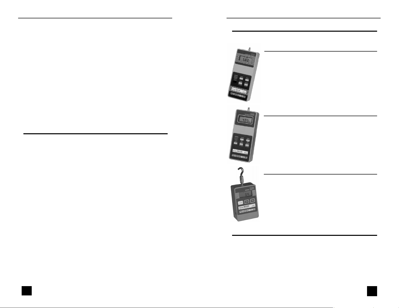
FORCE GAUGES BY MARK-10
Capacities from 0.12 lb (0.5 N) to 1,000 lb (5,000 N)
Force Gauges Series EG
•
Reversible aluminum housing for hand-held use or stand
mounting
•
Three units of measurement: lb, kg, N
•
Programmable initial status of units and mode of operation
•
Automatic peak memory
•
Push-button calibration
•
Battery or AC operation with programmable automatic shutoff
•
Permanent configuration memory
•
Optional RS-232, Mitutoyo and analog outputs
Force Gauges Series BG
•
RS-232, Mitutoyo and analog outputs
•
GCL – Gauge Control Language for full control of all functions
•
Automatic timed output on RS-232
•
Dual set points with outputs
•
General purpose I/O for external device control
•
Programmable analog and digital filters
•
Averaging mode for obtaining average force readings over
time
Force Gauges Series MG
•
Low cost and small size
•
Aluminum housing is reversible for hand-held use or test stand
mounting
•
Peak memory for tensile and compressive loads
•
Selectable units of measurement programmable auto shutoff
•
Push-button calibration
•
IPM - Intelligent Power Management system for reliable operation
(in addition to EG features)
1
WARRANTY
Mark-10 Corporation expressly warrants to its buyer for three (3) years from the
date of delivery that the goods sold are free from defects in workmanship and
materials. Mark-10 Corporation will, at its option, repair or replace or refund the
purchase price of goods found to be defective. This remedy shall be the buyer’s
sole and exclusive remedy. Any modification, abuse, exposure to corrosive environment or use other than intended will void this warranty. This warranty is in lieu
of all other warranties, including implied warranties of merchantability and fitness
for an intended purpose. In no event shall Mark-10 Corporation be liable for any
incidental and consequential damages in connection with goods sold or any part
thereof.
10
Page 3

Model ESMH Motorized Test Stand
User’s Guide
TEST STANDS BY MARK-10
Manual and motorized, up to 1,000 lb and 100 lbin
TSAH
Manual, Force
TSTM
Motorized, Torque
100 lbin
TSCH
Manual, Force
Hand wheel
1,000 lb
ES10
Manual, Force
Lever
100 lb
Lever
750 lb
Manual, Force
TSF
Manual, Force
Hand wheel
1,000 lb
Manual, Force
ES20
Manual, Force
Hand wheel
100 lb
TSB
Lever
100 lb
TSA
Lever
750 lb
INTRODUCTION
The ESMH motorized test stand is a horizontal force measurement
tester designed to test up to 50 lb [250 N] of tensile or compressive
force. The ESMH works in conjunction with a force gauge and gripping
fixtures. Common applications include peel testing, small spring testing, coefficient of friction testing, and other product performance testing.
UNPACKING
Carefully unpack the contents and inspect for any damage. Check the
contents to ensure that you have received all of the items listed below:
Quantity Item
1 Test stand
1 Controller
1 Power cord
1 Grip mounting plate
4 Screws for grip mounting plate
4 Thumb screws for force gauge mounting
1 User’s guide (this booklet)
1 Tool kit
1 Accessories set (small hook, medium hook, 2” diameter
compression plate, 2” extension rod, and #10-32 coupler)
9
TSFH
Manual, Force
Hand wheel
1,000 lb
Optional items
Part No. Description
ESMH001 Digital travel display kit (with separate user’s guide)
ES30
Manual, Force
Hand wheel
200 lb
ESM
Motorized, Force
200 lb
2
Page 4

Model ESMH Motorized Test Stand
SAFETY TIPS
■
Wear eye and face protection when testing. Although the ESMH
has relatively slow moving mechanisms, be aware of the dangers
posed by potential energy that can accumulate in a sample during
testing.
■
Keep away from the moving parts of the test stand.
■
Never operate the test stand if there is any visible damage to the
power cord or the control unit. The ESMH is powered by 110/220V
AC current that is present in both the power cord and the control
unit. Any contact with this high voltage can cause serious injury or
even death.
■
Ensure that the control unit is kept away from water or any other
liquids at all times.
■
Make sure the electrical outlet powering the test stand has local
earth ground (3-hole outlet).
■
Opening up the cover of the control unit is not recommended, as
there are no user-serviceable parts inside. If you wish to open it, be
sure to disconnect power before doing so. If any repairs are
needed, contact Mark-10 or your distributor.
SETUP
Mounting to a workbench
Place the ESMH on a clean, flat and level work area that meets the
criteria outlined in the work area safety instructions. For accurate readings, the area should be free of vibrations.
If desired, the test stand can be mounted to the work area with four
5/16 screws.
User’s Guide
DIMENSIONS
#10-32 UNF
X15
1.30 [33.0]
7.25 [184.1]
5.25 [133.4]
0.50 [12.7]
2.00 [50.7]
0.50 [12.7]
2.65 [67.3]
0.32 [8.1]
13.10 [330.0]
MAX (BG/EG)
20.00 [507.9]
23.25 [590.6]
13.50 [343.0]
MAX (MG)
OPTIONAL TRAVEL DISPLAY
IN [MM]
2.23 [56.6]
2.63 [66.7]
2.23 [56.6]
3
8
Page 5

Model ESMH Motorized Test Stand
About the digital travel display (optional)
The travel display covers 12” of travel with a 5digit display (0.0005” resolution) and a computer
interface for automated data collection. Use cable P/N 09-1066 to output data to a PC.
Complete instructions are provided in a separate
user’s guide (included with the digital travel display).
SPECIFICATIONS
Load capacity: 50 lb [250 N]
Speed range: 0.2-50 in/min [5-1270 mm/min]
Speed accuracy: ±5% of setting, ±0% variation with load
Maximum travel: 13.0 in [330.2 mm]
Maximum travel w/travel display: 12.0 in [304.8 mm]
Power: Universal input 80-240 VAC, 50/60 Hz
Fuse type: 1.2 A, 250V, 3AG SLO BLO
Weight (test stand only): 17 lb [7.7 kg]
Controller weight: 2.7 lb [1.2 kg]
User’s Guide
Mounting force gauges
To mount a force gauge, it is necessary
to temporarily remove the gauge
adapter from the crosshead. Loosen the
two 5/16 screws (shown at left) using
the included tool kit. Then, mount the
gauge to the adapter using the four included gauge mounting screws. After
the gauge is mounted to the adapter,
mount the adapter back onto the crosshead with the 5/16 screws.
Mounting grips and fixtures
The ESMH includes a loading plate to
which a grip or fixture may be mounted.
This plate can be mounted to the end of
the stand with four screws (shown at
left). Before mounting the loading plate,
mount the grip or fixture to it, using the
matrix of tapped holes if required.
Setting up the controller
Plug the controller cable into the 9-pin male connector located beside
the motor. See illustration below.
Connector for optional set point cable /
overload protection module
7
Connector for controller
4
Page 6

Model ESMH Motorized Test Stand
User’s Guide
OPERATION
Using the controller
Top View
7
1
2
3
1. SPEED CONTROL DIAL
Adjust speed by turning the dial 0.2 – 50.0 in/min [5 – 1270 mm/min].
2. LEFT
Press and hold to move the crosshead to the left, producing compressive force.
Release button to stop motion.
3. RIGHT
Press and hold to move the crosshead to the right, producing tensile force. Release
button to stop motion.
4. CONTROLLER CABLE
Plug this cable into the lower connector on the test stand, adjacent to the motor.
5. POWER SWITCH
Use this switch to turn on and turn off power to the load frame. Power is indicated
by illuminated indicators on the face of the controller and load frame.
6. POWER PLUG RECEPTACLE
Plug the power cord in here.
7. FUSE
1.2 A, 250V, 3AG SLO BLO
4
Rear View
4
7
5
6
Powering up
Plug the power cord into the controller and the other end into a wall
outlet. Then turn on power with the power switch (see Page 5).
Reading the indicators
POWER
Power is indicated by an
illuminated indicator.
Indicates a limit condition
LEFT LIMIT
in compression.
RIGHT LIMIT
Indicates a limit condition in
tension.
Using the limit switches
Limit switches are included to
allow the operator to set travel
limits during testing. This feature
is particularly useful for spring
testing, elongation testing, and
other applications where stopping
at a predetermined position is a
requirement.
The limit switches are located in
the rear of the load frame. Their positions can be adjusted by loosening
the thumbscrews (shown at left), sliding them to either side, and retightening. During testing, when a travel limit has been reached, an
indicator will be illuminated (see illustration above) and the crosshead
movement will stop.
Note: To maintain smooth functioning of the stand, avoid overloads.
5
6
 Loading...