

Page 1

Force Test Stands Series
MODELS ESM & ES30
User’s Guide
ES
Page 2
Models ESM & ES30
User’s Guide
Thanks!
Thank you for purchasing a Mark-10 Series ES Force Meas urement
Test Stand. We are confident that you will get many years of great
service from this produc t .
Mark-10 test stands are ruggedly built for many years of service in
laboratory and industrial environments.
This User’s Guide provides unpack ing, setu p, and operat or instruc tions
for the Model ES30 and Model ESM Force Measurement Test Stands.
Dimensions and specificat ions are also provided. For additional information or answers to your questions, our technic al support and engineering teams are eager to help you.
Thank you again for your purchase and happy testing!
TABLE OF CONTENTS
LIST OF INCLUDED ITEMS .......................................................2
UNPACKING AND SETTING UP ...............................................2
MODEL ESM ..............................................................................3
Safety Tips ............................................................................3
Setup ....................................................................................3
Operation ..............................................................................4
Specifications .......................................................................5
Dimensions ...........................................................................6
MODEL ES30 .............................................................................7
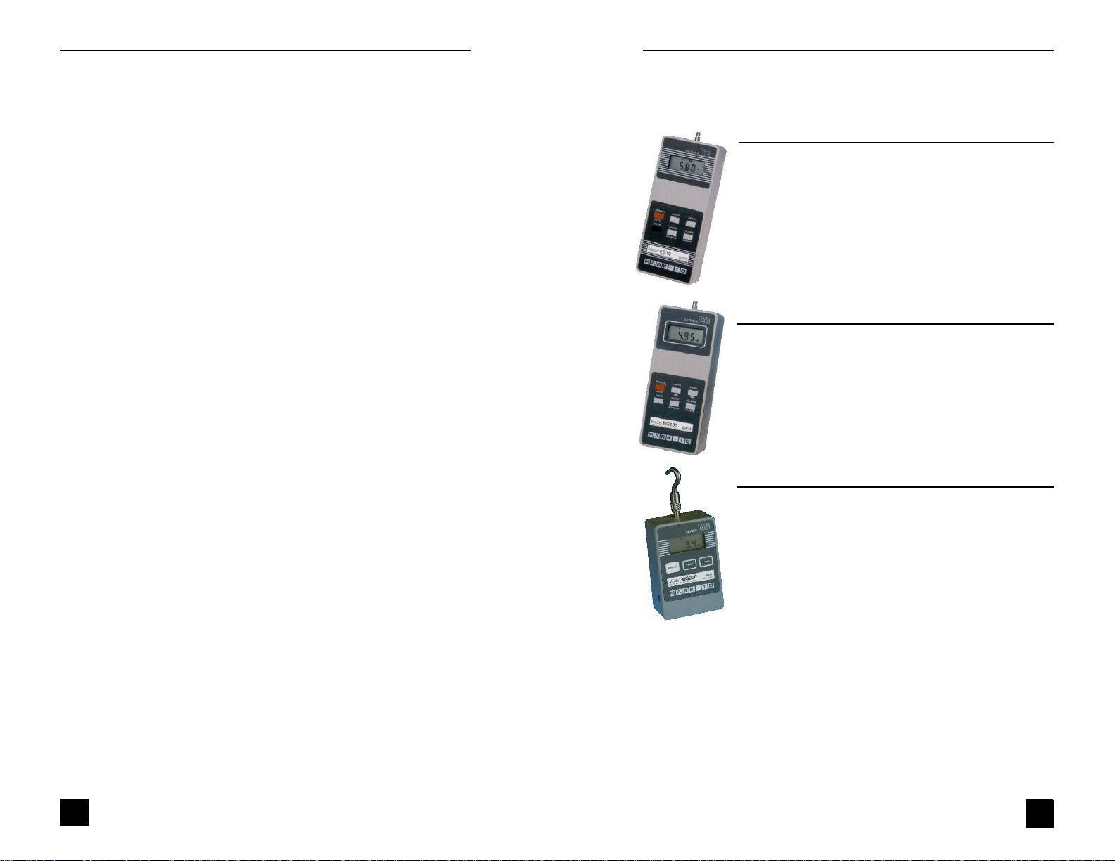
FORCE GAUGES BY MARK-10
Capacities from 0.25 lb (1 N) to 500 lb (2500 N)
Force Gauges Series EG
•
Reversible aluminum housing for hand-held use or stand
mounting
•
Three units of measurement: lb, kg, N
•
Programmable initial status of units and mode of operation
•
Automatic peak memory
•
Push-button calibration
•
Battery or AC operation with programmable automatic shutoff
•
Permanent configuration memory
•
Optional RS-232, Mitutoyo and analog outputs
Force Gauges Series BG
•
RS-232, Mitutoyo and analog outputs
•
GCL – Gauge Control Language for full control of all functions
•
Automatic timed output on RS-232
•
Dual set points with outputs
•
General purpose I/O for external device control
•
Programmable analog and digital filters
•
Averaging mode for obtaining average force readings over
time
Force Gauges Series MG
•
Low cost and small size
•
Aluminum housing is reversible for hand-held use or test stand
mounting
•
Peak memory for tensile and compressive loads
•
Selectable units of measurement programmable auto shutoff
•
Push-button calibration
•
IPM - Intelligent Power Management system for reliable operation
(in addition to EG features)
Operation ..............................................................................7
Dimensions ...........................................................................8
Specifications .......................................................................8
OTHER TEST STANDS BY MARK-10 .......................................9
FORCE GAUGES BY MARK-10 ..............................................10
WARRANTY .............................................................................10
1
WARRANTY
Mark-10 Corporation expressly warrants to its buyer for three (3) years from the date
of delivery that the goods sold are free from defects in workmanship and materials.
Mark-10 Corporation will, at its option, repair or replace or refund the purchase price
of goods found to be defective. This remedy shall be the buyer’s sole and exclusive
remedy. Any modification, abuse, exposure to corrosive environment or use other
than intended will void this warranty. This warranty is in lieu of all other warranties,
including implied warranties of merchantability and fitness for an intended purpose.
In no event shall Mark-10 Corporation be liable for any incidental and consequential
damages in connection with goods sold or any part thereof.
10
Page 3

Models ESM & ES30
OTHER TEST STANDS BY MARK-10
Manual and motorized, up to 1,000 lb and 100 lbin
TSAH
Manual, Force
Lever
750 lb
Manual, Force
TSB
Lever
100 lb
User’s Guide
LIST OF INCLUDED ITEMS
Quantity Item
1 Force measurement test stand
1 Remote console (ESM, only)
1 Power cord (ESM, only)
1 User’s guide (this booklet)
4 Thumb screws for gauge mounting
1 Mounting hole drill template
1 Accessories set (small hook, medium hook, 2” diameter
compression plate, 2” extension rod, and #10-32 adapter)
TSTM
Motorized, Torque
100 lbin
TSCH
Manual, Force
Hand wheel
1,000 lb
ES10
Manual, Force
Lever
100 lb
TSF
Manual, Force
Hand wheel
1,000 lb
ES20
Manual, Force
Hand wheel
100 lb
Manual, Force
TSA
Lever
750 lb
Optional items
Part No. Description
ESM001 Digital travel display kit
ESM002 Limit switch kit (available for ESM, only)
Carefully unpack the test stand and inspect for any damage. Check
the contents to ensure th at you have rec eiv ed a t es t stand complete
with all accessories – see the above lis t of included items.
9
TSFH
Manual, Force
Hand wheel
1,000 lb
ES30
Manual, Force
Hand wheel
200 lb
TSC
Manual, Force
Hand wheel
1,000 lb
2
Page 4

Models ESM & ES30
User’s Guide
ESM
SAFETY TIPS
•
Wear eye and face prot ec t i on when tes tin g. Alt h ough t he ESM has
relatively slow moving mechanisms, be aware of t he dangers
posed by potential energies that can ac c umula te in t he s ample
during testing.
•
Keep away from the moving parts of the tes t s t a nd.
•
Never operate the test stand if th ere is any visi ble damage t o the
power cord or the control unit. The ESM is powered by 110/220
volts that are present in bot h t he po wer cord and the control unit.
Any contact with this high voltage can ca us e s erious injury or even
death.
•
Ensure that the control unit be kept away from water or any other
electrically conductive liquids at all times.
•
Make sure the electrical outlet powering the test stand has local
earth ground (3-hole outlet).
•
If it is necessary to remove the cover of the control unit or motor
drive, always disconnect power before doing so. Use Mark -10 replacement parts, only, if any repairs are needed.
SETUP
Place the stand on a clean, flat and level work area that meets the criteria outlined in the work area safety instructions . For acc ura te readings, the area should be free of v ib rations.
If desired, the stand can be mounted to the work area with two 5/16
screws. Included is a mounting hole dril l t emplat e f or qui c k s et up . Before the stand can be mounted, t he belt cover surrounding the fine adjustment knob on the right hand side of t he s t an d has to be remov e d.
Using a flat screwdriver, loosen the four captive screws and slide off
the cover.
After the two 5/16 screws holding the sta nd are tig ht , pla c e the belt
cover back into place. While making sure that there is no contact with
the fine adjustment knob, ti ghten the screws in the four corners.
ES30
DIMENSIONS
SPECIFICATIONS
Load capacity 200 lbs. (1000 N)
Maximum travel 13” (228.6 mm)
Loading method Hand wheel
Travel rate 0.05”/rev. (1.27 mm)
Weight (test stand, only) 17 lbs (7.7 kg)
in [mm]
3
8
Page 5

Models ESM & ES30
User’s Guide
ES30
OPERATION
Place the stand on a clean, flat, and level surface. It is recommended
that the stand be mounted to the surface with two 5/16 screws. Use the
mounting hole drill template for quic k se t up. I ns t a ll a f orc e gau ge ont o
the gauge plate with four thumb screws. All Mark -10 f orc e gauges
(except the Series CG) mount directly to the stand without adapters .
Install the necessa ry attach ments and make sure they are secure, safe
to operate, and set up properly for your sample. Then zero out the
force gauge and turn the hand wheel clockwise for compression or
counter-clockwise for tension.
The base is removable so that t he stand may be used as a component
of a larger testing system. Proper care should be taken during installation to avoid injury.
To maintain smooth functioning of the stand, avoid overloads.
Optional Equipment
Digital Travel Display Kit
This position indicator covers 6” of travel per setting with a 5 digit display (0.0005” resolution) and a computer interfac e f or aut omat e d dat a
collection. It may be easily installed by the user.
Motor Drive Ki t
The motor drive kit converts an ES30 manual test stand into an ESM
motorized test stand. T he ki t c ons i s t s of a mot or bl oc k t ha t rep laces the
hand wheel, a remote console and an optional l imit s witc h k it . T he
speed is user selectable f r om 0.5 t o 13 in/m in [1 3 t o 330 mm/min] and
it is load independent. The s ystem is ov erlo ad reg ula te d to 15 0% of full
capacity.
ESM
With the base removed, the ESM can be easily integrated into large
systems such as production lines. In general, the stand can be
mounted on any angle (upside down, for example), alth oug h ex tr a c are
should be taken during installation and operation.
After the stand is in a sta ble and s ec ure position, install a force gauge
with four thumb screws (provided). All Mark-10 gauges (except th e Series CG) mount directly without adapters.
Plug the remote console cable into the 9-pin male connector located
above the motor in the rear of the st and .
Plug the power cord into the remote console and the other side into a
wall outlet.
Turn on the power with the switch located on the remote co ns ol e by the
power cord.
The test stand is now ready for operation.
OPERATION
Using the provided attachme nts , set up your sample, zero out the force
gauge and, if applicable, conn ec t it to a comp ut er or prin t er. When the
gauge and sample are ready for testing, us e th e remot e c on s ole t o operate the test stand. For fine adjustment or otherwise manual testing,
turn the knob on the right hand side of the stand clock wise for compression, counter-clockwise for tension.
Optional Equipment
Limit Switches
Adjust the switches’ vertic a l pos i ti ons by looseni ng an d re-t igh ten ing
the wing screws. A limit condition is indicated by an amber light on
the front surface of eac h s ens o r.
Upper limit switc h – while a limit condition exists, the slider will not
move up
Lower limit switch – while a limit condition exists, the slider will not
move down
7
4
Page 6

Models ESM & ES30
User’s Guide
ESM
Using the Control Unit
UP
Press and hold for tension, release button to stop moti on. Located
on the face of the Control Unit.
DOWN
Press and hold for compression, release button to stop motion. Lo-
cated on the face of the Cont rol Unit.
SPEED CONTROL DIAL
Adjust speed by turning the dial 0. 5 – 13 in/ min [13 – 33 0 mm/ mi n] .
Located on the face of the Contro l Unit.
POWER SWITCH
Use this switch, in the left rear of the Control Unit, to turn on and
turn off power to the test stand . Power is indicated by an amber light
on the face of the Control Unit
POWER PLUG RECEPTACLE
Located in the left rear of the Control Unit. Plug the power cord in
here.
CONTROL CABLE
Plug this cable into th e lower male conne c to r on t he t es t s t and , ad -
jacent to the motor.
ESM
DIMENSIONS
SPECIFICATIONS
Load capacity 200 lbs [1000 N]
Speed range 0.5-13 in/min [13-330 mm/min]
Maximum travel 13.0 in [228.6 mm]
Maximum travel w/options 11.75 in [298.45 mm]
Speed variation with load ±0% (Stepper motor driven)
Speed accuracy ±5% of setting
Overload protection Max. 150% of full capacity
Power Universal input 80-240 VAC, 50/60 Hz
Fuse type 1.2 A, 250V, 3AG SLO BLO
Weight (test stand, only) 20 lbs [9.1 kg]
Control unit weight 2.7 lbs [1.2 kg]
5
in [mm]
6
 Loading...