

Page 1
1
CONTENTS
. . . . . . . . . . . . . . . . . . . . . . . . . . . . . . . . . . . . . . . . . . . . . . . . . . . . . Page
1.0 Introduction . . . . . . . . . . . . . . . . . . . . . . . . . . . . . . . . . . . . . . . . . . . . . . . . . . 02
1.1 Complete Kit
1.2 Unpacking
1.3 Tension Ranges
2.0 Overview . . . . . . . . . . . . . . . . . . . . . . . . . . . . . . . . . . . . . . . . . . . . . . . . . . . .
03
2.1 Operating Elements
2.2 Mounting Special Finger Support
3.0 Taking A Measurement . . . . . . . . . . . . . . . . . . . . . . . . . . . . . . . . . . . . . . . 04
4.0 Verifying Calibration . . . . . . . . . . . . . . . . . . . . . . . . . . . . . . . . . . . . . . . . . .
05
4.1 Frequency of Calibration Verification
4.2 NIST Calibration
5.0 Options . . . . . . . . . . . . . . . . . . . . . . . . . . . . . . . . . . . . . . . . . . . . . . . . . . . . . .
07
5.1 Air Dashpot Damping
5.2 Memory Pointer
6.0 Specifications . . . . . . . . . . . . . . . . . . . . . . . . . . . . . . . . . . . . . . . . . . . . . . . . . 8
6.1 Dimensions
6.2 Ordering Spare Rollers
7.0 Warranty
The device must not be operated in explosion hazard areas
and must not come into contact with aggressive substances.
Tensions that exceed the tension range of the instrument by
more than 100 % may cause permanent damage to the
movement and must be avoided under any circumstances.
6.0 SPECIFICATIONS
Calibration According to factory procedure
eeeeeeeeeeeeee
Accuracy* ± 1% full scale (FS) or ± 1 graduation on scale
Scale diameter 41 mm
Temperature range 45 to 115 °F (10 - 45 °C)
Air humidity 85% RH, max.
Housing material Die-cast aluminum
Housing dimensions 8.6 in x 3.5 in x 1.7 in (188 x 85 x 45mm)
(L x W x H)
Weight (net) Approx. 1.04 lb. (470 g)
Guide rollers V-grooved
Line Speed 2000 m/min max.
Roller Material Standard hardcoated aluminiummmm
mmmmmmmmm
* Using factory standard materials and procedures. Special calibration using customer sample is available.
Specifications subject to change without notice.
8
6.2 Spare Rollers
You should regularly inspect
the rollers to assure that they
are running easily and smoothly. You can replace the rollers
yourself, as necessary. When
ordering spare rollers, please
indicate the tension meter
model and the serial number
(on the rear side of the tension
meter).
Standard rollers: P/N R1000
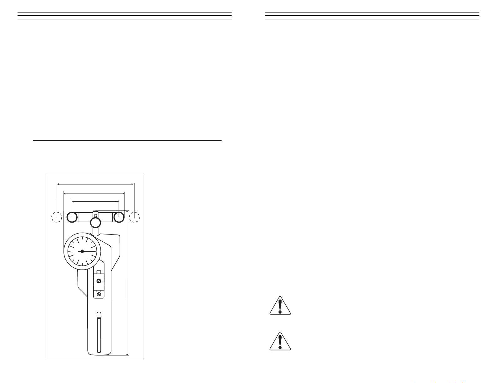
6.1 Dimensions
3.94 in. (100 mm)
4000 g range only
3.54 in. (90 mm)
2.95 in. (75 mm)
8.46 in. (215 mm)
WAR NING
WAR NING
Page 2
2
1.0 INTRODUCTION
DX2-EDM Tension Meters are hand-held, mechanical instruments which
accurately measure the running as well as static tensions at the wire used
in wire EDM machines.
The DX2-EDM employs the 3-roller principle for tension measurement where
the outer two reference guide rollers remain fixed during measurement to establish a
wrap angle over the middle sensing roller. The middle roller, acting against an internal
calibrating spring, is displaced relative to the line tension. This displacement is converted to rotary motion to turn a pointer on a scale to give a reading in grams tension.
1.1 Complete Kit
(included in shipment)
• Tension meter
• Special finger support
• Operating instructions
• Carrying case
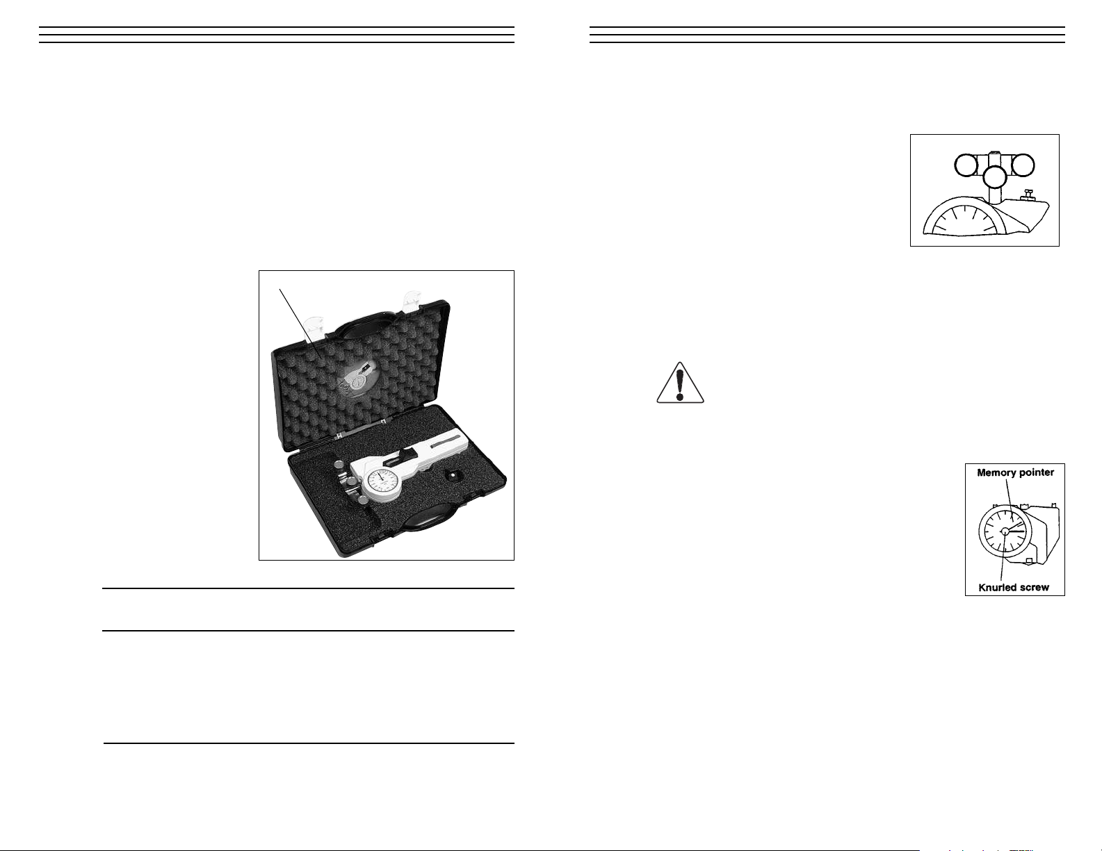
1.2 Unpacking
Unpack the tension meter
and inspect it for any
shipping damage. Notices
of defect must be filed
within 10 days of receipt
of the tension meter.
1.3 Model Ranges
Tension Roller Calibration
Ranges (cN) Distance (c:c) mm Material
050 - 2000
075 PA: 0.30 mmØ
150 - 2200
075 PA: 0.30 mmØ
100 - 3000 075 PA: 0.30 mmØ
200 - 4000 100 PA: 0.40 mmØ
Operating Instructions behind foam pad.
7
5.0 OPTIONS
5.1 Air Dashpot Damping
DX2-EDM Tension Meters incorporate a
moderate amount of movement damping to
smooth out some high frequency tension
fluctuation. However, where process fluctuations
result in rapid pointer swings which make it
difficult or near impossible to read the scale,
an optionally-available Air Dashpot Damping
mechanism can be provided to slow down the
pointer swings to permit a reading. In setting up the mechanism, it is best to set
the damping rate just to the point where a readable pointer results with minimal
pointer swings. The amount of damping is set by turning the small slotted screw
or hex-head screw of the damping assembly located near the guide-roller mounting bracket. The Air Dashpot must be installed at time of original manufacture.
It cannot be added later.
5.2 Memory Pointer
The optional Memory Pointer assembly retains the highest
reading obtained during a measuring period. Before using
the instrument, rotate the knurled pointer knob clockwise
until the “memory” pointer tab contacts the measuring
pointer at zero. During operation and after instrument
removal, the trailing “memory” pointer will hold the
maximum reading until reset with the pointer knob.
Do not set the damping rate too high as this will
damage the instrument.
CAUTION
Page 3

3
2.0 OVERVIEW
2.1 Operating Elements
2.2 Mounting Special Finger Support
Whenever useful and necessary, the tension meter is supplied with a special
finger support. We recommend mounting the finger support when measuring
high tension to reduce the necessary effort to move the outer rollers with the
Thumbpiece on the front of the tension meter and facilitate acquisition of the
wire to be measured. Place the special finger support in the recess located on the
rear side of the tension meter and fasten it with the finger support screw.
6
4.1 Frequency Of Calibration Verification
Frequency of calibration accuracy verification depends on many factors. These
include frequency and extent of tension overloads, operating speeds, length of
operating times, environment, care in handling, etc. Such determination is best
made by the user’s Quality Assurance Department based on the user's experience.
However, a quick calibration check near the anticipated process tension levels
should be done to confirm the integrity of the instrument, as follows:
1. At the beginning of each work session.
2. Every time a unit is dropped.
3. Whenever process readings seem to be out of tolerance for no apparent
reason.
The quick check can be made with a simple load stand, as shown section 4.2,
using a sample of the process material and weights that are close to the tensions
encountered in the process. Be sure to move the tension meter up and down
slowly to simulate the motion of the running process material. This will check
the condition of the guide roller ball bearings and remove any inertia effect of
the movement. Readings that change with this motion reversal may indicate the
possibility of a guide roller ball bearing problem.
In the case of wire, which might be slightly deformed by the action of the
3- roller system during static measurement, always move to a fresh portion
of the wire each time a measurement is made. (In production, the instrument
always “sees” a fresh portion.)
4.2 NIST Calibration
While all DX2-EDM instruments are furnished with a Calibration Certificate
which certifies that they have been calibrated in accordance with factory
procedures and were found to meet all published accuracy specifications,
such calibrations do not fulfill ISO-9000 requirements since no record of
measured values are kept or are submitted. Where ISO-9000 requirements
are to be met, NIST calibration is optionally available but must be specified
at time of order placement or after repair.
Thumb piece
Process
material
Guide
rollers
Scale
Measuring
roller
Thumb piece
Finger support screw
al finger support
S
Page 4

4
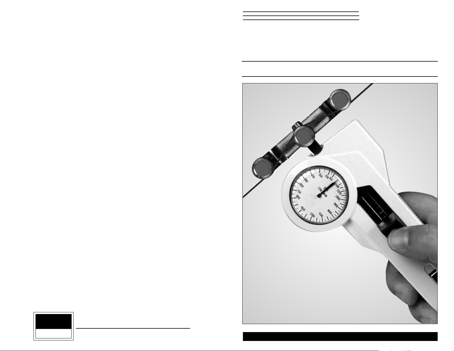
1. Prior to engaging the material under test, part the 3-roller system by pushing and
holding the Thumbpiece forward—see arrow above.
2. Keeping the outer rollers extended, bring the instrument behind or under the
wire and move it so that the process material is in contact with V-groove of the
bottom sensing roller.
3. Slowly release pressure on the Thumbpiece until the outer rollers return to their
original position. This will automatically direct the material into the guide roller
grooves.
4. The scale pointer will show line tension directly in grams or kilograms.
Removal
1. To remove the instrument from the process material, push the Thumbpiece
forward again to open the 3-roller system. With the outer rollers extended,
move the instrument away from the material.
2. Remove the instrument and SLOWLY release pressure on the Thumbpiece,
allowing the outer rollers to return to their original position.
Do not let the Thumbpiece snap back as this
may affect calibration and also damage the
instrument.
3.0 TAKING A MEASUREMENT
5
4.0 VERIFYING CALIBRATION
1. Suspend a known weight that corresponds to the tension to be measured
(pay attention to the correct unit of measure) from the process material,
vertically, see figure above.
NOTE: Always use a fresh portion of the material to be measured.
2. Push the thumbpiece as far as it will go in the direction indicated by the
arrow and thread the material to be measured between the guide rollers and
the measuring roller. Refer to Section 3.0.
3. Slowly release pressure on the thumb piece until the outer rollers return to
their original position.
4. Before the final check, move the instrument slowly up and down to
compensate any friction caused by the instrument and thus ensure
repeatability.
5. The tension value should be equal to the value of the suspended weight.
If this procedure shows a deviation beyond the allowable tolerance and a
reliable operation is no longer allowed, the instrument has to be recalibrated
or repaired. For recalibration, return the tension meter to the factory.
Guide rollers
Process material
Guide rollers
Measuring
roller
Thumb piece
CAUTION
KNOWN
WEIGHT
Page 5

9
7.0 WARRANTY
ELECTROMATIC Equipment Co., Inc. (ELECTROMATIC) warrants to the
original purchaser that this product is of merchantable quality and confirms
in kind and quality with the descriptions and specifications thereof. Product
failure or malfunction arising out of any defect in workmanship or material in the
product existing at the time of delivery thereof which manifests itself within one
year from the sale of such product, shall be remedied by repair or replacement of
such product, at ELECTROMATIC’s option, except where unauthorized repair,
disassembly, tampering, abuse or misapplication has taken place, as determined by
ELECTROMATIC. All returns for warranty or non-warranty repairs and/or replacement must be authorized by ELECTROMATIC, in advance, with all repacking and
shipping expenses to the address below to be borne by the purchaser.
THE FOREGOING WARRANTY IS IN LIEU OF ALL OTHER WARRANTIES,
EXPRESSED OR IMPLIED, INCLUDING BUT NOT LIMITED TO, THE
WARRANTY OF MERCHANTABILITY AND FITNESS FOR ANY PARTICULAR
PURPOSE OR APPLICATION. ELECTROMATIC SHALL NOT BE RESPONSIBLE
NOR LIABLE FOR ANY CONSEQUENTIAL DAMAGE, OF ANY KIND OR
NATURE, RESULTING FROM THE USE OF SUPPLIED EQUIPMENT, WHETHER
SUCH DAMAGE OCCURS OR IS DISCOVERED BEFORE, UPON OR AFTER
REPLACEMENT OR REPAIR, AND WHETHER OR NOT SUCH DAMAGE IS
CAUSED BY MANUFACTURER’S OR SUPPLIER’S NEGLIGENCE WITHIN
ONE YEAR FROM INVOICE DATE.
Some State jurisdictions or States do not allow the exclusion or limitation of incidental
or consequential damages, so the above limitation may not apply to you. The duration
of any implied warranty, including, without limitation, fitness for any particular
purpose and merchantability with respect to this product, is limited to the duration of
the foregoing warranty. Some states do not allow limitations on how long an implied
warranty lasts but, not withstanding, this warranty, in the absence of such limitations,
shall extend for one year from the date of invoice.
ELECTROMATIC Equipment Co., Inc.
600 Oakland Ave. Cedarhurst, NY 11516—USA
Tel: 1-800-645-4330/ Tel: 516-295-4300/ Fax: 516-295-4399
Every precaution has been taken in the preparation of this manual. Electromatic Equipment Co., Inc., assumes
no responsibility for errors or omissions. Neither is any liability assumed for damages resulting from the use of
information contained herein. Any brand or product names mentioned herein are used for identification purposes only, and are trademarks or registered trademarks of their respective holders.
Page 6
HAND-HELD TENSION METER
DX2-EDM
Operating Instructions
CHECK•LINE
®
BY ELECTROMATIC
ELECTROMATIC
E Q U I P M E N T C O., I N C.
600 Oakland Ave., Cedarhurst, NY 11516–U.S.A.
TEL: 516-295-4300 • FAX: 516-295-43 99
CHECK•LINE
®
INSTRUMENTS
 Loading...