

Page 1
ELECTROMATIC
E Q U I P M E N T C O., I N C.
600 Oakland Ave., Cedarhurst, NY 11516–U.S.A.
TEL: 516-295-4300 • FAX: 516-295-4399
CHECK•LINE
®
INSTRUMENTS
CHECK•LINE
®
BY ELECTROMATIC
DXN
Operating Instructions
Page 2

12
1
CONTENTS
. . . . . . . . . . . . . . . . . . . . . . . . . . . . . . . . . . . . . . . . . .Page
1.0 Overview & Operating Principle . . . . . . . . . . . . . . . 2
2.0 Operating Elements . . . . . . . . . . . . . . . . . . . . . . . . . 3
3.0 Thickness Compensation . . . . . . . . . . . . . . . . . . . . . 4
4.0 Quick Start Instructions . . . . . . . . . . . . . . . . . . . . . 5
5.0 Calibration Notes . . . . . . . . . . . . . . . . . . . . . . . . . . 6
5.1 Calibration with “Standard” Filaments
5.2 Special Calibration
5.3 NIST Calibration
5.4 Calibration Verification Schedule
6.0 Options . . . . . . . . . . . . . . . . . . . . . . . . . . . . . . . . . . . 10
6.1 High-Speed Guide Rollers
6.2 Lever Assembly
6.3 Air Dashpot Damping
7.0 Model Data & Specifications . . . . . . . . . . . . . . . . . . 12
7.0 DXN MODEL DATA & SPECIFICATIONS
Accuracy* ± 1% of full scale or
± 1 graduation mark
on scale
Diameter of Scale 54 mm
Maximum Speed
(standard) 2000 m/ min
(optional) 3500 m/ min (K)
(optional) 5000 m/ min (HS)
Outer roller distance, c:c
DXN-30 to DXN-1000 EX 38 mm
DXN-200 to DXN-10K 100 mm
DXN-2K 150 or 200 mm
DXN-30K to DXN-50K 250 mm
Roller material
(standard) Hard-coated aluminum
(optional) Hardened steel (ST)
Ceramic (CE)
Phenolic (PH)
Housing material Die-cast aluminum
Dimensions 260 x 72 x 44 mm
(10.2 x 2.8 x 1.7 in.)
Weight 700 g (1.5 lbs.), approx.
* Using factory standard materials and procedures. Special calibration using
customer sample is available.
Specifications subject to change without notice.
OI803N
Page 3
2
11
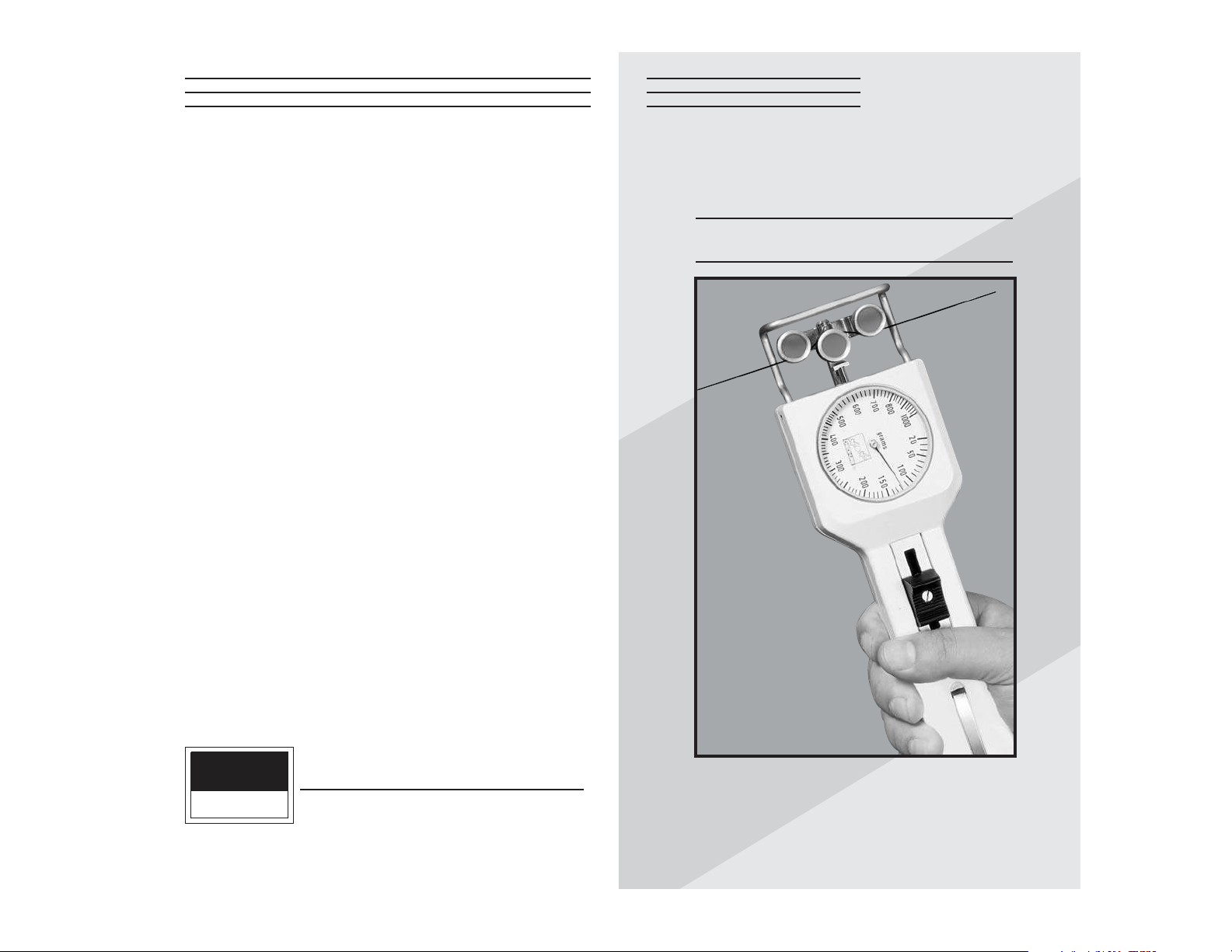
1.0 OVERVIEW & OPERATING PRINCIPLE
DXN Tension Meters are hand-held, mechanical
instruments which accurately measure the running as
well as static tensions of a wide variety of process
materials including yarns, fibers, wires, optical fibers,
tapes, etc. They employ the 3-roller principle for
tension measurement where the outer two reference
guide rollers remain fixed during measurement to
establish a wrap angle over the middle sensing roller.
The middle roller, acting against an internal
calibrating spring, is displaced relative to the running
line tension. This displacement is converted to a rotary
motion to turn a pointer on a scale to give a reading in
grams tension.
6.3 Air Dashpot Damping
DXN Tension Meters incorporate a moderate amount
of movement damping to smooth out some high frequency tension fluctuation. However, where process
fluctuations result in rapid pointer swings which make
it difficult or near impossible to read the scale, an
optionally-available Air Dashpot Damping mechanism
can be provided to
slow down the pointer
swings to permit a
reading. In setting up
the mechanism, it is
best to set the damping rate just to
the point where a
readable pointer
results with minimal
pointer swings. The amount of damping is set by turning the small slotted screw or hex-head screw of the
damping assembly located near the guide-roller mounting bracket. The Air Dashpot must be installed at time
of original manufacture. It cannot be added later.
CAUTION: Do not set damping rate too high as
this will damage the movement.
Adjustment Screw
Page 4

10 3
2.0 OPERATING ELEMENTS6.0 OPTIONS
6.1 High-Speed Guide Rollers
DXN guide roller assemblies are rated 2000
meters/min., maximum. The following high-speed
roller assemblies are optionally available:
“K” Roller Assembly : 3,500 meters/min., maximum
“HS” Assembly : 5,000 meters/min., maximum
All high speed roller assemblies must be initially
installed by the factory or an authorized service
facility.
6.2 Lever Assembly
On high-range instruments, the return spring force
must be strong enough to bring the outer rollers back
to their original position during measurement. The
average person will find it difficult to operate the
mechanism just with thumb pressure on the Thumb
Piece alone. (This is especially true with models rated
20 Kg and higher.) Adding the Lever Assembly shown
here will greatly reduce the effort required to open and
close the 3-roller system. The Lever Assembly must
be installed by the factory or an authorized service
facility.
Roller Guides
Measuring Roller
Scale
Thumbpiece
Sample Holding Clip
Measured Material
Page 5

4
9
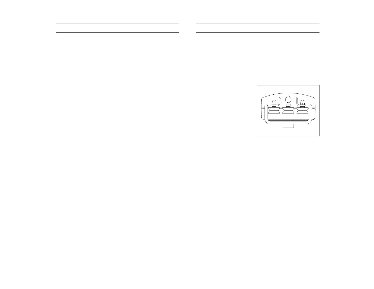
3.0 THICKNESS COMPENSATION
The 3-roller system for
tension measurement relies
on the displacement of the
middle roller to give an
indication of line tension.
As the material diameter
or thickness changes, there
will be a change in tension
reading, even though line
tension has not changed. To
offset this effect, high-range
instruments (1000 grams and higher) are usually furnished with a Thickness Compensator, as shown here.
To determine whether the Compensator needs to be
used for a specific application, take readings with and
without the process sample in the Compensator using
a hanging weight approximately equal to the process
operating tension.
To set up the Thickness Compensator, proceed as
follows:
1. With the Thumb Piece pushed forward and held,
pass a sample of the process material through the
opening at the instrument end, as pictured here,
making sure it lies between the two visible
disc-like anvil surfaces.
2. Allow the Thumb Piece to SLOWLY return to its
original position.
CAUTION: Do not let the Thumb Piece snap
back as this may affect calibration and also
damage the instrument.
3. Secure the process sample ends under the spring
clip provided or with some tape. The instrument
is now ready to use
5.4 Calibration Verification Schedule
Frequency of calibration accuracy verification depends
on many factors. These include frequency and extent
of tension overloads, operating speeds, length of operating times, environment, care in handling, etc. Such
determination is best made by the user’s Quality
Assurance Department based on the user's experience.
However, a quick calibration check near the anticipated process tension levels should be done to confirm the
integrity of the instrument, as follows:
1. At the beginning of each work session
2. Every time a unit is dropped
3. Whenever process readings seem to be out of
tolerance for no apparent reason
The quick check can be made with a simple load stand,
as shown in 5.0, using a sample of the process material
and weights that are close to the tensions encountered
in the process. Be sure to move the tension meter up
and down slowly to simulate the motion of the running
process material. This will check the condition of the
guide roller ball bearings and remove any inertia effect
of the movement. Readings that change with this
motion reversal may indicate the possibility of a guide
roller ball bearing problem.
In the case of wire, which might be slightly deformed
by the action of the 3-roller system during static
measurement, always move to a fresh portion of the
wire each time a measurement is made. (In production,
the instrument always “sees” a fresh portion.)
Page 6

5
4.0 QUICK START INSTRUCTIONS
NOTE: If tension meter is equipped with a Thickness
Compensator, first set up Compensator as indicated in
3.0.
1. Prior to engaging the material under test, part the
3-roller system by pushing and holding the Thumb
Piece forward.
2. Keeping the outer rollers extended, bring the
instrument behind or under the filament and move
it so that the Filament Guide bars contact the
process material.
3. Slowly release pressure on the Thumb Piece until
the outer rollers return to their original position.
This will automatically direct the material into the
guide roller grooves.
4. The scale pointer will show line tension directly in
grams or kilograms.
5. To remove the instrument from the process
material, push the Thumb Piece forward again to
open the 3-roller system. With the outer rollers
extended, move the instrument away from the
material.
6. Remove the instrument and SLOWLY release
pressure on the Thumb Piece, allowing the outer
rollers to return to their original position.
CAUTION: Do not let the Thumb Piece snap
back as this may affect calibration and also
damage the instrument.
8
5.2 Special Calibration
Special Calibration is optionally available for a specific
material type and size so long as the material fits the
mechanical limits and range of the instrument. The
customer must supply a 10-ft sample (3 meters) of the
material. Such calibration can be performed with or
without using the Thickness Compensator if one has
been provided with the instrument. If not specified,
the calibration facility will use its best judgment.
Note: Special calibration is available for a single
sample only.
5.3 NIST Calibration
While all DXN instruments are furnished with a
Calibration Certificate which certifies that they have
been calibrated in accordance with factory procedures
and were found to meet all published accuracy specifications, such calibrations do not fulfill ISO-9000
requirements since no record of measured values are
kept or are submitted. Where ISO-9000 requirements
are to be met, NIST calibration is optionally available
but must be specified at time of order placement or
after repair.
Page 7

6
7
5.0 CALIBRATION NOTES
The calibration process
involves hanging laboratory
weights from a fixed point,
engaging the vertical line
material which holds the
weights with the tension
meter 3-roller system,
marking a blank dial face
where the scale pointer
comes to rest for each weight used, dividing the spaces
between load “reading” marks and finish marking and
numbering to show calibration marks and “readings”
on the dial face.
The procedure requires specialized skills and the
following material:
1. A load stand to simulate the setup shown here.
2. A set of precision laboratory weights to cover the
tension range of the instrument.
3. Factory “standard” nylon monofilaments as shown
in the Table on page 7.
4. A Special Calibration Fixture and metric wrench.
A full, detailed calibration procedure is available upon
request.
5.1 Calibration with Factory Standard Filaments
All DXN Tension Meters are calibrated with laboratory
weights suspended from factory Standard nylon
monofilament sizes, as noted in the table below. Any
difference in process material size and rigidity from
the Standard materials may result in some error. For
over 95% of applications, the error is not significant
and can be ignored since readings are generally treated as production setup values or are used for
comparative purposes. In those cases where highest
accuracy is required, a correction chart showing
Readings vs. Actual Load should be made up by the
user or “Special” calibration should be specified when
an order is placed.
Standard Calibration Monofilament Sizes
Mono-
Range filament
Model (Grams) Dia. (mm)
DXN-50 5-50 0.12
DXN-120 20-120 0.12
DXN-200 20-200 0.12
DXN-400 20-400 0.20
DXN-1000 50-1000 0.30
DXN-2000 200-2000 0.50
DXN-5000 400-5000 0.80
DXN-10K 2-10 Kg 1.00
DXN-20K-L 5-20 Kg 1.50
DXN-30K-L 5-30 Kg 1.50
DXN-50K-L 5-50 Kg 1.50 (steel rope)
 Loading...