

Page 1

9.0 Warranty
Contents
ELECTROMATIC Equipment Co., Inc. (ELECTROMATIC) warrants to the
original purchaser that this product is of merchantable quality and conrms in
kind and quality with the descriptions and specications thereof. Product failure
or malfunction arising out of any defect in workmanship or material in the product
existing at the time of delivery thereof which manifests itself within one year
from the sale of such product, shall be remedied by repair or replacement of
such product, at ELECTROMATIC’s option, except where unauthorized repair,
disassembly, tampering, abuse or misapplication has taken place, as determined
by ELECTROMATIC. All returns for warranty or non-warranty repairs and/
or replacement must be authorized by ELECTROMATIC, in advance, with all
repacking and shipping expenses to the address below to be borne by the purchaser.
THE FOREGOING WARRANTY IS IN LIEU OF ALL OTHER WARRANTIES,
EXPRESSED OR IMPLIED, INCLUDING BUT NOT LIMITED TO, THE
WARRANTY OF MERCHANTABILITY AND FITNESS FOR ANY
PARTICULAR PURPOSE OR APPLICATION. ELECTROMATIC SHALL NOT
BE RESPONSIBLE NOR LIABLE FOR ANY CONSEQUENTIAL DAMAGE,
OF ANY KIND OR NATURE, RESULTING FROM THE USE OF SUPPLIED
EQUIPMENT, WHETHER SUCH DAMAGE OCCURS OR IS DISCOVERED
BEFORE, UPON OR AFTER REPLACEMENT OR REPAIR, AND WHETHER
OR NOT SUCH DAMAGE IS CAUSED BY MANUFACTURER’S OR
SUPPLIER’S NEGLIGENCE WITHIN ONE YEAR FROM INVOICE DATE.
Some State jurisdictions or States do not allow the exclusion or limitation of
incidental or consequential damages, so the above limitation may not apply to you.
The duration of any implied warranty, including, without limitation, tness for any
particular purpose and merchantability with respect to this product, is limited to the
duration of the foregoing warranty. Some states do not allow limitations on how
long an implied warranty lasts but, not withstanding, this warranty, in the absence
of such limitations, shall extend for one year from the date of invoice.
Page
1.0 Overview & Operating Principle .................................................................. 2
2.0 Operating Elements ...................................................................................... 3
3.0 Thickness Compensation .............................................................................. 4
4.0 Quick Start Instructions ................................................................................ 5
5.0 Calibration Notes ......................................................................................... 6
5.1 Calibration with “Standard” Filaments
5.2 Special Calibration
5.3 NIST Calibration
5.4 Calibration Verication Schedule
6.0 Options ......................................................................................................... 8
6.1 High-Speed Guide Rollers
6.2 Lever Assembly
6.3 Air Dashpot Damping
6.4 Memory Pointer
7.0 Model Data & Specications ........................................................................ 10
8.0 DX2 Special-Purpose Models ....................................................................... 11
9.0 Warranty........................................................................................................ 12
ELECTROMATIC Equipment Co., Inc.
600 Oakland Ave. Cedarhurst, NY 11516—USA
Tel: 1-800-645-4330/ Tel: 516-295-4300/ Fax: 516-295-4399
Every precaution has been taken in the preparation of this manual. Electromatic Equipment Co., Inc.,
assumes no responsibility for errors or omissions. Neither is any liability assumed for damages resulting
from the use of information contained herein. Any brand or product names mentioned herein are used for
identication purposes only, and are trademarks or registered trademarks of their respective holders.
12
1
Page 2
1.0 Overview & Operating Principle
8.0 DX2 Special-Purpose Models
DX2 and Tension Meters are hand-held, mechanical instruments which accurately
measure the running as well as static tensions of a wide variety of process materials
including yarns, bers, wires, optical bers, tapes, etc. They employ the 3-roller
principle for tension measurement where the outer two reference guide rollers
remain xed during measurement to establish a wrap angle over the middle sensing
roller. The middle roller, acting against an internal calibrating spring, is displaced
relative to the running line tension. This displacement is converted to a rotary
motion to turn a pointer on a scale to give a reading in grams tension.
NOTE: While illustrations show the Type DX2 Tension Meter, all references
apply to the Special Purpose Tension Meters as well.
NOTE: DX2 Special Purpose Types, including FX2, TX2, DX2F, RX2/BX2 and
KXB, are shown in the Appendix at the end of these instructions. They
all use the3-roller principle for tension measurement except that head
congurations and roller assemblies are different, having been designed
for special applications, as noted in the Appendix.
Essentially, all DX2 Special Purpose
models operate in a manner similar
to the standard Type DX2. In addition,
however, they offer special rollers an
head congurations for specic
applications.
OPTIC FIBERS — FX2
LIMITED ACCESS —DX2FTAPES —TX2
WEBS & TAPES — RX2/BX2WARP — KXB
2
11
Page 3
7.0 DX2 Model Data & Specifications
Accuracy* ± 1% of full scale or ± 1 graduation mark
on scale
Diameter of Scale 41 mm
Maximum Speed
(standard) 2000 m/min
(optional) 3500 m/min
(optional) 5000 m/min
Outer roller distance, c:c
DX2-5 to DX2-EX 38 mm
DX2-200 to DX2-1K 100 mm
DX2-2K 150 or 200 mm
Roller material
(standard) Hard-coated aluminum
(optional) Hardened steel (ST)
Chromed steel (W)
Ceramic (CE)
Plastic (PL)
Temperature limits 45–115 °F (8–45 °C)
Humidity, maximum 85%
Housing material Die-cast aluminum
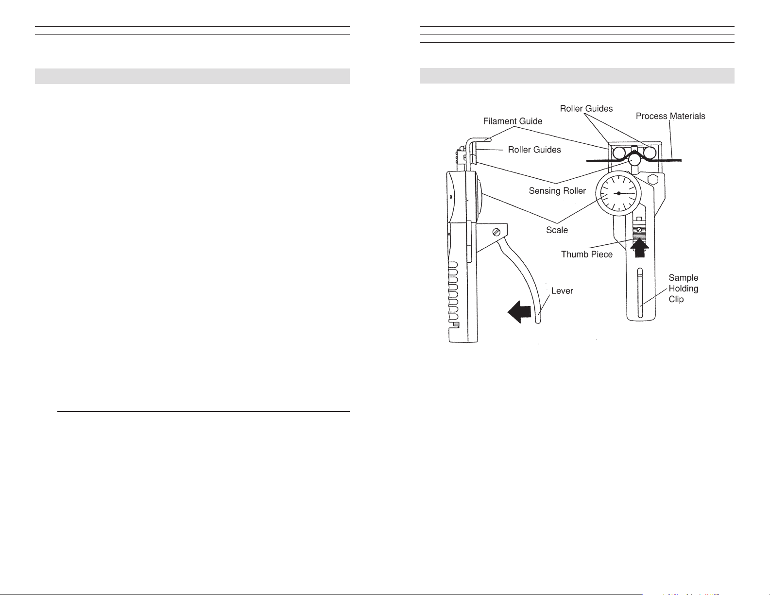
2.0 Operating Elements
Dimensions 8.6 x 3.5 x 1.7 in. (225 x 90 x 44 mm)
Weight
(up to DX2-1K) 1.1 lbs, (500 g) approx.
(DX2-2K) 2.0 lbs, (900 g) approx.
* Using factory standard materials and procedures. Special calibration using
customer sample is available.
Specications subject to change without notice.
10
3
Page 4

3.0 Thickness Compensation
The 3-roller system for tension measurement
relies on the displacement of the middle roller to
give an indication of line tension. As the material
diameter or thickness changes, there will be
a change in tension reading, even though line
tension has not changed. To offset this effect,
high-range instruments (1000 grams and
higher) are usually furnished with a Thickness
Compensator, as shown here. To determine
whether the Compensator needs to be used for
a specic application, take readings with and
without the process sample in the Compensator
using a hanging weight approximately equal to
the process operating tension.
To set up the Thickness Compensator, proceed as follows:
1. With the Thumb Piece pushed forward and held, pass a sample of the process
material through the opening at the instrument end, as pictured here,
making sure it lies between the two visible disc-like anvil surfaces.
2. Allow the Thumb Piece to SLOWLY return to its original position.
CAUTION: Do not let the Thumb Piece snap back as this may affect
calibration and also damage the instrument.
3. Secure the process sample ends under the spring clip provided or with some
tape. The instrument is now ready to use.
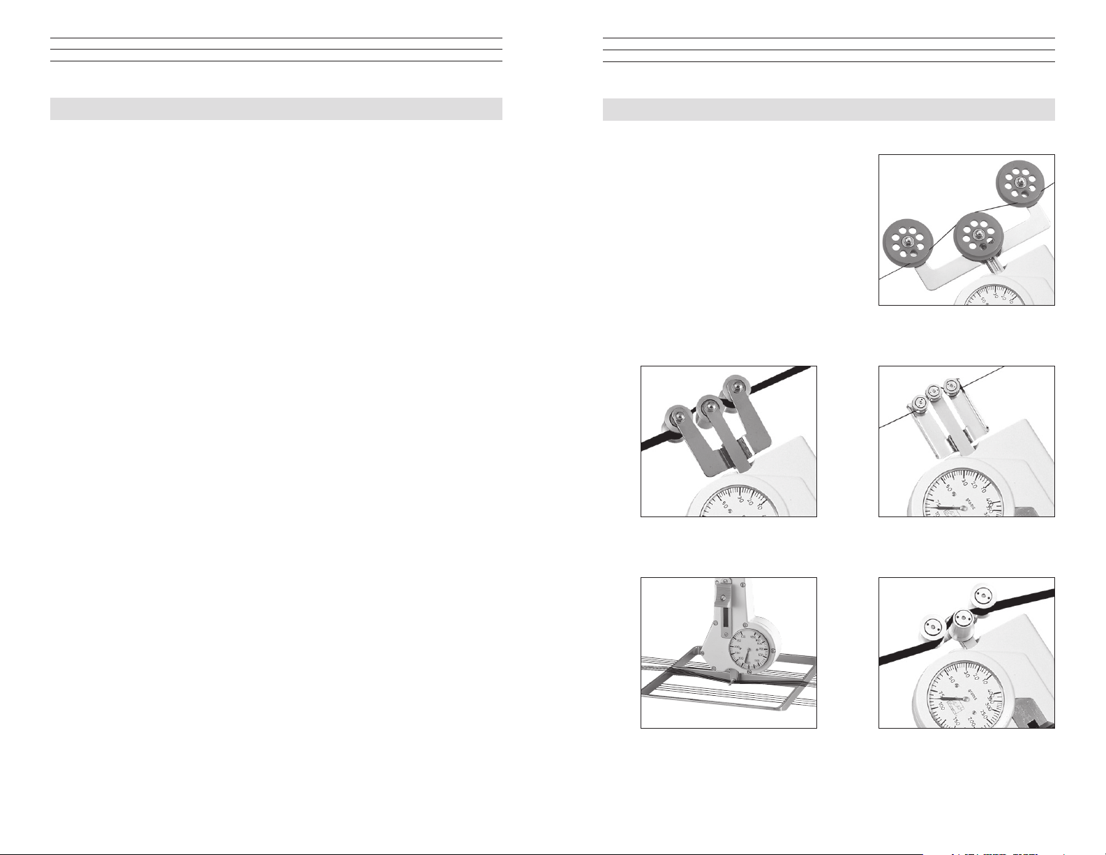
6.3 Air Dashpot Damping
DX2 Tension Meters incorporate a moderate
amount of movement damping to smooth
out some high frequency tension uctuation.
However, where process uctuations result
in rapid pointer swings which make it difcult
or near impossible to read the scale, an
optionally-available Air Dashpot Damping
mechanism can be provided to slow down the
pointer swings to permit a reading. In setting up the mechanism, it is best to set
the damping rate just to the point where a readable pointer results with minimal
pointer swings. The amount of damping is set by turning the small slotted screw or
hex-head screw of the damping assembly located near the guide-roller mounting
bracket. The Air Dashpot must be installed at time of original manufacture. It
cannot be added later.
CAUTION: Do not set damping rate too high as this will damage the
movement.
6.4 Memory Pointer
The optional Memory Pointer assembly retains
the highest reading obtained during a measuring
period. Before using the instrument, rotate
the knurled pointer knob clockwise until the
“memory” pointer tab contacts the measuring
pointer at zero. During operation and after
instrument removal, the trailing “memory”
pointer will hold the maximum reading until
reset with the pointer knob.
4
9
Page 5

6.0 Options
4.0 Quick Start Instructions
6.1 High-Speed Guide Rollers
DX2 guide roller assemblies are rated 2000 meters/min., maximum. The following
high-speed roller assemblies are optionally available:
“K” Roller Assembly: 3,000 meters/min., maximum
“U” or “DHS” Assembly 5,000 meters/min., maximum
All high speed roller assemblies must be initially installed by the factory or an
authorized service facility.
6.2 Lever Assembly
On high-range instruments, the return spring force must be strong enough to bring
the outer rollers back to their original position during measurement. The average
person will nd it difcult to operate the mechanism just with thumb pressure
on the Thumb Piece alone. (This is especially true with models rated 20 kg and
higher.) Adding the Lever Assembly shown here will greatly reduce the effort
required to open and close the 3-roller system. The Lever Assembly must
be installed by the factory or an authorized service facility.
6.2 Lever Assembly
On high-range instruments,
the return spring force must
be strong enough to bring
the outer rollers back to
their original position during
measurement. The average
person will nd it difcult to
operate the mechanism just
with thumb pressure on the
Thumb Piece alone. (This is especially true with models rated 20 kg and higher.)
Adding the Lever Assembly shown here will greatly reduce the effort required to
open and close the 3-roller system. The Lever Assembly must be installed by the
factory or an authorized service facility.
NOTE: If tension meter is equipped with a Thickness Compensator, rst set up
the Compensator as indicated in section 3.0.
1. Prior to engaging the material under test, part the 3-roller system by pushing
and holding the Thumb Piece forward.
2. Keeping the outer rollers extended, bring the instrument behind or under the
lament and move it so that the Filament Guide bars contact the
process material.
3. Slowly release pressure on the Thumb Piece until the outer rollers return
to their original position. This will automatically direct the material into the
guide roller grooves.
4. The scale pointer will show line tension directly in grams or kilograms.
5. To remove the instrument from the process material, push the Thumb Piece
forward again to open the 3-roller system. With the outer rollers extended,
move the instrument away from the material.
6. Remove the instrument and SLOWLY release pressure on the Thumb Piece,
allowing the outer rollers to return to their original position.
CAUTION: Do not let the Thumb Piece snap back as this may affect
calibration and also damage the instrument.
8
5
Page 6

5.0 Calibration Notes
The calibration process involves hanging
laboratory weights from a xed point, engaging
the vertical line material which holds the weights
with the tension meter 3-roller system, marking
a blank dial face where the scale pointer comes
to rest for each weight used, dividing the spaces
between load “reading” marks and nish marking
and numbering to show calibration marks and
“readings” on the dial face.
The procedure requires specialized skills and the following material:
1. A load stand to simulate the setup shown here.
2. A set of precision laboratory weights to cover the tension range of the
instrument.
3. Factory “standard” nylon monolaments as shown in the Table on page 7.
4. A Calibration Kit which includes an Alignment Plate and two (2) special
metric wrenches.
A full, detailed calibration procedure is available upon request.
5.1 Calibration with Factory Standard Filaments
All DX2 Tension Meters are calibrated with laboratory weights suspended from
factory Standard nylon monolament sizes, as noted in the table below. Any
difference in process material
size and rigidity from the
Standard materials may
result in some error. For
over 95% of applications,
the error is not signicant
and can be ignored since
readings are generally treated
as production setup values
or are used for comparative
purposes. In those cases where
highest accuracy is required,
a correction chart showing
Readings vs. Actual Load
should be made up by the
user or “Special” calibration
should be specied when an
order is placed.
Standard Calibration Monofilament Sizes
Model Range
(grams)
DX2-5 5–50 1000 denier or
DX2-12 10-120 0.20
DX2-20 10–200 0.20
DX2-40 10–400 0.25
DX2-SP 20–1000 0.30
DX2-EX 100–1000 0.30
DX2-200 200–2000 0.50
DX2-500 400–5000 0.80
DX2-1K 2–10 kg 1.00
DX2-2K 5–20 kg 1.20
Monofilament
Dia. (mm)
0.15 max.
5.2 Special Calibration
Special Calibration is optionally available for a specic material type and size so
long as the material ts the mechanical limits and range of the instrument. The
customer must supply a 10-ft. sample (3 meters) of the material. Such calibration
can be performed with or without using the Thickness Compensator if one has been
provided with the instrument. If not specied, the calibration facility will use its
best judgment.
NOTE: Special calibration is available for a single sample only.
5.3 NIST Calibration
While all DX2 instruments are furnished with a Calibration Certicate which
certies that they have been calibrated in accordance with factory procedures and
were found to meet all published accuracy specications, such calibrations do
not fulll ISO-9000 requirements since no record of measured values are kept or
are submitted. Where ISO-9000 requirements are to be met, NIST calibration is
optionally available but must be specied at time of order placement or after repair.
5.4 Calibration Verification Schedule
Frequency of calibration accuracy verication depends on many factors. These
include frequency and extent of tension overloads, operating speeds, length of
operating times, environment, care in handling, etc. Such determination is best
made by the user’s Quality Assurance Department based on the user’s experience.
However, a quick calibration check near the anticipated process tension levels
should be done to conrm the integrity of the instrument, as follows:
1. At the beginning of each work session
2. Every time a unit is dropped
3. Whenever process readings seem to be out of tolerance
for no apparent reason
The quick check can be made with a simple load stand, as shown in section 5.0,
using a sample of the process material and weights that are close to the tensions
encountered in the process. Be sure to move the tension meter up and down
slowly to simulate the motion of the running process material. This will check
the condition of the guide roller ball bearings and remove any inertia effect of
the movement. Readings that change with this motion reversal may indicate the
possibility of a guide roller ball bearing problem.
In the case of wire, which might be slightly deformed by the action of the 3-roller
system during static measurement, always move to a fresh portion of the wire each
time a measurement is made. (In production, the instrument always “sees” a fresh
portion.)
6
7
Page 7

CHECK•LINE
BY ELECTROMATIC
Hand-Held Tension Meter
Model DX2
®
CHECK•LINE
INSTRUMENTS
®
ELECTROMATIC
E Q U I P M E N T C O., I N C.
600 Oakland Ave., Cedarhurst, NY 11516 – USA
TEL: 516-295-4300 • FAX: 516-295-4399
Also applies to Special Purpose Models:
FX, FX2, RX/BX, RX2/BX2, DXFT, DX2FT, TX, TX2, KXB
Operating Manual
 Loading...