

Page 1
Panel Mount T achometer
ELECTROMATIC
E Q U I P M E N T C O., I N C.
600 Oakland Ave., Cedarhurst, NY 11516–U.S.A.
TEL: 516-295-4300
• FAX: 516-295-4399
CHECK•LINE
®
INSTRUMENTS
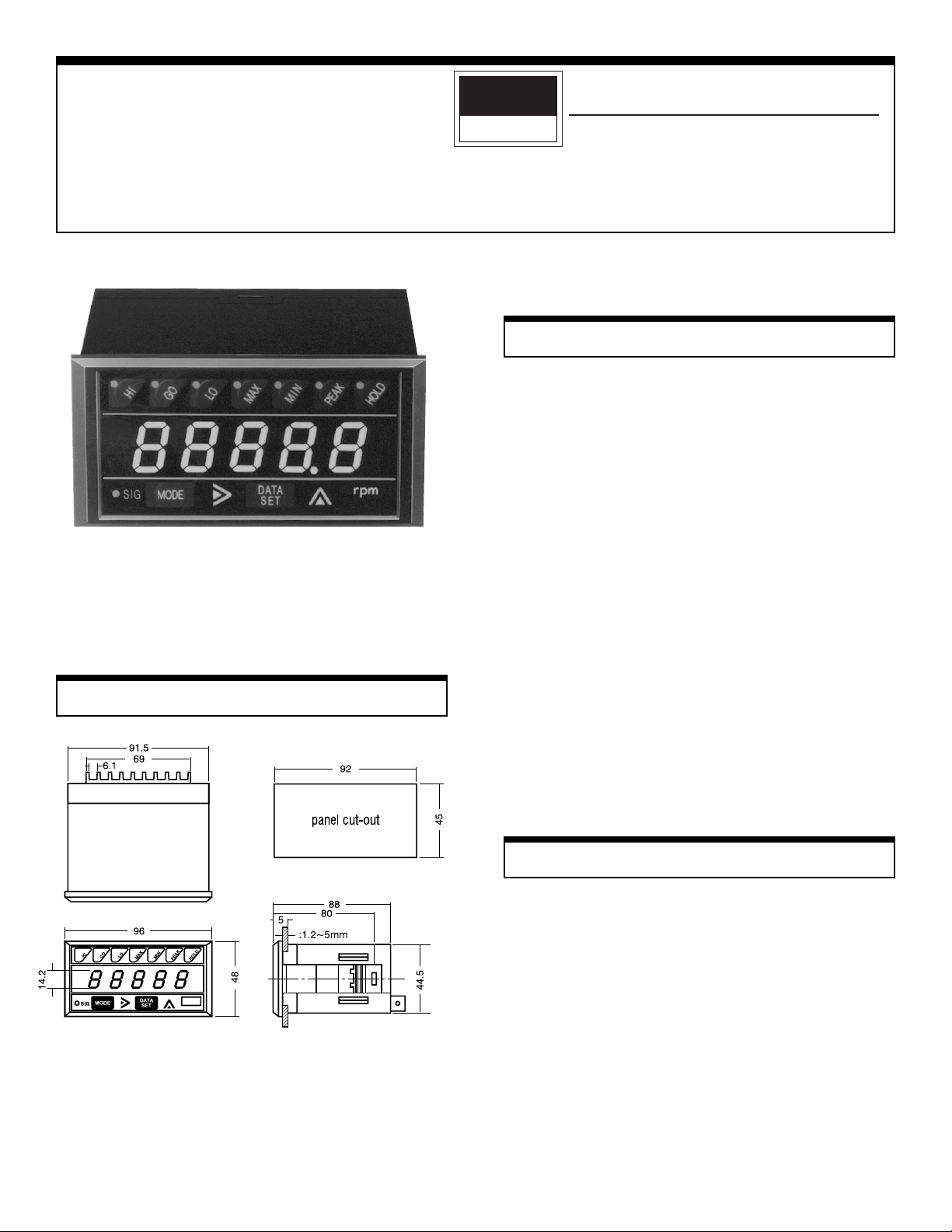
Model DT-5TG (VDC)
Dimensions (mm)
Instruction Manual
Features
One of the most advanced on the market today, this
microprocessor-based panel tachometer not only measures rotational, linear and flow rate speeds, but can also
function as an elapsed time counter and ratio meter. By
choosing the desired input/output module(s), you can
design virtually any system imaginable.
!
Mounts easily — no brackets or screws or any other
hardware needed.
!
Tolerates a wide variation of voltages.
!
Immune to electrically noisy environments.
!
Programmable parameters and functions via front
panel membrane push-button switches.
!
Accepts a variety of input and output modules
!
No need to remember mathematical formulas.
!
Highly accurate.
!
Self-testing.
Operational Precautions
!
If the unit is used in a caustic environment, we
suggest you use a NEMA 4X enclosure.
!
Keep unit free of vibration and shock.
!
When installing unit, keep power and sensor wires
separate. Tie cable shield to terminal E (earth ground).
!
After inserting wires, tighten terminal screws securely.
Page 2
Specifications Installation
Function
Function Rate Measurement
FunctionFunction
Display Range
Display Range
Display RangeDisplay Range
Measuring range
Measuring range
Measuring rangeMeasuring range
Update Time
Update Time 0.25, 0.5, 1, 2, 4, 8, 16 sec., selectable
Update TimeUpdate Time
Display
Display 5-digit LED (0.56" or 14.2 mm high)
DisplayDisplay
Time base
Time base Controlled by a 4.194304 MHz crystal
Time baseTime base
Accuracy
Accuracy ±0.008% ± 1 digit
AccuracyAccuracy
Measuring system
Measuring system CPU controlled
Measuring systemMeasuring system
Input no. of p/r
Input no. of p/r 1–9999 (programmable)
Input no. of p/rInput no. of p/r
Input signal
Input signal
Input signalInput signal
characteristics
characteristics
characteristicscharacteristics
Input signal
Input signal
Input signalInput signal
amplitude
amplitude
amplitudeamplitude
Input impedance
Input impedance
Input impedanceInput impedance
Voltage output
Voltage output 12 VDC ±5% (50 mA max) to power sensors
Voltage outputVoltage output
Applicable Sensors
Applicable Sensors
Applicable SensorsApplicable Sensors
Ambient temperature
Ambient temperature 32°–113° F (0°–45° C)
Ambient temperatureAmbient temperature
Power consumption
Power consumption 1W (5W when using optional modules)
Power consumptionPower consumption
Voltage requirements
Voltage requirements 9–35 VDC
Voltage requirementsVoltage requirements
Dimensions
Dimensions
DimensionsDimensions
Weight
Weight 0.55 lbs (250g)
WeightWeight
Rate Measurement Elapsed Time Counter
Rate MeasurementRate Measurement
0.0000–9.9999
0.000–99.999
0.00–999.99
0.0–9999.9
0–99999
10–99999 rpm (at 1p/r), 0.2–30000 rpm
(at 60p/r)
Sine wave–max frequency 10 kHz
Square wave–max frequency 30 kHz
open collector
Contact closure–max frequency 20 Hz
Sine wave (0.3–30 VP–P)
Square wave LO: 0–1.5 V, HI 4–30 V
10 k ohms for magnetic pickup, rotary pulse
generator and proximity switch only
rotary pulse generator, magnetic pickup,
proximity switch, retro-reflective
3.46"L x 1.88"H x 3.78"W (88L x 48H x 96W
mm), includes bezel, fits 1/8 DIN cutout
Elapsed Time Counter
Elapsed Time CounterElapsed Time Counter
99.99 sec.
99 min. 59 sec.
99 hours 59 min.
Mounting Unit
Our 1/8 DIN case design eliminates the need for brackets
and screws for installation. With the tachometer in a level
position, insert it into the panel cutout. Gently push the
face of the unit until the front bezel locks into place. If the
tachometer case is loose, adjust the integral bracket with
the enclosed tool.
Removing unit
From the rear of the tachometer, alternately push the unit
from the left and right. This will free it for easy removal.
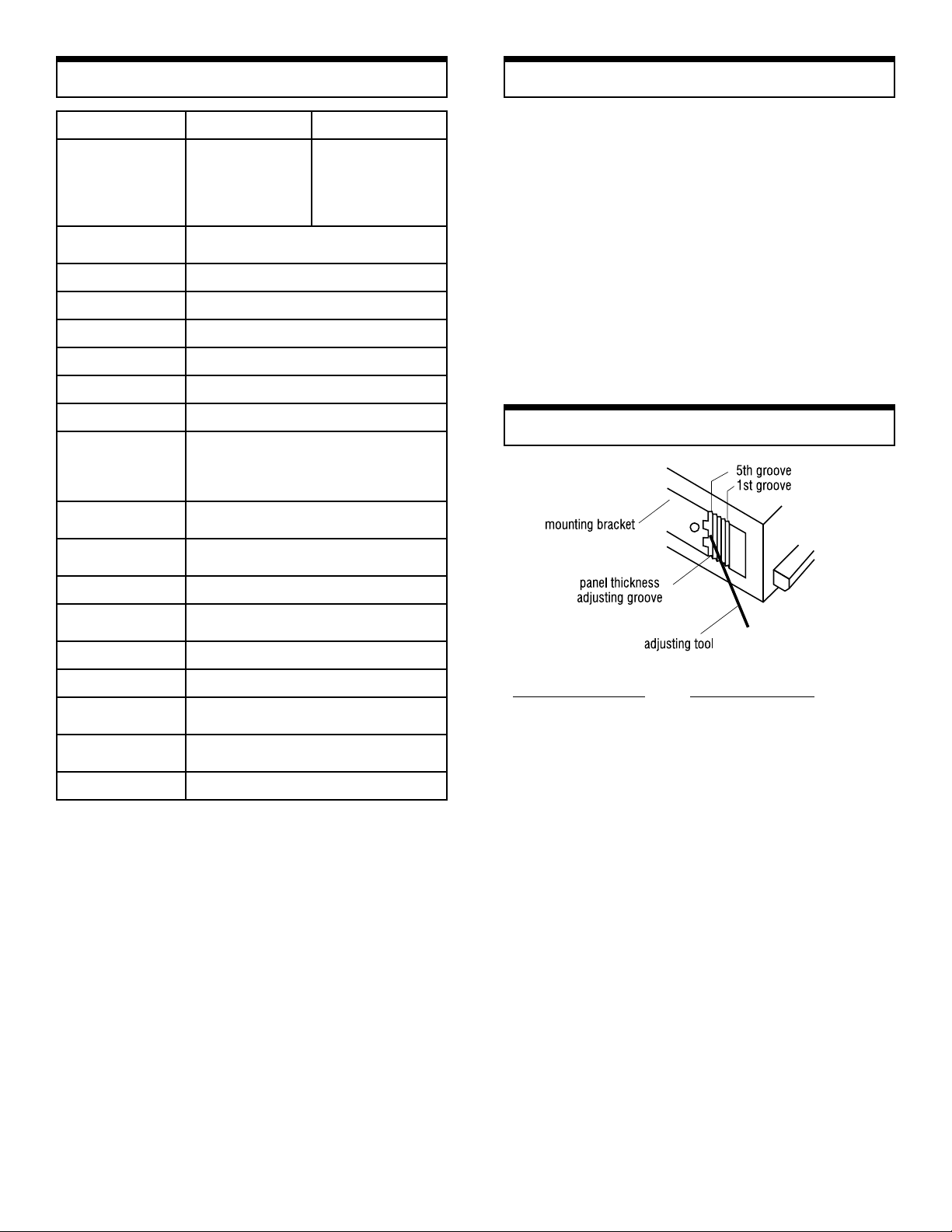
Mounting Bracket Adjustment
Panel Thickness
Thickness of Panel Adjusting Groove
1.2 – 1.6 mm 5th groove (factory setting)
1.8 – 2.5 mm 4th groove
2.8 – 3.6 mm 3rd groove
4.0 – 4.5 mm 2nd groove
5.0 mm 1st groove
2
Page 3
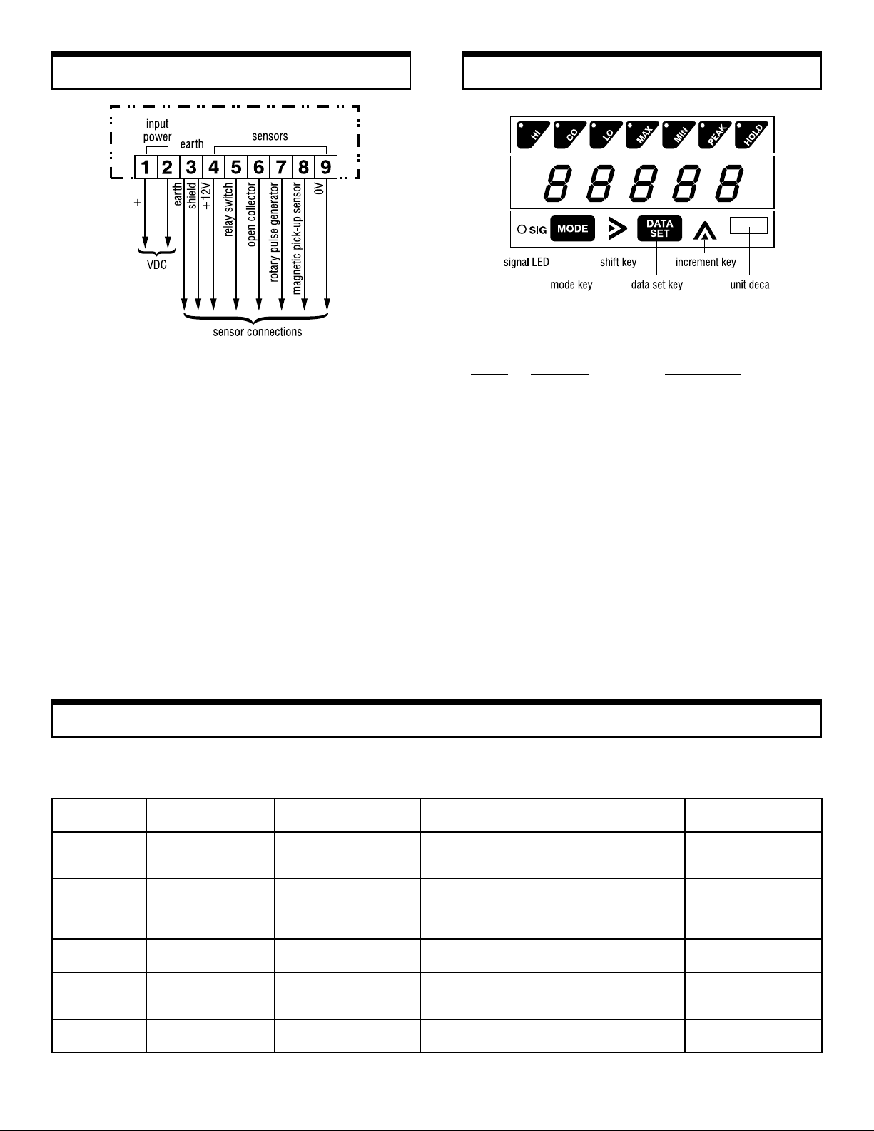
Connections
1&2 DC input terminals.
3 Earth ground. Connect all cable shielding to this
terminal.
4 12 VDC 50mA max. This sensor power supply is for
any sensor that requires external power
5 Switch closure input. To be used with a relay or
solenoid. The input frequency must be less than 20Hz.
6 For use with open collector sensors. Connect the
sensor's signal output wire. No need for an external
pull-up resistor.
7 Terminal to accept signals from rotary encoders or
pulse generators.
8 Standard input terminal for magnetic pick-ups and
proximity switches.
9 Signal ground or common.
Mode Selections
The DT-5TG has five modes of operation. Each mode
uses separate parameters for you to program:
Mode Function Application
1 Rate measurement Measures rotational
(frequency input) linear or flow rate speeds.
Factory set.
2 Elapsed time counter Times variable processes.
3 Rate measurement For tachogenerator or
voltmeter. Requires input
module DOP-VF.
4 Ratio meter Compares two signals in
either absolute or percent
ratio. Requires input
module DOP-RM.
5 Self test Diagnostically tests LED
display, panel switches
and input circuitry.
Sensors
Shimpo offers a large selection of sensors to meet you application needs. The chart below shows
the optimum sensor to use when designing your system. Please call us for more information.
ROSNESEPYTYCNEUQERFSREBMUNLANIMRETEGNARMPRROYCNEUQERF
C06B1ER
C006B1ER
C0001B1ER
21S2IB
G2JD
GES
H022SR
526SCM
NA0303
01PM
*A0703
hctiwS
erusolC
* explosion proof
esluPyratoR
rotareneG
hctiwSytimixorP
hctiwSytimixorP
raeGytimixorP
rosneS
evitcelfeRorteR
rosneS
pu-kciPcitengaM
dioneloSroyaleR,9,5zH02<
,9,7,4
,9,7,4
,9,7,4
,9,6,4
,8,4
,9,7,4
,9,7,4
,9,6,4
,3,9,8
,3,9,8
,9,8,3
mpr00050
mpr00030
mpr00810
zHK20
ZHK10
zHK80
zH0050
zH0520
NOITAREPO
ERUTAREPMET
F°221+otF°41+
F°221+otF°41+
F°221+otF°41+
F°851+otF°31F°041+otF°86-
F°851+otF°4-
F°041+otF°41+
F°021+otF°22-
F°522+otF°001-
F°122+otF°04-
F°002+otF°001-
3
Page 4

Setting ParametersSetting Modes
1.Apply any voltage between
9–35 VDC to terminals 1 and
2. When power is applied, the
display will show all zeroes. After
half a second, the display will
change to
00
0.
00
2.Press mode and data set keys for
at least 5 seconds. A zero will
flash until
11
1 appears on the
11
display.
3.Press the increment key to select
the mode you want. Mode
sequence will depend on input
module
4.Press mode key. You're now
ready to program the parameters
for the mode you have selected.
Mode 1: Rate Measurement
Parameter 1:
Pulses Per Revolution from Sensor
Here's how to change the parameter from 1 to 60 pulses
per revolution ("p/r"):
1. Set unit to mode 1.
2. Press mode key.
3. Press shift key to select the
desired digit.
4. Press increment key 6 times.
5. Press shift key.
6. Press increment key 9 times.
Parameter 1 is now set for 60 p/r.
Parameter 2: Sensing RPM
To change the parameter from 50,000 to 1,000 rpm.
The DT-5TG can easily measure any rotational, linear or
flow rate speed. Each parameter function dictates the
necessary steps when preparing a system application.
Parameters 2 and 3 can be measured with a hand-held
digital tachometer (no need for arithmetic calculations).
Parameter
Parameter Function Setting
ParameterParameter
1
2 Sensing rpm 50,000 rpm
3 Display units
4 Decimal point none 0 – 4th place
5
6 Update time 1 .25, .5, 1, 2, 4, 8, 16
7 Acceleration 0 0, 1, 2
Function Setting Factory
Function SettingFunction Setting
Pulses per
revolution
Minimum rpm
(sensor)
Factory Range
FactoryFactory
1p/r 1 – 9999
50,000 rpm
(rpm, fpm, ips)
10 rpm
Range
RangeRange
1. Press mode key
2. Press shift key
3. Press increment key five times.
4. Press shift key
5. Press increment key.
4
Page 5

Setting Parameters (cont'd)
Parameter 3: Display Units
Program this parameter to the desired display value
corresponding to the parameter 2 setting. For example,
suppose a conveyor is running at 157 fpm and 1,000 rpm
sensing speed. This parameter would then be programmed for 157.
1. Press mode key.
2. Press increment and shift keys
to change display.
To get a decimal point, increase the parameter 3 setting
by a power of 10, depending on the number of decimal
places needed. For one decimal place (in this example),
program the display for
program
1570015700
15700.
1570015700
0157001570
01570. For two places,
0157001570
Parameter 7: Acceleration
This parameter is useful when rate speeds accelerate or
stop rapidly. If the tachometer senses a large rate
change, the update time automatically switches to .25
seconds. When the tachometer senses a constant rate, the
update time is determined by parameter 6.
1. Press mode key
2. Press shift key to set parameter:
00
0 = No function
00
11
1 = Rapid stop
11
22
2 = Acceleration (input
22
frequency must be ≥7 Hz)
Parameter settings are now complete. Press data set key
to start measuring.
Parameter 4: Decimal Point
1.Press mode key (Skip to
parameter 5 if you don't want a
decimal point).
2.Press shift key to select position
of decimal point.
Parameter 5: Minimum RPM (sensor)
Set this parameter to the highest value possible.
1. Press mode key.
2. Press shift and increment keys
to change display.
Parameter 6: Update Time
1. Press mode key.
2. Press shift key to select update
time.
Field Adjustment
In the rate measurement mode, parameter 3 can be
adjusted without following the parameter sequence. For
example, suppose the initial parameter 2 and 3 settings are
50,000 rpm. But during actual measurements, the display
shows 3,800 rpm when the sensing speed is 3,500 rpm.
The DT-5TG can be quickly adjusted:
1. Press mode and increment keys simultaneously for
5 seconds.
2. Press shift and increment keys to make adjustment.
3. Press data set key — you're now ready to measure
speed.
If the display shows
eter 2 and 3 is too large. Press data set key and readjust
these parameters according to the parameter setting
procedure outlined earlier.
EE-00EE-00
EE-00, the ratio between param-
EE-00EE-00
5
Page 6

Mode 2: Elapsed Time Mode
This mode monitors the time of a continuously variable
process. Say, for example, a baker wants to know the
amount of time needed to bake cookies. By using a
stopwatch, he could measure the amount of time it takes
at a known speed of the conveyor. Or, the baker could
calculate this time by using the distance formula d=vt.
By knowing the calculation time (parameter 4) and rpm of
the sensing gear (parameter 2), the baker can continu-
ously monitor the time as the process varies.
Parameter
Parameter Function Setting
ParameterParameter
1
2 Sensing gear –rpm 200
3 Time units (=.)
4 Calculation time 02=.00
5 Update time 1 .25, .5, 1, 2, 4, 8, 16
Function Setting Factory
Function SettingFunction Setting
Sensing gear
–pulses/ revolution
Factory Range
FactoryFactory
Range
RangeRange
1 1 – 9999
(–.)=sec/sec
(=.)=min/sec
or hr/min
Parameter 3: Time Units
1. Press mode key.
2. Press shift key to select units.
Unit symbols:
=. hour/minute or minute/second
–. second/second
Parameter 4: Calculation Time
1. Press mode key.
2. Press shift and increment keys to
program time calculated.
Parameter 1:
Sensing Gear – Pulses per Revolution
This example shows how to change the parameter from 1
to 60 pulses per revolution.
1. Set the unit to mode 2.
2. Press mode key.
3. Press shift key 4 times.
4. Press increment key 6 times.
5. Press shift key.
6. Press increment key 9 times.
Parameter 2: Sensing Gear — RPM
Here's how to change the parameter from 200 to 100 rpm:
If the display shows
--=.E9--=.E9
--=.E9, an entry error has been
--=.E9--=.E9
made. Reprogram the unit using the shift and increment
keys.
Parameter 5: Update Time
1. Press mode key.
2. Press shift key to select update
times.
The parameter settings are now
complete. Press data set key to start
elapsed time counter.
1. Press mode key.
2. Press shift key 3 times.
3. Press increment key 9 times.
6
Page 7

Mode 5: Self Test
Display Switches & Functions
This mode lets you check the LED display and input
circuitry.
1.Press mode and data set keys for
five seconds.
2.Press increment key and select
mode 5.
3.Press mode key to test display
segments and decimal points.
4. Some display functions switches
can also be checked. Press these
keys to test:
MAX
MIN
PEAK
HOLD
5.Press mode key. The display will
10001000
show
1000 and signal
10001000
flash.
6.Press data set key. The display will
go back to the previous mode of
operation.
LEDLED
LED will
LEDLED
The DT-5TG has seven display functions located above
the display. All functions have an LED indicator and all
but GO have a membrane switch. Here is a brief description of each function:
HI If the display is equal to or greater than the HI
limit setting, the LED will light and a contact
will close.* To program, press HI and mode keys
for one second. Use the increment and shift
keys to set limit.
GO If the display is between the HI and LO settings,
the LED will light and a contact will close.*
LO If the display is equal to or less than the low limit
setting, the LED will light and a contact will
close.* To program, press LO and mode keys for
one second. Use increment and shift keys to set
limit.
MAX The display will hold the average maximum
measurement. To program, press MAX and
mode keys until LED lights.
MIN The display will hold the average minimum
measurement. To program, press MIN and
mode keys until LED lights.
PEAK The display will hold the absolute peak measure-
ment. To program, press mode and PEAK keys
until LED lights.
HOLD This function will hold the display indefinitely as
long as the unit is powered. To program, press
mode and HOLD keys until LED lights.
*Requires the DOP-CP Triple Relay Output Module.
Note:
! The HI, GO and LO functions are non volatile
and may be reset by programming to zero.
! The MAX, MIN, PEAK and HOLD functions
must be used separately. These functions may be
reset by pressing the data set key or by interrupt-
ing power.
Error Codes
Display Type of Error What to Do
EE-00EE-00
EE-00 Parameter setting Press data set key. Enter parameter according to setting range.
EE-00EE-00
EE-01EE-01
EE-01 Hi/Lo setting Press data set key. Enter the upper and lower limits.
EE-01EE-01
EE-02EE-02
EE-02 Internal setting Press data set key. Interrupt power at terminals 1 and 2.
EE-02EE-02
EE-03EE-03
EE-03 Memory recall Press data set key. In sequence, press HI, hold, increment and mode keys.
EE-03EE-03
EE-04EE-04
EE-04 Communication Check connections with module. Press data set key.
EE-04EE-04
EE-05EE-05
EE-05 error with
EE-05EE-05
EE-06EE-06
EE-06 module
EE-06EE-06
7
Page 8

Available Modules
ELECTROMATIC
E Q U I P M E N T C O., I N C.
600 Oakland Ave., Cedarhurst, NY 11516–U.S.A.
TEL: 516-295-4300
• FAX: 516-295-4399
CHECK•LINE
®
INSTRUMENTS
Optional modules are available from Shimpo. Choose any
of the following modules – no internal hardware modifi-
cation is required.
Module connectors:
DOP-1A For single module
DOP-2A For dual module
Modules:
DOP-VF Voltage input
DOP-RM Ratio input
DOP-SD RS232C/Mitutoyo output
DOP-CP Tripl e r el ay o ut put
DOP-BC BCD output
DOP-FV Voltage/current output
DOP-PO Parallel output
The DT-5TG is available with one, two, or three module
connectors. Each type is indicated by its suffix:
DT-5TG-0 No connector
DT-5TG-1 1 connector
DT-5TG-2 2 connectors
Multiple Modules:
In most applications, two modules may be interfaced with
the DT-5TG-2. Below are the specific combinations:
CP
CP
CP
CPCP
SD
SD
SDSD
PO
PO
POPO
BC
BC
BCBC
FV
FV
FVFV
VF
VF
VFVF
RM
RM
RMRM
CP SD
CPCP
SD PO
SDSD
! ! ! ! ! ! !
! ! ! ! ! ! !
! ! ! ! ! ! !
! ! ! ! ! ! !
! ! ! ! " " "
! ! ! ! " " "
! ! ! ! " " "
PO BC
POPO
BC FV
BCBC
FV VF
FVFV
VF RM
VFVF
RM
RMRM
!#available
#can't be combined
"
$$$$$$$$$$$$$$$$$$$$$$$$$$$$$$$$$$$$$$$$$$$$$$$$$$$$$
SHIMPO ONE-SHIMPO ONE-
SHIMPO ONE-
SHIMPO ONE-SHIMPO ONE-
LIMITED EXPRESS WARRANTY:LIMITED EXPRESS WARRANTY:
LIMITED EXPRESS WARRANTY: Shimpo Instruments warrants, to the original purchaser of new
LIMITED EXPRESS WARRANTY:LIMITED EXPRESS WARRANTY:
products only, that this product shall be free from defects in workmanship and materials under
normal use and proper maintenance for one year from the date of original purchase. This warranty
shall not be effective if the product has been subject to overload, misuse, negligence, or accident,
or if the product has been repaired or altered outside of Shimpo Instruments’s authorized control in
any respect which in Shimpo Instruments’s judgment, adversely affects its condition or operation.
DISCLAIMER OF ALL OTHER WARRANTIES:DISCLAIMER OF ALL OTHER WARRANTIES:
DISCLAIMER OF ALL OTHER WARRANTIES: The foregoing warranty constitutes the SOLE AND
DISCLAIMER OF ALL OTHER WARRANTIES:DISCLAIMER OF ALL OTHER WARRANTIES:
EXCLUSIVE WARRANTY, and Shimpo Instruments hereby disclaims all other war ranties, expressed,
statutory or implied, applicable to the product, including, but not limited to all implied warranties
of merchantability and fitness.
LIMITLIMIT
AA
TION OF REMEDTION OF REMED
LIMIT
A
TION OF REMED
LIMITLIMIT
AA
TION OF REMEDTION OF REMED
TO REPAIR OR REPLACE the defective product or part, at Shimpo Instruments’s option. Shimpo
$$$$$$$$$$$
YY
::
Y
: Under this warranty, Shimpo Instruments’s SOLE OBLIGATION SHALL BE
YY
::
$$$$$$$$$$$$$$$$$$$$$$$$$$$$$$$$$$$$$$$$$$$$$$$$$$$$$
YEAR WYEAR W
YEAR W
YEAR WYEAR W
ARRANTYARRANTY
ARRANTY
ARRANTYARRANTY
Instruments reserves the right to satisfy warranty obligation in full by reimbursing Buyer for all
payments made to Shimpo Instruments, whereupon, title shall pass to Shimpo Instruments upon
acceptance of return goods. To obtain warranty service, Purchaser must obtain Shimpo Instruments’s
authorization before returning the product, properly repackaged, freight pre-paid to Shimpo Instruments.
INDEMNIFICATION & LIMITATION OF DAMAGES:INDEMNIFICATION & LIMITATION OF DAMAGES:
INDEMNIFICATION & LIMITATION OF DAMAGES: Buyer agrees to indemnify and hold Shimpo
INDEMNIFICATION & LIMITATION OF DAMAGES:INDEMNIFICATION & LIMITATION OF DAMAGES:
Instruments harmless from and against all claims and damages imposed upon or incurred arising,
directly or indirectly, from Buyer’s failure to perform or satisfy any of the terms described herein. In
no event shall Shimpo Instruments be liable for injuries of any nature involving the product, including
incidental or consequential damages to person or property, any economic loss or loss of use.
MERGER CLAUSE:MERGER CLAUSE:
MERGER CLAUSE: Any statements made by the Seller’s representative do not constitute warranties
MERGER CLAUSE:MERGER CLAUSE:
except to the extent that they also appear in writing. This writing constitutes the entire and final
expression of the par ties’ agreement.
$$$$$$$$$$$
 Loading...