

Page 1
TORQUE MEASUREMENT
10/12
2 YEAR WARRANTY (RESTRICTIONS APPLY)
Imada, Inc. warrants its products to the original purchaser to be free from defects in
workmanship and material under normal use and proper maintenance for two years (one year
for adapters, attachments, batteries, and cables) from original purchase. This warranty only covers
defective material and labor and does not cover calibration, freight, fees and expenses and shall
not be effective if the product has been subject to overload, shock load, improper battery
charging, misuse, negligence, accident or repairs attempted by others than Imada, Inc.
During the warranty period, we will, at our option, either repair or replace defective products.
Please call our customer service department for a return authorization number and return the
defective product to us with freight prepaid.
The foregoing warranty constitutes the SOLE AND EXCLUSIVE WARRANTY, and we hereby
disclaim all other warranties, express, statutory or implied, applicable to the products and/or
software, including but not limited to all implied warranties of merchantability, fitness, noninfringement, results, accuracy, security and freedom from computer virus. In no event shall
Imada, Inc. and/or its affiliated companies be liable for any incidental, consequential or punitive
damages in connection with the use of its products and/or software.
Specifications subject to change without notice.
INSTRUCTION MANUAL
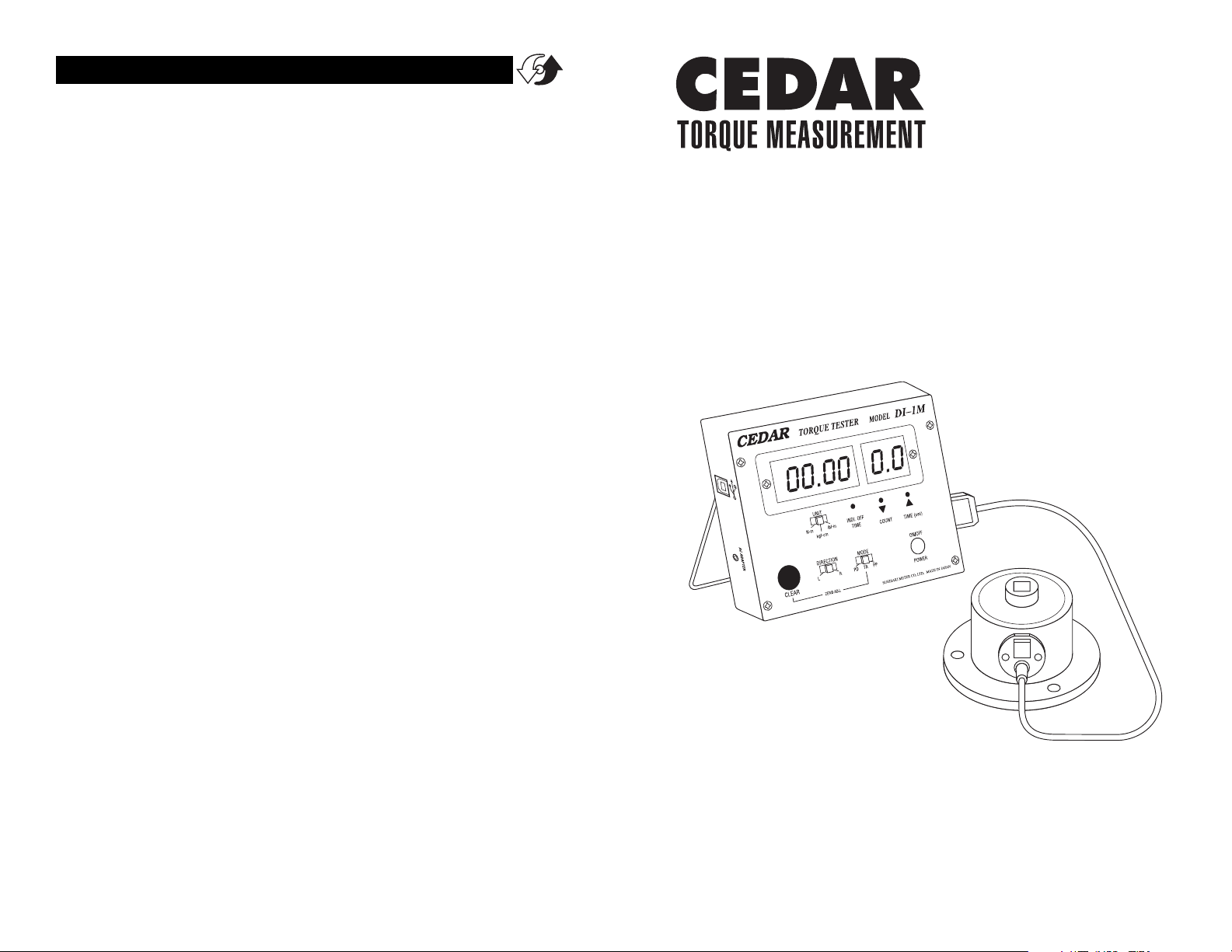
Digital Torque Tester
for impact drivers & air tools
Model: DI-1M
V-62334
Page 2
page 11page 2
TORQUE MEASUREMENTTORQUE MEASUREMENT
SPECIFICATIONS
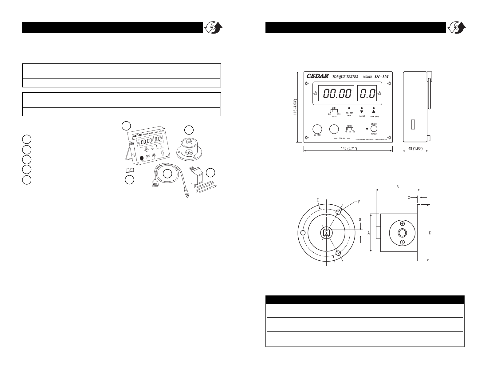
LIST OF EQUIPMENT
Torque Tester Display Unit
Torque Sensor
Cable
AC adapter/charger
Units designator
1
2
3
4
5
1
2
3
4
5
READ FIRST: SAFETY INFORMATION
For safety, and for damage avoidance, be sure to read this manual
thoroughly. The warranty is only valid when the product is used following the instructions provided within this manual.
l
Do not use tester in high temperature, high humidity, or in
damp or wet areas.
l
Recommended operating temperature is between 0-42ºC (32100ºF).
l
Do not apply torque exceeding the rated capacity, regardless of
whether the unit is On or Off.
l
When charging the battery, be sure to use the provided AC
adapter/charger exclusively.
l
When measuring torque, the unit will have a tendency to turn. In
order to avoid spinning and possible accident, it is very important to securely mount the unit to a stable work bench.
l
Do not use lacquer thinner or any solvent to clean the unit.
l
Do not disassemble or modify the unit.
Model
lbf-in kgf-cm N-m
DI-1M-50 3.0~440.0 3.0~500.0 30~5000 (
N-cm)
DI-1M-200A 30~1800 30~2000 3.0~200.0
Model
lbf-ft kgf-m N-m
DI-1M-200 3.0~145.0 0.30~20.00 3.0~200.0
DI-1M-500 3.0~362.0 0.30~50.00 3.0~500.0
DI-1M Ranges Accuracy: ±0.5% F.S. ±1 LSD
DIMENSIONS
ABCDEFG
DI-1M-50IP ∅50 63 10 ∅90 ∅76 ∅6.5 9.5
(1.97") (2.48") (.39") (3.54") (2.99") (.26") (3/8" Female Drive)
DI-1M-200IP ∅60 72 10 ∅110 ∅90 ∅9.0 12.7
(2.36") (2.83") (.39") (4.33") (3.54") (.35") (1/2" Female Drive)
DI-1M-500IP ∅80 99 15.5 ∅140 ∅116 ∅10.5 19
(3.15") (3.89") (.61") (5.51") (4.57") (.41") (3/4" Female Drive)
Page 3

page 3page 10
TORQUE MEASUREMENTTORQUE MEASUREMENT
ON/OFF Switch Press to turn on, press again to turn off (click
once, do not hold). After 10 minutes of non-use the unit shuts off.
Mode Select Switch
PD (Peak Down): To capture critical first peak value.
C (Real Time): To display torque transients.
PP (Peak): To capture peak torque achieved during a test.
CLEAR Switch To reset the display or output peak data
Zero Adjustment Pot.
LED Display Displays torque and low battery icon (LOBAT).
Torque Value
Number of Blows
Sensor Cable Receptacle
AC Charger/Adapter Receptacle If LOBAT icon appears,
8-hour battery recharge is required.
System Reset Button When battery has been depleted completely and a recharge has been executed, the system may not
yet work. In this case, press the System Reset Button.
Unit Switch To select measuring units (lbf-in, kgf-cm & N-cm)
USB port (Virtual RS-232 Output)
Blow Counter Duration Timer Use a paper clip to push the
switches, right to increase, left to decrease.
Auto Zero Reset Switch
123 4
5a
5b
6
7
8
91012
11
1
2
3
4
5a
5
5b
6
7
8
9
10
11
12
DI-1M-IP SPECIFICATIONS
DI-1M-IP50 DI-1M-IP200 DI-1M-IP500
Measuring Range 0.30 50 N-m 3.0 200 N-m 3.0 500 N-m
3.0 500 kgf-cm 30 2000 kgf-cm 30 5000 kgf-cm
3.0 430 lbf-in 30 1800 lbf-in 30 4500 lbf-in
Peak Down 0.70N-m 7.0N-m
Operating Range 7.0kgf-cm/lbf-in 70kgf-cm/lbf-in
Accuracy ±0.5 F.S.
Display 4 digit LED
Operation Both CW and CCW
Measuring Modes P-P Peak Mode displays PEAK torque value
that will not change until a higher value is measured.
T-R Real Time Mode displays TRANSIENT torque values.
P-D Output Torque Data every 1/87 seconds.
Auto Clear Automatically zero the display, 0.5 - 3.0 sec,
selectable at 0.5 sec intervals (0.0 sec for manual)
Blow Measurement 0 - 99 blows; 0.1 - 9.9 seconds
Data Output ASCII format (baud rate 19,200)
Power Supply Ni-Cad rechargeable battery 1.2Vx5cells (700mAh)
Auto Shut Off Automatic shut off after 5 minutes of non-use
Charging Time 8 hours
Working Time 8 hours continuous
Meter Weight Approx. 600g
Sensor Weight Approx. 600g Approx. 1kg Approx. 2.5kg
Meter Dimensions 146mm(W) x 115mm(D) x 48mm(H)
Accessories Carrying case, AC/DC adapter
Page 4

page 9
TORQUE MEASUREMENT
page 4
TORQUE MEASUREMENT
GENERAL OPERATION
IMPORTANT! Always make sure that the sensor is mounted securely
to a stable workbench to avoid spinning and possible accident.
1. Connect the torque sensor to the tester display unit with cable
provided. When connecting the cable to the torque sensor,
rotate the round connector to find the matching groove, then
push in until it makes positive connection (When disconnecting
the cable, hold the silver metal part of the round connector and
pull out).
2. Select measuring unit (lbf-in/lbf-ft, kgf-cm/ kgf-m, or N-cm/N-m).
If desired, affix unit designator to prevent it from being accidentally changed.
3. Select among the following
Measurement Modes (For normal testing, PP mode is recommended).
PP (Peak Mode): Capture peak torque
PEAK Torque reading will not change
until a higher value is measured (peak
data output).
C (Real Time Mode): Display torque transient (no output).
PD (Peak Down Mode): Capture first peak value and will not
change even if a higher value is subsequently measured (peak data
output).
4. Press ON/OFF, if the unit does not display zero, select TR mode
and use the Zero Adjustment Pot. to make sure the display
reads zero.
5. Select Peak Mode (PP) or Peak Down mode (PD).
6. The blow counter counts the number of pulses
for a specified time, up to 9.9 seconds. The counter
works in PP mode only. Set the time duration by
using a pointed tool like a paperclip to push the
switches , right to increase, left to decrease.
7. Insert wrench drive securely into the sensor, hold
perpendicularly (not at an angle), and turn on
the tool to measure.
8. After taking measurement, press CLEAR to
zero the display for the next test.
11
3
4
SW-1SV-USB is a highly customized
Excel spreadsheet specifically
designed for capturing and analyzing real-time data from Cedar
torque instruments with a USB
port. SW-1SV-USB provides a running log of all measurements along
with a graph and statistical information including min, max, mean,
median, standard deviation, average
deviation and variance.
Requirements
1. PC computer with Windows XP or later and Excel 2000 or later.
2. CB-208 or CB-209 cable
Optional Data Acquisition Software SW-1SV-USB
Page 5

page 5
TORQUE MEASUREMENT
page 8
TORQUE MEASUREMENT
Auto Power Off
To maximize the life of the battery, power will automatically shut
off after 10 minutes of non-use.
System Reset Button
When battery has been depleted completely and a recharge has
been executed, the system may not yet work. In this case, press the
System Reset Button .
Low Battery Indicator
“–L– –” will appear when tester needs to be recharged. Turn off
power.
IMPORTANT! Use the provided IMADA/CEDAR AC adapter/charger
exclusively and plug into the correct AC output. It takes 8 hours to
charge fully. Do not recharge for more than 12 hours. When it is
fully charged, make sure the AC adapter/charger is disconnected to
avoid overcharging.
In order to avoid high heat, explosion or toxic fumes, please note
the following precautions:
Be sure to use the provided AC charger exclusively.
Do not plug the charger into unspecified higher voltage.
Do not recharge until LOBAT icon appears.
8
Auto Zero Reset Switch for Peak or Peak Down mode
Rather than resetting manually for each test, the Automatic Zero
Reset can be programmed by using a paperclip to push the Auto
Zero Reset Switch .
As the Auto Zero Reset Switch is pressed (use a pointed tool,
like a paperclip end), the Automatic Zero Reset durations cycle.
(0.0C Þ 0.5C Þ 1.0C Þ 1.5C Þ 2.0C Þ 2.5C Þ 3.0C) Select the
desired duration. For example, 0.5C means 0.5 second and 0.0C
means MANUAL RESET. If a selection is not made within 3 seconds,
the cycle begins again.
12
12
Virtual RS-232C Serial Output
Output is available in PD, PP and C modes. In PD and PP modes peak
data is output when ZERO is pressed or activated by the AUTO ZERO
function.
Comport signal
8 data, 2 stop, no parity. Baud Rate: 19,200 bps.
Output Connector
USB A/B cable
Peak Data Output Format
[CAN] _ _ _ [SO] [value] _ [SI] [unit] [CR]
(_ _ _ is memory location)
[CAN]: ASCII control code 24
_: Space (code 32)
[SO]: ASCII control code 14
[value]: Output data with sign and decimal point. Plus sign
represents for CW torque and minus sign for CCW.
[Value] always occupy six locations and empty
locations will be filled with spaces.
[SI]: ASCII control code 15
[unit]: N*m _ _ _=N.m
kgf*cm = kg.cm
lb*in _ = lb.in
[CR]: ASCII control code 13 (Carriage Return)
Continuous Output Data Format
[CAN] [value] [CR]
Page 6

page 7
TORQUE MEASUREMENT
page 6
TORQUE MEASUREMENT
OUTPUT
USB Virtual COM Port
When the tester is connected to a computer’s USB port and turned
on, Windows XP or Vista will recognize the tester and ask to connect to the Internet. Allow Windows Update to connect to the
Internet and follow the instructions on your screen to download
and install two drivers for the USB virtual com port. For Windows
98, ME and MAC go to www.ftdichip.com/Drivers/VCP.htm.
The PC and tester will communicate through the USB port the same
as a com port. To verify the COM port number open the Device
Manager.
Output is available in PD, PP and C modes. In PD and PP modes peak
data is output when ZERO is pressed or activated by the AUTO ZERO
function. In C mode, the gauge outputs data continuously 180
data/second.
 Loading...