

Page 1

OI-809F
NOTES
TA BLE OF CONTENTS
Page
1.0 Introduction & Quick Start Instructions . . . . . . . . . . . . . . . . . . . . . . 2
2.0 Operating Principle & Applications . . . . . . . . . . . . . . . . . . . . . . . . . 3
3.0 Equipment Supplied . . . . . . . . . . . . . . . . . . . . . . . . . . . . . . . . . . . . . 4
3.1 Standard Accessories
. . . . . . . . . . . . . . . . . . . . . . . . . . . . .
3.2 Optional Calibration Standards . . . . . . . . . . . . . . . . . . . . .
4.0 Front Panel Layout and Functions . . . . . . . . . . . . . . . . . . . . . . . . . . 5
5.0 Operating Procedures . . . . . . . . . . . . . . . . . . . . . . . . . . . . . . . . . . . . 6
5.1 Handle Probes Carefully
. . . . . . . . . . . . . . . . . . . . . . . . . .
5.2 Taking Measurements . . . . . . . . . . . . . . . . . . . . . . . . . . . .
5.3 Notes on Measurements . . . . . . . . . . . . . . . . . . . . . . . . . . .
6.0 Calibration . . . . . . . . . . . . . . . . . . . . . . . . . . . . . . . . . . . . . . . . . . . . 8
6.1 Introduction . . . . . . . . . . . . . . . . . . . . . . . . . . . . . . . . . . . .
6.2 Checking Calibration . . . . . . . . . . . . . . . . . . . . . . . . . . . . .
6.3 Changing Calibration . . . . . . . . . . . . . . . . . . . . . . . . . . . . .
6.4 Notes on Calibration . . . . . . . . . . . . . . . . . . . . . . . . . . . . .
7.0 Changing Units of Measure . . . . . . . . . . . . . . . . . . . . . . . . . . . . . . . 11
8.0 Changing the Battery . . . . . . . . . . . . . . . . . . . . . . . . . . . . . . . . . . . . 12
– 16 –
9.0. Maintenance, Spare Parts & Service . . . . . . . . . . . . . . . . . . . . . . . . 13
9.1 Maintenance
. . . . . . . . . . . . . . . . . . . . . . . . . . . . . . . . . . . .
9.2 Spare Parts & Service . . . . . . . . . . . . . . . . . . . . . . . . . . . .
10.0 Specifications . . . . . . . . . . . . . . . . . . . . . . . . . . . . . . . . . . . . . . . . . 14
11.0 Limited Warranty . . . . . . . . . . . . . . . . . . . . . . . . . . . . . . . . . . . . . . 15
IMPORTANT: These instructions apply to both the DCF-900 and DCN-900
gauges except where noted otherwise.
– 1 –
Page 2
1.0. Intr oduction & Quick Start Instr uction s
The DCF-900 and DCN-900 Coating Thickness Gauges represent the
latest technology for the non-destructive measurement of coatings and
plating. While both gauges are very easy and convenient to use, the
first-time user should read this entire manual before operating the
gauge for the first time to minimize operating problems and to fully
utilize the instrument’s capabilities. A glance through the Table of
Contents will outline the areas covered by this manual and will give
the user a quick indication of where answers may be found to questions
that may arise in the future.
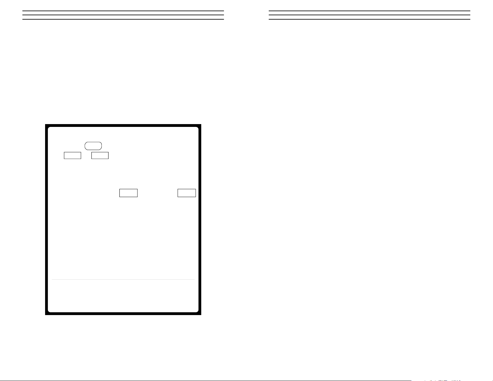
QUICK START OPERATING INSTRUCTIONS
1. Press ON key. LCD display shows
ru.n or run.
2. Place probe tip in contact with part being
checked, pressing down slightly until the
V-notched shell is flush with the surface.
A reading in mils XX.X or microns XXX
will appear.
3. Note reading and lift probe.
4. For additional tests, repeat steps 2 & 3.
11.0 Limited W ar ranty
ELECTROMATIC Equipment Co., Inc. (ELECTROMATIC) warrants to the original
purchaser that this product is of merchantable quality and confirms in kind and quality
with the descriptions and specifications thereof. Product failure or malfunction arising
out of any defect in workmanship or material in the product existing at the time of
delivery thereof which manifests itself within one year from the sale of such product,
shall be remedied by repair or replacement of such product, at ELECTROMATIC’s
option, except where unauthorized repair, disassembly, tampering, abuse or misapplication has taken place, as determined by ELECTROMATIC. All returns for warranty or
non-warranty repairs and/or replacement must be authorized by ELECTROMATIC, in
advance, with all repacking and shipping expenses to the address below to be borne by
the purchaser.
THE FOREGOING WARRANTY IS IN LIEU OF ALL OTHER WARRANTIES,
EXPRESSED OR IMPLIED, INCLUDING BUT NOT LIMITED TO, THE
WARRANTY OF MERCHANTABILITY AND FITNESS FOR ANY PARTICULAR
PURPOSE OR APPLICATION. ELECTROMATIC SHALL NOT BE RESPONSIBLE
NOR LIABLE FOR ANY CONSEQUENTIAL DAMAGE, OF ANY KIND OR
NATURE, RESULTING FROM THE USE OF SUPPLIED EQUIPMENT, WHETHER
SUCH DAMAGE OCCURS OR IS DISCOVERED BEFORE, UPON OR AFTER
REPLACEMENT OR REPAIR, AND WHETHER OR NOT SUCH DAMAGE IS
CAUSED BY MANUFACTURER’S OR SUPPLIER’S NEGLIGENCE WITHIN ONE
YEAR FROM INVOICE DATE.
Some State jurisdictions or States do not allow the exclusion or limitation of incidental
or consequential damages, so the above limitation may not apply to you. The duration
of any implied warranty, including, without limitation, fitness for any particular purpose
and merchantability with respect to this product, is limited to the duration of the
foregoing warranty. Some states do not allow limitations on how long an implied
warranty lasts but, not withstanding, this warranty, in the absence of such limitations,
shall extend for one year from the date of invoice.
GAUGE AUTOMATICALLY POWERS OFF
AFTER 90 SECONDS OF NON-USE
NOTE: This gauge normally doesn't require calibration
before use. To verify or change calibration – or change
units (mils vs. microns) – See User’s Guide
ELECTROMATIC Equipment Co., Inc.
Cedarhurst, NY 11516 – USA
TEL 516-295-4300
• FAX 516-295-4399
–2 –
ELECTROMATIC Equipment Co., Inc.
600 Oakland Ave. Cedarhurst, NY 11516—USA
Tel: 1-800-645-4330/ Tel: 516-295-4300/ Fax: 516-295-4399
Every precaution has been taken in the preparation of this manual. Electromatic Equipment Co., Inc.,
assumes no responsibility for errors or omissions. Neither is any liability assumed for damages
resulting from the use of information contained herein. Any brand or product names mentioned herein are used for identification purposes only, and are trademarks or registered trademarks of their
respective holders
– 15 –
Page 3

10.0 Specifications
2.0 Operating Principle & A pplications
Range: 0.1–40.0 mils (1–999 µm)
Accuracy:
DCF-900 + 0.1 mil : 0–10.0 mils
+ 1% reading : 10.0-40.0 mils
1 µm : 0–250 µm
+
+ 1% reading : 250-999 µm
DCN-900 +
Resolution: 0.1 mil (1 µm)
Battery/Life: 9 Volt Alkaline / Approx.6 months
Dimensions: 5.7 x 3.1 x 1.5" (145 x 79 x 38 mm)
Weight: 9 oz. (250 g)
Temp. Limits: Material: 15 to 140° F (–10 to 60° C)
Cal. Standards: One steel plate (DCF),
Warranty: 1 year
0.1 mil : 0–5.0 mils
+ 2% reading : 5.0–40.0 mils
1 µm : 0–50 µm
+
+ 2% reading : 50-999 µm
Note: Accuracy limits require that
calibration be made near the measured
thickness.
Ambient: 32 to 125° F (0 to 50° C)
One aluminum plate (DCN)
and two plastic calibration shims
2.1 DCF-900
When a magnet is brought into direct contact with a bare magnetic
metal surface, a magnetic flux circuit is created. The amount of
flux created depends on the strength of the magnetizing force and
the magnetic reluctance of the bare metal. A non-magnetic coating
or metal plating placed in the path of a magnetic flux circuit will
create a “magnetic gap” which will increase the reluctance of the
circuit. This will then cause a decrease in the circuit flux, proportional to the thickness of the coating or plating. CHECK•LINE®
Coating Thickness Gauges measure this decrease in flux intensity
to provide an accurate, direct indication of the coating or plating
thickness being measured.
The Model DCF-900 gauge measures the thickness of all non-magnetic coatings, finishes and metal plating on iron, steel and other
magnetic alloy surfaces. (Examples: paint,powder coatings, plastic,
paper, ceramic, rubber, chrome, electroless nickel, brass, non-magnetic stainless steel, tin, zinc, cadmium, etc. . . on iron or steel
2.2 DCN-900
An eddy-current-producing probe brought into direct contact with a
bare metal surface, creates a magnetic flux circuit. The amount of
flux depends on the frequency and strength of the eddy-current
force and the magnetic reluctance of the bare metal. A non-metallic, non-conducting coating placed in the path of a magnetic flux
circuit will create a “magnetic gap” which will increase the reluctance of the circuit. This causes a decrease in the circuit flux, proportional to the thickness of the coating. CHECK•LINE®Coating
Thickness Gauges measure this decrease in flux intensity to provide an accurate, direct indication of the coating thickness.
– 14 –
The Model DCN-900 gauge will measure the thickness of all
non-metallic, non-conducting coatings, finishes and films on all
non-ferrous metals. (Examples: Anodizing, paint, powder coatings,
plastic, paper, ceramic and rubber on aluminum, brass, bronze,
titanium, non-magnetic stainless steel, zinc, etc.)
– 3 –
Page 4

3.0 Equipment Supplied
9.0 Maintenance, Spare Par ts & Serv ice
3.1 Standard Accessories
DCF-900 and DCN-900 gauges are supplied with the following
standard accessories:
a. DCF: One (1) bare steel test plate for setting ZERO.
DCN: One (1) bare aluminum test plate for setting ZERO.
b. Two (2) non-metallic, commercial-grade calibrating shims.
c. One 9-Volt DC alkaline battery.
d. DCF-900 User’s Guide.
e. Carrying case.
3.2 Optional Calibration Standards
a. Model TS-5CG Set of five (5) commercial-grade,
non-metallic, calibration shims (1, 2, 5, 10 & 20 mils /
25.4, 50.8, 127, 254, 508mm).
b. NTS-4 NIST Traceable Plastic Shims
(1.00, 2.00, 4.00 mils / 25, 51, 102mm)
NTS-20 NIST Traceable Plastic Shims
(5.00, 10.00, 20.00 mils / 127, 254, 508mm)
c. NIST Certified Standards
Part# Type Thickness Std’s (mils) Thickness Std’s (µm)
TSF-4 Fe 1.50 2.50 4.00 38.1 63.5 101.6
TSF-20 Fe 2.00 10.00 20.00 50.8 254.0 508.0
TSN-4 NFe 1.50 2.50 4.00 38.1 63.5 101.6
TSN-7 NFe 1.50 3.00 7.00 38.1 76.2 177.8
9.1 Maintenance
Except for keeping all parts clean and replacing worn-out
batteries, there are no special maintenance requirements.
DO NOT USE ANY LUBRICANTS, SOLVENTS OR
ABRASIVES.
A mild soap solution, used sparingly, can be used to clean the
housing and connecting cable. Do not use any water or solvent on
the probe body or tip. Keeping the probe tip clean is critical for
obtaining accurate, repeatable readings. Use a dry cloth to keep the
tip clean. It is recommended that the gauge be stored in its carrying
case when not in use.
9.2 Spare Parts & Service
A complete stock of replacement spare parts and a service facility
are maintained at ELECTROMATIC Equipment Co.,Inc.,
Cedarhurst, NY 11516-USA.
TEL. 800-645-4330 (USA only) or 516-295-4300.
FAX. 516-295-4399
If there are any questions regarding the operation of the DCF-900
or DCN-900 gauge, and before sending any unit back for repair, it
is strongly recommended that the user contact ELECTROMATIC’s
service facility above by telephone or fax.
– 4 –
– 13 –
Page 5

8.0 Changing the Battery
4.0 Fr ont Panel Layout and Functions
The battery should not be removed while the power is on. Wait for the
gauge to automatically power off (after 90 seconds of non-use) before
replacing the battery.
When to Replace: The gauge will automatically turn off if the battery
drops below 7.4 volts DC. If the gauge turns itself off sooner than
expected, or if it will not turn on, change the battery.
Battery Type: Any high-quality 9-volt alkaline battery.
Battery Life: Approximately 6 months when the
gauge is used for 80 readings per day.
Fig Control or
Ref Device Function or Indication
1 LCD Provides measurement value, as well as
display CAL and run indicators.
2 Turns the power on. (The power turns off
3 Enters and exits calibration mode.
4 Sets “zero” calibration point while in CAL mode.
5 Decreases displayed value while in CAL mode.
ON
ON
automatically after 90 seconds of non-use.)
Increases displayed value while in CAL mode.
Changes units of measure from mils to microns
or vice versa while in run mode.
1
– 12 –
4
2
3
– 5 –
5
Page 6

5.0 Operating Pr ocedure
7.0 Changing Units of Measur e
5.1 Handle Probe Carefully.
All probes contain sensitive circuitry. Handle them with care.
Do not drop or swing them.
AVOID DRAGGING PROBE TIP ACROSS A SURFACE.
For best results, hold probe in place until reading is stabilized,
then lift probe away from surface before re-applying to surface
for subsequent readings. Clean pole tips with a dry cloth.
DO NOT USE ANY SOLVENTS.
5.2.Taking Measurements
1. Press key to turn on the power. The LCD will display
ru.n or run. The gauge is now ready to take measurements.
NOTE: The presence or absence of a decimal point on the LCD
display indicates that the gauge has been set for English (mils)
or metric (microns) units, respectively. To change from mils to
microns and vice versa, refer to 7.0.
2. Hold the probe by the black, outer plastic shell and gently press
the tip against the surface to be measured. Use enough pressure
to cause the inner V-notched liner to contact the coated surface
and prevent the probe from rocking.
ON
To change units of measure (mils vs. microns), proceed as
follows:
1. Turn the power on by pressing the key.
The display will show:
ru.n Gauge set for mils (0.001”), or
run Gauge set for microns (µm)
2. Press the key and keep it depressed for approximately
2 seconds until a tone is heard. You will notice that the decimal
point will either appear or disappear, indicating that the units of
measure have changed from mils to microns, or vice versa,
each time the key is pressed and held. Lift probe.
NOTE: Once selected, units of measure will remain unchanged
each time the DCF-900 is turned on and off.
ON
The thickness reading will be displayed on the LCD display.
– 6 –
– 11 –
Page 7

Setting “Calibration” Point
5.3. Notes on Measurements
5. Place the plastic calibration shim on top of the bare metal part
and then place the probe on top of the shim and bare part
combination and measure as before.
Note: the reading and determine if it matches the indicated value of
the shim. If not, press and hold the or keys to increase or
decrease the displayed value until it matches the shim value.
Remove the probe from the test plate. The display will show
CA.L or CAL.
6. Press and hold the key again to enter the “calibration”
CAL
point into the microprocessor and exit the calibration mode.
The display will now show ru.n or run, indicating that
calibration is complete and that you are back in the operational
mode.
You are now ready to take measurements.
6.4 Notes on Calibration
1. If the gauge reads within 0.1 mil or 3 microns
(2%) of the
calibration shim value, it is usually not necessary to change
the calibration since it is within accuracy limits.
2. Use a calibration shim whose thickness is equal to or greater
than the expected coating thickness to be measured.
1. The gauge will automatically turn the power off after 90
seconds of non-use. You cannot turn the power off manually.
2. The DCF-900 and DCN-900 are continuous-reading type
gauges which will provide readings as long as the probe is in
contact with the measured surface. When the probe is removed,
the LCD display will show ru.n or run, indicating that the
gauge is in the operational mode.
If the thickness reading continues to get smaller while the probe
is in contact with the coating, it indicates that the coating is soft
and that the probe is sinking into the coating.
3 If the last digit alternates between two values during a
measurement, the measurement is midway between those
two values.
4. Where the base metal departs greatly in shape, thickness,
texture or material from the metal standards supplied, the user
should always use a sample of the uncoated product bare metal
itself for setting ZERO.
3. If greater reading accuracy is required, calibration and/or
measurements should be performed with the units of measure
set for microns, since “microns” provides greater resolution
than mils. (0.1 mil = 2.5 microns).
– 10 –
–7 –
Page 8

6.0 Calibration
6.3 Changing Calibration
6.1 Introduction
The DCF-900 normally does not require calibration before use.
However, whenever the productor part material to be checked
varies greatly from the steel test plate supplied, in either thickness
or shape, it is best to check or verify calibration by using an
uncoated sample of the actual product or part with one of the calibration shims supplied. Check calibration as noted in 6.2, below,
and change calibration, if necessary, following the procedure of
6.3. If a change is necessary, continue to use the bare part in lieu
of the test plate supplied when checking or changing calibration.
NOTE: Be assured that the calibration checking and hanging
procedures are very simple. They take only a few minutes to
perform and should only be considered when the product material
thickness or shape changes.
6.2 Checking Calibration
1. Turn the power on by pressing the key.
Display will show ru.n or run.
2. Holding the probe by its plastic shell, place the tip on the
uncoated metal part. Gently push the probe shell until the
V-notched sleeve contacts the bare surface. If the display
reads 0.0, proceed to step 3.
ON
1. Turn the power on by pressing the key.
The screen will display ru.n or run, to indicate English (mils)
or metric (microns) measuring units, respectively. To change
units, refer to 7.0.
2. Press and hold the key until CA.L is displayed, to
start the calibration process.
Setting “Zero” Point
3. Holding the probe by its plastic shell, place the tip on the bare
metal. Gently push the shell until the V-notched sleeve contacts
the surface.
The display will read 0.0, or any other value.
4. Maintaining probe contact with one hand, press and hold
the key with the free hand until a beep sounds. This
indicates that the "zero" point is properly set and entered into the
gauge's microprocessor. Remove probe.
CAL
ON
If the display reads any value other than 0.0, proceed no further
since the calibration must be changed, as noted in 6.3.
3. Next, place the plastic calibration shim on top of the bare metal
part and the probe tip on top of the shim and metal part and
measure as in 5.2.
If the displayed value matches the value indicated on the shim,
within the accuracy limits of the DCF-900 Specifications noted
in 10.0, calibration has been verified. THE GAUGE IS
NOW READY FOR USE.
If it differs from the shim value, the gauge should be
re-calibrated, as indicated in 6.3.
– 8 –
– 9 –
Page 9

CHECK•LINE
DCF-900 / DCN-900
Coating Thickness Gauge
®
CHECK•LINE
INSTRUMENTS
®
ELECTROMATIC
E Q U I P M E N T C O., I N C.
600 Oakland Ave., Cedarhurst, NY 11516–U.S.A.
TEL: 516-295-4300 • FAX: 516-295-4399
USER’S GUIDE
 Loading...