

Page 1

CHECK•LINE
®
BY ELECTROMATIC
CTM2 - Quick Check
Cable Tension Meter
Tel: +1 (281) 516-9292 / (888) 275-5772
Web: https
://www.abqindustrial.net E-mail: info@abqindustrial.net
Distributed by: ABQ Industrial LP USA
eFax: +1 (866) 234-0451
Page 2

Dillon is part of Avery Weigh-Tronix. A very Weigh-T ronix is a trademark of the Illinois Tool Works group of companies whose ultimate parent
company is Illinois Tool Works Inc ("Illinois Tool Works"). Copyright © 2014 Illinois Tool Works. All rights reserved.
No part of this publication may be reproduced by making a facsimile copy, by the making of a copy in three dimensions of a two-dimensional
work and the making of a copy in two dimensions of a three-dimensional work, stored in any medium by electronic means, or transmitted in
any form or by any means, including electronic, mechanical, broadcasting, recording or otherwise without the prior written consent of the
copyright owner, under license, or as permitted by law.
This publication was correct at the time of going to print, however Avery Weigh-Tronix reserves the right to alter without notice the
specification, design, price or conditions of supply of any product or service at any time.
quick check red_u_en_501364.book
Page 3

Table of Contents
Chapter 1 General Information and Warnings ........................................................................................ 5
About this Manual ..............................................................................................................5
Text Conventions ........................................................................................................5
Special Messages .......................................................................................................5
Safe Handling of Equipment with Batteries .................................................................6
Routine Maintenance .........................................................................................................6
Cleaning the Machine ........................................................................................................6
Training ..................................... ................................................................ .........................6
Sharp Objects .............................................. ... ....................................................... ... .... .....6
FCC and EMC Declarations of Compliance .......................................................................7
Declaration of Conformity (Quick Check Red) ............. ...................................................... 8
Declaration of Conformity (EDX PSU) ...............................................................................9
Chapter 2 Introduction ............................................................................................................................ 10
Unpacking .................................... .................................................................... ................10
Front Panel and Keys ......................................................................................................11
Important Features .................................... ... ... .... ... ... ... .... ... .............................................12
Using Quick Check (Red) with EDXtreme PSU ...............................................................12
Quick Check Connector ............................................................................................12
External Power Supply ..............................................................................................13
Chapter 3 Operation ................................................................................................................................14
Typical Operation ...... ....................................................... ... ... ... ... .... ... ... ..........................14
Measurement Practices ...................................................................................................15
Softkey Functions ..................... ... ... ... .... ... ....................................................... ... ... ... .... ... 16
Top level Softkeys .....................................................................................................16
Chapter 4 Configuration Mode ...............................................................................................................26
Accessing the Configuration Mode ..................................................................................26
Chapter 5 Changing Sheaves ................................................................................................................. 30
Chapter 6 Achieving Best Accuracy ...................................................................................................... 31
Accuracy ..........................................................................................................................31
Calibration to Specific Wire Type .....................................................................................31
Loading Error ...................................................................................................................31
Non-repeatability .................................... ...................................... ....................................31
Non-linearity ................................. ................................ ................................. ...................32
Wire Characteristics .........................................................................................................32
Chapter 7 Troubleshooting .................................................... .................................................... ............. 33
Quick Check .....................................................................................................................33
EDX PSU .................................................. ... ... .... ...................................................... .... ...34
Chapter 8 Specifications .................................................. .................................................... ................... 35
EDX PSU Power Supply Specifications ...........................................................................36
Quick Check Red User Instructions 3
Page 4

4 Quick Check Red User Instructions
Page 5

1 General Information and Warnings
1.1 About this Manual
This manual is divided into chapters by the chapter number and the large text at the top
of a page. Subsections are labeled as shown by the 1 and 1.1 headings shown above.
The names of the chapter and the next subsection level appe ar at the top of alternating
pages of the manual to remind you of where you are in the manual. The manu al name
and page numbers appear at the bottom of the pages.
1.1.1 Text Conventions
Key names are shown in bold and reflect the case of the key being described. This
applies to hard keys and onscreen or soft keys.
Displayed messages appear in bold italic type and reflect the case of the displayed
message.
1.1.2 Special Messages
Examples of special messages you will see in this manual are defined below. The
signal words have specific meanings to alert you to additional inform ation or the relative
level of hazard.
CAUTION!
This is a Caution symbol.
Cautions give information about procedures that, if not observed, could result
in damage to equipment or corruption to and loss of data.
NOTE: This is a Note symbol. Notes give additional and important information, hints
and tips that help you to use your product.
Quick-Check Red User Instructions 5
Page 6

1.1.3 Safe Handling of Equipment with Batteries
CAUTION: Danger of explosion if battery is incorrectly replaced. Replace only
with the same or equivalent type recommended by the manufactur er. Dispose
of used batteries according to the manufacturer’s instructions.
ATTENTION: Il y a danger d'explosion s'il y a remplacement incorrect de la
batterie, remplacer uniquement avec une batterie du même type ou d'un type
équivalent recommandé par le constructeur. Mettre au rebut les batteries
usagées conformément aux instructions du fabricant.
1.2 Routine Maintenance
IMPORTANT: This equipment must be routinely checked for proper operation
and calibration.
Application and usage will determine the frequency of calibration required for
safe operation.
1.3 Cleaning the Machine
Table 1.1 Cleaning DOs and DON’Ts
DO DO NOT
Wipe down the outside of standard products
with a clean cloth, moistened with water and
a small amount of mild detergent
Spray the cloth when using a proprietary
cleaning fluid
1.4 Training
Do not attempt to operate or complete any procedure on a machine unless you have
received the appropriate training or read the instruction books.
T o avoid the ri sk of RSI (Repetitive S train Injury), place the machine on a surface which
is ergonomically satisfactory to the user. T ake frequent br eaks during prolonged usage.
1.5 Sharp Objects
Attempt to clean the inside of the machine
Use harsh abrasives, solvents, scouring cleaners or
alkaline cleaning solutions
Spray any liquid directly on to the display windows
Do not use sharp objects such as screwdrivers or long fingernails to operate the keys.
6 Quick-Check Red User Instructions
Page 7

1.6 FCC and EMC Declarations of Compliance
United States
This equipment has been tested and found to comply with the limits for a Class A digital device, pursuant to Part 15 of the FCC Rules.
These limits are designed to provide reasonable protection against harmful interference when the equipment is operated in a
commercial environment. This equipment generates, uses, and can radiate radio frequency energy and, if not installed and used in
accordance with the instruction manual, may cause harmful interference to radio communications. Operation of this equipment in a
residential area is likely to cause harmful interference in which case the user will be required to correct the interference at his own
expense.
Canada
This digital apparatus does not exceed the Class A limits for radio noise emissions from digital apparatus set out in the Radio
Interference Regulations of the Canadian Department of Communications.
Le présent appareil numérique n’émet pas de bruits radioélectriques dépassant les limites applicables aux appareils numériques de
la Classe A prescrites dans le Règlement sur le brouillage radioélectrique edicté par le ministère des Communications du Canada.
European Countries
WARNING: This is a Class A product. In a domestic environment, this product may cause radio interference in which the user may be
required to take adequate measures.
Quick-Check Red User Instructions 7
Page 8

1.7 Declaration of Conformity (Quick Check Red)
8 Quick-Check Red User Instructions
Page 9

1.8 Declaration of Conformity (EDX PSU)
Quick-Check Red User Instructions 9
Page 10

2 Introduction
Lever arm
Front panel
Battery compartment
Sheaves
Support arm
This manual covers the setup and operation of the Quick-Check Clamp Line
Tensiometer from Dillon. The Quick-Check is a simple, accurate strand dynamometer.
It is can be clamped onto a cable, accurately determine the wire tension and be
removed in seconds.
The Quick-Check can handle multiple wire diameters, it can display live tension, dual
live/peak tension, average tension captured from several tests, and a check-ten sioning
graphical display.
With its battery-powered electronic interface, setup and operation is made simple with
on-screen prompts.
This manual covers the following:
l Unpacking
l Setup
l Operation
l Maintenance
l Troubleshooting
2.1 Unpacking
When you receive your Quick-Check, unpack it and inspect the contai ner and the
instrument for any damage. Report any problems to the shipping company immediately
and save the packing materials.
Insert 2 AA batteries into the battery compartment, shown in Figure 2.1. Your QuickCheck probably comes from the factory with the proper sheave size insta lled and
calibrated for your application. If not, follow the setup directions later in section 3.0
Configuration Mode and section 4.0 Changing Sheaves.
The Quick-Check is shown in Figure 2.1 with the different parts labeled.
10 Quick-Check Red User Instructions
Figure 2.1 Quick-Check Parts
Page 11

2.2 Front Panel and Keys
The front panel of the Quick-Check is shown in Figu re 2.2. The light located under the
WIRE button illuminates green when changes in the menu are stored, purple when in
diagnostics or uploading firmware and red when powering the unit down.
Figure 2.2 Quick-Check Front Panel
Following are descriptions of the keys and their functio ns :
ON/OFF key. Press this key to power up and turn off the Quick-Check.
ESC key. Press this key to escape an area of the menu or to clear the field when in
data entry mode.
WIRE key. Press this key to change the wire diameter you are testing with the
Quick-Check. Choose from the listed selection and when the desired size is
highlighted, press the ENTER softkey. Up to 20 sizes available.
Soft key. Softkey function changes as needed for different tasks. The soft key
labels appear above the keys themselves. You will use these for operation and
configuration.
Arrow key. Press this key to reveal more softkeys in a group of softkeys.
Quick-Check Red User Instructions 11
Page 12

2.3 Important Features
Quick to use Attaches and removes from tensioned line in
Direct tension readings No more complicated lookup charts! Save time
Portable & rugged Designed for outdoor use.
seconds.
Quick-tensioning readout for ultra fast line
tensioning.
and improve accuracy.
Accurate Employs Weigh Bar
weighing.
Multiple wire size storage Stores up to 20 different calibrations.
®
technology used for precise
2.4 Using Quick Check (Red) with EDXtreme PSU
The Quick Check can be connected to the EDX PSU via the Comm Port. This 120VAC/
240VAC external power supply will supply power to the Quick Check instead of AA
batteries.
2.4.1 Quick Check Connector
The connector on the Quick Check is recessed for protection. Lift the protective cap to
access the connector. It is used to connect the instrument to a printer, PC or external
power supply . See your Dillon distributor for deta ils.
12 Quick-Check Red User Instructions
Figure 2.3 Quick Check Connector
Page 13

2.4.2 External Power Supply
Plug the 4-pin end of the power supply cable into the Quick Check 4-pin connector
located on the side of the unit. Plug the power supply adapter into an AC power outlet.
Refer to Figure 2.4 for a photo of the external power supply.
Figure 2.4 External Power Supply Connection
Figure 2.5 External Power Supply (EDX PSU) (120 - 240 VAC 50 - 60 Hz)
Quick-Check Red User Instructions 13
Page 14

3 Operation
Zero
Clear
Mode Store
lbf
7/16 6X19
Shv:S
Unit of
Measure
Battery
level
Wire
size
Sheave to
be used
Tension of
rope reading
Typical operation of the Quick-Check is covered below , followed by explanations of the
various display modes, how to change wire size, how to change the unit of measure,
etc.
3.1 Typical Operation
To perform a typical tension measurement, see the note below and follow these steps:
Take readings at three different places along the cable, moving the tension meter at
least four inches for each reading. Take the average of the readings. The built-in
average function is ideal for this task.
The handle quick release pin should be used when the Quick-Check is attached to a
cable that will be de-tensioned and re-tensioned. The pin prevents the handle from
opening once the tension falls to a small level. The pin should also be used if the
Quick-Check will be installed for a prolonged period.
1. Turn the unit on by pressing the ON/OFF key…
The display shows DILLON briefly, then, in this example, the screen
shows the following:
Figure 3.1 Sample Display
Press the WIRE key to list the stored calibrations.
2. This example shows the wire is a 7/16”, 6X19 stranded cable using the “S”
Sheave and the unit of measure is lbf. Place the Quick-Check so the two
outside sheaves hang on the wire. Insure that the wire rope is riding in the
center groove for all three sheaves. See Figure 3.2. Press the Zero softkey to
zero the display.
3. Raise the lever arm until it locks in the upright position to apply tension to the
wire. Read the line tension on the display.
14 Quick-Check Red User Instructions
0 should be displayed.
Page 15

4. Release the lever arm and you are ready to perform another measurement.
Figure 3.2 Quick-Check Attached to Cable
3.2 Measurement Practices
For best measurement, install the Quick-Check at least 2 feet (0.6 m) from
terminations, clamps or other hardware. Do not install over the top of wire wrappings.
Take readings at three different places along the cable, moving the tension meter at
least four inches for each reading. Take the average of the readings. The built-in
average function is ideal for this task.
WARNING: Do not apply tension greater than rated capacity of the instrument
or overload damage to the sensor may result. Do not us e the Quic k- Ch eck with
cable larger than indicated on the sheaves. Overload and damage to the
instrument may result. Do not mix sheave sizes. This will result in inaccurate
measurement and possible overload.
Do not use the Quick-Check to measure tension for wires if any of the following are
true:
1. No wire calibrations are stored of the same diameter as the wire you are lo oking
to measure, and/or
2. You do not have sheaves of the same diameter.
If both of these conditions exist, contact your Dillon distributor.
Contact your Dillon distributor to improve accuracy for a specific wire type by calibrating
to it.
Insure that the wire rope is riding in the center of the groove for all three sheaves.
Quick-Check Red User Instructions 15
Page 16

Insure sheaves installed agree with sheaves noted in the Wire calibra tion. Exception:
Zero
Clear
Mode Store
Press
Units
Log
Setup
Config
lbf
7/16 6X19
Shv:S
lbf
7/16 6X19
Shv:S
Sheaves match the wire diameter of the cable to be measured and alternate calibration
is selected as per section 5.2.
The Quick-Check has an internal temperature sensor inside the electronics cavity.
Dramatic temperature changes (such as moving from a warm vehicle to cooler
outdoors) requires time for the sensor to reach the same temperature. Direct sunlight
will heat the electronics cavity and cause higher readings than actual ambient
temperature. NOTE: The temp erature is only for the Quick Check electronics and
does not compensate for the temperature of the wire rope.
For best tension accuracy, use the exact temperature of the wire along with the cable
manufacturer’s temperature compensation chart. This may be widely different from the
ambient temperature if the cable has been sitting in direct sunlight.
3.3 Softkey Functions
Now that you’ve seen a simple operation, we’ll explain the softkey functions. Figure 3.3
shows the softkeys available during normal operation.
3.3.1 Top level Softkeys
At any time, press the ESC key to return to the normal operating mode. If changes ha ve
been made to the configuration, you will be prompted to save them (Yes) or abort the
changes (No) before exiting the configuration mode.
Zero
Press this softkey to zero the force display. You would usually press this at the
beginning of a series of tension tests but would not need to do it for every test unless
there is some zero drift.
Clear
Press this softkey and you are prompted to clear the Peak reading or the Average.
Make your choice by pressing the appropriate softkey and that value is cleared from
memory.
Figure 3.3 Normal Mode Softkeys
16 Quick-Check Red User Instructions
Page 17

Mode
UNDER
1960
5700
lbf
7/16 6X19
Shv:S
lbf
7/16 6X19
Shv:S
Display when tension
is below the dotted,
target box.
Display when tension
falls within the dotted,
target box.
Press the Mode key to scroll through the four display modes. These are explained
below:
Live Tension Mode: The display shows the live tension.
Dual Peak Mode: The display shows the live tension on the top display and the peak
force achieved on the bottom display. To clear the peak, remove any force on the
Quick-Check, press the Clear softkey and follow the prompts.
Average Capture Mode: This mode shows the live tension in the top display and the
average of all captured readings on the bottom display. To capture a reading and add
it to the average, press the Store softkey whe n a fo rc e is ap plied to the Quick-Check.
Follow the prompts to add (or not) the reading to the average. NOTE: Must set
Log>Setup to Disabled for the Average Mode to work.
Check-tensioning Mode: Check-tensioning mode permits quick & easy graphical view
of the applied tension versus the desired tension. This mode works well when you are
repeatedly tensioning to the same tension range. This mode displays a bar graph
representation of the tension being applied. See Figure 3.4. The black bar represents
the range of the wire, from zero to ultimate wire rating. The wide white band is the
tolerance window based on upper and lower thresholds you can ente r . The live force is
represented by the arrow and the white line on the black bar . When the force gets within
±5% of the acceptance window , a close-up of the acceptance window is displayed. See
bottom example in Figure 3.4.
NOTE: Upper and lower thresholds are set in the Configuration WIRE menu. See
page 27.
The Quick-Check has automatic tension targeting. Point s may be entered from a linear
Tension supplied table for a wire cable.
Figure 3.4 Check Tension Display
To exit the check-tension mode, press any softkey to display the softkey labels, then
press the Mode softkey to scroll to the next mode. The next mode is the first mode that
was described, live tension mode.
Quick-Check Red User Instructions 17
Page 18

Store
Log
Setup ID Send Clear
Log Mode
Disable On Print On Lift Timed Overload
Auto ID increment
(Enabled,
Disabled)
Auto ID prompt
(Enabled,
Disabled)
Log rate (sec)
1
Log count
(1 to 255)
Auto send
(Disabled,
Enabled)
Comm port
(Disa b le d , Cell,
COM1, RADIO)
Threshold%
10
Re-arm%
2
Auto ID increment
(Enabled,
Disabled)
Threshold%
5
Re-arm%
2
Holdoff Seconds
1
Comm port
(Disabled, Cell,
COM1, RADIO)
Comm port
(Disab led , Ce ll,
COM1, RADIO)
ONLY APPEARS
IF AUTO ID
INCREMENT IS
DISABLED
Auto send
(Enabled,
Disabled)
Comm port
(Disabled, Cell,
COM1, RADIO)
Multi Leg/Wire
Max Legs
(0-9)
Max Wires
(0-30)
Comm port
(Disabled, Cell,
COM1, RADIO)
Press the Store softkey to store and add a displayed tension to the average of other
entered readings. Follow the onscreen prompts.
When Multi Leg/Wire is enabled in Log>Setup menu, each leg is identified by a letter
rather than a number (A - I). Each tension wire (guy wire) is iden tifie d by a numb er.
When the Store sof tkey is pressed, leg with be displayed. If more than one le g, use the
Sel keys to select the desired Leg. Press Enter to go to the wire selections. Use the
Num keys to select the wire number. Press Enter to store the tension reading. Refer
to page 21 for more details.
Press the key to move to the next set of softkeys.
Units
Press this key to set the Quick-Check for displaying:
l Force in lbf, kgf or N
Log
Log mode is used to log/record force and peak data. Press this softkey to view the
number of records logged. This can be done on each lift, durin g a timed duration, during
an overload or on Print key operation.
Figure 3.5 Log Menu
18 Quick-Check Red User Instructions
Page 19

Note: All Log Modes will record Date and Time along with it's force and peak reading.
Setup:
Setup allows the user to configure how the Quick Check stores data internally. This
stored data can be downloaded via the 4 pin Lemo to a PC via a keyboard wedge or
other device.
l Log Mode:
Disable: Turns the log feature off.
On Print: Used when the operator wants to do a lift and store of the force
and peak.
Auto ID Increment
: Enable/Disable
This will increment the ID by 1 every time the "PRINT" key is
pressed and store it with each force and peak.
Auto ID Prompt
: Enable/Disable (will only appear if Auto ID
Increment is Disabled)
If "Enabled", the operator will be prompted to key in an ID before
storing that ID with the force and peak.
Comm Port
:
This allows you to choose where to export the "ON PRINT" logged
data.
a. Cell = Setup Cell for data export (4 pin Lemo)
b. Com1 = Not used
c. RADIO = Future development
d. Disabled = to turn off
On Lift: Used when the operator wants the load to be automatically
stored, once the load becomes stable. Note: additional filtering may be
required, as the load must be steady before the load will be recorded.
Maximum Records = 255
Threshold %
: (based on capacity)
This is the load above where the unit will record the stable load.
Quick-Check Red User Instructions 19
Re-arm
: (based on capacity)
This is the load the force must drop below before the "ON LIFT"
will reset (re-arm) and store another load.
Auto ID Increment
: Enable/Disable
This will increment the ID by 1 every time the "PRINT" key is
pressed and store it with each force and peak.
Auto Send
: Enable/Disable
Can export the readings live if enabled.
Page 20

Comm Port:
This allows you to choose where to export the "ON PRINT" logged
data.
a. Cell = Setup Cell for data export (4 pin Lemo)
b. Com1 = Not used
c. RADIO = Future development
d. Disabled = to turn off
Timed: This is used when the operator wants to record a live load/pull and
store it internally. Can store up to 255 force readings.
Log Rate
:
The speed at which the logging of force will be recorded. Based
on seconds (Example 5 sec = Unit will record the force once every
5 seconds)
Log Count
:
This is how many logs the operator wants to record. Range is 0 to
255 recorded readings.
Auto Send
: Enable/Disable
Can export the readings live if enabled.
Comm Port
:
This allows you to choose where to export the "ON PRINT" logged
data.
a. Cell = Setup Cell for data export (4 pin Lemo)
b. Com1 = Not used
c. RADIO = Future development
d. Disabled = to turn off
Overload: This is used when an operator or supervisor wants to know if
their equipment is being overloaded. This will be a percentage based on
capacity and will be below 100% of the Quick Check. (This not the same
as the 120% overload that the Quick Check records based on capacity.)
Maximum Records = 255
20 Quick-Check Red User Instructions
Threshold %
: (based on capacity)
This the percentage above where the unit will record the peak
load.
Re-arm %
: (based on capacity)
This is the load percentage the force must drop below before the
"OVERLOAD" will reset (re-arm) and store another load.
Holdoff Seconds
:
Once the unit has recorded this overload, how much time will pass
before this unit will re-arm and allow to record the overload again.
Page 21

Comm Port:
This allows you to choose where to export the "ON PRINT" logged
data.
a. Cell = Setup Cell for data export (4 pin Lemo)
b. Com1 = Not used
c. RADIO = Future development
d. Disabled = to turn off
Multi Leg / Wire: This is used to measure tension on tower guyed wires.
The readings can be stored (refer to page 18).
Max Legs
:
Enter the number of legs the tower has.
Max Wires
:
Enter the number of guy wires each leg has.
Comm Port
:
This allows you to choose where to export the "ON PRINT" logged
data.
a. Cell = Setup Cell for data export (4 pin Lemo)
b. COM1 = Not used
c. RADIO = Future development
d. Disabled = to turn off
Quick-Check Red User Instructions 21
Page 22
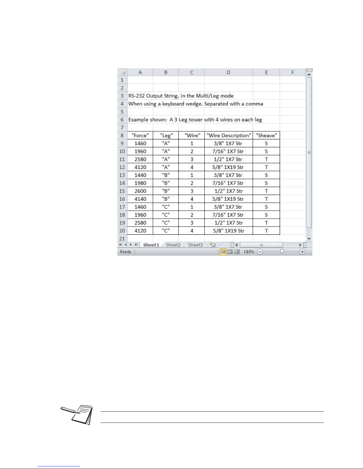
The data will be exported to a computer via RS-232. Dillon
recommends using “WedgeLink” software as a keyboard wedge.
The data needs to be comma delimited and can be expor ted to an
Excel spreadsheet. Refer to Figure 3.6 for an example.
Figure 3.6 Example of Tower Data
ID:
An operater can key in either a User ID number or a Lift ID assigned to a particular
product. This is a numeric number only and can be any number from 1 to 65,000. (if
you want to turn the ID off, key in 0).
Note: ID not used in Multi Leg/Wire mode.
Send:
This will export/send the Log information out the configured port.
Clear:
This will clear any data in the Log mode. Clearing "On Lift", "Timed", "Overload" and
Multi Leg/Wire stored data.
Auto-off can preserve battery life.
22 Quick-Check Red User Instructions
Page 23

Setup
Setup
Power PtFmt Misc. About Test
Batt A-D Disp Keys Comm Setpts
Setpt1 Setp t2
Cell COM1
Press KEY to
test. Press ESC
key to exit
View Counts and
Cal. factor
Run display test
View Battery
Voltage
Device Calib. 0.Load Zero Ntwrk
View Radio
information
View Dead load
Analysis
View Over load
counter and log
Points Re-Cal Print
Print Calibration
report
To view when
calibration is due
View all
Calibration
points
Display Device
info, SN, FW and
PN
Flash Zero Contr BLite
Inten Mode
Selected
Backlight ON,
OFF or Timer
operation
If Timer enabled
then: Enter time
in Seconds
Choose Motion
Reset Timer:
(Yes or No)
Choose backlight
intensity: 1- 10
Adjust Contrast
Up or DOWN
Choose Zero Key
clears Peak:
(Yes or No)
Set AZT (div): .5
Set Motion
Range (div): 1
Enable Key
Blink:
(Yes or No)
Choose default
print format: 1 - 5
Set Filter
(*40)
Date/Time
(Enabled,
Disabled)
Peak Capture Rate:
(100Hz – Normal),
(1KHz – High Speed),
(10Hz – Battery Saver)
Enable Auto-
Shutdown:
(Yes or No)
RADIO
Clock
Press the Setup softkey and you will see these choices; Power, PtFmt, Misc, About,
Test and Clock. These are described below:
Figure 3.7 Setup Menu
Power:
Use this to set power management features
l Peak Capture Rate - Select a Peak Capture Rate by using the Sel keys to
scroll through the choices. Choices are 100Hz - Normal, 1kHz - High
Speed, and 10Hz - Battery Saver (default). Press Enter to accept the
displayed setting.
Be aware that 1kHz - High Speed mode will consume more battery power.
Quick-Check Red User Instructions 23
Page 24

l Enable Auto-Shutdown - Auto-Shutdown powers off the instrument
automatically. If Yes is chosen, the following options will be displayed:
Shutdown Timer (Min): Program to shut down after a period of
inactivity.
Shutdown Type: Select a method of shutdown.
Fixed
: Set the amount of time for the unit to shut off
No Load
No Change
: No load of the tension meter
: No change in weight
PtFmt:
l Default Print Format
l Print time and date
Misc:
Press this softkey to set the following:
l Flash - Enables or disables the momentary blinking of the display to
acknowledge a key press.
l Zero - Enables the use of the Zero softkey to clear a peak tension value.
l Contr - Press this key to adjust the contrast of the LCD display. Press the
Up soft key to lighten the contrast. Press the Down softkey to darken the
contrast.
There is a keypad shortcut for increasing and decreasing contrast. While
in normal display mode press the Arrow key and the 2nd softkey
simultaneously to increase contrast. Press the Arrow key and f irst softkey
simultaneously to decrease contrast.
l Blite - Press this key to adjust the backlight brightness and sleep timer
functions.
Inten- Backlight intensity can be set to a value of 1 - 10. Default
backlight value is 1.
Press Arrow key and F4 simultaneously to increase intensity.
Press Arrow key and F3 simultaneously to decrease intensity
Mode- Select Backlight to operate as always “On”, “always Off” or
the backlight can operate from a configurable “Timer”.
If set to Timer, the operator will be asked to enter the Time in
Seconds, after motion stops that the backlight will shut off.
The next selection will allow the user to configure if motion resets
timer. Choose Yes or No to have motion reset the Timer which
turns off the backlight.
Use of the backlight will affect battery life.
24 Quick-Check Red User Instructions
Page 25

About:
Press this softkey to see the following information:
l Device - Press this softkey to show a list of information about the Quick-
Check; serial number, capacity rating, hardware and software revision
levels. Press any key to return to the previous softkey set.
l Calib - Press this softkey to show Calibration Points and the calibration
information for the current wire size. Follow the on-screen prompts.
l O. Load - Press this softkey to show an audit count of the number of times
the unit has been overloaded beyond 120% of capacity and the actual hour s
the unit is on (On Time). Press any key to return to the previous softkey set.
l Zero - Press this softkey to show the deadload analysis of the Quick-Ch eck.
Press any key to return to the previous softkey set.
l Ntwrk - Displays network information (Radio, Name, ID#). Future
development.
Test:
Press this softkey and the following softkeys appear:
l Batt - Press this softkey to test the battery level.
l A-D - Press this softkey to display the A to D counts.
l Disp. - Press this softkey to perform a test of the display pixels.
l Keys - Press this softkey to test the keypad.
l Comm - Press this softkey to test the RS-232 in a loopback test (Cell).
Com1 is not used.
l Setpts - Not used in the Quick-Check.
Clock
Enter the date and time. Use the Num softkeys to en ter the correct number and use
the Adv softkey to advance the cursor. When the entry is correct, press the Enter
softkey.
Config
This is a password protected menu. See Configuration Mode on page 26.
Quick-Check Red User Instructions 25
Page 26

4 Configuration Mode
Units Log
Setup Config
lbf
7/16 6X19
Shv:S
4.1 Accessing the Configuration Mode
You need to access the Configuration mode to perform certain tasks. Access to some
of these tasks may be restricted by a supervisor password.
To access Configuration mode:
1. From normal operating mode, press the Right Arrow softkey…
A new softkey set, shown below, appears:
2. Press the Config softkey…
The following is displayed:
The Num keys increment and decrement the displayed numbers. The Adv key
moves the cursor to the next digit position.
Default Configuration password is 0. If a new password is lost or forgotten, contact
your Dillon distributor.
3. Use the Num and Adv keys to enter the Config password. Default is 0. After
the number is displayed, press the Enter key…
26 Quick-Check Red User Instructions
The following is displayed:
Page 27

4. The unit is now in the Configuration mode. To see the rest of the softkeys
available in this mode, press the Right Arrow key. All the Config softkeys are
shown below.
The softkeys in the Configuration mode are Wire, Setup, Reso, Comm, Mode, Units,
Power, ChPwd, and Reset. These are described below:
Wire
Press this softkey a nd the wir e sel ecti on sc reen is displ ayed. Choose an e xisting wire
to change its defining characteristics.
Y ou have the choice of changing th e Range, which is used to set the check-tensioning
function, or the Rating, which is the maximum rating of the cable.
l Range - Use this item to set the parameters for the check tensioning display .
Follow the prompts to set the following:
Lower tension limit - This is the lowest acceptable force
Upper tension limit - This is the highest acceptable force
Units - Unit of measure used in defining the tension limit
l Rating - Press this softkey and you are prompted to set the ultimate ratin g
for the cable being used and the unit of measure for that rating.
Setup
Press the Setup softkey to view the Setup softkeys. This is the same as the Setup
softkey described inTop level Softkeys on page 16.
Reso
Press the Reso softkey and you are prompted to enter a display, or count-by,
resolution. Choose from Low, Medium or High.
Low resolution provides the best stability and makes the display easiest to read. High
resolution provides the finest graduations, but sees greater drift from wire creep and
non-repeatability. If the reading is decreasing over time or differing between
measurements on the same line, lowering the resolution will reduce these effects.
Quick-Check Red User Instructions 27
Page 28

Comm
Communication output (COM1) and RADIO are not supported at this time in the QuickCheck. Press the COMM key to select Cell.
l Cell - Press this key to configure the RS-232 port (4 pin Lemo)
l COM1 - Not used
l RADIO - For specials and future development
Mode
Press this softkey to set the display mode on power up. Choices are Last*, Check,
Avg, Peak, and Force. Use the Sel keys to display your choice and press Enter to
accept it.
Units
Press this softkey to set the following:
Unit of measure on power up - Choices are Last*, C2, C1, N, kgf, and lbf. Use the
Sel keys to display your choice and press Enter to accept it. C2 and C1 are custom
units. If you choose to have custom units, you are prompted to enter the number of
pounds in each custom unit. The Quick-Check will then automatically calculate correct
display for the applied force.
l Enable lbf - Enable or disable the pound-force unit of measure.
l Enable kgf - Enable or disable the kilogram-force unit of measure.
l Enable N - Enable or disable the N unit of measure.
l Enable CUST1 - Enable or disable the Cust1 unit of measure.
l Enable CUST2 - Enable or disable the Cust2 unit of measure.
Custom units of measure are handy when working with multi-part lines.
Power
Press this softkey to set the Peak Capture Rate and enable or disable the Autoshutdown.
Select a Peak Capture Rate using the Sel key to scroll through the choices. Choices
are 100Hz - Normal, 1kHz - High Speed, and 10Hz - Battery Saver (default). Press
Enter to accept the displayed setting.
Be aware that 1kHz - High Speed mode will consume more battery power.
If you enable Auto-shutdown, you are prompted to set a period of time in minutes. Next,
press the Enter softkey to accept this value. You are then asked to set the shutdown
type; Fixed, No Load, or No Change. These are described below;
28 Quick-Check Red User Instructions
Page 29

l Fixed - The unit will shutdown after the set number of minutes no matter
what happens.
l No Load - The unit will shutdown after the set number of minutes only if
there is no load on the unit. This prevents shutdown in the middle of line
tensioning.
l No Change - The unit will shutdown if there has been no keypad activity or
change in tension after the set number of minutes.
ChPwd
Press this key and you are prompted to enter a new password to access the
configuration menus. Use the softkeys to scroll in a new password and press the Enter
softkey to accept it.
Default password is 0. If a new password is lost or forgotten, contact your Dillon
distributor.
Reset
Press this key and you are asked if you wish to reset the system. Press the Yes softkey
only if you want to reset the unit to factory default configuration. Press the No softkey
to abort this and return to the previous screen.
Quick-Check Red User Instructions 29
Page 30

5 Changing Sheaves
Screws
Do not use the Quick-Check with cable larger than indicated on the sheaves.
Overload and damage to the instrument may result.
Do not mix sheave sizes. This will result in inaccurate measurement and possible
overload.
As you use the Quick-Check on different diameter cables you must change to the
correct sheave size. To change sheaves, remove the hex head screws pointed out in
Figure 5.1 below. Replace the sheaves with the correct letter sheave and reinsert the
screws and tighten.
Insure sheaves installed agree with sheaves noted in the Wire calibration.
Exception: Sheaves match the wire diameter of the cable to be measured and
alternate calibration is selected as per the section Calibration to Specific Wire Type on
page 31.
Insure that the wire rope is riding in the groove of all three sheaves.
30 Quick-Check Red User Instructions
Figure 5.1 Changing Sheaves
Page 31

6 Achieving Best Accuracy
6.1 Accuracy
The Quick-Check is an instrument designed to give accuracy that typically exceeds
normal requirements for wire tensioning. You should have an understanding of what
factors affect tension measurement accuracy.
6.2 Calibration to Specific Wire Type
While it is best to have the instrument calibrated to the specific wire size(s) and type(s)
used, the Quick-check can often work adequate ly in other situations. If the best tension
accuracy is required, Dillon recommends that a calibration be performed for that
specific wire size and type.
Contact your Dillon distributor for any additional calibrations you may need.
Do not use the Quick-Check to measure tension for wires if either of the following are
true:
1. No wire calibrations are stored of the same diameter as the wire you are lo oking
to measure, and
2. You do not have sheaves of the same diameter.
If either of these conditions exist, contact your Dillon distributor.
Contact your Dillon distributor to improve accuracy for a specific wire type by calibrating
to it.
6.3 Loading Error
A tensiometer works by deflecting the cable, which makes the cable path longer than
when a tensiometer is not installed. When the tensiometer is r emoved, the wire tension
decreases as the cable length is restored. This effect is known as loading error. The
Quick-Check design elongates the cable by a mere 0.08 inch (2 mm), ma king load ing
errors extremely small.
6.4 Non-repeatability
The Quick-Check’s sheave with bearing design provides the best mechanical
performance. It is also superior at detecting tension that is being added or removed.
Quick-Check Red User Instructions 31
Page 32

6.5 Non-linearity
Most three-point tension meters employ only linear characterization and have large
errors at the midpoints (up to 15%). The Quick check uses multi-point segmenting to
correct for non-linearity , reducing it to less than 0.2%.
6.6 Wire Characteristics
Creep Every material including steel exhibits creep under load. It will neck down
over time, quite quickly over the first few seconds and much slower as time
progresses. A wire cable also sees creep from the wire spa cing and wind.
This effect is seen as a display that drifts lower after it has been clamped
in line.
Variations Material that varies in diameter or shape will have different output at the
same tension
Strands The best cable assembly is one that is perfectly round, as it will not change
contact geometry with the wire twist. The closer the wire cable cross
section appears to be round, the better the measurement performance will
be.
32 Quick-Check Red User Instructions
Page 33

7 Troubleshooting
7.1 Quick Check
Problem Possible Cause Solution
Powers on momentarily and turns off Low battery Replace with high quality alkaline batteries
Bad keypad Have unit serviced
Does not power on Low battery Replace with high quality alkaline batteries
Batteries installed
backwards or no spring
contact
Software reset Remove battery cap & reinstall after one minute. Attempt to
Display contrast too
light
Bad keypad Have unit serviced
Display is completely dark Display contrast too
dark
Display drifts downward once installed Wire material is
creeping and internal
friction between wires
is relieved.
Insure that positive terminals of both batteries (nub) face
inward – towards the black cap. Check that spring is attached
to the battery cap.
turn power on again.
Hold the Right Arrow key down while pressing the F2 key
several times to increase the display contrast. If nothing
occurs, release both keys. Press the power button and try
again.
Hold the Arrow key down while pressing the F1 key several
times to decrease the display contrast.
This is normal behavior of wire. Lower display resolution to
mask this effect.
Quick-Check Red User Instructions 33
Page 34

7.2 EDX PSU
Problem Possible Cause Solution
Quick Check powers on
momentarily and turns off
Quick Check does not power onLow battery
Display is completely dark Display contrast too dark Hold the Arrow key down while pressing the F1 key several times to
Quick Check does not
appear accurate
Radio communications not
working at all
Remote reading changes to
dashes
Display locks up on
DILLON marquee
Low battery
Bad keypad
Bad keypad
Batteries installed
backwards or no spring
contact
Software reset Remove battery cap & reinstall after one minute. Attempt to turn power on
Display contrast too light Hold the Right Arrow key down while pressing the F2 key several times to
EDX PSU Power Supply Remove Power Supply and install batteries to see if the Quick Check or
Check installation &
system
Local gravitational
variances
Check repeatability Place Quick Check in low-resolution mode. Lift an arbitrary weight several
Compare against a
reference load.
Dead batteries. Distance
is excessive, dead radio
pocket
Operating channels mismatched
Excessive radio noise or
interference in
environment
Low batteries, lost
communications
Poor connection
between Quick Check
and Communicator
Replace with high quality alkaline batteries. Do not use rechargeable
batteries.
Have unit serviced.
Replace with high quality alkaline batteries. Do not use rechargeable
batteries.
Have unit serviced.
Insure that positive terminals of both batteries (nub) face inward –
towards the black cap. Check that spring is attached to the battery cap.
again.
increase the display contrast. If nothing occurs, release both keys. Press
the power button and try again.
Communicator II will power up. Return EDX PSU to factory for repair/
troubleshooting.
decrease the display contrast.
Insure that shackles are in good working condition and aligned straight.
Verify system is applying force directly through the dynamometer with no
off center or torsional loads being applied to the instrument.
If being compared against dead-weights, check your local gravitational
constant. Use custom units to compensate or calibrate on-site.
times as close to capacity as possible. Record each weight reading. Do
the readings differ from each other? Calculate the standard deviation of
the readings using a spreadsheet such as Microsoft Excel. See if the
deviation is greater than 0.1% of the instrument capacity.
Place Quick Check in low-resolution mode. Apply a known load near
instrument capacity. Check calibration date.
Bring remote closer to dynamometer. Allow several seconds to retrain.
Remote and link must be on the same operating channel. See Quick
Check and Communicator configurations of COM1 for radio (under Comm
menu) and Common Configurations.
Remove dynamometer and Communicator from the environment. Attempt
communications in an area free of local radio signals. See Radio
Information section of the manual.
See steps above for improving communications.
Remove batteries from Quick Check and Communicator, replace them
and power up.
34 Quick-Check Red User Instructions
Page 35

8 Specifications
Power
2 AA, common alkaline batteries.
Display
Dot graphic LCD display
Operational Keys
Power, Wire, Escape/Clear (ESC), Next ( ) and four softkeys with changing
function and label, depending on the specific menu in use
Operational Annunciators
Unit of measure, battery level
Display Resolution
2,000 lbf/ 10 kN/ 1000 kgf Quick-Check instrument:
Displayed resolution setting
Low Med High
lbf (pound-force) 10 lbf 5 lbf 2 lbf
kgf (kilogram-force) 5 kgf 2 kgf 1 kgf
N (Newton) 50 N 20 N 10 N
Custom units between 101 & 200
divisions
10,000 lbf/ 45 kN/ 4500 kgf Quick-Check instrument:
Low Med High
lbf (pound-force) 50 lbf 20 lbf 10 lbf
kgf (kilogram-force) 20 kgf 10 kgf 5 kgf
N (Newton) 200 N 100 N 50 N
Custom units between 101 & 200
divisions
between 201 & 500
divisions
Displayed resolution setting
between 201 & 500
divisions
between 501 & 1000
divisions
between 501 & 1000
divisions
For ease of use, the display always counts by a multiple of 1, 2 or 5.
Quick-Check Red User Instructions 35
Page 36

Available Options
Varied wire sizes
Operating Environment
Suitable for outdoor use
Dimensions
10˝ x 23˝ x 3˝ (25 cm x 59 cm x 8 cm) approximately
Weight
11 lb (5 kg) approximately
8.1 EDX PSU Power Supply Specifications
Enclosure Designed for indoor use
Input Voltage 100-240 VAC 50-60Hz, 0.55A
Output Voltage 5 VDC
Operating Temperature -4 F to 158 F (20 to 70 C)
Connector Sealed connector to be used with Quick Check
Approval CE
36 Quick-Check Red User Instructions
Tel: +1 (281) 516-9292 / (888) 275-5772
Web: https
://www.abqindustrial.net E-mail: info@abqindustrial.net
Distributed by:
ABQ Industrial LP USA
eFax: +1 (866) 234-0451
 Loading...