

Page 1
- 1 -
CONTENTS
1.0 Introduction . . . . . . . . . . . . . . . . . . . . . . . . . . . . . . . . . . . . . . . . . . . . . . . . . . . . . . 002
1.1 Complete Kit
2.0 Overview . . . . . . . . . . . . . . . . . . . . . . . . . . . . . . . . . . . . . . . . . . . . . . . . . . . . . . . . . 03
2.1 Key Function
2.2 Main Display
3.0 Accessing Secondary Functions . . . . . . . . . . . . . . . . . . . . . . . . . . . . . . . . . . . . . .
05
3.1 Function Table
3.2 Changing the value of the selected function
3.3 Moving through the Function Modes
4.0 Operation . . . . . . . . . . . . . . . . . . . . . . . . . . . . . . . . . . . . . . . . . . . . . . . . . . . . . . . . 08
4.1 Preparing for testing
4.2 Changing the Units of Measure
4.3 Selecting the Measuring Mode
4.4 Comparator functions
4.5 Setting the HI and LOW values
4.6 Zero Function
4.7 Saving data in memory
4.8 Recalling stored memory
4.9 Clearing stored data
5.0 Specifications . . . . . . . . . . . . . . . . . . . . . . . . . . . . . . . . . . . . . . . . . . . . . . . . . . . . . 15
6.0 Dimensional Drawings . . . . . . . . . . . . . . . . . . . . . . . . . . . . . . . . . . . . . . . . . . . . . 16
7.0 Warranty . . . . . . . . . . . . . . . . . . . . . . . . . . . . . . . . . . . . . . . . . . . . . . . . . . . . . . . . 17
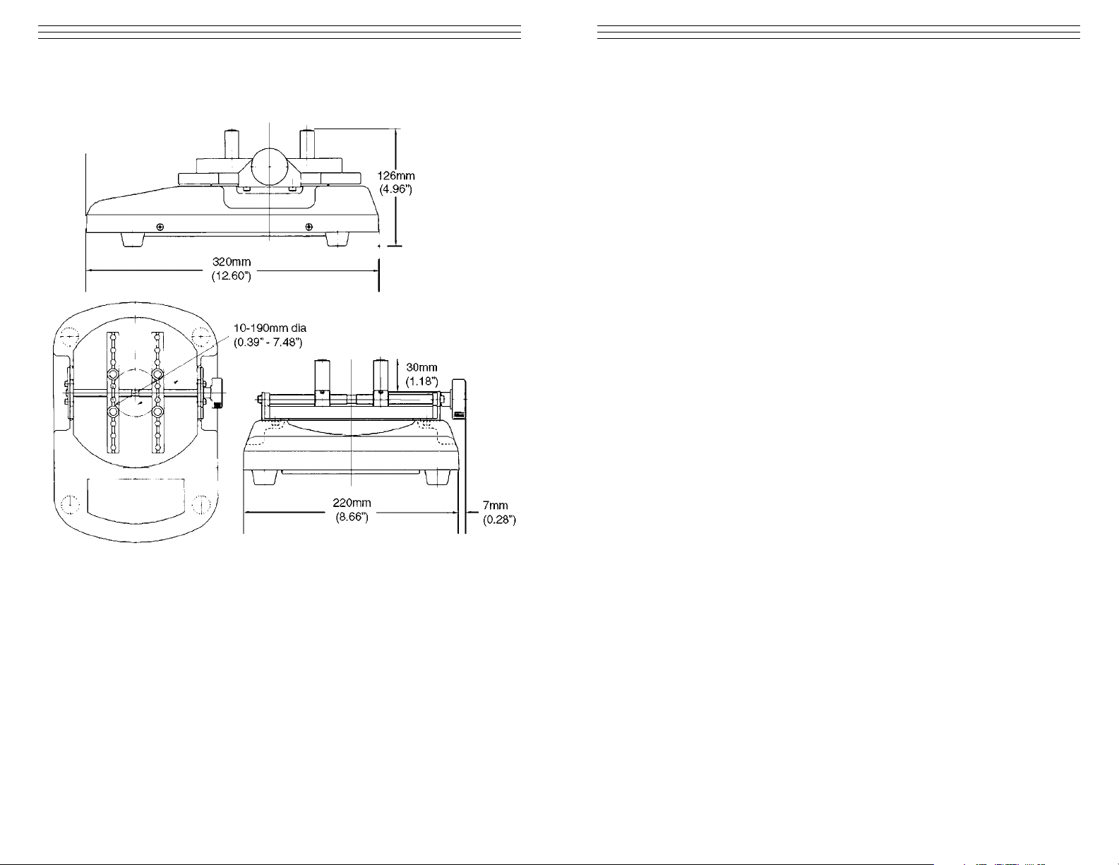
- 16 -
6.0 DIMENSION DRAWINGS
OI308TNP
Page 2
- 2 -
1.0 INTRODUCTION
Thank you for choosing the CAP-TNP digital torque tester, with proper care this
unit will provide many years of reliable service.
The CAP-TNP torque meter is a portable device that can be used as a quality
assurance tool for various applications that requires turning (both opening and
closing) and twisting.
Some fields that can utilize this equipment are:
• Pharmaceutical,
• Food and Beverage
• Cosmetic products
Built with internal rechargeable batteries, the CAP-TNP can operate as a portable
DC device or thru the universal AC adapter. Designed with a small footprint it can
easily be moved around the shop floor or the laboratory to maximize use.
The programmable HI-LO set points make this unit ideal for pass-fail testing in a
production environment.
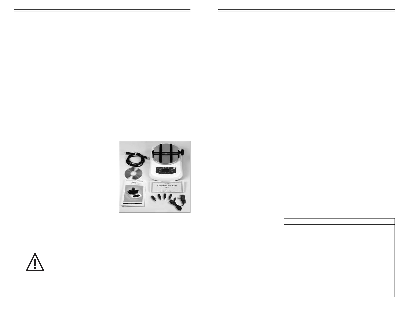
1.1 Complete Kit
Each package includes the following:
• Operations Manual
• Software Manual
• Software Installation Disk
(Digitorq Software)
• Warranty Cards
• USB A to USB B communication cable
• Universal AC adapter (100-240 VAC)
• Set of 30 mm chuck pins (4 pieces)
IMPORTANT: Upon receiving the unit, please check for any obvious physical
damage that may have occured during shipping. If any damage is found, please
notify your carrier immediately before shipping the unit back to Electromatic for
repairs and inspections.
Do not test products that are filled with liquid contents. The CAP-TNP
torque tester is not protected from liquid spills that may come from the
tested product.
- 15-
5.0 SPECIFICATIONS
OverloadProtection 150%
Sample Diameter Range (min to max) 0.39" to 7.48" (10–190 mm)
Overload display Display "OVR" on LCD (blinking on/off)
Main display 4-digit LCD display Character height 12mm
Sub display 3-digit LCD display Character height 7mm
Comparator display Hi, GO, Lo LED Indicators
Accuracy ± 0.5% full scale
Open mode Max vale when opening.
Displays max counter clockwise torque.
Close mode Max value when closing.
Displays max clockwise torque
Average mode Real time display. Displays max torque in real time
Display Update 1, 2, 4 or 8 updates/second, user-set
Sampling Rate 1000 times/second
Memory Storage 1000 data points (max)
Statistic process Average value, max value and min value
Data output USB 1.1
PC software Digitorque software
Power Built in nickle hydride battery or Auto-ranging AC
adapter (AC 100 — 240V)
Dimensions 12.60" x 8.94" x 4.96" (320 x 227 x 126mm) L x W x H
Operation Temp. 32 - 104°F (0 - 40°C)
Battery Life 8 hours after full charge
Battery Recharge Time Max. 16 hours
Battery Type NiMH
CAP-TNP-2 0-2.000 Nm
0-200.0 Ncm
0-20.39 Kgcm
0-17.70 Lbin
CAP-TNP-5 0-5.000 Nm
0-500.0 Ncm
0-50.99 Kgcm
0-44.25 Lbin
CAP-TNP-10 0-10.00 Nm
0-1000 Ncm
0-102.0 Kgcm
0-88.50 Lbin
Model Capacity Resolution
0.001 Nm
0.1 Ncm
0.01 Kgcm
0.01 Lbin
0.001 Nm
0.1 Ncm
0.01 Kgcm
0.01 Lbin
0.01 Nm
1 Ncm
0.1 Kgcm
0.1 Lbin
Torque Ranges
WARNING
Page 3
- 3 -
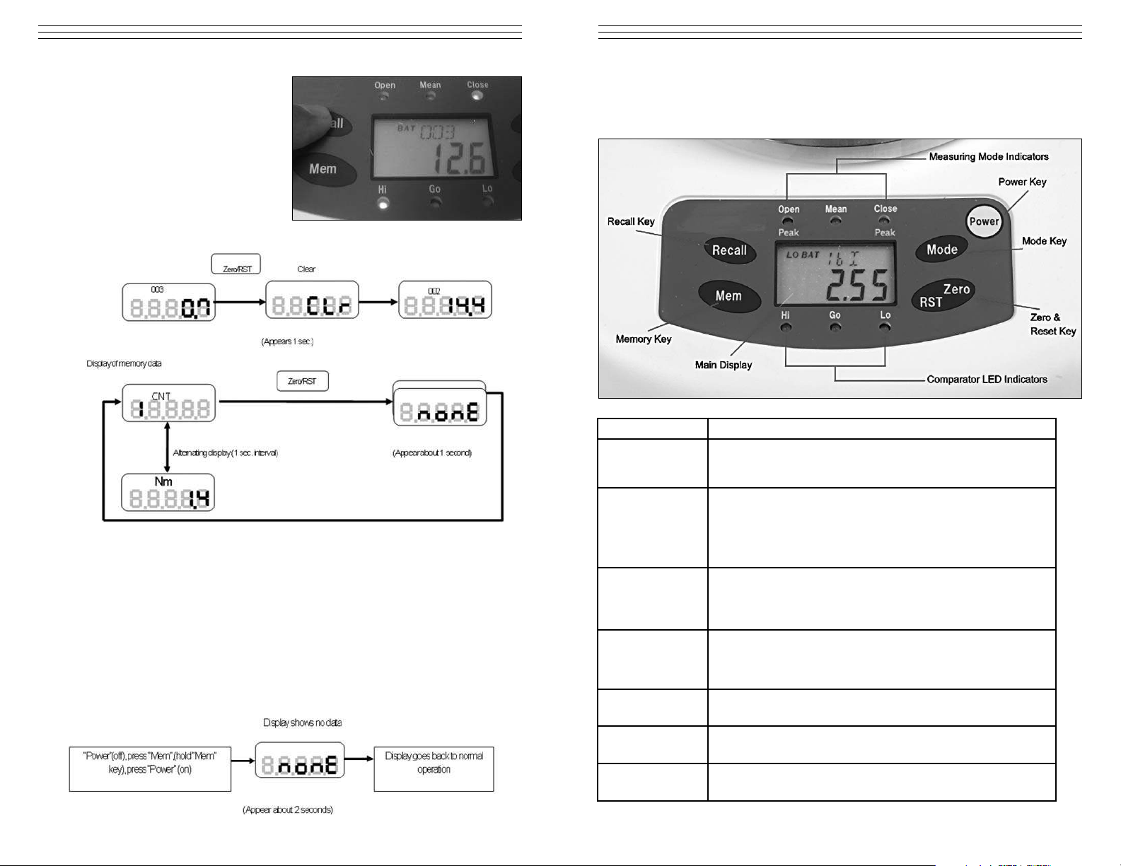
2.0 OVERVIEW
2.1 Key functions
Power key
Turns the gauge ON and OFF.
Recall key
Recall data stored in OPEN and CLOSe modes.
NOTE: in AVERAGE or MEAN mode the RECALL key has no
function.
Mem key
Memory key for storing data in OPEN and 7 Modes.
Note: In MEAN mode the Mem key has no function. In this mode
data cannot be stored in memory.
Mem combined with another key used is used in secondary
functions. (Parameter and clear settings).
Mode key
Selects mode of operation (CLOSE, MEAN, and OPEN).
Serves as an exit function when in Memory recall.
Secondary function in parameter settings (see section 3.0, page 5)
Zero/RST key
Tare or zero function for resetting and initializing values while in
Average or peak mode.
Secondary function in parameter settings (see section 3.0, page 5)
Main Display
Displays measured values and status indicators, which includes
units of measure, battery status, function status.
Measuring mode
indicators
Red LED mode indicators. Informs which mode is selected
OPEN, MEAN or CLOSE .
Comparator LED
indicators
Quick pass/fail visual indicators for all modes of measurement.
The LED indicator does not light when comparator feature is OFF.
- 14 -
Example: The picture at right shows
3 data is saved (003) and the last
value is 12.6. Pressing the
Zero/RST key eliminates the last
data (CLr will appear on the
screen). Pressing the Zero/RST
keyagain deletes the next data
stored in the memory.
Shown on the below is a diagram illustrating how the single clear works.
After all the data are erased, pressing the Zero/RST key returns the display to
normal measuring condition.
Clear All Procedure
Clear all or erasing all stored data in memory is possible by doing the following.
1. Power off the TNP torque mete.r
2. Press the MEM key and continue to hold this key while turning on the power.
The CAP-TNP will initialize itself. You will see the model capacity displayed
on the front panel then followed by the message nonE. This indicates that all
data stored in memory are cleared.
Page 4

- 4 -
2.2 Main Display
Units/Status indicator – located on the upper part of the display, this
shows the current units of measure selected for the torque meter. It also
serves a function sub-display under the function mode (F01, F02, F03, etc.)
• OVR: indicates an overload condition, meaning the CAP-TNP went over its
rated capacity.
• PWR: when the auto power off feature is set from the torque meter this
indicator serves as a 1 minute warning before the unit turns off.
Main display/Set up Values – shows the measured value in four digits
including decimal places. Under the function mode it displays the options
for each setting.
Direction Indicator – indicates direction of applied torque based upon the F04
setting (Please see sign orientation information from function mode table,
section 3.1). By default a negitive sign (–) indicates closing; no sign indicates
opening.
Battery Indicator – shows the status of the internal battery of the CAP-TNP.
LO BAT appears on the display to indicate a low battery status. BAT is shown
when the TNP is charging. This indicator disappears when the battery is at full
charge or the AC adapter is disconnected from the CAP-TNP.
NOTE: It is important that the battery be cycled properly to achieve the
maximum battery life.
- 13 -
4.9 Clearing Stored Data
There are two types of clear available on the CAP-TNP torque meter.
• Single Clear
• Clear All
Single Clear Procedure
Single clear refers to erasing the stored data manually from the torque tester. The
erase process starts from the most recent to the very earliest data stored.
NOTE: Clearing data that is within the set cannot be accomplished by single
clear. The CAP-TNP does not allow the user to select the memory to be deleted.
1. Select from the OPEN or CLOSE modes (Mean or Average mode data cannot
be stored).
2. Press the RECALL key to access memory, the first display that you will see
will indicate the number of data stored in the torque tester and the last value
saved.
Page 5

- 5 -
3.0 ACCESSING SECONDARY FUNCTIONS
Operation Key Operation
How To Operate
Zero/RST
Power
Function Mode
1. With Power off, press and hold the
Zero/RST key, then turn the power on.
2. Continue holding the Zero/RST key
until the display shows F01.
3. Pressing the Mode key changes the
value of the selected function mode.
Pressing the Zero/RST key advances from
one parameter to the next The list of
function are provided in the next section.
(See picture above).
Function Mode Clear Memory Date
1. With Power off, press and hold the
Mem key, then turn the power on.
2. Continue holding the Mem key until
nonE appears on the display.
This photo indicates the torque meter is in Function Mode.
IMPORTANT: If the display indicates normal operation of the torque meter, but
F01 is not seen on the display, the Zero/RST key was released
too soon. Turn off the torque meter and repeat the process.
- 12-
3. Press Recall key second time to
access the following information.
• Max
• Min
• Average
• Stored data (Order of data
recall is based from the last
data stored in memory)
To access the stored measured value
use the RECALL key to scroll thru the
values. (This will be after the MIN
value is displayed). The display will flash two sets of numbers, the first number
indicates the memory ID and the second number is the value stored on that
memory ID.
NOTE: The order of values is from the last data stored to the first data stored.
To review previous values shown, scroll thru the values using
the RECALL key.
Displays Max, Min and Average Values
Picture above indicates the memory ID followed by the stored data. Pressing the
mode button any time exits out of the memory window. Shown on the next page
is a chart outlining how the Recall function works.
Page 6

- 6 -
3.1 Function Mode Table
FUNCTION
Sub
display
Options Initial Setting
Measuring Unit F01
Changes units of measure:
N.m, N.cm, Kg.cm, Lb.in
N.m
Function Mode
F02
Switch 1, 2, 4, 8
times/second
2
Display (update rate) F03 10 minutes or so 10 minutes
Auto power OFF F04
–0000 CCW (Open“–”); 0000
CW (Close “+”)
0000
Upper comparator
value (Hi Limit)
HI
0000 – 9999: with
decimal point. (Setting
the values to zero
disables this function)
0000
Lower comparator
value (Lo Limit)
LO
0000 – 9999: with
decimal point (Setting the
values to zero disables
this function).
0000
3.2 How to change the value on the function selected
To change the values of the function selected press the MODE key to scroll thru
the options and the Zero/RST button to move to the next Mode.
NOTE: Pressing the MODE key after the HI/LO limits exits out of the function
mode. You will need to reenter the settings to change additional values.
3.3 Moving through the Function Modes
1. Make sure the that gauge is turned off.
2. Press and hold the Zero/RST key.
3. Press and release the power key, but continue to hold the Zero/RST key.
NOTE: Use the MODE key to changes values of each function. Use the
Zero/RST key to move to the next function.
- 11 -
4.6 Zero adjustment (Tare)
Taring or zeroing the value of the CAP-TNP initializes the torque meter to zero.
This function is performed by simply pressing Zero/RST button from the front
panel. In OPEN and CLOSE modes this zeros out the Peak values measured.
It is essential and recommended that the CAP-TNP be zeroed out before
performing another test. This ensures that the gauge is properly initialized and
no additional values are added to the measurement.
4.7 Saving Data in Memory
Data can be stored in the CAP-TNP by pressing the MEM key. This feature is
only available in OPEN and CLOSE measuring modes. In AVERAGE mode the
MEM key has no function.
4.8 How to recall stored memory
1. Select OPEN or CLOSE Mode,
2 Press the RECALL key and the
display will indicate the number
of data stored in memory.
Take a closer look at the display. The
upper sub-display indicates the memory
identification number.
Page 7

- 7 -
NOTE: Use the MODE key to changes values of each function. Use the
Zero/RST key to move to the next function.
- 10 -
4. Press the Zero/RST key until the main
display shows HI limit.
5. Use the RECALL key to set the highlighted
digit from 0-9.
6. Press the MEM key to move from left to
right or to the next digit.
7. If iinvalid values are entered, the display
will blink momentarily indicating wrong
values entered to the HI and LO limits.
(HI>LO, HI=LO).
8. After entering the LO limit value and pressing
the Zero/RST button the torque tester will go back to normal operation.
The chart below shows how the Comparator values are changed and accessed
from the Function mode settings after F04.
Page 8

- 8 -
4.0 OPERATION
4.1 Preparing for testing
1. Determine the size of the sample to be tested.
Adjust the 4-pin jig on the testing table
accordingly.
2. Center the sample and use the knob to secure
the sample in place (turn clockwise to tighten
the jig to the sample material),
NOTE: It is important to make sure that all the
jigs are flush against the moving brackets. Each
jig has set pins which slide into place inside the
grooved brackets.
4.2 Changing Units of Measure
1. Press and hold the Zero/RST key.
The display will appear as shown at right.
2. While still pressing the Zero/RST key, press
and release the POWER key. The display
will change as shown at right.
3. Release the Zero/RST key. The display
will change again as shown at right.
4. Press MODE to change the measuring unit.
The sequence is as follows: N–m N– cm Kg–Cm Lb –in
5. Press the POWER key to exit.
4.3 Selecting the Measuring Mode
1. Measuring modes available on the CAP-TNP are OPEN, CLOSE, and MEAN.
Pressing the MODE Key toggles through the modes available. Red LEDs
indicate the mode selected. See diagram below.
NOTE: OPEN and CLOSE modes are PEAK Values captured by the CAP-TNP,
these values are not real-time values and are retained on the display until the
Zero/RST key is pressed or a higher peak value is detected (which in this case
replaces the current value detected). MEAN is the real-time value based on the
average data captured at 1000 samples per second.
- 9 -
NOTE: The maximum display update for all modes is 8 times/second. This
update rate can be adjusted by changing F02 from function mode (section 3.2)
Values available are 1, 2, 4, 8 times/second.
4.4 Comparator Function
This function compares the upper and lower limit based upon the values entered
under function mode for HI and LO limits (section 4.4).
If both HI and LO limits are set to “0000” this feature is not available. The
following conditions are valid under comparator mode:
• HI>LO
• HI=LO (HI Red LED indicator will be lit on the Comparator LED indicators).
This feature makes the CAP-TNP an ideal tool for quality assurance checking.
Example: HI is set to 100 and LO is set to 50. Based from the conditions
met the corresponding LED will light up — HI (Red LED), GO (Green LED),
LO (Red LED).
From the previous example any values greater than 100 will light up the
HI red LED.
Any values lower than 50 will light up the LO red LED.
Values measured in between these values (100<X<50) will give a GO green
LED indicator.
4.5 Setting the HI and LO values
To set the HI and LO limits from the TNP torque meter we need to access the
function mode.
1. Turn off the torque meter.
2. Press and hold the Zero/RST key then turn on the power.
3. Continue to hold on the Zero/RST key until the main display shows F01.
Resetting the Peak Values to zero.
Page 9

7.0 WARRANTY
ELECTROMATIC Equip’t Co., Inc. expressly warrants to its buyer for three (3) years
from the date of delivery that the goods sold are free from defects in workmanship and
materials. ELECTROMATIC Equip’t Co., Inc. will, at its option, repair or replace or
refund the purchase price of goods found to be defective. This remedy shall be the
buyer’s sole and exclusive remedy. Any modification, abuse, exposure to corrosive
environment or use other than intended will void this warranty. This warranty is in lieu
of all other warranties, including implied warranties of merchantability and fitness for
an intended purpose. In no event shall ELECTROMATIC Equip’t Co., Inc. be liable
for any incidental and consequential damages in connection with goods sold or any
part thereof.
Page 10

CAP-TNP
DIGITAL CAP TORQUE TESTER
Operating Instructions
CHECK•LINE
®
BY ELECTROMATIC
ELECTROMATIC
E Q U I P M E N T C O., I N C.
600 Oakland Ave., Cedarhurst, NY 11516–U.S.A.
TEL: 516-295-4300 • FAX: 516-295-4399
CHECK•LINE
®
INSTRUMENTS
 Loading...