

Page 1
User’s Guide
CAP-TA
CAP TORQUE TESTER
User’s Guide
Page 2

CAP-TA Cap Torque Testers
Page 3

User’s Guide
Thank you!
Thank you for purchasing a CAP-TA Cap Torque Tester. We are
confident that you will get many years of service from this product.
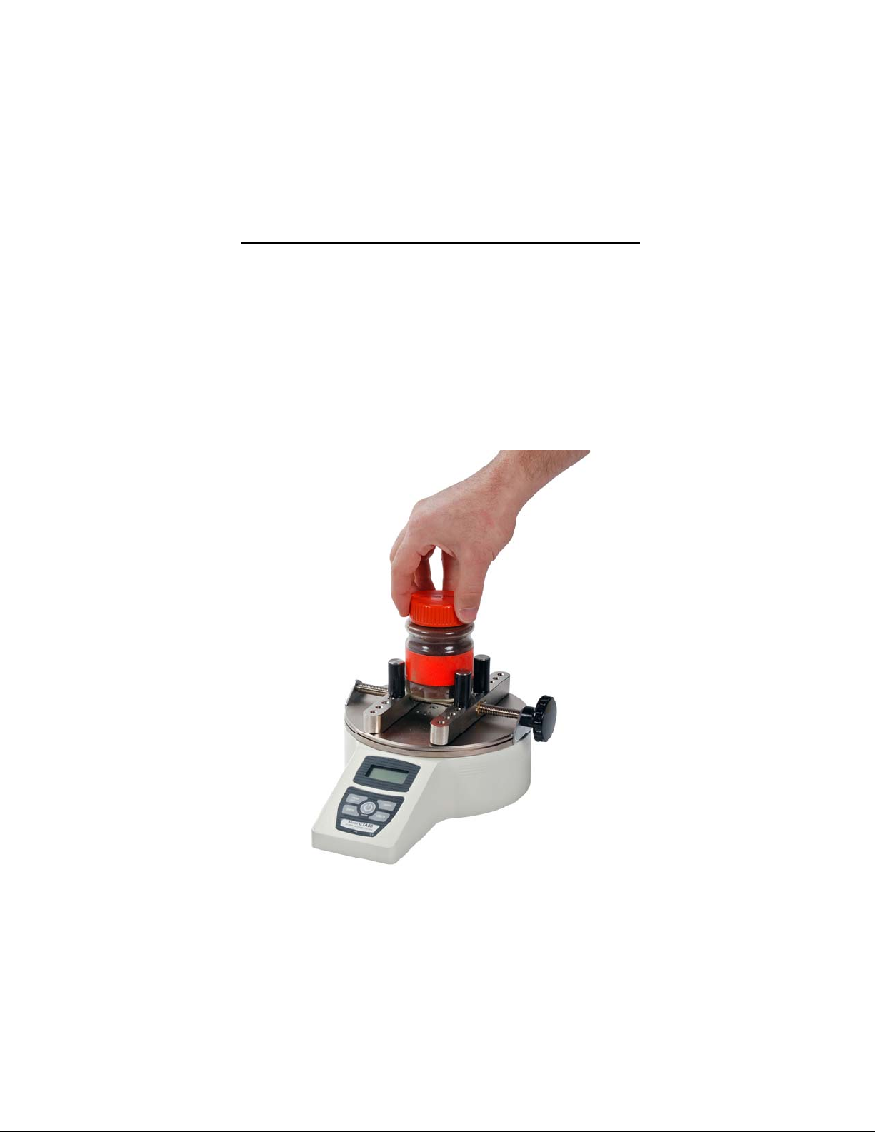
The CAP-TA can be used to test cap torque for a number of different closure shapes and sizes, along with other types of samples. To maintain normal functioning of the tester, avoid repetitive overloads and shock loads.
We hope that this User’s Guide will provide a comprehensive
explanation of the CAP-TAs operation and sufficient detail on its
specifications. However, if you have any other questions or concerns, our technical support and engineering teams will be eager to help you.
Thank you again for your purchase and happy testing!
TABLE OF CONTENTS
UNPACKING AND SETTING UP ............................................... 2
LIST OF INCLUDED ITEMS ....................................................... 2
CONTROLS ................................................................................ 3
DISPLAY ..................................................................................... 3
POWER ....................................................................................... 4
SETTING UP THE SAMPLE....................................................... 4
CONFIGURATION ...................................................................... 5
CALIBRATION ............................................................................ 6
OUTPUTS ................................................................................... 7
SPECIFICATIONS ...................................................................... 8
DIMENSIONS .............................................................................. 9
WARRANTY ............................................................................... 9
1
Page 4
CAP-TA Cap Torque Testers
UNPACKING AND SETTING UP
1. Carefully unpack the CAP-TA and check for any damage. Inspect the contents to ensure that you have received a tester complete with all accessories
– see “List of included items” below.
2. Place the tester on a firm, flat and level working surface free from vibration. If
preferred, the CAP-TA can be secured to a work bench with screws through
the four tapped holes in the underside of the base. Then fasten the sample
gripping posts into the desired holes on the sliders (see Fig. 1).
LIST OF INCLUDED ITEMS
Quantity Item
1 CAP-TA Torque Tester
1 User’s guide (this booklet)
4 Sample gripping posts
2 Sample gripping jaws (optional, see below)
1 Carrying case (optional)
1 AC adapter
1 Battery
1 Certificate of calibration
CT001 flat jaws (optional)
These jaws are designed for use with square or
other shaped containers, in addition to round samples. The jaws are reversible; one side has a Vgroove, while the other side is flat. These jaws can
be mounted to the inside of the sliders, or the outside.
CT003 adjustable jaws (optional)
These jaws are designed for use with unique
shaped samples. The four gripping arms per jaw
may be independently repositioned in 45° increments to accommodate unique profiles. Loosen the
screw at the top of the jaw to separate the arms
and reposition as desired.
2
Page 5

User’s Guide
CONTROLS
POWER / ENTER
Turns power on and off. Also used to select configuration menu items.
PEAK / ADVA NCE
Used to switch between Clockwise Peak,
Counterclockwise Peak and Normal (real
time) display modes. The actual peak
readings are always captured and can be
recalled at any time by pressing this button. Also used to step through configuration menu items.
ZERO
Zeros any tare value (up to the full capacity of the gauge) and clears the peak readings stored in memory.
DATA
Used to output the torque data point currently displayed.
UNITS
Changes measurement units between lbin, Ncm, and kgmm.
DISPLAY
The display consists of a 4 1/2-digit section and several indicators. Their functions are listed below.
LO BAT Low battery voltage indicator
CW Clockwise torque indicator
CCW Counterclockwise torque indicator
CW PEAK Peak clockwise torque indicator
CCW PEAK Peak counterclockwise torque indicator
LBIN, NCM, KGMM Units of measurement
- - - - (dashes) Overload (>110% of range)
Reduce torque immediately
3
Page 6

CAP-TA Cap Torque Testers
POWER
The CAP-TA can be operated by the included 9V non-rechargeable battery or by
the included AC adapter. Battery life is approximately 30 hours.
Do not use adapters other than supplied or instrument damage may occur.
There are three levels of low battery voltage indication. At the first level the dis-
play shows a steady "LO BAT" indicating approximately one hour of charge remaining. The second level is indicated by a flashing "LO BAT" indicator. At the
third level the whole display except the "LO BAT" indicator will flash for three
seconds after which time the instrument will turn itself off. This prevents the instrument from working at voltages too low for reliable operation.
To access the battery, loosen the four screws on the bottom plate.
SETTING UP THE SAMPLE
Place the sample between the posts or jaws of the tester, and tighten, using the
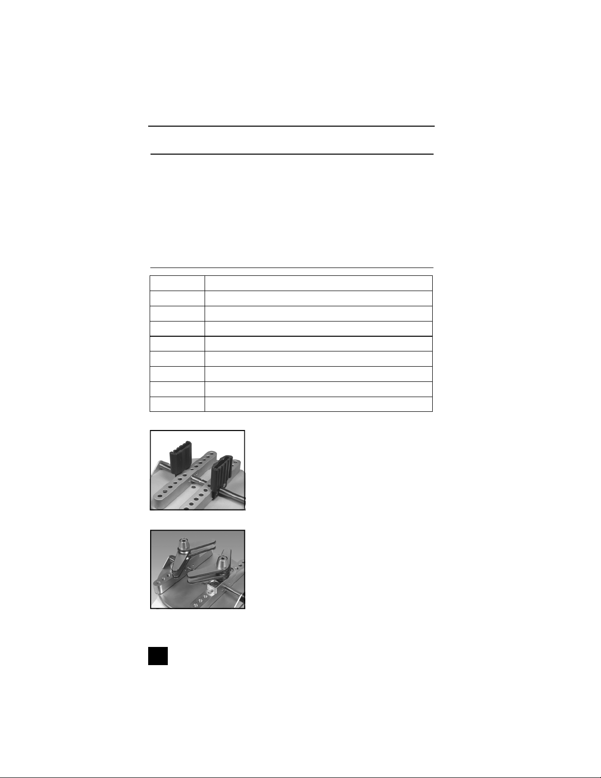
knob. Posts can be placed in any of the holes on the sliders (see Figs. 1 & 2
below). Ensure that the sample is gripped firmly, however, excessive tightening
of thin-walled closures may result in sample deformation, possibly affecting test
results. When the sample is secured, gradually exert torque by hand. Sudden
torque application may produce incorrect readings.
Fig. 1
Posts can easily be moved
between holes
4
Fig. 2
Optional jaws offer alternative
gripping methods
Page 7

User’s Guide
CONFIGURATION
CAP-TA torque testers have several features with programmable options allowing many user-specified choices. To enter the configuration menu, perform the
following:
1. Turn off the tester
2. Press and hold PEAK
3. Turn on the tester
4. Release PEAK
The version number of the internal software will be displayed for a short time.
The following secondary functions of keys are used during the configuration
process:
ENTER Used to select a menu choice
ADVANCE Used to step through menu choices
NOTE: Once the menu has been entered, it can only be exited if changes have
been made.
The following list shows all configuration options. Italics indicate factory set-
tings.
232 - RS-232 settings sub-menu
232d Output Disabled
232E Output Enabled
300 300 baud
600 600 baud
1200 1200 baud
2400 2400 baud
4800 4800 baud
9600 9600 baud
7-1E 7 data bits, 1 stop bit, even parity
7-1o 7 data bits, 1 stop bit, odd parity
7-2E 7 data bits, 2 stop bits, even parity
7-2o 7 data bits, 2 stop bits, odd parity
7-2n 7 data bits, 2 stop bits, no parity
8-1E 8 data bits, 1 stop bit, even parity
8-1o 8 data bits, 1 stop bit, odd parity
8-1n 8 data bits, 1 stop bit, no parity
8-2n 8 data bits, 2 stop bits, no parity
Ft F Full data (numeric + units)
Ft n Numeric data only
bcd - Mitutoyo BCD settings sub-menu
bcdd Output disabled
bcdE Output enabled
nPOL No polarity (absolute value)
POL Data with polarity (+ for CW, - for CCW)
5
Page 8

CAP-TA Cap Torque Testers
AoFF - Automatic shutoff settings sub-menu
no Disabled
1 1-minute automatic shutoff
5 5-minute " “
10 10-minute “ “
20 20-minute " "
30 30-minute " "
init - Initial (default) settings sub-menu
LBIN Pound-inch as default unit
KGMM Kilogram-millimeter as default unit
NCM Newton-centimeter as default unit
CCW Real time display at turn on
PEAK CW Peak clockwise display at turn on
PEAK CCW Peak counterclockwise display at turn on
CAL - Calibration sub-menu. See CALIBRATION section.
CALIBRATION
To properly calibrate the CAP-TA, application of a precise torque value equal to
the full capacity of the tester in pound-inches (regardless of the displayed units)
is required.
While holding PEAK, turn on power to the tester. When ‘CAL’ appears on the
display, press ENTER three times to select the calibration mode. At the ‘null’
prompt, press ZERO. At the ‘SPAn’ prompt, apply the calibration torque and
press ENTER. The display will show ‘uuuu’ or ‘nnnn’ if the calibration torque is
insufficient or excessive, respectively. If this happens, the only way to terminate
the calibration mode is by momentarily disconnecting the battery or connecting
the AC adapter to the tester without plugging the other end into a wall outlet.
This will stop the calibration procedure without making any changes to the previous calibration data.
Successful calibration is indicated by ‘donE’ on the display. Press ENTER to
save the changes and resume normal operation.
6
Page 9

User’s Guide
OUTPUTS
RS-232
Data transmission can be initiated by pressing DATA or through an external
device by sending ASCII "?". The tester will respond by sending the current reading in either full or numeric format, depending on the configuration setting (see
Configuration section). Polarity sign indicates CW (+) or CCW (-) torque. The
transmitted string has the following format:
[POLARITY (SPACE OR -)][DATA][SPACE][UNITS (IF ENABLED)][CRLF]
Mitutoyo BCD
This output is useful for connection to data collectors, printers, multiplexers or
any other device capable of accepting Mitutoyo BCD data. The transmission is
initiated by pressing DATA or by the receiving device.
I/O connector pin diagram
1 RS-232 receive Input
1298345
7
6
DB-9P
2 RS-232 transmit Output
3 Mitutoyo request Input
4 Mitutoyo clock Output
5 Signal ground 6 No connection
7 No connection
8 Mitutoyo ready Output
9 Mitutoyo data Output
7
Page 10

CAP-TA Cap Torque Testers
SPECIFICATIONS
Accuracy: ±0.5% of full scale ±1digit
Sampling rate: 65/s
Display update rate: 2.5/s in normal mode, 65/s in peak mode
Safe overload:
Outputs (optional):
RS-232: Baud rates between 300 and 9600
Mitutoyo: Standard Mitutoyo BCD output
Connector: 9-pin D-type male
Power: 9V battery or AC adapter
Battery life: 30 hours of continuous operation
Weight: 6.5 lb [2.9 kg]
Capacity x resolution:
CAP-TA-12 12 x 0.01 lbFin, 140 x 0.1 kgFmm, 135 x 0.1 Ncm
CAP-TA-50 50 x 0.05 lbFin, 580 x 0.5 kgFmm, 570 x 0.5 Ncm
CAP-TA-100 100 x 0.1 lbFin, 1150 x 1 kgFmm, 1150 x 1 Ncm
150% of gauge capacity. Display shows
---- (dashes) above 110%.
8
Page 11

User’s Guide
DIMENSIONS in [mm]
WITH OPTIONAL
7.8 [199.3]
10.7 [270.5]
Ø7.5 [189.4] MAX
Ø0.5 [12.7] MIN
4.8 [121.8]
1.3 [33.0]
FLAT JAWS:
5.9 [149.9] MAX
1.3 [33.0] MIN
4.4 [111.8] MAX
0 MIN
Ø6.0 [151.9] MAX
Ø1.3 [33.0] MIN
Ø4.4 [111.8] MAX
Ø0.25 [6.35] MIN
WITH OPTIONAL
ADJUSTABLE JAWS:
Ø4.6 [116.8] MAX
Ø0 MIN
WARRANTY
EEC Corporation expressly warrants to its buyer for three (3) years from the date
of delivery that the goods sold are free from defects in workmanship and materials. EEC Corporation will, at its option, repair or replace or refund the purchase
price of goods found to be defective. This remedy shall be the buyer’s sole and
exclusive remedy. Any modification, abuse, exposure to corrosive environment
or use other than intended will void this warranty. This warranty is in lieu of all
other warranties, including implied warranties of merchantability and fitness for
an intended purpose. In no event shall EEC Corporation be liable for any incidental and consequential damages in connection with goods sold or any part
thereof.
9
Page 12

CAP-TA Cap Torque Testers
ELECTROMATIC Equip’t Co., Inc
600 Oakland Ave.
Cedarhurst, NY 11516
Tel: 800-645-4330 / 516-295-4300
Fax: 516-295-4399
Email: info@checkline.com
Website: www.checkline.com
 Loading...