

Page 1

- 1 -
01.0 Introduction . . . . . . . . . . . . . . . . . . . . . . . . . . . . . . . . . . . . . . . . . . . . 02
1.1 Included Items
1.2 Optional Items
02.0 Set-Up . . . . . . . . . . . . . . . . . . . . . . . . . . . . . . . . . . . . . . . . . . . . . . . 03
03.0 Controls . . . . . . . . . . . . . . . . . . . . . . . . . . . . . . . . . . . . . . . . . . . . . . .003
04.0 Display . . . . . . . . . . . . . . . . . . . . . . . . . . . . . . . . . . . . . . . . . . . . . . .004
05.0 Power . . . . . . . . . . . . . . . . . . . . . . . . . . . . . . . . . . . . . . . . . . . . . . .004
06.0 Changing Units Of Measure . . . . . . . . . . . . . . . . . . . . . . . . . . . . . . . 05
07.0 Configuration . . . . . . . . . . . . . . . . . . . . . . . . . . . . . . . . . . . . . . . . . . . 05
7.1 232 - RS-232 settings sub-menu
7.2 bcd - Mitutoyo BCD settings sub-menu
7.3 AoFF - Automatic shutoff settings sub-menu
7.4 init - Initial (default) settings sub-menu
08.0 Calibration . . . . . . . . . . . . . . . . . . . . . . . . . . . . . . . . . . . . . . . . . . . . . 07
09.0 Operation . . . . . . . . . . . . . . . . . . . . . . . . . . . . . . . . . . . . . . . . . . . . . . 08
9.1 Changing operating modes & measuring units
9.2 Modifying Auto-Shutoff
10.0 Specifications . . . . . . . . . . . . . . . . . . . . . . . . . . . . . . . . . . . . . . . . . . . 09
10.1 Force Ranges
10.2 Dimensional Drawings
11.0 Outputs . . . . . . . . . . . . . . . . . . . . . . . . . . . . . . . . . . . . . . . . . . . . . . . 11
12.0 Warranty . . . . . . . . . . . . . . . . . . . . . . . . . . . . . . . . . . . . . . . . . . . . . . . 12
CONTENTS
- 12 -
12.0 WARRANTY
ELECTROMATIC Equip’t Co., Inc. expressly warrants to its buyer for
three (3) years from the date of delivery that the goods sold are free from
defects in workmanship and materials. ELECTROMATIC Equip’t Co., Inc.
will, at its option, repair or replace or refund the purchase price of goods
found to be defective. This remedy shall be the buyer’s sole and exclusive
remedy. Any modification, abuse, exposure to corrosive environment or use
other than intended will void this warranty. This warranty is in lieu of all other
warranties, including implied warranties of merchantability and fitness for an
intended purpose. In no event shall ELECTROMATIC Equip’t Co., Inc. be liable
for any incidental and consequential damages in connection with goods sold or
any part thereof.
Page 2
- 2 -
1.0 INTRODUCTION
Thank you for purchasing a Check-Line CAP-T Torque Tester. We are confident
that you will get many years of service from this product.
The CAP-T can be used to test a number of different closure shapes and sizes,
along with other types of samples. To maintain normal functioning of the tester,
avoid repetitive overloads and shock loads.
Two models are available. The CAP-T-XX basic model and the CAP-T-XXRS
which includes an RS-232 and Digimatic output for connection to a PC or printer.
Before continuing, carefully unpack the CAP-T and check for any damage.
Inspect the contents to ensure that you have received a tester complete
with all accessories.
1.1 Included items
• CAP-T Torque Tester
• User’s guide (this booklet)
• 4 Sample gripping posts
• AC Adapter
1.2 Optional Items
• Sample Gripping Jaws:
See photo page 3. These jaws are
for use with square or or other
shaped containers, in addition to
round samples. The jaws are
reversible; one side has a V-groove,
while the other side is flat. These jaws
can be mounted to the inside or outside
of the sliders. Part # CAP-T-JAWS
• CAP-T-XX RS Version:
This model allows torque data to be transferred
to a PC, printer, or other device for data analysis.
The package consists of a serial connector and
data button to manually output data. For more
automated data collection, common software
programs such as WinWedge (available from
Electromatic) can be configured to automatically
request data from the CAP-T.
Gripping
Post
- 11 -
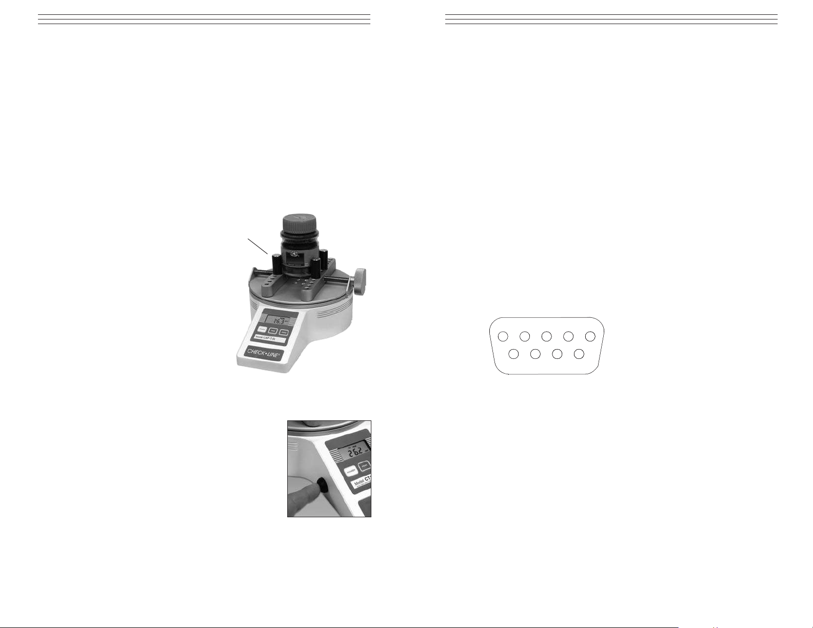
11.0 OUTPUTS
Outputs are available as part of the CTRS communication option. If installed, it
offers RS-232 and Mitutoyo BCD outputs on the 9-pin male connector. Please
refer to the pin diagram below for proper connection.
RS-232
The data transmission can be initiated by pressing the DATA button or by an
external device by sending ASCII "?" to the gauge. The gauge will respond by
sending the current reading in either full or numeric format, depending on the
configuration setting (see Section 3). Polarity sign indicates CW (+) or CCW (-)
torque. The transmitted string has the following format:
[POLARITY (SPACE OR -)][DATA][SPACE][UNITS (IF ENABLED)][CRLF]
Mitutoyo BCD
This output is useful for connection to data collectors, printers, multiplexers or
any other device capable of accepting Mitutoyo BCD data. The transmission is
initiated by the DATA button (see Section 3 about settings) or by the receiving
device.
1 RS-232 receive Input
2 RS-232 transmit Output
3 Mitutoyo request Input
4 Mitutoyo clock Output
5 Signal ground
6 No connection
7 No connection
8 Mitutoyo ready Output
9 Mitutoyo data Output
21
543
7
6
98
P9-BD
Page 3

- 3 -
2.0 SET-UP
Carefully unpack the CAP-T and check for
any damage. Inspect the contents to ensure that
you have received a tester complete with all
accessories – see page 2.
Place the tester on a firm, flat and level
working surface free from vibration. If
preferred, the CAP-T can be secured to a
work bench with screws through the four
tapped holes in the underside of the base.
Then insert the posts or sample gripping jaws
into the desired holes on the sliders.
3.0 C
ONTROLS
CAP-T Torque Testers have three
keys for controlling all functions:
POWER: Turns power on and off.
Also used in Calibration mode.
PEAK: Used to select Clockwise
Peak, Counterclockwise Peak or
Normal (real time) display mode.
The actual peak readings are always
captured and can be recalled at any
time.
ZERO: Zeros any tare value (up to
the full capacity of the gauge) and
clears the peak readings stored in
memory.
DATA: (optional) Used to manually
output the torque data point currently
displayed.
Gripping jaws
(optional)
Part # CAP-T-JAWS
Gripping posts (included)
- 10 -
10.2 Dimensional Drawings
all dimension in mm
[ 8.7
]3.991
10.7 [270.5]
T
P
IW
O
H
NOI
T
5
.941[ 9
.
3.1
]0.33[
4
]8.111[ 4.
NIM 0
:SWAJ
LA
XAM ]9
IM
N
X
AM
XAM ]4.981[ 5.7Ø
NIM ]7.21[ 5.0Ø
3.1Ø
XAM ]9.151[ 0.6Ø
NIM ]0.33[
XAM ]8.111[ 4.4Ø
NIM ]53.6[ 52.0Ø
4.8 [121.8]
1.3 [33.0]
Page 4

- 4 -
4.0 DISPLAY
The display consists of a 4-1/2 digit
section and several indicators. Their
functions are listed below.
LO BAT Low battery voltage
indicator
CW Clockwise torque indicator
CCW Counterclockwise torque indicator
CW PEAK Peak clockwise indicator
CCW PEAK Peak counterclockwise indicator
OZIN, LBIN
NCM, KGMM Units of measurement (model dependent)
- - - - (dashes) Overload (>110% of range)
5.0 P
OWER
The CAP-T may be powered by the internal 9V battery, or by the included
AC adapter. The need for battery replacement is indicated by a 3-step sequence:
1. A steady LO BAT appears on the display indicating the last 10% of
battery life
2. LO BAT begins to flash indicating the need for an immediate battery
replacement
3. The entire display except LO BAT flashes for several seconds and then
the tester shuts off.
- 9 -
10.0 SPECIFICATIONS
Accuracy ±0.5% of full scale ±1digit
Sampling rate 30/s
Display update rate 2.5/s in normal mode, 30/s in peak mode
Safe overload 150% of gauge capacity.
Display shows---- (dashes) above 110%.
Power 9V battery or AC adapter
Battery life 30 hours of continuous operation
Weight 10 lb [4.5 kg]
9.1 Force Ranges
Model Capacity Resolution
CAP-T-12 12 lb-in 0.01 lb-in
140 kg-mm 0.1 kg-mm
135 N-cm 0.1 N-cm
CAP-T-50 50 lb-in 0.05 lb-in
580 kg-mm 0.5 kg-mm
570 N-cm 0.5 N-cm
CAP-T-100 100 lb-in 0.1 lb-in
1150 kg-mm 1 kg-mm
1150 N-cm 1 N-cm
Page 5

- 5 -
6.0 CHANGING UNITS OF MEASURE
1. Press and Hold the PEAK key and at the same time. Press the POWER
key. (The Display will show "Aoff"). Then release all keys.
2. Press the PEAK key one (1) or more times until the display shows "init"
3. Press the POWER key one time. (The currently selected unit of measure will
flash on/off on the right side of the display)
4. Press the PEAK key to cycle thru the choices of units. Each time the PEAK
key is pressed the new units selection will be shown on the right side of the
display. (The desired unit of measure should be flashing before you continue
to step #5.)
5. Press the POWER key two (2) times to store the new units selections. Display
will show "donE".
6. Press POWER again to return to the measurement mode with the new unit
selection.
7.0 C
ONFIGURATION
CAP-T torque testers have several features with programmable options
allowing many user-specified choices. To enter the configuration menu,
perform the following:
1. Turn off the tester
2. Press and hold PEAK
3. Turn on the tester
4. Release PEAK
The version number of the internal software will be displayed for a short time
followed by either 'AoFF' for a standard CT or '232' if equipped with CTRS
communication option. The following secondary functions of keys are used
during the configuration process:
POWER Used to select a menu choice
PEAK Used to step through menu choices
7.1 232 - RS-232 settings sub-menu
232d Output Disabled
232E Output Enabled
300 300 baud
600 600 baud
1200 1200 baud
2400 2400 baud
4800 4800 baud
9600 9600 baud
- 8 -
9.0 OPERATION
Place the sample between the posts or jaws of
the tester, and tighten,using the knob. Posts can
be placed in any of the holes on the sliders.
Ensure that the sample is gripped firmly,
however, excessively tightening thin- walled
closures may result in sample deformation,
possibly affecting test results. When the sample
is secured, gradually exert torque by hand.
NOTE: Sudden torque application may produce
incorrect readings.
The default mode of operation is the
normal (real time) mode.
If the peak readings are to be observed as they occur,
then the mode of operation can be changed by pressing PEAK until the desired mode (CW PEAK or
CCW PEAK) appears on the display.
This action affects only the display. The peak
readings are captured automatically and can be
recalled by pressing PEAK. The peak readings
may be cleared from the memory by either pressing
ZERO or shutting off power
9.1 Changing Operating Modes and Measuring Units
The displayed units of measurement and the default mode of operation
(peak or normal) can be changed by entering the setup mode as described in
section 6.0, pressing POWER at the init prompt and selecting the desired
settings using the PEAK and the POWER keys.
9.2 Auto Shut-off
The CAP-T is equipped with an automatic shutdown feature and it will shut
off after approximately 30 minutes of inactivity (readings do not change by
more than ±10 counts and no keys are pressed). The entire display will flash
for 5-7 seconds as a warning of the imminent shutdown.
To change the default setting of 30 minutes, hold PEAK while turning on
the gauge. Press PEAK repeatedly until 'AOFF' appears. Press POWER to
select this function. The current setting will flash on the display. Use PEAK
to scroll through the displayed choices and POWER to select.
Knob
Page 6

- 6 -
7-1E 7 data bits, 1 stop bit, even parity
7-1o 7 data bits, 1 stop bit, odd parity
7-2E 7 data bits, 2 stop bits, even parity
7-2o 7 data bits, 2 stop bits, odd parity
7-2n 7 data bits, 2 stop bits, no parity
8-1E 8 data bits, 1 stop bit, even parity
8-1o 8 data bits, 1 stop bit, odd parity
8-1n 8 data bits, 1 stop bit, no parity
8-2n 8 data bits, 2 stop bits, no parity
Ft F Full data (numeric + units)
Ft n Numeric data only
7.2 bcd - Mitutoyo BCD settings sub-menu
bcdd Output disabled
bcdE Output enabled
nPOL No polarity (absolute value)
POL Data with polarity (+ for CW, - for CCW)
7.3 AoFF - Automatic shutoff settings sub-menu
no Disabled
1 1-minute automatic shutoff
5 5-minute automatic shutoff
10 10-minute automatic shutoff
20 20-minute automatic shutoff
30 30-minute automatic shutoff
7.4 init - Initial (default) settings sub-menu
LBIN Pound-inch as default unit
KGMM Kilogram-millimeter as default unit
NCM Newton-centimeter as default unit
CCW Real time display at turn on
PEAK CW Peak clockwise display at turn on
PEAK CCW Peak counterclockwise display at turn on
CAL Calibration sub-menu. See CALIBRATION section.
- 7 -
8.0 CALIBRATION
To properly calibrate the CAP-T, application of a precise torque value equal
to the full capacity of the tester in lbin (regardless of the displayed units) will
be required. The procedure follows:
1. Press and hold the PEAK control while turning on power to the
CAP-T tester.
2. When CAL appears on the display, press POWER three times to select
the calibration mode.
3. At the null prompt, press ZERO.
4. At the SPAn prompt, apply the calibration torque and press POWER.
The display will show uuuu or nnnn if the calibration torque is insufficient
or excessive, respectively.
If this happens, the only way to terminate the calibration mode is by
momentarily disconnecting the battery or connecting the AC adapter to the
tester without plugging the other end into a wall outlet. This will stop the
calibration procedure without making any changes to the previous calibration
data.
5. Successful calibration is indicated by donE on the display.
Press POWER to save the changes and resume normal operation.
Page 7

CAP-T
T
ORQUE TESTER
Operating Instructions
CHECK•LINE
®
BY ELECTROMATIC
ELECTROMATIC
E Q U I P M E N T C O., I N C.
600 Oakland Ave., Cedarhurst, NY 11516–U.S.A.
TEL: 516-295-4300 • FAX: 516-295-4399
CHECK•LINE
®
INSTRUMENTS
 Loading...