

Page 1

AWS-4050 Guide
CONTENTS
1
CONTENTS
CONTENTS ..................................................1
INTRODUCTION ............................................2
Description..........................................................2
System Specifications..........................................2
OPERATION.................................................. 3
Display Operation ................................................3
nction..................................................................4
Back Panel Inputs ...............................................4
Transducer Input (12-pin connector).................4
DC In ...............................................................4
RS-232............................................................4
Charging the Batteries .........................................4
RS-232 ...............................................................4
RS232 Transfer Protocol ..................................5
RS232 Datastream Format...............................5
RS232 Cable Pinouts .......................................5
PROGRAMMING & NAVIGATION.....................6
Menu Tree ........................................................7
Button Operation: ............................................7
MENU TREE: ........................................................8
1 PEAK OPTIONS MENU ...................................8
DESCRIPTION OF FUNCTIONS ......................11
Operating Mode................................................ 11
Peak............................................................. 11
1st Peak ....................................................... 11
Track ............................................................ 11
Selecting a Transducer...................................... 11
Engineering Units.............................................. 11
Full Scale.......................................................... 12
Low Limit .......................................................... 12
High Limit ......................................................... 12
SERVICE AND WARRANTY............................13
Page 2

AWS-4050 Guide
INTRODUCTION
2
INTRODUCTION
DESCRIPTION
The AWS-4050 Torque Display is designed to provide for a wide range of
torque testing applications in the smallest foot print at a very reasonable price.
Features include an LCD graphics display, built-in battery pack for remote
testing and an Intellect External port for easy expansion with our entire line of
torque and load transducers. A new menu based user interface allows for a
wide range of software configurations while keeping the tester easy to use.
SYSTEM SPECIFICATIONS
Dimensions
Power Requirements
Operating Temperature Range
Data Communications
Accuracy
Range
Lockout Combinations
Display
Units
Filter
Width: 4.25", Height: 2.5", Depth: 7.0", Weight:1.5 Lbs.
9V DC, 150 mA (120V mains adapter standard, 240v
mains adapter avaliable) or internal NiMH batteries.
0˚C to 50˚C
RS-232-C
0.5% of Indicated Reading with AWS series transducers.
Optional 0.25% of Indicated.
10% to 100%
Optional 5% to 100%
Mode, Auto Clear, Mode & Auto Clear, Engineering Units,
Mode & Engineering Units, Auto Clear & Engineering Units,
Mode & Auto Clear & Engineering Units, None (Off)
4 active digits
Optional 5 active digits
8 Selectable engineering units.
Special units available, please inquire.
Selectable Hz filter: 125, 250, 500, 1000, 1500, & 2000
Page 3
AWS-4050 Guide
OPERATION
3
OPERATION
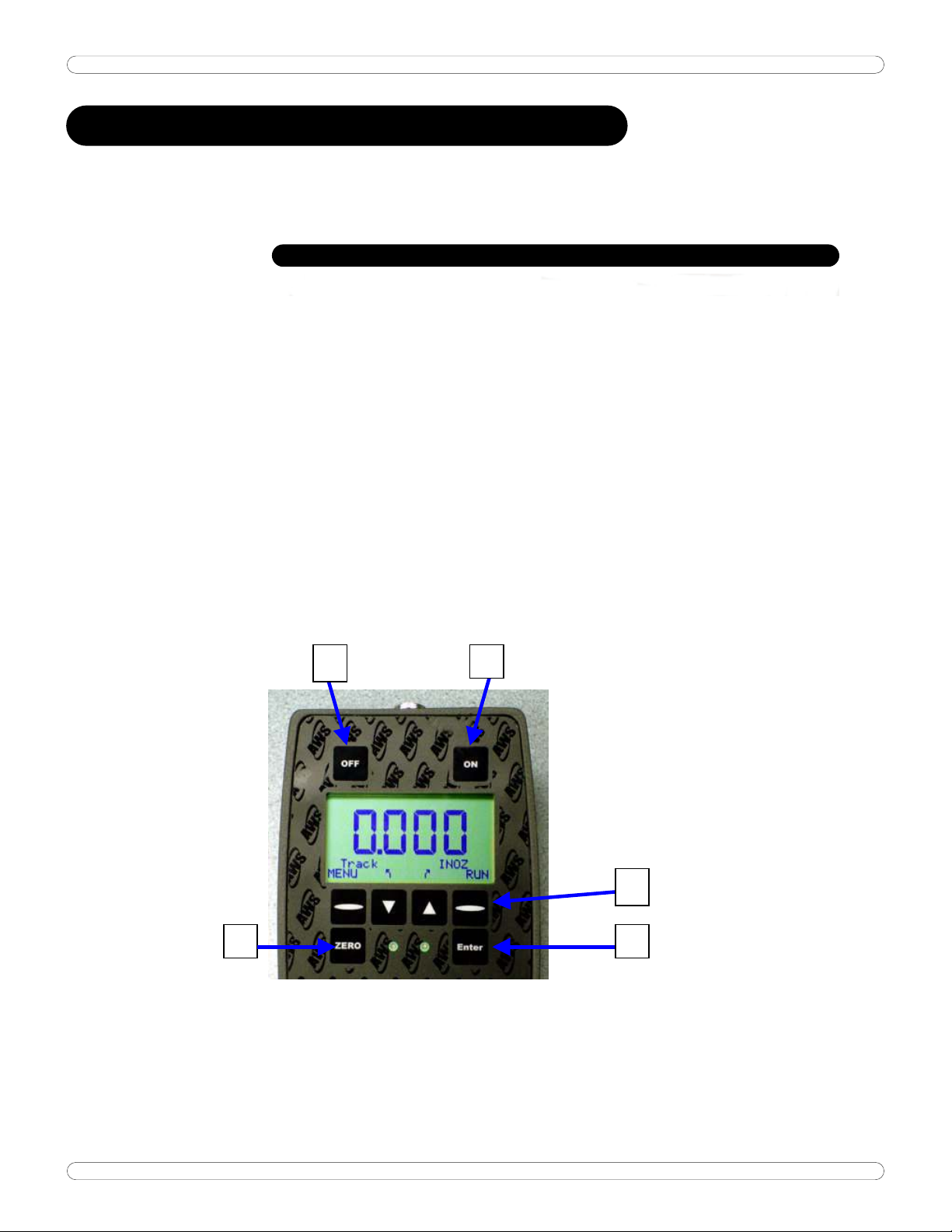
DISPLAY OPERATION
Button Function:
1: Turns the display On
Zero the Transducer
Clears the reading in Peak and 1stPeak Mode
2: Turns the display Off
3: Programmable 'Soft Buttons'. The function of these buttons vary with the
current menu set and is shown on the bottom two lines of the display.
4: Accepts the reading into memory
Scrolls back one level in the menu system
5: Zero or clear button.
2 1
3
45
Page 4

AWS-4050 Guide
OPERATION
4
NCTION
BACK PANEL INPUTS
The back of the AWS-4050 contains various interface connections:
Transducer Input (12-pin connector).
To install or remove the cable simply push in or pull out. Do this by gripping
the outer metal case of the cable and NEVER from the cord itself.
A TWIST LOCK CABLE!
DC In
The interface for the AC Adapter supplied with the unit. Use this if you plan on
working under Mains power. Use only the AC adapter provided with the unit.
Use of another power source will void the warranty and may cause severe
damage to the display.
RS-232
If you are downloading to a printer, data collector, computer, etc., this is the
mini-plug interface for the RS-232 cable. Values are sent via RS-232 every
time the unit auto-clears or the ENT/clr button is pressed
THIS IS NOT
CHARGING THE BATTERIES
1. The batteries in this system should last approximately 12 hours when fully
charged. The Low-Battery indicator on the display will illuminate when the
battery voltage is low. Typically, the user will have between 15-30
minutes before the batteries become too weak to power the unit.
2. The batteries are charged any time the system is plugged-in. In Fast
Charge mode, i.e. the unit is plugged in and the power is
is between 2 and 4 hours depending on battery charge level. The green
LED on the front panel will flash when the battery is charging and turned
off. It is recommended the tester be plugged in when not in use. This will
not harm the unit and will increase battery life.
Note: If the tester is to be stored for several months, always ensure the
battery is completely charged prior to storage.
OFF, charge time
RS-232
The AWS-4050 display can be connected to a printer, computer or data
collector via its RS232 interface. Every time a reading is accepted into
memory, a peak is cleared, or data is transmitted via the print data menu(s),
Page 5

AWS-4050 Guide
OPERATION
5
it is transmitted via the RS-232 port. To download the readings, go to the
DATA MENU.
RS232 Transfer Protocol
Protocol Value
Cable 9 pin to mini-
plug.
Baud 9600
Parity None
Bits 8
S Bit 1
Flow None
RS232 Datastream Format
mmmbsdddddbuuuuucl,
m Memory Location
s Sign (space or -) c Carriage Return
d Data with Decimal Point l Line Feed
u Units b Blank
where:
RS232 Cable Pinouts
Pin # Description Pin # Description
1 Unused 6 Unused
2 Transmit 7 Unused
3 Receive 8 Unused
4 Unused 9 Unused
5 Ground
Page 6
AWS-4050 Guide
PROGRAMMING & NAVIGATION
ENTERS THE MENU
SYSTEM
The AWS product line has been newly redesigned to provide a consistent
interface throughout the product line. We have made the user interface menu
driven, as opposed to 'hard coded'. This has provided several advantages.
First, once you learn the basics, you can operate any of our products with the
shortest learning curve possible. Second, it allows us to offer a greater array
of functionality than was previously possible. Third, it allows the user the
opportunity to economically upgrade and/or customize the tester at any point
in the future.
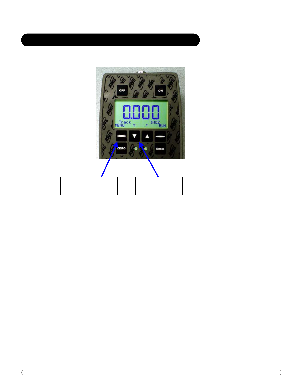
The four buttons on the bottom row are programmable or "Soft Buttons". The
functionality of the buttons will vary with the current selection. There are two
ways to change settings, or otherwise gain access to the operation of the
tester:
1. Live programming: Where the "soft" buttons have text above them,
pressing the button will scroll through the options. In the picture above,
pressing the down arrow will scroll through the Modes of Operation. These
include Peak, 1stPeak and Track. The Up Arrow will scroll through the
engineering units.
2. Menu Driven: There are two sets of menus in the display.
SELECTS MODE
OF OPERATION
Page 7
AWS-4050 Guide
a. Bottom right Oval button will scroll through the Tester Operating
Functions. For basic testers, this includes the RUN MODE and MEMORY
(MEM) MODE. Toggling this button will change the functions of the
other soft buttons appropriately.
b. MENU (bottom left oval) will take you to the main menu system.
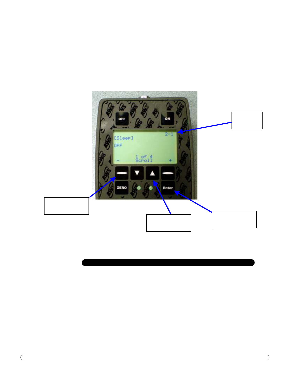
Shown below is a sample of one menu screen
MENU
LOCATION
MENU ACTION
BUTTONS
MENU SCROLL
BUTTONS
RETURNS TO
PREVIOUS MENU
MENU TREE
Operation Overview: There are 8 buttons on the display face: Off, On, four
(4) programmable or ‘soft’ buttons Zero and Enter. The exact function of the
soft buttons is defined by the bottom two rows of text and will vary depending
on the current mode of operation. Pressing the ENT button will take you back
to the previous screen, until you return to the run mode.
Button Operation:
Run Mode (Current mode displayed):
Page 8
AWS-4050 Guide
ON: Clears the peak reading if saved, Zero’s the display and erases the
memory location otherwise.
ENT: Save current reading in memory if memory is on and clears the peak
reading.
Memory Mode (MEM displayed instead of Run):
ON: Goes to run mode without erasing memory location.
ENT: Scrolls to next empty location.
Either Mode:
RUN -> MEM: (soft button) changes the mode of the arrow buttons.
Up and Down: (soft buttons) Units and mode respectively for RUN; Memory
location for MEM. Depends on the right programmable button.
MENU: Enter menus.
MENU Operation:
ENT: Previous menu.
Up and Down: Scroll through the current menu.
Programmable keys: Menu actions. The text varies depending of the active
menu selection.
MENU TREE:
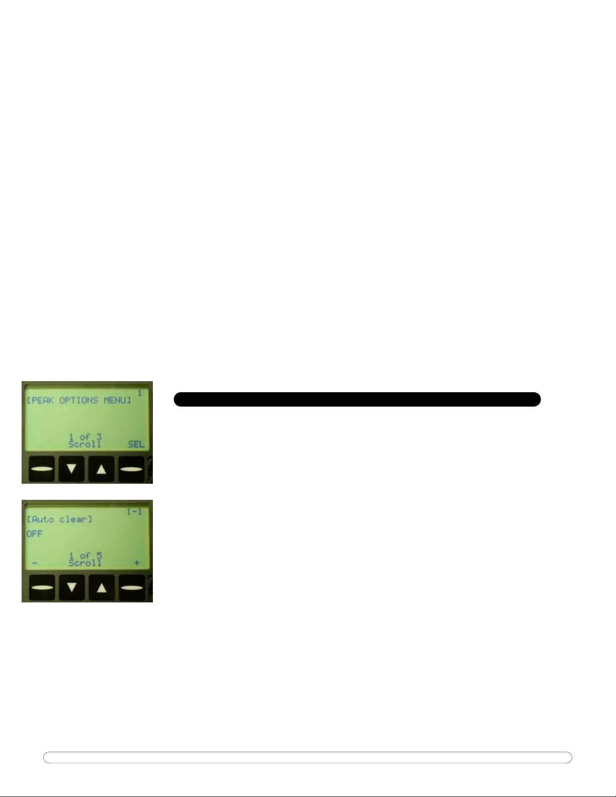
1 PEAK OPTIONS MENU
SEL: Enters menu.
1-1 Auto clear
+, - Set time in seconds.
Auto-clear works in Peak and 1stPeak modes, freeing the operator
from manually clearing the display after taking a reading. Auto-clear can be
set from one to nine seconds, or completely off.
With AutoClr disabled, this reading will continue to display until the
operator stores it by pressing the ENT button, or clears it by pressing the On
button.
Pressing the + key will change "Off" to a value of "1", referring to the
number of seconds the system will hold a reading on the screen before
clearing. Repeatedly press arrow key to scroll from "Off to "9". When the
desired value is shown, press the enter button.
Once the unit is returned to operational mode, AC will show on the
bottom of the display. Because AutoClr is now active, this reading will show for
the user specified number of seconds and then clear the display. From now on,
every reading will clear and be stored automatically into memory.
* Remember AutoClr will not work in Track Mode.
Page 9
AWS-4050 Guide
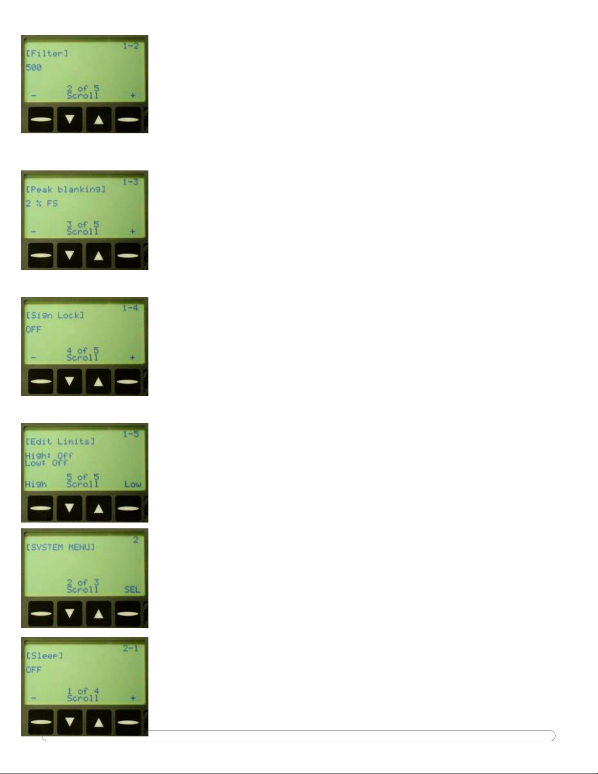
1-2 Filter
+, - Set filter value in Hz.
125, 250, 500, 1000, 1500 & 2000.
1-3 Peak Blanking
+, - Set blanking in percent of full scale.
Peak Blanking sets the minimum threshold at which torque is captured
as a peak. Pressing the + and - buttons will toggle this from 2% through 50%
of Full Scale. Pressing the ENT button will accept this value and return to Run
Mode.
1-4 Sign Lock
+, - Toggle On or Off.
The Sign Lock feature allows the user to select the torque direction of
the peak to be captured. With Sign Lock ON, the initial direction or sign is the
default direction. Any peak measured in the non-selected direction will be
measured, but not captured as a peak. To reset the sign, either cycle the
power or zero the unit.
With Sign Lock OFF, the tester will capture both CW and CCW torque.
1-5 Edit Limits
High or Low edits that limit.
Limit editing:
Up and Down: Change the digit specified (5 is decimal point, OFF turns
the limit off)
DIG: Changes which digit to edit.
ENT: Accepts changes.
2 SYSTEM MENU
SEL: Enters menu.
2-1 Sleep
+, -: Set time in minutes.
To conserve battery life, the display is equipped with a "sleep" mode,
which sets the limit to standby after a user-settable amount of time has
passed without activity. Press the + key to increase the number of minutes the
unit will wait for input, or the - key to decrease the number. The highest
Page 10

AWS-4050 Guide
possible sleep setting is 20 minutes. Press ENT to accept the value and
continue to the next function.
2-2 Lockout Menu
SEL: Enter menu.
2-2-1 Mode Lockout
+, -: Toggle on or off.
2-2-2 Units Lockout
+, -: Toggle on or off.
2-2-3 Scroll Lockout
+, -: Toggle on or off.
2-3 Contrast
+, -: Change the contrast of the display.
2-4 Information
SYS: Gives detailed info about the system.
TD: Gives detailed info about the transducer.
3 DATA MENU
SEL: Enters menu.
3-1 Print Memory
Send: Prints the currently saved readings.
3-2 Clear Memory
CLR: Followed by ENT clears the readings saved in memory.
Page 11

AWS-4050 Guide
3-3 Reset All
CLR: Followed by ENT clears all readings and all sets. Should be used
approximately every 5000 readings.
DESCRIPTION OF FUNCTIONS
The following is a description of the standard features of the AWS product line.
OPERATING MODE
Current operating mode (Peak, 1st Peak or Track) will show on the display.
Press the Πkey to toggles between them.
Peak
Displays and retains the maximum torque experienced by the wrench, as
occurs when operating the wrench in the tightening direction. The Peak Mode
is used for all power tools and some dial wrenches.
1st Peak
Detects the “first peak” of torque experienced by the wrench, capturing the
initial torque as occurs when the torque wrench cams over. First Peak is used
primarily for Click torque wrenches and cam over screwdrivers.
Track
Displays torque as it is being applied to the transducer. Track mode is used
primarily for verifying calibration of the unit.
SELECTING A TRANSDUCER
IMPORTANT NOTE: On power-up, the transducer that is selected will be active
and ready to use. When changing the shaft, you MUST Zero the unit. Do this
by pressing the On/Zero. The shaft capacity can be verified by going to the
Information screen in the Systems Menu (2-4). Full Scale capacity screen is
shown. Press the ENT button twice to return to the run mode.
ENGINEERING UNITS
Shows the current engineering units. Press the key to cycle through
Page 12

AWS-4050 Guide
the eight possible choices: Kgf m, KgfCm, gfCm, cNm, Nm, FT LB, IN LB, IN
OZ.
FULL SCALE
This screen shows the Full-Scale value of the Torque Shaft. This is not a field
adjustable value.
LOW LIMIT
Use the low limit setting as a means of visually flagging the operator when a
reading fails to reach a desired minimum value. A small down arrow will
appear on the screen if a peak is captured below the limit setting.
The limit is adjusted by using the navigation buttons to set the first four digits
to the desired value. The fifth digit is used to select the decimal point
position. The up and down buttons under the “Soft” button
change the value from 0-9. Pressing the “soft”
positions. When the correct value is entered, pressing the
return you to the menu system.
DIG will scroll through the digit
Change will
ENT button will
Once all the digits have been set, press the MEM key to accept the value and
return to Program Function mode. The next time a reading is taken, "LO" will
appear on the display if the captured value is less than the low limit
HIGH LIMIT
Use the high limit setting as a means of visually flagging the operator when a
reading falls over a desired maximum value. High limits are set in the identical
way as low limits. Please refer to the Low Limit section for details.
NOTE ON LIMITS: The green LED on the front of the display will flash when a
peak is captured that falls within the limit setting.
Page 13

AWS-4050 Guide
SERVICE AND WARRANTY
SERVICE
To ensure the best possible support for our customers, Advanced Witness Series
maintains a complete calibration and repair facility for all its products. We keep in stock
most replacement parts for torque testers, transducers, and our line of digital wrenches.
When you buy a product from us, the only place you need to go for parts and service
is...us! For service, call (408) 453-5070, Monday through Friday, between the hours of
9:00am and 5:00pm Pacific Coast Time.
THE WARRANTY CARD
In order to ensure protection of the warranty as described below, you MUST fill in the
appropriate information on the warranty card that came with your unit and return it to
Advanced Witness Series, Inc. within 30 days of receipt of item.
We wish to call your attention to the fact that this system and various components need
calibration and certification on a periodic basis. By returning the card to us, you will
receive timely notification as to when this re-calibration and re-certification is due.
STATEMENT OF LIMITED WARRANTY
ADVANCED WITNESS SERIES, INC. products are warranted free of defects in material
and workmanship for a period of one (1) year from date of shipment. This warranty
does not include failures due to application of torque to transducers or loaders beyond
the stated capacity, operating system with a damaged transducer cord, nor any other
misuse, abuse, or tampering. When used with impact type wrenches, the warranty is
limited to the electronic digital display units only. This warranty does not cover
calibrations.
All freight charges are the responsibility of the company or individual returning the
item(s) for repair. Freight collect shipments will not be accepted.
Any modification to any of this equipment, without the express written approval of
ADVANCED WITNESS SERIES, INC., will void this warranty. ADVANCED WITNESS
SERIES disclaims any and all liability, obligation or responsibility for the modified
product; and any claims, demands or causes of action for damage or for personal
injuries resulting from the modification and/or use of such a modified ADVANCED
WITNESS SERIES product.
ADVANCED WITNESS SERIES, INC.'S OBLIGATION WITH RESPECT TO ITS PRODUCTS
SHALL BE LIMITED TO REPAIR OR REPLACEMENT, AND IN NO EVENT, SHALL ADVANCED
WITNES SERIES, INC. BE LIABLE FOR ANY LOSS OR DAMAGE, CONSEQUENTIAL OR
SPECIAL, OF WHATEVER KIND OR NATURE OR ANY OTHER EXPENSE WHICH MAY ARISE
IN CONNECTION WITH OR AS A RESULT OF SUCH PRODUCTS OR THE USE OR
INFORMATION THEREOF IN A JOB. THIS WARRANTY IS EXPRESSLY MADE IN LIEU OF
ALL OTHER WARRANTIES OR MERCHANTABILITY AND FITNESS FOR A PARTICULAR
PURPOSE. NO EXPRESS WARRANTIES AND NO IMPLIED WARRANTIES WHETHER OF
MERCHANTABILITY OR FITNESS FOR A PARTICULAR PURPOSE OR OTHERWISE OTHER
THAN THOSE EXPRESSLY SET FORTH ABOVE SHALL APPLY TO ADVANCED WITNESS
SERIES.
Page 14

AWS-4050 Guide
AWS-4050 Torque Display
For Use with Intellect Transducers
USER'S GUIDE
August, 2006
ADVANCED WITNESS SERIES, INC.
910 BERN COURT #100
SAN JOSE, CA 95112
(408) 453-5070
www.awitness.com
 Loading...