

Page 1

1
Table of Contents
1.0 Introduction . . . . . . . . . . . . . . . . . . . . . . . . . . . . . . . . . . . . . . . . . . . . . . 02
1.1 Unpacking
1.2 Repacking and Storage
2.0 Installation . . . . . . . . . . . . . . . . . . . . . . . . . . . . . . . . . . . . . . . . . . . . . . .
03
2.1 Mounting
2.2 Interconnections
2.3 Fuse
2.4 Main Chasis
3.0 Internal Operations . . . . . . . . . . . . . . . . . . . . . . . . . . . . . . . . . . . . . . . . 05
3.1 Controls
3.2 Internal Operation
4.0 External Operations . . . . . . . . . . . . . . . . . . . . . . . . . . . . . . . . . . . . . . .
06
5.0 Circuit Descriptions . . . . . . . . . . . . . . . . . . . . . . . . . . . . . . . . . . . . . . . 07
5.1 Normal (RUN) Operation
6.0 Flashlamp Replacement . . . . . . . . . . . . . . . . . . . . . . . . . . . . . . . . . . . . 08
7.0 Specifications . . . . . . . . . . . . . . . . . . . . . . . . . . . . . . . . . . . . . . . . . . . . 09
8.0 Appendix: Modification for 230 VAC Operation . . . . . . . . . . . . . . . . . 11
9.0 Warranty . . . . . . . . . . . . . . . . . . . . . . . . . . . . . . . . . . . . . . . . . . . . . . . . . 12
12
5.0 WARRANTY
ELECTROMATIC Equipment Co., Inc. (ELECTROMATIC) warrants to the
original purchaser that this product is of merchantable quality and confirms
in kind and quality with the descriptions and specifications thereof. Product
failure or malfunction arising out of any defect in workmanship or material in the
product existing at the time of delivery thereof which manifests itself within one
year from the sale of such product, shall be remedied by repair or replacement of
such product, at ELECTROMATIC’s option, except where unauthorized repair,
disassembly, tampering, abuse or misapplication has taken place, as determined
by ELECTROMATIC. All returns for warranty or non-warranty repairs and/or
replacement must be authorized by ELECTROMATIC, in advance, with all
repacking and shipping expenses to the address below to be borne by the
purchaser.
THE FOREGOING WARRANTY IS IN LIEU OF ALL OTHER WARRANTIES,
EXPRESSED OR IMPLIED, INCLUDING BUT NOT LIMITED TO, THE WARRANTY
OF MERCHANTABILITY AND FITNESS FOR ANY PARTICULAR PURPOSE OR
APPLICATION. ELECTROMATIC SHALL NOT BE RESPONSIBLE NOR LIABLE
FOR ANY CONSEQUENTIAL DAMAGE, OF ANY KIND OR NATURE, RESULTING
FROM THE USE OF SUPPLIED EQUIPMENT, WHETHER SUCH DAMAGE
OCCURS OR IS DISCOVERED BEFORE, UPON OR AFTER REPLACEMENT
OR REPAIR , AND WHETHER OR NOT SUCH DAMAGE IS CAUSED BY
MANUFACTURER’S OR SUPPLIER’S NEGLIGENCE WITHIN ONE YEAR FROM
INVOICE DATE.
Some State jurisdictions or States do not allow the exclusion or limitation of
incidental or consequential damages, so the above limitation may not apply to
you. The duration of any implied warranty, including, without limitation, fitness
for any particular purpose and merchantability with respect to this product, is
limited to the duration of the foregoing warranty. Some states do not allow
limitations on how long an implied warranty lasts but, not withstanding, this
warranty, in the absence of such limitations, shall extend for one year from the
date of invoice.
ELECTROMATIC Equipment Co., Inc.
600 Oakland Ave. Cedarhurst, NY 11516—USA
Tel: 1-800-645-4330/ Tel: 516-295-4300/ Fax: 516-295-4399
Every precaution has been taken in the preparation of this manual. Electromatic Equipment Co., Inc., assumes
no responsibility for errors or omissions. Neither is any liability assumed for damages resulting from the use of
information contained herein. Any brand or product names mentioned herein are used for identification purposes only, and are trademarks or registered trademarks of their respective holders.
Page 2
2
1.0 INTRODUCTION
The AS4020, AS4060 and AS4200 Series Machine Vision Strobes provide short
duration high intensity light pulses for industrial vision applications. The three
models are identical, excluding the AS4200 which provides higher flash repetition
rate at a lower output energy level than the AS4020 and AS4060. Refer to
Specifications for details.
The AS4000 Series unit comes complete with an input power cable and connector,
and an AS type Xenon Flashlamp. Each unit uses a NEMA Type 13 enclosure.
Light output is focused on a port configured to accept a fiber-optic cable. This
allows light transmission to an area remote from the instrument. When coupled to a
CCS/CID camera, the AS4000 Series strobe freezes motion, eliminating blur from
the camera image and enhancing image quality
The AS4000 Series can be used for a variety of industrial robotics production
applications including.
Sorting Color Differentiation Part Recognition
Counting Contaminant Detection Motion Sensing
Label Reading Component Orientation Edge Detection
Motion Sensing Package Integrity Verification Web Printing Inspection
ATTL input pulse from a camera unit is used to initiate the AS4000 Series flash
Operational power requirements are 115VAC or 230VAC, 50/60 Hz single phase
power with a ground. Standard production units are factory set to either 115 VAC
or 230 VAC.
1.1 Unpacking
The AS4000 Series strobe is shipped completely assembled in one container.
Retain a and store all packing material for use during reshipment or return to
the factory.
Examine the package for signs of damage or mishandling. Contact the carrier
immediately if there are any signs of damage. DO NOT proceed with installation if there are any signs of damage or mishandling.
The Xenon Flashlamp is a high-pressure gas-filled device.
Wear safety glasses during handling
The Xenon Flashlamp is particularly vulnerable to rough treatment during
shipping. After removing the AS4000 Series unit from the shipping container,
raise the cover of the unit and observe the flashlamp mounted inside. Damage
to the flashlamp should be immediately apparent.
1.2 Repacking and Storage
The AS4000 Series strobe needs to be placed in its original packaging for
long periods of storage, when shipped to another location or returned to the
factory for repair. If the original packing material is not available, the unit
should be packaged in a container with sufficient protective material to ensure
that the unit cannot move within the package and is protected from damage.
Store in a dry area at a temperature of –10 °F to 194 °F (–40 °C to 90 °C).
WARNING
11
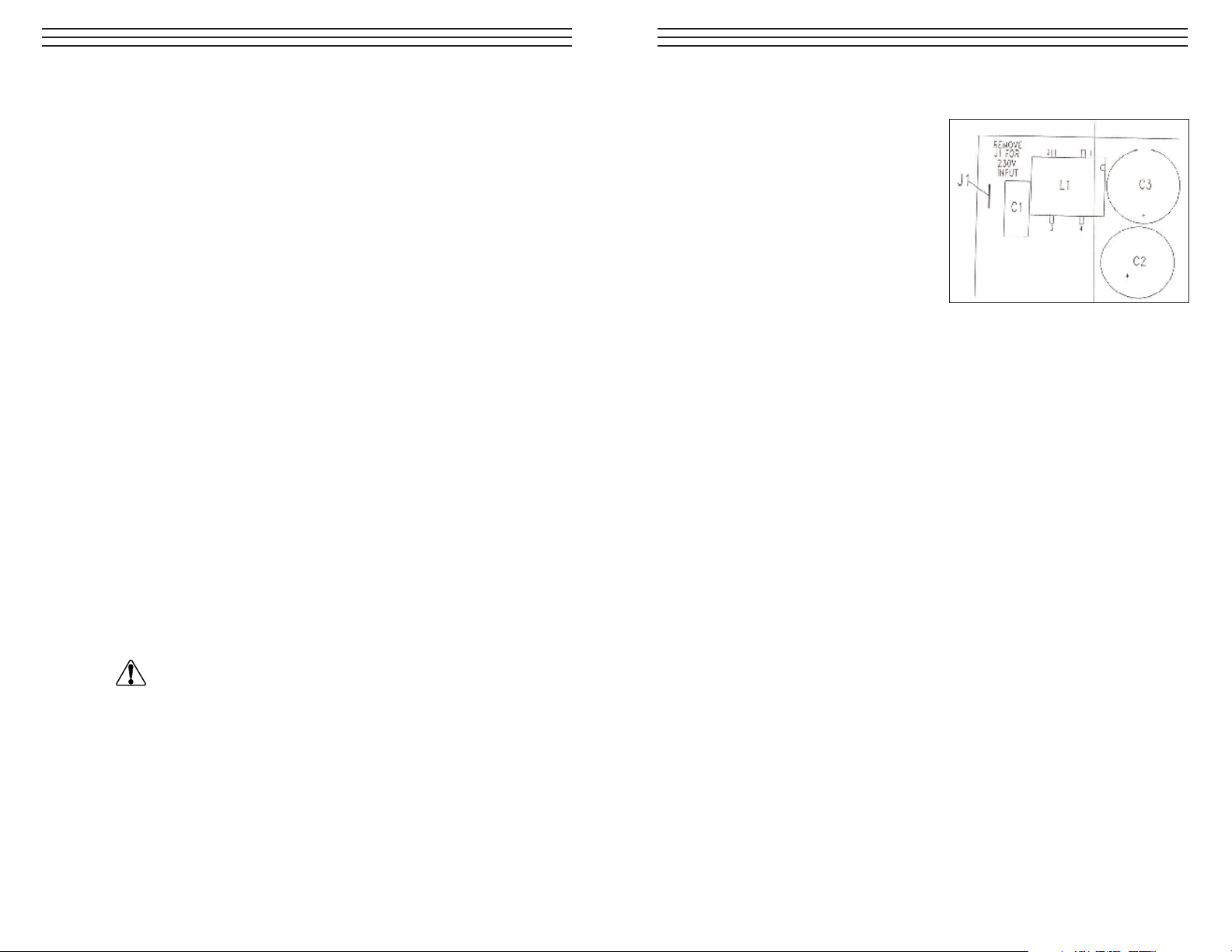
8.0 APPENDIX A: MODIFICATION FOR 230 VAC OPERATION
The 230VAC version of the AS4000 Series
strobe is available direct from the factory,
so that user modification should not be
required. However, in the event that
conversion from 115VAC to 230VAC
becomes necessary in the field, the user
may perform the following:
Cut or Remove the jumper J1 in the
upper left-hand comer of the AS3907
printed circuit board. Cutting J1 converts
the system for 230VAC operation.
If a reverse conversion (230VAC to 115VAC) becomes necessary, return the unit to
the factory. An attempt by the user to replace J1 will void the warranty and may
result in damage to the unit.
Page 3
3
2.0 INSTALLATION
2.1 Mounting
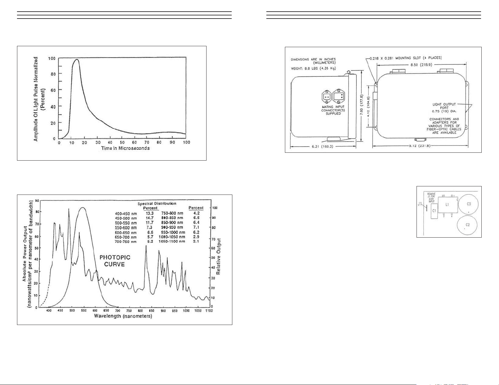
Four holes in the base of the AS4000 Series unit provide for secure mounting
in any position. Mounting hardware is not provided with the unit. Refer to
Figure above.
2.2 Interconnections
Two connectors and a fuse are provided at the rear
of the AS4000 Series enclosure. Refer to Figure.
Power Connector: The input power cable
(supplied) is connected to the smaller connector.
Operating power is 115VAC or 230VAC (depending on the modification),
50/60 Hz single phase power with a ground.
Control Cable: Acontrol cable (not supplied) is connected to the larger
connector signal input. Th signal inputs are:
Pin 1: Trigger input—5V, 20mA pulse. Triggers on positive-going edge.
Pin 2: No connection.
Pin 3: Isolated input common for return of Pin 1 and Pin 5.
Pin 4: An external reference input signal voltage, 0 to 6V maximum
or 1.7V minimum to keep lamp flashing.
Pin 5: Lamp failure signal output. This signal confirms the lamp has flashed
flashed as programmed. It is 12V high, with a width approximately
the same as the light pulse (5µS).
Pin 6: External reference return. Chassis ground.
10
Light Output Waveform (based on 12 µF Capacitor)
Spectral Distribution Of Light Pulse (based on 12 µF Capacitor)
Page 4
4
CCOONNNNEECCTTOORR HHAARRDDWWAARREE
Part No. Type Description
CN104 Power Connector plug with strain relief, Hirschmann
Type STAK 20 (Included on line cord)
CN103 Power Connector plug for panel mounting,
Hirschmann Type STASEI 2 (Included with unit)
CN106 Power Security bracket, Hirschmann Type STASI 3
(Included with unit)
CN105 Control Connector for cable mounting, Hirschmann
Type Stak 5, 5+ ground signal connector
(for cable) with six crimp contacts
CN102 Control Connector plug for panel mounting, Hischmann
Type STASEI 5, 5+ ground connector
(Included with unit)
CN100 Control Security bracket, Hirschmann Type STASI 2
(Included with unit)
2.3 Fuse
A one amp fuse located on the NEMA enclosure provides AC line input
protection.
2.4 Main Chasis
9
7.0 SPECIFICATIONS
Optical
Broadband light output 20 millijoules per flash at fiber-optic plane
Flash repetition rate AS4020 - 20 flashes per second maximum
AS4060 - 60 flashes per second maximum
AS4200 - 200 flashes per second maximum
Input energy to flashlamp AS4020 - 2.0 joules per flash maximum at 20 Hz
AS4200 - 0.2 joules per flash maximum at 200 Hz
Light output pulse Less than 25 µS pulse width at all energy settings
at 1/3 of peak energy
Lifetime of flash.lamp 100 million flashes while maintaining more
than 70% of initial intensity (estimated)
Electrical
Power Line Requirement 115/230 VAC, 50/60 Hz
Power Consumption 0.5A maximum
Trigger Signal +5V at 20mA (optically isolated)
Trigger Pulse Width 10 µ S (minimum)
Non-Synchronizing Time 200 µS (minimum)
Before Pulse
Turn-On Delay Command l0 µS (Typical)
To Flash
Environmental
Operating Temperature Range –10 to 110 °F (-23 to +43 °C)
Storage Temperature Range –40 to +194 °F (–40 to +90 °C)
Operating Altitude Range Sea Level to 10,000 ft. (3,000 m)
Operating Humidity Range 0 to 90% noncondensing
Shock and Vibration 1.5g, 5 to 200 Hz, per MIL-STD-810C
Enclosure NEMAType 13; Confirms to JIC Std, EGP-1-1967
and European Std IEC 529, 1P65; Listed by
Underwriters Laboratories, Inc.
Flash Intensity
Power Indicator
& Mode Switch
(remove cover
for access)
Page 5
8
6.0 FLASHLAMP REPLACEMENT
1. Disconnect power from unit.
2. Wait one minute to allow the lamp to cool and energy to capacitor to discharge.
3. Raise the cover.
4. Ground the rear lamp e1ectrode holder using a screwdriver.
5. Loosen both socket head screws on lamp supporting bracket.
6. Remove lamp cathode ground screw.
7. Gently grasp the cathode ground wire and remove lamp.
8. To install a new lamp reverse the removal procedure,
9. The lamp is in the correct axial alignment when the rear electrode butts
the back of the electrode holder.
Install a new lamp by reversing the removal procedure. Reconnect the anode
wire to the trigger circuit. Secure the ground wire to the PC board.
WARNING
DANGER – The Xenon Flash lamp is a high-pressure, gas-filled
device. Wear Safety glasses during handling
DANGER – HIGH VOLTAGE. Disconnect power cable and
control cable before replacing Flashlamp.
CAUTION – During installation, do not apply torque to the
lamp end seals.
5
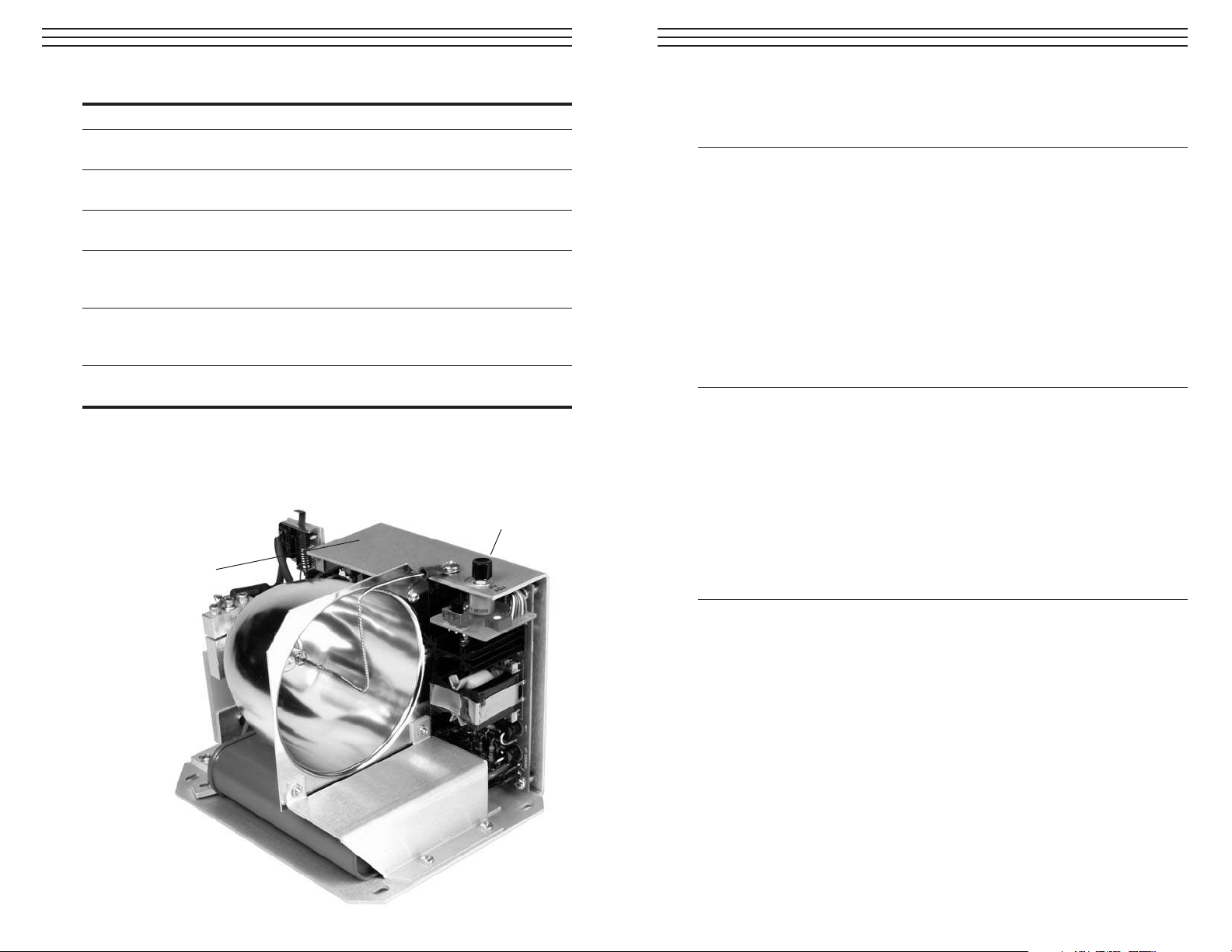
3.0 INTERNAL OPERATIONS
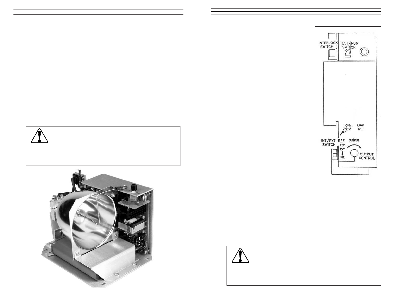
3.1 Controls
In the AS4000 Series, a cover interlock
switch automatically breaks the circuit
whenever the unit is opened. this is to
help protect the operator from danger
of electric shock. To operate the unit
while the cover is open, pull up on the
interlock tab.
Atest/run switch is provided for testing
the unit in the absence of input signals.
when the switch is th the TEST position,
the unit is on and the lamp flashes at a
fixed rate of 20 pps. For remote
operation, the switch must be placed
in the RUN position.
Light output intensity can be varied over
a range of approximately 10:1 by means
of an output control. A two-position slide
switch is used to select either internal
mode of control or externa reference
control from the input connector. Light
output can be varied by means of the
output control knob.
3.2 Internal Test & Operation
Check the AS4000 Series Strobe for proper operation using the following
procedures (refer to figure above):
1. Disconnect power from unit
2. Lift the lid opening the enclosure
3. Visually inspect the flashlamp for damage
4. Place the TEST/RUN Switch in the TEST position
5. Reconnect power to the unit
6. Place the EXT/INT Reference Switch in the INT REF position
7. Lift the cover interlock switch to its up position
WARNING
Avoid looking directly at the high intensity light flash, either at
the unit itself or at the end of the fiber-optic cable. This could
result in damage to the eyes.
DANGER – HIGH VOLTAGE. Use extreme caution when
operating the interlock switch, avoid contact with the front
electrode of the flashlamp
Page 6

6
08. The strobe should pulse at 20 pps.
09. Allow the cover interlock switch to return to the downward position.
This will cut off power to the unit.
10. Turn the veristor HV ADJ control through its complete range, stopping
at intervals to lift the cover interlock switch. Observe that light output
variations occur over the total range of th HV ADJ control
11. Return the TEST/RUN Switch to RUN position. Return the EXT/.INT
Reference Switch to the EXT REF position.
4.0 EXTERNAL OPERATION
Operate the AS4000 Series Strobe in a production environment using the following
procedure
1. Mount the AS4000 Series unit on a stable base in a location convenient to
the production line to be viewed
2. Using option Nosepiece Adapter, connect a fiber-optic cable to the AS4000
Series light output port. Position the cable to distribute light to the desired
area.
3 Lift the lid, opening the enclosure.
4. Place the TEST/RUN Switch in the RUN position.
5. Place the EXT/INT Reference Switch in the EXT/REF position
6. Close and secure the cover.
7. Connect power to the unit.
8. Connect a signal level input cable to the connector at the rear of the unit.
9. Connect the signal level input cable to a CCD/CID camera system that
will provide TTL pulses to initiate flashes.
The system in now set to stop motion in the desired industrial vision application.
7
5.0 CIRCUIT DESCRIPTION
5.1 Normal Operation (RUN MODE)
The AS4000 Series strobe is made up of four functional circuit elements.
1. AS3906 Power Supply Board
2. AS3907 Voltage Control Board
3. AS3908 Add-On Board
4. Flashlamp storage capacitor and triggering circuit
Apower cable supplied with the unit provides input power. Asignal level
input cable supplied by the customer provides operational support.
An energy storage capacitor stores energy provided by the AS3906 Power
Supply Board. Atrigger pulse discharges the capacitor into the flashlamp
causing the lamp to flash.
The Power Supply Board recharges the energy storage capacitor during the
interval between flashes.
During normal operation, the lamp will flash a maximum repetition rate of 60
when a trigger input pulse is applied between pins I and 3 of the signal input
connector.
Atransformer in the flashlamp circuit senses flashlamp current. Pins 3 and 5
of the signal input connector monitor the resulting signal. This signal is
12 volts high with a width approximately th same as the light pulse (5 µS),
Page 7
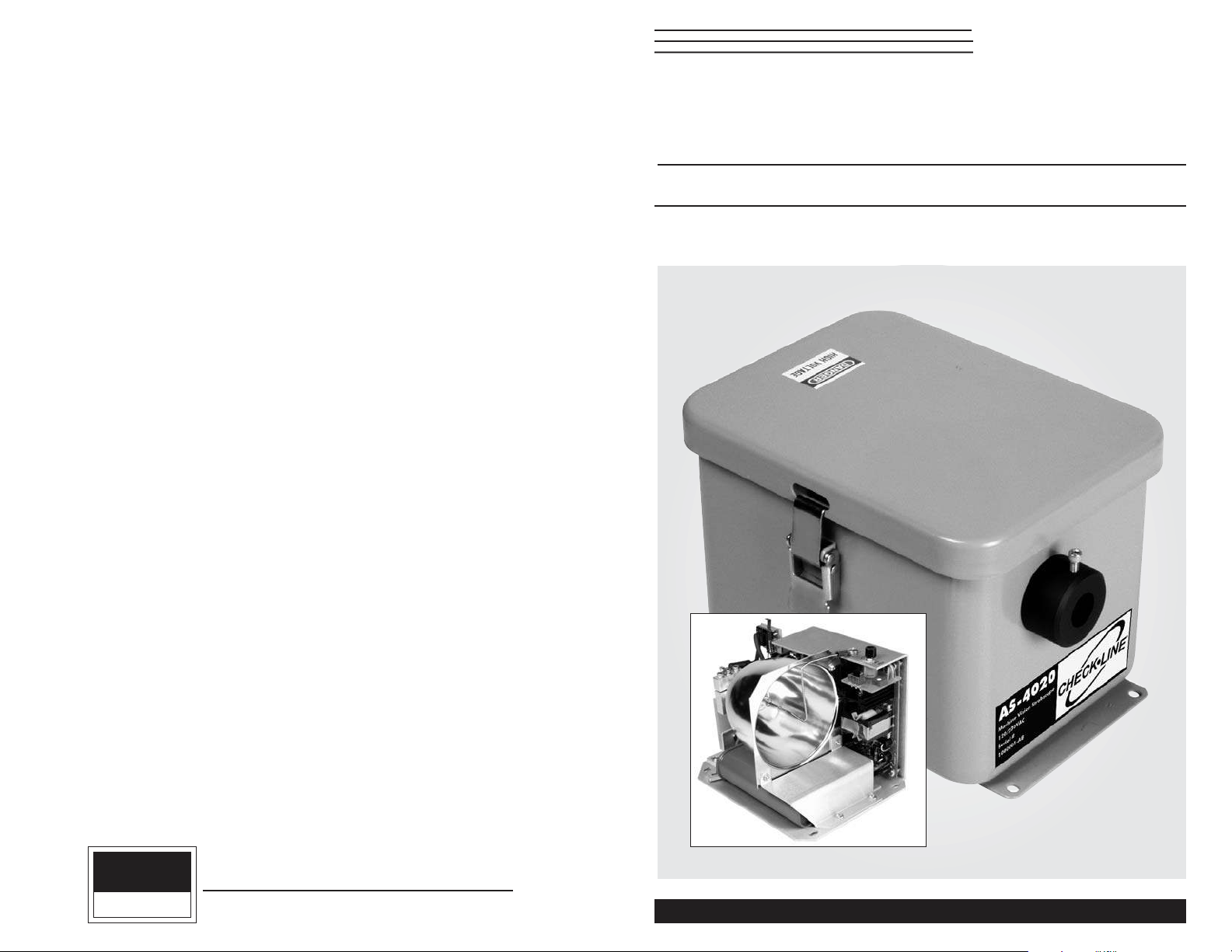
MACHINE VISION STOBOSCOPES
AS4000 SERIES
Operating Instructions
CHECK•LINE
®
BY ELECTROMATIC
ELECTROMATIC
E Q U I P M E N T C O., I N C.
600 Oakland Ave., Cedarhurst, NY 11516–U.S.A.
TEL: 516-295-4300 • FAX: 516-295-4399
CHECK•LINE
®
INSTRUMENTS
 Loading...