

Page 1

AKD®2G-Sxx with Functional Safety Option 1
STO - SIL2
Installation Manual, English
Manual Edition: C, July 2020
Safety Edition: S102, April 2020
Valid for AKD®2G-S HardwareRevision A
Part Number 907-200003-00
Original Document
For safe and proper use, follow these
instructions. Keep for future use.
Beta Drives: All approvals are pending.
Page 2
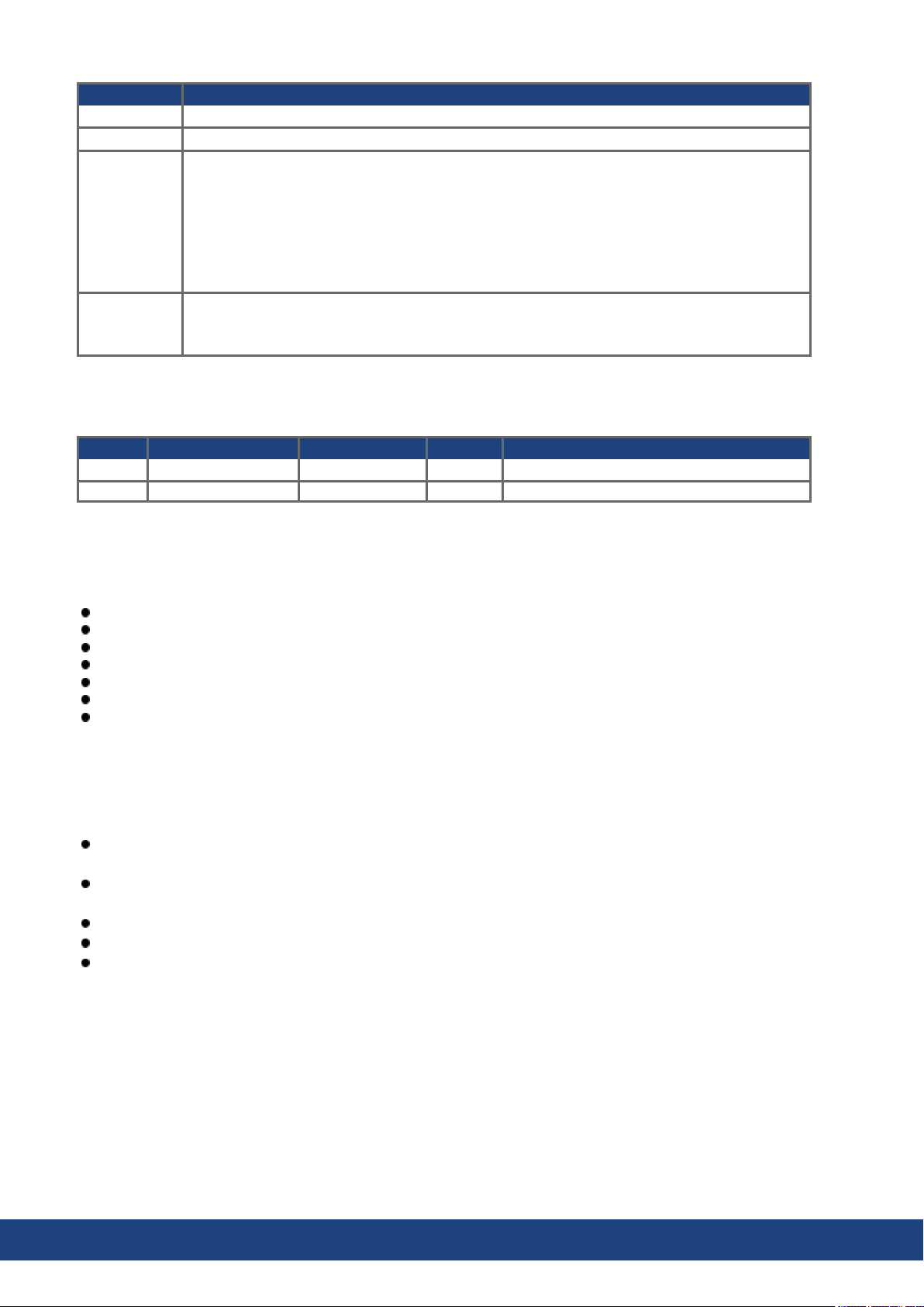
Record of Document Revisions
Edition Remarks
... Table with lifecycle informationof this document (➜ # 155)
A, 12/2019 First edition
Electrical data updated, UL markings updated, default setting: STO active, connector tightening torque added to connector pin assignments, regen resistor wiring updated,
AXIS#.ZEROx keywords updated for stop diagrams, X1/X2 feedback voltage 11V, X23 max.
B, 04/2020
current 350mA, FS trouble shooting updated, SFA voltage/current values, continuous brake
powerof external regen resistor reduced, CE: external EMC mains filters for 7V models, max.
cable length for unshielded I/O lines, 24V supply with X10T, SFF=75%, PROFINET added,
EtherNet/IP added, X22 digital feedbacks added, breakers for 7V models removed
Performance data table corrected, mounting M/P values synchronized, X23/X41 pinout
C, 07/2020
Step/Dir&CW/CCW updated, chapter CAN terminationimproved, PROFINET/EtherNet-IP
label CHx->Portx, UL Markings updated, Modbus added
Hardware Revision (HR)
AKD2G Firmware Workbench KAS IDE Remarks
A from 02-00-00-000 from 2.00.0.0000 from 3.01 First revision
Trademarks
AKD is a registered trademark of Kollmorgen Corporation.
EnDat is a registered trademark of Dr. Johannes Heidenhain GmbH.
EtherCAT is a registered trademark and patented technology, licensed by Beckhoff Automation GmbH, Germany.
EtherNet/IP is a registered trademark of ODVA, Inc.
HIPERFACE is a registered trademark of Max Stegmann GmbH.
PROFINET is a registered trademark of PROFIBUS and PROFINET International (PI).
Windows is a registered trademark of Microsoft Corporation.
Current patents
US Patent 2017/0211640 (method and apparatus for power saving, fail-safe control of an electromechanical
brake), patent pending
US Patent 16,247,478(method and apparatus for limiting the output voltages of switching mode powersupplies), patent pending
US Patent 8,154,228 (Dynamic Braking For Electric Motors)
US Patent 8,214,063 (Auto-tuneof a Control System Based on Frequency Response)
US Patent 10.374.468(System and method for improvedDC power line communication)
Patents referring to fieldbus functions are listed in the matching fieldbus manual.
Technical changes which improve the performance of the device may be made without prior notice!
This document is the intellectual property of Kollmorgen. All rights reserved. No part of this work may be reproduced
in any form (by photocopying, microfilm or any other method) or stored, processed, copied or distributed by electronic
means without the written permission of Kollmorgen.
2 Kollmorgen | kdn.kollmorgen.com | July 2020
Page 3

AKD2G-S Installation Manual, Safety 1 | Table of Contents
1 Table of Contents
1 Table of Contents 3
2 General 9
2.1 About thisInstallationManual 10
2.2 Using the PDF Format 10
2.3 SymbolsUsed 11
2.4 AbbreviationsUsed 12
3 Product Safety 13
3.1 You shouldpay attention to this 14
3.2 Use asDirected 16
3.3 Prohibited Use 17
3.4 Warning note labels 17
3.4.1 Notes placedon the product 17
3.4.2 Adhesive labelin the package 17
3.5 Shock-hazard Protection 18
3.5.1 Leakage current 18
3.5.2 Residual current protective device (RCD) 18
3.5.3 Isolatingtransformers 18
3.6 Stop / Emergency Stop / EmergencyOff 19
3.6.1 Stop 19
3.6.2 Emergency Stop 20
3.6.3 Emergency Off 20
4 Product life cycle handling 21
4.1 Transport 22
4.2 Packaging 22
4.3 Storage 22
4.4 Installation, setup and normal operation 23
4.5 Decommissioning 23
4.6 Maintenance and cleaning 23
4.7 Disassembly 23
4.8 SystemRepair 24
4.9 Disposal 24
5 Package 25
5.1 PackageSupplied 26
5.2 Nameplate 26
5.3 Part Number Scheme 27
6 Technical description and data 28
6.1 The AKD2G Familyof Digital Drives 29
6.2 Ambient Conditions,Ventilation, and Mounting Position 31
6.3 MechanicalData 31
6.4 Performance Data 32
6.5 Electrical data 33
6.5.1 Singleaxisvariants (S) 33
6.5.1.1 Mains supply data, 1 phase AC, type AKD2G-Sxx- (S) 33
6.5.1.2 Mains supply data, 3 phase AC, type AKD2G-Sxx- (S) 33
6.5.1.3 Mains supply data, DC, type AKD2G-Sxx- (S) 33
6.5.1.4 Auxiliary voltage input data, 24VDC, type AKD2G-Sxx- (S) 33
6.5.1.5 Output data, type AKD2G-Sxx- (S) 34
6.5.2 Dual axisvariants(D: I1=I2) 35
6.5.2.1 Mains supply data, 1 phase AC, type AKD2G-Sxx- (D) 35
6.5.2.2 Mains supply data, 3 phase AC, type AKD2G-Sxx- (D) 35
Kollmorgen | kdn.kollmorgen.com | July 2020 3
Page 4
AKD2G-S Installation Manual, Safety 1 | Table of Contents
6.5.2.3 Mains supply data, DC, type AKD2G-Sxx- (D) 35
6.5.2.4 Auxiliary voltage input data, 24VDC, type AKD2G-Sxx- (D) 35
6.5.2.5 Output data, type AKD2G-Sxx- (D) 36
6.6 Electrical Motor Braking 37
6.6.1 Drive DynamicBraking 37
6.6.2 Regeneration breaking 37
6.6.2.1 Functional description 37
6.6.2.2 Technical data for AKD2G-Sxx-6V 38
6.6.2.3 Technical data for AKD2G-Sxx-7V 38
6.7 LCD Displayand Push-buttons (B1, B2) 39
6.8 SD Card Slot 41
7 Mechanical Installation 42
7.1 Important Notes 43
7.2 Guide to MechanicalInstallation 43
7.3 Dimensions 44
8 Electrical Installation 45
8.1 Important Notes 46
8.2 Guide to electricalinstallation 47
8.3 Wiring 48
8.3.1 General 48
8.3.2 Mating connectors 48
8.3.3 Cable and Wire Requirements 49
8.3.3.1 Cable material 49
8.3.3.2 Cable Length 49
8.3.3.3 T-Connector wiring 49
8.3.3.4 Cable cross sectionsand requirements 50
8.3.4 Protective Earth connection 51
8.4 EMI NoiseReduction 52
8.4.1 Recommendations for EMI noisereduction 52
8.4.2 Shielding with external shielding busbar 53
8.4.2.1 ShieldingConcept 53
8.4.2.2 ShieldingBusbar 54
8.4.3 Shielding connectionto the drive 55
8.4.3.1 ShieldingConcept 55
8.4.3.2 Grounding plates and shield connection clamps 56
8.4.3.3 Motor connector X1/X2 with shielding connection 56
8.5 Connection Overview 57
8.5.1 Connector Position AKD2G-Sxx-6V 57
8.5.2 Connector Position AKD2G-Sxx-7V 58
8.5.3 Wiring overview, single axisdrive 59
8.5.4 Wiring overview, dual axis drive 60
8.5.5 Connector pin assignments 61
8.5.5.1 X1 and X2: Motor, Brake, Feedback1 61
8.5.5.2 X3: Mains,regen resistor, DC-Bus 61
8.5.5.3 X10: 24 VDC 62
8.5.5.4 X11, X12: EtherNet Fieldbus 62
8.5.5.5 X13, X14: CAN bus (optional) 62
8.5.5.6 X20: Service 62
8.5.5.7 X21: I/O, Feedback 4 63
8.5.5.8 X22: I/O, EEO2, Feedback5 64
8.5.5.9 X23: I/O, EEO1, Feedback3 65
8.5.5.10 X41: SFA Feedback converter, EEO3/EEO4(accessory) 66
8.6 Power and Logic Voltage Supply (X3/X10) 67
8.6.1 Mains power supply(X3) 67
4 Kollmorgen | kdn.kollmorgen.com | July 2020
Page 5

AKD2G-S Installation Manual, Safety 1 | Table of Contents
8.6.1.1 Wiring examplesmains power supply 68
8.6.1.2 Fusing 71
8.6.2 Auxiliary voltage power supply 24 VDC (X10) 75
8.6.2.1 Fusing 75
8.6.2.2 Wiring example24 VDC supply 75
8.7 DC Bus link (X3) 76
8.7.1 Fusing 76
8.7.2 Wiring example with T connectors 77
8.7.3 Wiring example with busbar 77
8.8 Regen resistor (X3) 78
8.8.1 Fusing and Wiring 78
8.9 Motor Power, Brake and Feedback connection 79
8.9.1 Motor connectivity, some examples 79
8.9.2 Motor single cable connection 80
8.9.2.1 Motor Power, Brake and Feedback connectors X1, X2 80
8.9.2.2 Feedbackconnectors X21, X22, X23 81
8.9.3 Motor dual cable connection 82
8.9.3.1 Motor power and motor brake connectors X1, X2 83
8.9.3.2 Feedbackconnectors X1, X2, X41, X21, X22, X23 83
8.9.4 Motor Holding Brake Connection 84
8.9.5 Feedback Connection 86
8.9.5.1 FeedbackConnector X1, X2 87
8.9.5.2 FeedbackConnector X21 88
8.9.5.3 FeedbackConnector X22 89
8.9.5.4 FeedbackConnector X23 90
8.9.5.5 FeedbackConnector X41 (SFA, accessory) 91
8.10 EEO, Electronic Gearing, Master-Slave 92
8.10.1 Emulated Encoder Output (EEO) 92
8.10.2 ElectronicGearing 94
8.10.3 Master-Slavecontrol 94
8.10.3.1 Master-Slaveusing X22 94
8.10.3.2 Master-Slaveusing optionalX23 or X41 94
8.11 EtherNet FieldbusInterface (X11/X12) 95
8.11.1 EtherCAT® 95
8.11.2 PROFINET (available2021) 96
8.11.3 EtherNet/IP (available 2021) 97
8.12 CAN-Bus Interface (X13/X14) 98
8.12.1 CAN-Bus Topology 98
8.12.2 CAN-Bus Wiring 99
8.12.3 Baud rate for CAN-Bus 100
8.12.4 Node Address for CAN-Bus 100
8.12.5 CAN-Bus Termination 100
8.13 ServiceInterface (X20) 101
8.13.1 Possible Network Configurations 101
8.14 Modbus TCP (X20) 102
8.15 I/O Connection (X21/X22/X23) 103
8.15.1 Pinout 103
8.15.2 Technicaldata 104
8.15.3 Analog Input 105
8.15.4 Analog Output 106
8.15.5 DigitalInputs 107
8.15.5.1 Digital-In 1 and 2 107
8.15.5.2 Digital-In 3 to 12 108
8.15.5.3 Digital-In/Out 1 and 2 109
Kollmorgen | kdn.kollmorgen.com | July 2020 5
Page 6

AKD2G-S Installation Manual, Safety 1 | Table of Contents
8.15.5.4 Digital-In/Out 3 to 6 110
8.15.6 DigitalOutputs 111
8.15.6.1 Digital-Out 1 to 6 111
8.15.6.2 Digital-Out 7 and 8 112
8.15.6.3 Digital-In/Out 1 and 2 113
8.15.6.4 Digital-In/Out 3 to 6 113
8.15.6.5 Digital-Out 9, Relaycontacts 114
9 Setup 115
9.1 Important Notes 116
9.2 Guide to drive setup 117
9.2.1 InitialDrive Test Procedure 117
9.2.1.1 Unpacking, mounting, and wiring the AKD2G 117
9.2.1.2 Minimum wiring for drive testwithout load, example 117
9.2.1.3 Confirm connections (example: directlyto PC) 118
9.2.1.4 System integration 118
9.2.1.5 Installand start WorkBench 119
9.2.1.6 Setup the axisin WorkBench 119
9.2.1.7 Enable the axis(Hardware) 119
9.2.1.8 Move the motor axis 119
9.2.1.9 Tune the axis 119
9.2.2 Setup software WorkBench 120
9.2.2.1 Use as directed 120
9.2.2.2 Software description 121
9.2.2.3 Hardware requirements 121
9.2.2.4 Operating systems 121
9.2.2.5 Installation under Windows 7/8/10 122
9.3 Switch-On and Switch-Off Behavior 123
9.3.1 Switch-on behavior instandard operation 124
9.3.2 Switch-off behavior 125
9.3.2.1 Switch-off behavior usingthe AXIS#.DIS command 125
9.3.2.2 Switch-off behavior usinga digitalinput (controlled stop) 126
9.3.2.3 Switch-off behavior usingSTO input (uncontrolled stop) 126
9.3.2.4 Switch-off behavior in the event of a fault 127
9.4 Fault and Warning Messages 130
9.4.1 Fault and warning messages AKD2G 130
9.5 Troubleshooting 131
10 Safety Manual 133
10.1 General notes 134
10.1.1 Use as directed 135
10.1.2 Prohibited use 135
10.1.3 Abbreviationsused for functional safety 135
10.1.4 Enclosure, wiring 136
10.2 Verification 137
10.3 Safety Function Option 1 (I/O, SIL2 PLd) 137
10.3.1 Safety Properties Overview 138
10.3.2 TechnicalData 138
10.3.3 STO (Safe Torque Off) 139
10.3.3.1 Important Notes 139
10.3.3.2 Activation 139
10.3.3.3 Restart 140
10.3.3.4 Timing 141
10.3.3.5 Safety Diagnosticview in WorkBench 141
10.3.3.6 Fault Reaction / Failure Messages 142
10.4 Settings 143
6 Kollmorgen | kdn.kollmorgen.com | July 2020
Page 7

AKD2G-S Installation Manual, Safety 1 | Table of Contents
10.5 Safety Faults,Safety Warnings 144
10.5.1 Drive LCD Display 144
10.5.2 Drive Safety Faults 145
10.5.3 Drive Safety Warnings 145
10.5.4 Troubleshooting safety functionality 145
10.6 Functional Safety Parameter Reference 146
10.6.1 Safety Parameters, sorted alphanumeric 147
Desc ription 147Context 147Versions 147GeneralInformation 147
Desc ription 147Context 147Versions 147GeneralInformation 147
Desc ription 148Context 148Versions 148GeneralInformation 148
Desc ription 148Context 148Versions 148GeneralInformation 148
11 Approvals 149
12 Index 153
13 Record of document revisions 155
10.6.1.1 AXIS#.SAFE.STO.A 147
10.6.1.2 AXIS#.SAFE.STO.B 147
10.6.1.3 AXIS#.SAFE.STO.ACTIVE 148
10.6.1.4 AXIS#.SAFE.STO.REPORTFAULT 148
11.1 Conformance with UL/cUL 150
11.2 Conformance with European Directives 151
11.3 Conformance with RoHS 152
11.4 Conformance with REACH 152
11.5 Functional Safety approval 152
11.6 Conformance with EAC 152
Kollmorgen | kdn.kollmorgen.com | July 2020 7
Page 8

AKD2G-S Installation Manual, Safety 1 |
---/ ---
8 Kollmorgen | kdn.kollmorgen.com | July 2020
Page 9

AKD2G-S Installation Manual, Safety 1 | 2 General
2 General
2.1 About this Installation Manual 10
2.2 Using the PDF Format 10
2.3 Symbols Used 11
2.4 Abbreviations Used 12
Kollmorgen | kdn.kollmorgen.com | July 2020 9
Page 10
AKD2G-S Installation Manual, Safety 1 | 2 General
2.1 About this Installation Manual
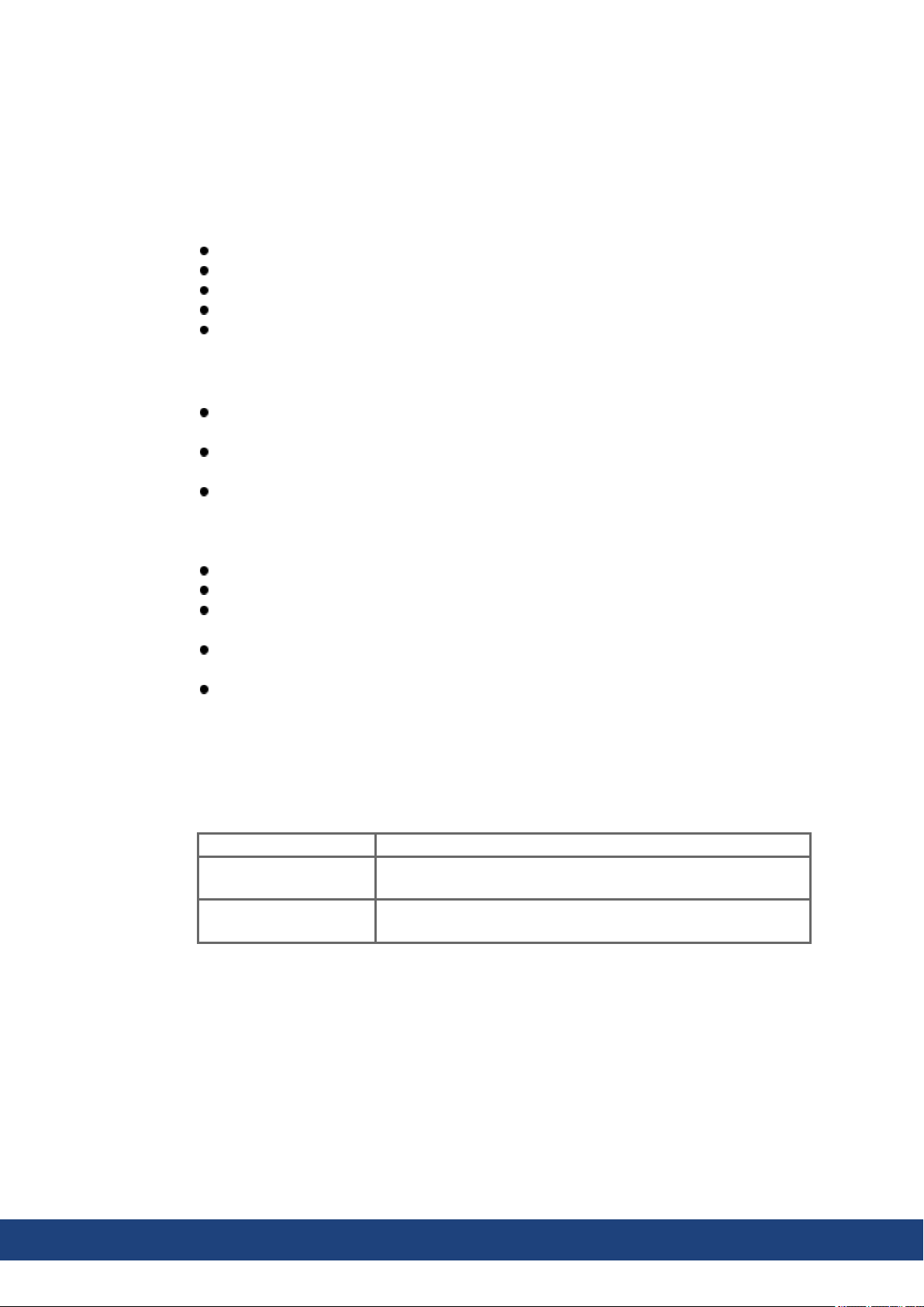
This document, the AKD®2G Installation Manual ("Instructions Manual" according to EC
Machinery Directive 2006/42/EU), describes the AKD®2G series of digital drives and
includes information needed to safely install an AKD2G.
This document is valid for AKD2G single axis drive or dual axis drive with 110V to 240V or
240V to 480V mains voltage.
Ouput stages: 3 A or 6 A or 12 A rated current
Programmability options: Base drive or Position Indexer drive
Connectivity options: analog, CANopen, EtherCAT, PROFINET, EtherNet/IP
I/O options: ExtendedI/O (X22), Feedback&EEO (X23)
Functional Safety Option: FS1 with STO; SIL2 PLd
A digital versionof this manual (pdf format) is available on the DVD included with yourdrive.
AKD2G information for use consist of:
Safety Notes: multi-languagedocument with safety information, part of product delivery
in Europe, printed on paper DIN A5.
Installation Manual: This document, describes the AKD2G series of digital drives and
includes information needed to safely install an AKD2G.
WorkBench Online Help: describes how to use your drive in common applications. It also
provides tips for maximizing your system performance with the AKD2G. The Online Help
includes the Parameter and Command Reference Guide which provides information for
the parameters and commands used to program the AKD2G.
CAN-BUS Communication: describes how to use your drive in CANopen applications.
EtherCAT Communication: describes how to use your drive in EtherCAT applications.
PROFINET Communication: describes how to use yourdrive in PROFINET applications
(available 2021).
EtherNet/IP Communication: describes how to use your drive in EtherNet/IP applications
(available 2021).
Accessories Manual: provides information for accessories like cables and regen res-
istors used with AKD2G. Regional variants of this manual exist.
All documents can be downloadedfrom the Kollmorgen website www.kollmorgen.com.
2.2 Using the PDF Format
This document includes several features for ease of navigation
Cross References Table of contents and index include active cross references.
Table of contents and
index
Page/chapter numbers
in the text
Lines are active cross references. Click on the line and the appropriate pageis accessed.
Page/chapternumbers with cross references are active links.
10 Kollmorgen | kdn.kollmorgen.com | July 2020
Page 11
2.3 Symbols Used
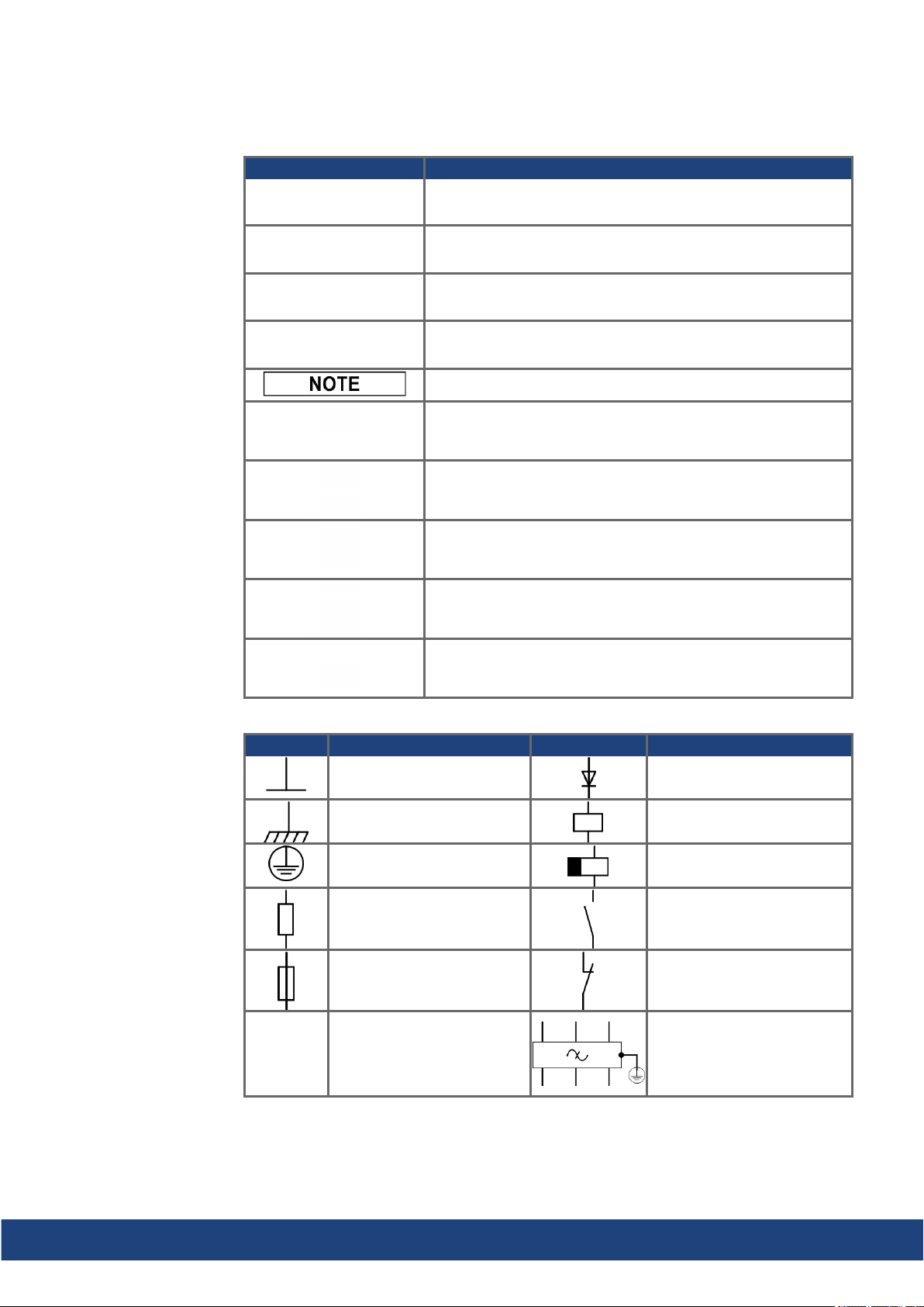
Warning Symbols
AKD2G-S Installation Manual, Safety 1 | 2 General
Symbol Indication
Indicates a hazardous situation which, if not avoided, will result
in death or serious injury.
Indicates a hazardous situation which, if not avoided, could result in death or serious injury.
Indicates a hazardous situation which, if not avoided, could result in minoror moderate injury.
Indicates situations which, if not avoided, could result in property damage.
This symbol indicates important notes.
Warning of a danger (general). The type of danger is specified
by the text next to the symbol.
Warning of danger from electricity and its effects.
Warning of danger from hot surface.
Warning of danger from suspendedloads.
Warning of danger from automatic start.
Drawing symbols
Symbol Description Symbol Description
Signal ground Diode
Chassis ground Relay
Protective earth Relay switch off delayed
Resistor Normally open contact
Fuse Normally closed contact
State-of-the-art firewall EMC filter
Kollmorgen | kdn.kollmorgen.com | July 2020 11
Page 12
AKD2G-S Installation Manual, Safety 1 | 2 General
2.4 Abbreviations Used
Abbreviations related to functional safety (➜ # 135).
Abbreviation Meaning
(➜ # 53) "see page 53" in this document
➜ xyz "see chapter xyz" in this document
Ω Ohms
A#, AXIS# A# or AXIS# are placeholders for the axis number. Used with parameters or
signal names
AGND Analogground
AquadB In quadrature output, used for incremental encoder emulation
AMSL Above mean sea level
Axis Depends on context, either one AKD2G output stage or one load axis of the
full motion system.
CAT Category
CE Communité Européenne
COM Serial interface for a personal computer
DGND Digital ground
EEPROM Electrically erasable programmable memory
EEO EmulatedEncoder Output
EMC Electromagnetic compatibility
EMF Electromagnetic force
FS1, FS2, FS3 Functional Safety Option 1, 2, 3
FSoE Fail safe over EtherCAT
KAS Kollmorgen Automation Suite
KAS IDE Setup software (Kollmorgen AutomationSuite Integrated Development
Environment)
KDN Kollmorgen Developer Network
LED Light-emitting diode
LSB Low significant byte (or bit)
MSB Most significant byte (or bit)
NI Zero pulse
OSSD Output Signal Switching Device
PE Protective earth
PELV Protective Extra Low Voltage
PLC Programmable logic control
PWM Pulse-width modulation
RAM Random access memory (volatile memory)
RBrake/RB Regen resistor (also called a brake resistor)
RBext External regenresistor
RBint Internal regen resistor
RCD Residual current device
RES Resolver
S1 Continuous operation
tbd To be determined (in process)
VAC Volts, alternating current
VDC Volts, direct current
12 Kollmorgen | kdn.kollmorgen.com | July 2020
Page 13

AKD2G-S Installation Manual, Safety 1 | 3 Product Safety
3 Product Safety
3.1 You should pay attention to this 14
3.2 Use as Directed 16
3.3 Prohibited Use 17
3.4 Warning note labels 17
3.5 Shock-hazard Protection 18
3.6 Stop / Emergency Stop / Emergency Off 19
Kollmorgen | kdn.kollmorgen.com | July 2020 13
Page 14

AKD2G-S Installation Manual, Safety 1 | 3 Product Safety
3.1 You should pay attention to this
This section helps to recognize risks and avoid dangers to people andobjects.
Specialist staff required!
Only properly qualified personnel are permitted to perform such tasks as transport, installation and setup. Qualified specialist staff are persons with expertise in transport, installation,
assembly, commissioning and operation of electrotechnical equipment.
Transport, storage, unpacking: only by personnel with knowledge of handling electrostatically sensitive components.
Mechanical installation: only by personnel with mechanical expertise.
Electrical installation: only by personnel with expertise in electrical engineering.
Basic tests / setup: only by personnel with expertise in electrical engineering and drive
technology.
The qualified personnel must know and observe ISO 12100 / IEC 60364 / IEC 60664 and
national accident prevention regulations.
Read the documentation!
Read the available documentationbefore installationand commissioning. Improperhandling
of the devices can cause harm to people or damage to property. The operatorof systems
using the drive system must ensure that all personnel who work with the drive read and understand the manual before using the drive.
Check Hardware Revision!
Check the Hardware Revision Number of the product (see product label). This number is the
link between your product and the manual. The product Hardware Revision Number must
match the HardwareRevision Number on the cover page of the manual.
Pay attention to the technical data!
Adhere to the technical data and the specifications on connection conditions. If permissible
voltage values or current values are exceeded, the devices can be damaged. Unsuitable
motor orwrong wiring will damage the system components. Check the combination of drive
andmotor. Compare the ratedvoltageand current of the units.
Perform a risk assessment!
The manufacturer of the machine must generate a risk assessment for the machine, and take
appropriate measures to ensure that unforeseen movements cannot cause injury or damage
to any person or property. Additional requirements on specialist staff may also result from the
risk assessment.
Automatic restart
The drive might restart automatically after power on, voltage dip or interruption of the supply
voltage, dependingon the parameter setting. Risk of death or serious injury for humans working in the machine.
If the parameterAXIS#.ENDEFAULT is set to 1, then place a warning sign to the machine
(Warning: Automatic Restart at Power On) and ensure, that power on is not possible, while
humans are in a dangerous zone of the machine. In case of using an undervoltage protection
device, you must observe EN 60204-1:2006 chapter 7.5 .
ATTENTION: The drive is ready to operate with pre-configured STO function.
14 Kollmorgen | kdn.kollmorgen.com | July 2020
Page 15

AKD2G-S Installation Manual, Safety 1 | 3 Product Safety
Observe electrostatically sensitive components!
The devices contain electrostatically sensitive components which may be damaged by incorrect handling. Electrostatically discharge your body before touching the device. Avoid contact with highly insulating materials (artificial fabrics, plastic film etc.). Place the device on a
conductive surface.
Hot surface!
Drives may have hot surfaces during operation. The housing can reach temperatures above
80°C. Risk of minor burns! Measure the temperature, andwait until the housing has cooled
down below 40 °C before touching it.
Earthing!
It is vital that you ensure that the drive is safely earthed to the PE (protective earth)busbar in
the switch cabinet. Risk of electric shock. Without low-resistance earthing no personal protection can be guaranteed.
Leakage Current!
Since the leakage current to PE is more than 3.5 mA, in compliance with IEC61800-5-1the
PE connection must eitherbe doubled or a connecting cable with a cross-section >10 mm²
must be used. Deviating measures according to regional standards might be possible.
High voltages!
The equipment produces high electric voltages up to 900 V. Lethal danger exists at live parts
of the device. Do not open or touch the equipment during operation. Keep all covers and cabinet doors closed. Built-in protection measures such as insulation or shielding may not be
removed. Work on the electrical installation may only be performedby trainedand qualified
personnel, in compliance with the regulations for safety at work, and only with switchedoff
mains supply, and securedagainst restart.
Never undo any electrical connections to the drive while it is live. There is a danger of electrical arcing with damage to contacts and personal injury. Wait at least 5 minutes after disconnecting the drive from the main supply power before touching potentially live sections of
the equipment (such as contacts) or removing any connections.
Always measure the voltage in the DC bus link and wait until the voltage is below 50 V
before handling components.
Functional Safety!
The assessment of the safety functions according to EN13849or EN 62061must finally be
done by the user.
Reinforced Insulation
Thermal sensors, motor holding brakes and feedback systems built into the connected motor
must have reinforced insulation(according to IEC61800-5-1) against system components
with powervoltage, according to the required application test voltage. All Kollmorgen components meet these requirements.
Never modify the drive!
It is not allowed to modify the drive hardwarewithout permission by the manufacturer. Opening the housing causes loss of warranty.
Kollmorgen | kdn.kollmorgen.com | July 2020 15
Page 16
AKD2G-S Installation Manual, Safety 1 | 3 Product Safety
3.2 Use as Directed
The AKD2G drives are exclusively intended for drivingsuitablesynchronous servomotors
with closed-loop control of torque, speed, and/or position.
AKD2G are components that are built into electrical plants or machines and can only be operated as integral components of these plants or machines. The manufacturer of the machine
used with a drive must generate a risk assessment for the machine. When the drives are built
into machines or plant, the drive must not be used until it has beenestablished that the
machine or plant fulfills the requirements of the regional directives.
Cabinet and wiring
Drives must only be operated in a closed control cabinet suitable for the ambient conditions
(➜ # 31). Ventilationor cooling may be necessary to keep the temperature within the cabinet
below 40°C or 60°C if using extended range operation with derating.
Use only copper conductors for wiring. The conductor cross-sections can be derived from the
standard IEC 60204 (alternatively for AWG cross-sections: NEC Table 310-16, 75°C
column).
Power supply
The drives can be supplied by 1, 2 or 3 phase (TN-S or TT) or DC industrial supply networks.
Drives in the AKD2G series can be suppliedas follows:
AKD2G-Sxx-6Vxx:
1, 2 or 3 phase industrial supply networks (not more than10 kA symmetrical rated current
at 120V and 240V) or DC supply.
AKD2G-Sxx-7Vxx:
3 phase industrial supply networks (not more than 10kA symmetrical ratedcurrent at
240V, 400V and 480V) or DC supply.
Connection to other voltage types of supply networks is possible with an additional isolating
transformer.
Repeated overvoltages betweenphases (L1, L2, L3) and the housing of the drive must not
exceed 1000V peak. In accordance with IEC61800, voltage spikes (< 50µs) between
phases must not exceed1000V. Voltage spikes (<50µs) between a phase and the housing
must not exceed 2000V.
Motor voltage rating
The rated voltage of the motors must be at least as high as the DC bus link voltage dividedby
√2 produced by the drive (U
nMotor
>=UDC/√2).
Functional Safety
Beta drives: Safety functions are neither approved norcertified yet. Do not use this functionality in applications with functional safety request until further notice.
The network, to which the drive is connected, must be secured according to state-of-theart information technology security requirements.
The userIT specialists shall analyze whetherfurther security requirements are applicableto ensure functional safety.
Review the chapter"Use as Directed" in the Functional Safety section (➜ # 133) before
using safety functionality.
16 Kollmorgen | kdn.kollmorgen.com | July 2020
Page 17

3.3 Prohibited Use
Otheruse than that described in chapter “Use as directed” is not intended and can lead to personnel injuries andequipment damage. The drive may not be used with a machine that does
not comply with appropriate national directives or standards. The use of the drive in the following environments is also prohibited:
potentially explosive areas
environments with corrosive and/or electrically conductive acids, alkaline solutions, oils,
vapors, dusts
ships or offshore applications
The drive must not be connected directly to the Internet. If the network, to which the drive is
connected, is not secured according to state-of-the-art information technology, this could be
a functional safety risk.
3.4 Warning note labels
3.4.1 Notes placed on the product
AKD2G-S Installation Manual, Safety 1 | 3 Product Safety
Wait 5 minutes
after removing power
before servicing.
3.4.2 Adhesive label in the package
Follow the instructions given on the adhesive labels in the package.
If a warning note label is damaged, it must be replaced immediately.
Kollmorgen | kdn.kollmorgen.com | July 2020 17
Page 18
AKD2G-S Installation Manual, Safety 1 | 3 Product Safety
3.5 Shock-hazard Protection
3.5.1 Leakage current
Leakagecurrent via the PE conductor results from the combination of equipment and cable
leakage currents. The leakage current frequency patternincludes a number of frequencies,
whereby the residual-current circuit breakers definitively evaluate the 50 Hz current. For this
reason, the leakagecurrent cannot be measured using a conventional multimeter. Contact
ourapplication department for help to calculate the leakage current in your application.
Since the leakage current to PE is more than 3.5 mA, in compliance with IEC61800-5-1the
PE connection must eitherbe doubled or a connecting cable with a cross-section >10 mm²
must be used. Use the PE terminal and the PE connection screws in orderto fulfill this
requirement.
The following measures can be used to minimize leakagecurrents:
Reduce the length of the engine cable.
Use low capacitance motor cables (➜ # 49).
3.5.2 Residual current protective device (RCD)
In conformity with IEC 60364-4-41 – Regulations for installationand IEC 60204– Electrical
equipment of machinery, residual current protective devices (RCDs) can be used provided
the requisite regulations arecomplied with. The AKD2G is a 3-phase system with a B6
bridge. Therefore, RCDs which aresensitive to all currents must be used in order to detect
any DC fault current.
Rated residual currents in the RCDs:
10 to 30 mA Protection against "indirect contact" (personal fire protection) for stationary
50 to 300 mA Protection against "indirect contact" (personal fire protection) for stationary
Recommendation: In order to protect against direct contact (with motor cables shorter than
5 m) Kollmorgen recommends that each drive be protected individually using a 30 mA RCD
which is sensitive to all currents.
If you use a selective RCD, the more intelligent evaluation process will prevent spurious trippingof the RCD.
3.5.3 Isolating transformers
When protection against indirect contact is absolutely essential despite a higher leakage current, or when an alternative form of shock-hazard protection is sought, the AKD2G can also
be operated by using an isolating transformer. A ground-leakage monitor can be used to monitor for short circuits.
Keep the length of wiring between the transformer and the drive as short as possible.
andmobile equipment, as well as for "direct contact".
equipment
18 Kollmorgen | kdn.kollmorgen.com | July 2020
Page 19
AKD2G-S Installation Manual, Safety 1 | 3 Product Safety
3.6 Stop / Emergency Stop / Emergency Off
The control functions Stop, Emergency Stop and Emergency Off are defined by IEC60204.
Notes for functional safety aspects of these functions can be foundin ISO13849 and
IEC62061.
The parameter AXIS#.DISMODE must be set to implement the different stop categories for
software disabling. Consult the WorkBench Online Help for configuring the parameter.
Vertical load could fall!
Serious injury could result when the load is not properly blocked. The internal brake function
does not ensure functional safety.
Functional safety, e.g. with hanging load (vertical axes), requires an additional brake,
controlled e.g. from the other axis or externally from a safety controller. The brakes can
be mappedto an axis with WorkBench.
The Hardware Enable does not initiate a controlledstop but switches off the power stage
immediately.
Set parameter AXIS#.MOTOR.BRAKEIMM to 1 with vertical axes, to apply the brake
immediately after faults or Hardware Disable.
Risk assessment of the application determines the necessary measures.
3.6.1 Stop
The stop function shuts down the machine in normal operation. The stop function is defined
by IEC 60204.
The Stop Category must be determinedby a risk evaluation of the machine.
Stop function must have priority over assigned start functions. The following stop categories
aredefined:
Stop Category 0
Shut-down by immediate switching-off the energy supply to the drive machinery (this is an
uncontrolled shut-down).
For stop without using safety functions like STO, set AXIS#.DISMODE to 0.
The safety function STO stops the drive as required by Stop Category 0 (IEC 62061).
Stop Category 1
A controlled shut-down, whereby the energy supply to the drive machinery is maintainedto
perform the shut-down, and the energy supply is only interrupted when the shut-down has
been completed.
For stop without using safety functions like SS1, set AXIS#.DISMODE to 2.
The safety function SS1 stops the drive as required by Stop Category 1 (IEC 62061).
Stop Category 2
A controlled shut-down, whereby the energy supply to the drive machinery is maintained.
This category shall be realizedwith a safety function like SS2. Safety function SS2 stops the
drive as required by Stop Category 2 (IEC 62061).
Stop Category 0 and Stop Category 1 stops must be operableindependently of the operating
mode, whereby a Category 0 stop must have priority.
If necessary, provision must be made for the connection of protective devices and lock-outs.
If applicable, the stop function must signal its status to the control logic. A reset of the stop
function must not create a hazardous situation.
Kollmorgen | kdn.kollmorgen.com | July 2020 19
Page 20
AKD2G-S Installation Manual, Safety 1 | 3 Product Safety
3.6.2 Emergency Stop
The Emergency Stop function is used for the fastest possible shutdown of the machine in a
dangerous situation. The Emergency Stop function is defined by IEC 60204. Principles of
emergency stop devices and functional aspects are defined in ISO 13850.
The Emergency Stop function will be triggered by the manual actions of a single person. It
must be fully functional and available at all times. The user must understand instantly how to
operate this mechanism (without consulting references or instructions).
The Stop Category for the Emergency Stop must be determinedby a risk evaluation of the
machine.
In addition to the requirements for stop, the Emergency Stop must fulfill the following requirements:
Emergency Stop must have priority over all other functions andcontrols in all operating
modes.
The energy supply to any drive machinery that could cause dangerous situations must be
switched off as fast as possible, without causing any further hazards (Stop Category 0)
or must be controlledin such a way, that any movement that causes danger, is stopped
as fast as possible (Stop Category 1).
The reset must not initiate a restart.
3.6.3 Emergency Off
The Emergency Off function is used to switch-off the electrical power supply of the machine.
This is done to prevent users from any risk from electrical energy (for example electrical
impact). Functional aspects for Emergency Off aredefined in IEC 60364-5-53.
The Emergency Off function will be triggeredby the manual actions of a single person.
The result of a risk evaluation of the machine determines the necessity for an Emergency
Off function.
Emergency Off is doneby switching off the supply energy by electro-mechanical switching
devices. This results in a category 0 stop. If this stop category is not possible in the application, then the Emergency Off function must be replaced by other measures (for example by
protection against direct touching).
20 Kollmorgen | kdn.kollmorgen.com | July 2020
Page 21

AKD2G-S Installation Manual, Safety 1 | 4 Product life cycle handling
4 Product life cycle handling
4.1 Transport 22
4.2 Packaging 22
4.3 Storage 22
4.4 Installation, setup and normal operation 23
4.5 Decommissioning 23
4.6 Maintenance and cleaning 23
4.7 Disassembly 23
4.8 System Repair 24
4.9 Disposal 24
Kollmorgen | kdn.kollmorgen.com | July 2020 21
Page 22
AKD2G-S Installation Manual, Safety 1 | 4 Product life cycle handling
4.1 Transport
Transport the AKD2G in accordance with IEC 61800-2 as follows:
Transport only by qualified personnel in the manufacturer’s original recyclablepackaging.
NOTICE: Avoid shocks while transporting.
Vibration/Shock: AKD2G is tested for environmental class 2M1 of IEC 60721-3-2.
Store at or below maximum stacking height 8 cartons (see "Storage" (➜ # 22))
Transport only within specified temperature ranges:
-25to +70 °C, max. rate of change 20 K/hour, class 2K3.
Transport only within specified humidity:
max. 95% relative humidity at +40°C, no condensation, class 2K3.
The drives contain electrostatically sensitive components that can be damaged by incorrect
handling. Electrostatically discharge yourself before touching the drive. Avoid contact with
highly insulating materials, such as artificial fabrics and plastic films. Place the drive on a
conductive surface.
If the packagingis damaged, check the unit for visible damage. Inform the shipperand the
manufacturer of any damage to the package or product.
4.2 Packaging
4.3 Storage
The AKD2G packaging consists of recyclable cardboard with inserts and a label on the outside of the box.
Model
AKD2G-Sxx-6V03 to 6V12 158x 394 x 292 4.2
AKD2G-Sxx-7V03 to 7V12 158x 394 x 292 4.3
Mating connectors are not included in the package of a standarddrive.
Mating connectors are included when the drive is orderedwith accessories (append “-A”to
the model number).
Store the AKD2G in accordance with IEC 61800-2 as follows:
Store only in the manufacturer’s original recyclable packaging.
Store at or below maximum stacking height 8 cartons.
Store only within specified temperature ranges: -25to +55 °C, max.rate of change
20K/hour, class 1K4.
Storage only within specified humidity: 5 to 95% relative humidity, no condensation, class
1K3.
Store in accordance with the following duration requirements:
Less than 1 year: without restriction.
More than 1 year: capacitors must be re-formed before setting up and operating the
drive. Re-forming procedures aredescribed in the KDN (Forming).
Package
(mm) HxWxL
Total Weight
(kg)
22 Kollmorgen | kdn.kollmorgen.com | July 2020
Page 23
AKD2G-S Installation Manual, Safety 1 | 4 Product life cycle handling
4.4 Installation, setup and normal operation
Installation andsetup information are given in this manual:
Mechanical installation (➜ # 42)
Electrical installation(➜ # 45)
Setup (➜ # 115)
Normal operation tested for environmental class 3K3 according to IEC 61800-2 (➜ # 31).
The manufacturer of the machine defines the necessary enduser expertise based onthe risk
assessment for the machine and describes the requirements for normal operation based on
the application.
4.5 Decommissioning
Only professional staff who arequalified in electrical engineering are allowed to decommission parts of the system.
DANGER: Lethal Voltages!
There is a dangerof serious personal injury or death by electrical shock or electrical arcing.
Switch off the main switch of the switchgear cabinet.
Securethe system against restarting.
Block the main switch.
Wait at least 5 minutes after disconnecting.
4.6 Maintenance and cleaning
The device does not require maintenance, it shouldbe inspected once a year by professional
staff.
Do not immerse or spray the device. Avoid that liquid enters the device. The inside of the
unit can only be cleaned by the manufacturer. Opening the device voids the warranty.
To clean the device exterior:
1. Decommission the device (see chapter 4.5 "Decommissioning").
2. Casing: Clean with Isopropanol or similar cleaning solution.
Caution : Highly Flammable! Risk of injury by explosionand fire.
Observe the safety notes given on the cleaning liquidpackage.
Wait at least 30 minutes after cleaningbefore putting the device back into operation.
3. Protective grill on fan: Clean with a dry brush.
4.7 Disassembly
Only professional staff who arequalified in electrical engineering are allowed to disassemble
parts of the system.
1. Decommission the device (see chapter 4.5 "Decommissioning").
2. Check temperature.
CAUTION: High Temperature! Risk of minor burns. During operation, the heat sink of
the drive may reach temperatures above 80°C (176°F). Before touching the device,
check the temperature andwait until it has cooled below 40°C (104°F).
3. Remove the connectors. Disconnect the potential earth connection last.
4. Demount: loosen the fastening screws. Remove the device.
Kollmorgen | kdn.kollmorgen.com | July 2020 23
Page 24
AKD2G-S Installation Manual, Safety 1 | 4 Product life cycle handling
4.8 System Repair
Only professional staff who arequalified in electrical engineering are allowed to exchange
parts of the drive system.
CAUTION: Automatic Start! During replacement work a combination of hazards and mul-
tiple episodes may occur.
Work on the electrical installation may only be performed by trained andqualified personnel, in compliance with the regulations for safety at work, and only with use of prescribed personal safety equipment.
Exchange of the device
Only the manufacturer can repair the device. Opening the device voids the warranty.
1. Decommission the device (see chapter 4.5 "Decommissioning").
2. Demount the device (see chapter 4.7 "Disassembly").
3. Send the device to the manufacturer.
4. Install a new device as described in the InstallationManual.
5. Setup the system as described in the Installation Manual.
Exchange of other drive system parts
If parts of the drive system (for example cables) must be replaced, proceed as follows:
4.9 Disposal
1. Decommission the device (see chapter 4.5 "Decommissioning").
2. Exchange the parts.
3. Check all connections for correct fastening.
4. Setup the system as described in the Installation Manual.
To dispose the unit properly, contact a certified electronic scrap disposal merchant.
In accordance with the WEEE-2012/19/EU guideline and similar, the manufacturer accepts
returns of old devices and accessories for professional disposal. Transport costs are the
responsibility of the sender.
Contact Kollmorgen andclarify the logistics.
Send the devices in the original packaging to the manufacturer address:
North America South America
KOLLMORGEN
201West Rock Road
Radford, VA 24141, USA
Europe Asia
KOLLMORGEN Europe GmbH
Pempelfurtstr. 1
40880 Ratingen, Germany
KOLLMORGEN
AvenidaJoão Paulo Ablas, 2970
Jardim da Glória, Cotia – SP
CEP 06711-250, Brazil
KOLLMORGEN
Room 302, Building 5, Lihpao Plaza,
88 Shenbin Road, MinhangDistrict,
Shanghai, China.
24 Kollmorgen | kdn.kollmorgen.com | July 2020
Page 25

AKD2G-S Installation Manual, Safety 1 | 5 Package
5 Package
5.1 Package Supplied 26
5.2 Nameplate 26
5.3 Part Number Scheme 27
Kollmorgen | kdn.kollmorgen.com | July 2020 25
Page 26
AKD2G-S Installation Manual, Safety 1 | 5 Package
5.1 Package Supplied
When a standard drive from the AKD2G series is delivered, the following items areincluded
in the drive package:
AKD2G
Printedcopy of AKD®2G Safety Notes.
DVD with WorkBench setup software .
Panel safety label
ATTENTION: Drive is ready to operate with pre-configured STO function.
Mating connectors are not included in the package of a standarddrive.
Mating connectors are included when the drive is orderedwith accessories (append “-A”to
the model number).
Mating connectors listed below are never deliveredwith the drive. These matingconnectors
areusually part of the cables:
Motor mating connector (X1, X2),
SubD (X23, X41) for Feedback,
RJ25 (X13, X14) for CAN Bus, and
RJ45 (X11, X12, X20) for Service and EtherNet Fieldbus.
Accessories sold separately
Accessories must be ordered separately if required, see regional Accessories Manual.
5.2 Nameplate
EMC filters for mains supply voltage, categories C2 or C3.
External regenresistor.
Mating connector kits.
Motor mating connector.
Hybrid cable. Assembled hybridmotor cables are available for all regions.
Motor cable. Assembled motor cables are available for all regions.
Feedback cable. Assembled feedback cables areavailable for all regions.
SFA (Smart Feedback Adapter) .
SDB Module (Safe Dynamic Brake Module).
EtherNet service cable.
A nameplate is attached to the side of the drive. The picture below is similar to the nameplate
on the device.
26 Kollmorgen | kdn.kollmorgen.com | July 2020
Page 27

5.3 Part Number Scheme
Use the part numberscheme for product identification only, not for the order process,
because not all combinations of features are possible.
Mating connectors are not included in the package of a standarddrive.
Mating connectors are included when the drive is orderedwith accessories (append “-A”
to the model number).
Mating connectors X1, X2, RJ25, RJ45, SubD arepart of the used cables always.
AKD2G-S Installation Manual, Safety 1 | 5 Package
Example AKD2G-SPE-7V06S-A1IO-0000
AKD2G IP20 housing, position indexer, EtherCAT, 240 V to 480 V mains supply, 6 A rated
current, single axis, Plattform Revision A, dual channel STO SIL2 PLd, with additional I/O
connector X22, uncoated, no mating connectors.
Example AKD2G-SPE-6V03D-A1F3-A000-A
AKD2G IP20 housing, position indexer, EtherCAT, 120 V to 240 V mains supply, 2 x 3 A
rated current, dual axis, Plattform Revision A, dual channel STO SIL2 PLd, with all possible
connectors (X21 + X22 + X23), PCBs coated, with mating connectors.
Kollmorgen | kdn.kollmorgen.com | July 2020 27
Page 28

AKD2G-S Installation Manual, Safety 1 | 6 Technical description anddata
6 Technical description and data
6.1 The AKD2G Family of Digital Drives 29
6.2 Ambient Conditions, Ventilation, and Mounting Position 31
6.3 Mechanical Data 31
6.4 Performance Data 32
6.5 Electrical data 33
6.6 Electrical Motor Braking 37
6.7 LCD Display and Push-buttons (B1, B2) 39
6.8 SD Card Slot 41
28 Kollmorgen | kdn.kollmorgen.com | July 2020
Page 29
AKD2G-S Installation Manual, Safety 1 | 6 Technical description anddata
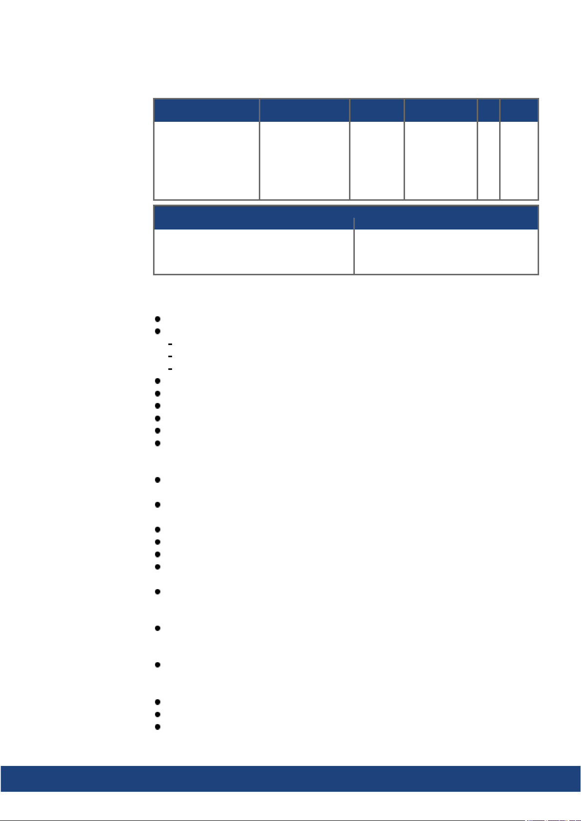
6.1 The AKD2G Family of Digital Drives
Available AKD2G-SP (Position Indexer) versions
Connectivity Rated Voltages Current Axis Rev
N-: Analog
C-: CANopen
E-: EtherCAT
P-*: PROFINET
I-*: EtherNet/IP
Connector Options
Single Axis Dual Axis
00: Basis (X21)
IO: Basis + X22
F3: Basis + X23
DX: Basis + X22+X23
* Available 2021
6V:
120/240VAC 1~
240VAC 3~
170/340 VDC
7V:
240/400/480VAC 3~
340/565/680 VDC
03: 3 A
06: 6 A
12: 12 A
00: Basis (X21, X22)
F3: Basis + X23
S-: Single
D-: Dual I1=I2
A 1: SIL2
Standard features
Single axis or dual axis in one housing
Supply voltages:
DC
AC single phase, split phase, three phase AC neutral or leg grounded
Single orgroupsupply, single or group mains fusing
EtherNet Fieldbus on board, TCP/IP service channel and Modbus on board
SFD3, HIPERFACE DSL motor feedback support on board
Support for many conventional motor feedback types
Step / Direction input on board
Encoder emulation on board
Use with synchronous servomotors, linear motors, and induction machines
Funct.
Safety
STO
Power section
Single orthree phase AC supply, 5% to 110% of rated AC voltage over 47 to 63 Hz. Connection to higher AC voltage mains only by using isolating transformer.
DC supply, voltage range 5% to 110% of rated DC voltage. Fusing to be providedby the
user.
Three phase bridge rectifier, integral soft-start circuit.
DC bus link voltage can be connected in parallel for power sharing.
Floating current sensors measureactual motorcurrent
Regenerative circuit with dynamic distribution of the generated power between several
drives on the same DC bus link circuit.
Internal regen resistor for all models, optional external regenresistor if required.
Functional Safety Options
FS1: STO; SIL2 PLd, command by I/O (➜ # 137).
Electrical safety
Appropriate insulation / creepagedistances and electrical isolation for safe electrical separation, per IEC 61800-5-1, between the powerinput / motor connections andthe signal
electronics.
Soft-start, over voltage detection, short-circuit protection, phase-loss detection.
Temperature monitoring of the drive and motor.
Electronic motor overloadprotection: foldback mechanism or optional fault response.
Kollmorgen | kdn.kollmorgen.com | July 2020 29
Page 30
AKD2G-S Installation Manual, Safety 1 | 6 Technical description anddata
Auxiliary supply voltage 24VDC
From an external, safety approved24 V ±10% power supply (PELV).
Parameter setting
Setup software WorkBench for setup by using TCP/IP.
Downloadcontrol parameterpackages by using CoE
Full digital control
Digital current loop(update 1.28 µs / command 62.5 µs)
Digital velocity loop(update period 62.5 µs)
Digital position loop (update period 250 µs)
Inputs/Outputs (X21/X22/X23)
2 programmable analog input (➜ # 105)
2 programmable analog output (➜ # 106)
12 programmable digital inputs (➜ # 107)
8 programmable digital outputs (➜ # 111)
6 programmable digital input/outputs (➜ # 111)
4 safe STO inputs (dual channel STO per axis) (➜ # 133)
Connector Options
IO: X22 connector with additional digital inputs andoutputs.
F3: X23 connector for conventional motor feedbacks (Resolver, SFD, Tamagawa Smart
Abs, Comcoder, 1Vp-p Sin-Cos encoders, incremental encoders, EnDAT 2.1/2.2 and
HIPERFACE).
DX: all possible connectors for extended I/O and feedback connections.
Customization
0000: uncoated PCBs, standard
0xxx: uncoatedPCBs, customized coding
A000: coated PCBs, standard
Axxx: coated PCBs, customized coding
Connectivity
Feedback inputs (➜ # 86)
Encoder emulation output (➜ # 92)
Digital Inputs/Outputs (➜ # 103)
Service Interface (➜ # 101)
Modbus Interface (➜ # 102)
CANopen (➜ # 98)
EtherNet Fieldbus interface (➜ # 95)
Accessories
SFA (Smart Feedback Adapter) (➜ # 91).
Hybrid motor cables, motor powercables, motor feedback cables.
External regenresistors.
For accessories referto your regional Accessories Manual.
30 Kollmorgen | kdn.kollmorgen.com | July 2020
Page 31
AKD2G-S Installation Manual, Safety 1 | 6 Technical description anddata
6.2 Ambient Conditions, Ventilation, and Mounting Position
Storage, Transport (➜ # 22)
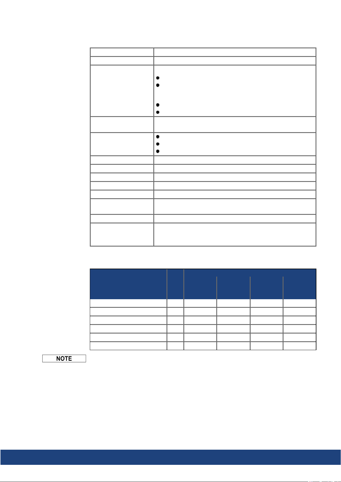
Normal operation Environmental class 3K3 according to IEC 61800-2
Surrounding temperature in operation
Humidity in operation Relative humidity 5 to 85%, no condensation, IEC 61800-2class
Site altitude Up to 1,000 m AMSL (above mean sea level): no restriction
Pollution level Pollution level 2 as per IEC 60664-1
Vibration Class 3M1 according to IEC 61800-2
Shock Class L according to IEC 61800-2
Drive protection IP 20 according to IEC 60529
Drive EMC immunity Increased immunity accordingto EN 61800-5-2
Mounting Vertical position, in a cabinet with protection of at least IP 54
Ventilation Built-in fan in all drive variants
Internal regen resistor used:
0 to +40 °C underrated conditions
+40 to +60 °C with output current derating 3 % per Kelvin
Internal regen resistor not used:
0 to +50 °C underrated conditions
+50 to +60 °C with output current derating 2 % per Kelvin
3K3
1,000 to 2,000 m AMSL: power derating 1.5%/100 m
Maximum altitude: 2,000m AMSL
Minimum cabinet size (WxHxD): 406 x 406x 254 mm
The drive shuts down in case of excessively high temperature in
the control cabinet. Make sure sufficient forced ventilationis suppliedwithin the control cabinet.
6.3 Mechanical Data
Weight kg 2.4 2.5 2.5 2.7
Width mm 76 76 75 75
Height, without connectors mm 235 235 272 272
Height, with connectors mm 303 303 340 340
Depth, without connectors mm 221 221 221 221
Depth, with connectors mm 232 232 232 232
Dimension Drawing see section Mechanical Installation (➜ # 42).
Units
6V03S,
6V06S,
6V12S
AKD2G-Sxx-
6V03D,
6V06D
7V03S,
7V06S
7V03D,
7V06D,
7V12S
Kollmorgen | kdn.kollmorgen.com | July 2020 31
Page 32
AKD2G-S Installation Manual, Safety 1 | 6 Technical description anddata
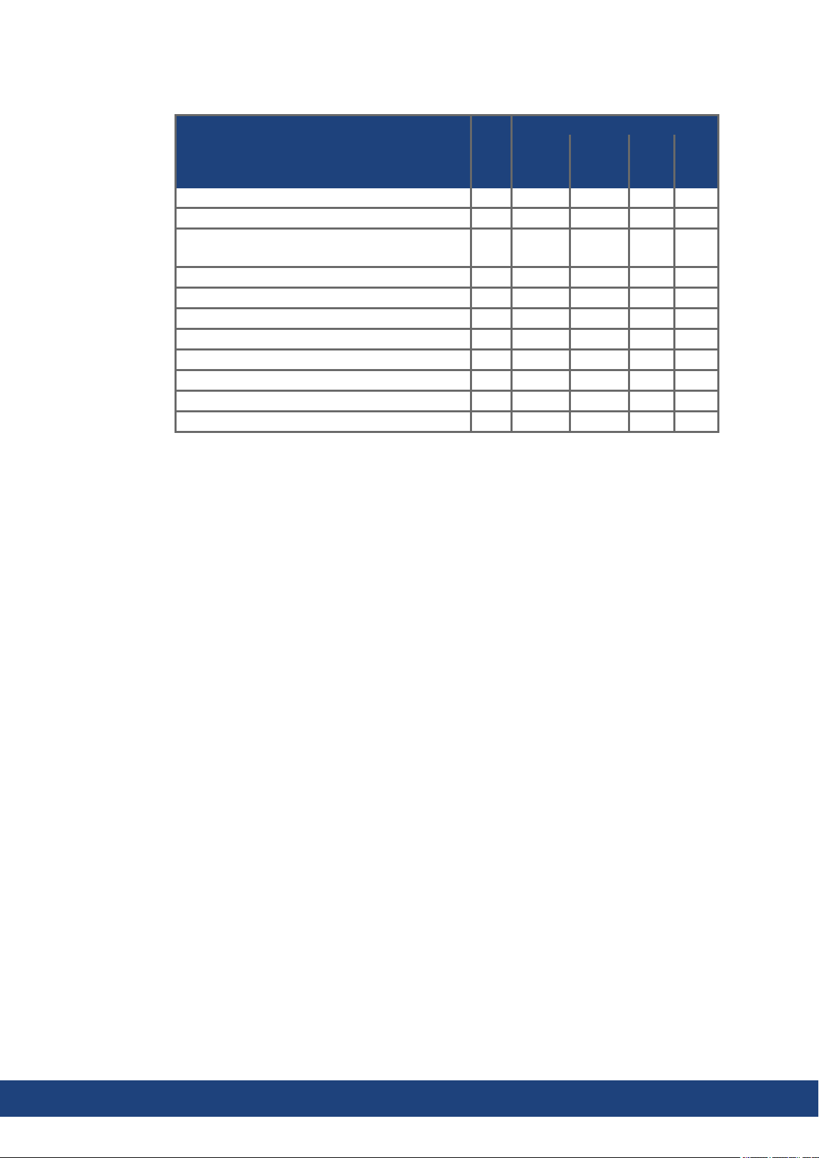
6.4 Performance Data
Performance Data Units
Normal PWM Switching Frequency (dynamic) kHz 15 11 9.8 9.8
High Load PWM Switching Frequency (dynamic) kHz 10.3 8.1 6.5 5.9
High Load Stalled PWM Switching Frequency
(dynamic)
Voltagerise speeddU/dt kV/µs 7.0 7.0 7.0 7.0
Current Loop Update Period µs 1.28* 1.28* 1.28* 1.28*
Velocity Loop Update Period µs 62.5 62.5 62.5 62.5
Position Loop Update Period µs 250 250 250 250
Current Loop Bandwidth Hz 3000 3000 3000 3000
Velocity Loop Bandwidth Hz 750 750 750 750
Position Loop Bandwidth Hz 350 350 350 350
Max. motor electrical frequency Hz 599 599 599 599
kHz 5.2 4.1 3.5 3.5
6V03S/D
6V06S/D
6V12S
AKD2G-Sxx-
7V03S/D
7V06S
7V06D 7V12S
* Control updates every 1.28 µs. Current command is updated every 62.5 µs.
32 Kollmorgen | kdn.kollmorgen.com | July 2020
Page 33
AKD2G-S Installation Manual, Safety 1 | 6 Technical description anddata
6.5 Electrical data
6.5.1 Single axis variants (S)
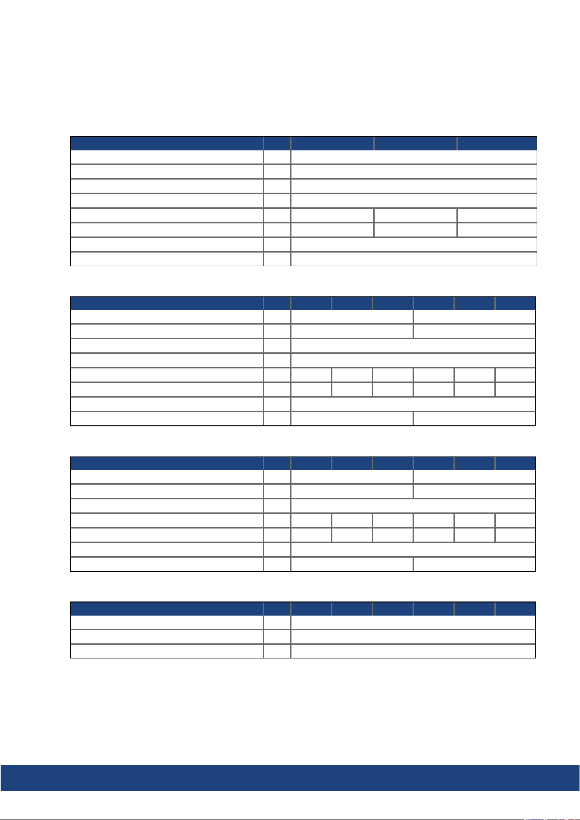
6.5.1.1 Mains supply data, 1 phase AC, type AKD2G-Sxx- (S)
Input data Units 6V03S 6V06S 6V12S
Operational supply voltage (line-line) VAC 12 to 265
Rated supply voltage VAC 240
Rated supply input frequency (±5%) Hz 50 to 60
Permitted switch on/off frequency 1/h 30
Rated input VA at 240 V kVA 1.0 1.7 3.1
Rated input current A 4.0 7.1 13
Max. inrush current A 10
Rated DC bus link voltage VDC 300
6.5.1.2 Mains supply data, 3 phase AC, type AKD2G-Sxx- (S)
Input data Units 6V03S 6V06S 6V12S 7V03S 7V06S 7V12S
Operational supply voltage (L1/L2/L3) VAC 12 to 265 24 to 525
Rated supply voltage VAC 240 480
Rated supply input frequency (±5%) Hz 50 to 60
Permitted switch on/off frequency 1/h 30
Rated input VA at 240 V (* at 480 V) kVA 1.3 2.2 4.0 2.7* 4.4* 7.2*
Rated input current A 3.2 5.3 9.7 3.2 5.3 8.7
Max. inrush current A 10
Rated DC bus link voltage VDC 310 620
6.5.1.3 Mains supply data, DC, type AKD2G-Sxx- (S)
Input data Units 6V03S 6V06S 6V12S 7V03S 7V06S 7V12S
Operational supply voltage (DC+/DC-) VDC 17 to 370 34 to 740
Rated supply voltage VDC 340 680
Permitted switch on/off frequency 1/h 30
Rated input powerat 340 V (* at 680 V) kW 0.62 1.25 2.5 1.25* 2.5* 5.0*
Rated input current A 2.0 4.0 8.0 2.0 4.0 8.0
Max. inrush current through AC input A 10
Rated DC bus link voltage VDC 340 680
6.5.1.4 Auxiliary voltage input data, 24VDC, type AKD2G-Sxx- (S)
Input data Units 6V03S 6V06S 6V12S 7V03S 7V06S 7V12S
Aux. voltage supply (PELV) VDC 24 V (±10%, check voltagedrop)
- control current without motor brake A < 1.0
- control current with one motorbrake A < 3.1
Kollmorgen | kdn.kollmorgen.com | July 2020 33
Page 34
AKD2G-S Installation Manual, Safety 1 | 6 Technical description anddata
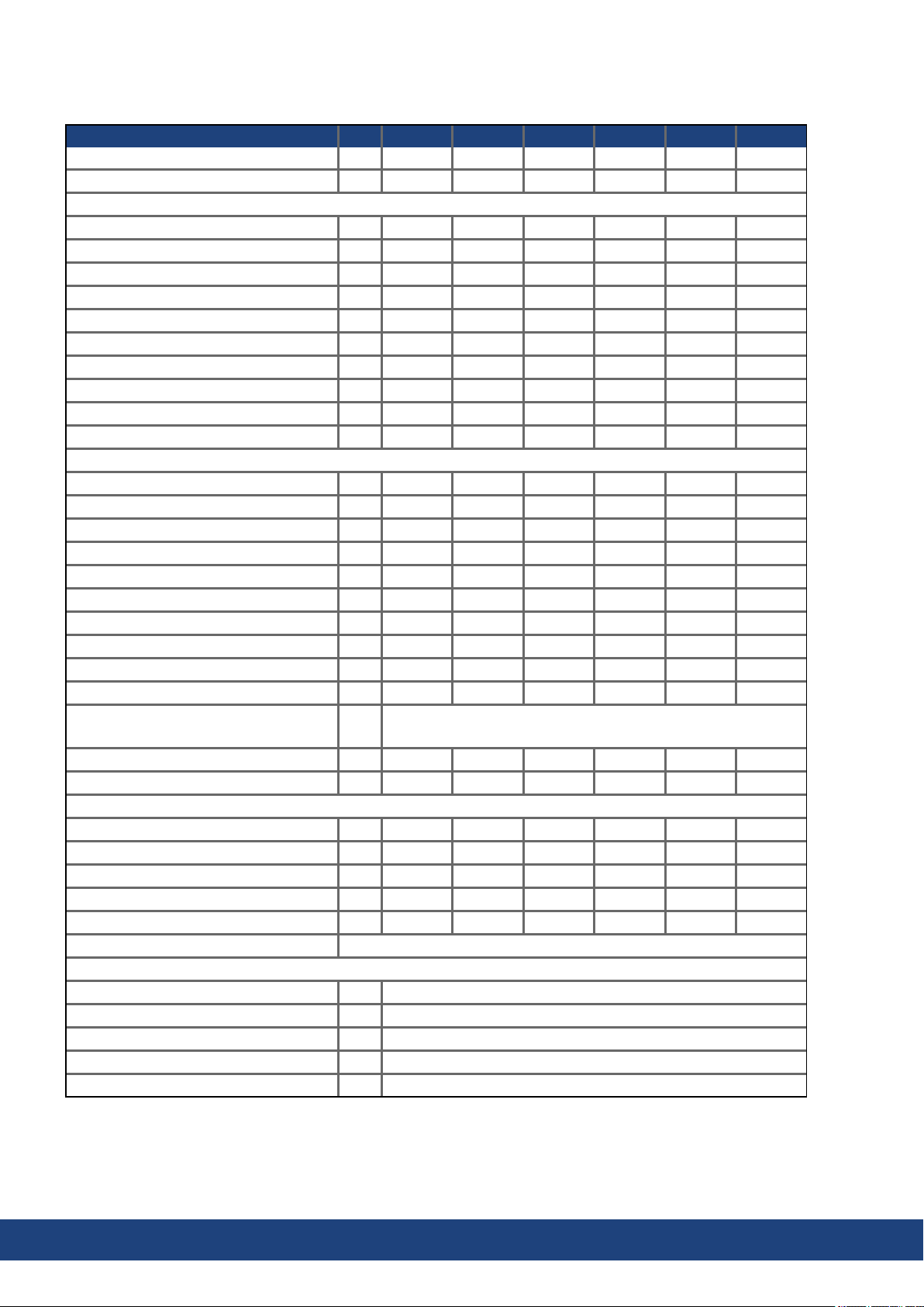
6.5.1.5 Output data, type AKD2G-Sxx- (S)
Units 6V03S 6V06S 6V12S 7V03S 7V06S 7V12S
Continuous output current ( ± 3%) Arms 3 6 12 3 6 12
Peak output current (for 5s, ±3%) Arms 9 18 30 9 18 30
Continuous motor shaft output power at rated input current
at 1 x 120VAC kW 0.22 0.44 0.875 - - at 1 x 240VAC kW 0.44 0.875 1.8 - - at 3 x 120VAC kW 0.31 0.625 1.25 - - at 3 x 240VAC kW 0.625 1.25 2.5 0.625 1.25 2.5
at 3 x 400VAC kW - - - 1.05 2.1 4.2
at 3 x 480VAC kW - - - 1.25 2.5 5.0
at 170 VDC kW 0.31 0.625 1.25 - - at 340 VDC kW 0.625 1.25 2.5 0.625 1.25 2.5
at 565 VDC kW - - - 1.05 2.1 4.2
at 680 VDC kW - - - 1.25 2.5 5.0
Peak output power (for 1 s)
at 1 x 120VAC kW 1.1 2.1 4.1 - - at 1 x 240VAC kW 2.1 4.2 6.3 - - at 3 x 120VAC kW 1.5 3 4.5 - - at 3 x 240VAC kW 3.0 6.0 9.0 3.0 6.0 10
at 3 x 400VAC kW - - - 5.0 10 16.5
at 3 x 480VAC kW - - - 6.0 12 20
at 170 VDC kW 1.5 3 4.5 - - at 340 VDC kW 3.0 6.0 9.0 3.0 6.0 10
at 565 VDC kW - - - 5.0 10 16.5
at 680 VDC kW - - - 6.0 12 20
Noise emission at 1 m,
dB(A) < 50 / 60
low/high speed fan
Thermal dissipation, disabled W 12 12 12 12 12 12
Thermal dissipationat rated current W 50 80 140 65 105 210
Motor inductance
minimum at 120 VAC mH 1.2 0.6 0.3 - - minimum at 240 VAC mH 2.4 1.2 0.6 3.1 1.5 1.1
minimum at 400 VAC mH - - - 5.1 2.6 1.8
minimum at 480 VAC mH - - - 6.1 3.1 2.1
maximum mH 240 120 60 610 310 210
Regeneration Braking (➜ # 37)
Brake output
Voltage(±10%) VDC 24
Voltagepower saving VDC 12 to 24
Output under current fault mA 100 (required for fault detection)
Output over current fault A 2.25 (requiredfor fault detection)
Output current, maximum A 2.1
34 Kollmorgen | kdn.kollmorgen.com | July 2020
Page 35
AKD2G-S Installation Manual, Safety 1 | 6 Technical description anddata
6.5.2 Dual axis variants (D: I1=I2)
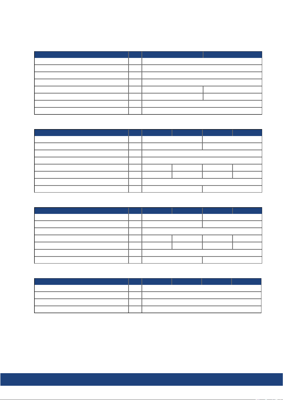
6.5.2.1 Mains supply data, 1 phase AC, type AKD2G-Sxx- (D)
Input data Units 6V03D 6V06D
Operational supply voltage (line-line) VAC 12 to 265
Rated supply voltage VAC 240
Rated supply input frequency (±5%) Hz 50 to 60
Permitted switch on/off frequency 1/h 30
Rated input VA at 240 V kVA 1.7 3.1
Rated input current A 7.2 13
Max. inrush current A 10
Rated DC bus link voltage VDC 300
6.5.2.2 Mains supply data, 3 phase AC, type AKD2G-Sxx- (D)
Input data Units 6V03D 6V06D 7V03D 7V06D
Operational supply voltage (L1/L2/L3) VAC 12 to 265 24 to 525
Rated supply voltage VAC 240 480
Rated supply input frequency (±5%) Hz 50 to 60
Permitted switch on/off frequency 1/h 30
Rated input VA at 240 V (* at 480 V) kVA 2.2 4.0 4.4* 7.2*
Rated input current A 5.3 9.7 5.3 8.7
Max. inrush current (at 240 V/480 V, 20°C) A 10
Rated DC bus link voltage VDC 310 620
6.5.2.3 Mains supply data, DC, type AKD2G-Sxx- (D)
Input data Units 6V03D 6V06D 7V03D 7V06D
Operational supply voltage (DC+/DC-) VDC 17 to 370 34 to 740
Rated supply voltage VDC 340 680
Permitted switch on/off frequency 1/h 30
Rated input powerat 340 V (* at 680 V) kW 1.25 2.5 2.5* 5*
Rated input current A 4 8 4 8
Max. inrush current through AC input A 10
Rated DC bus link voltage VDC 340 680
6.5.2.4 Auxiliary voltage input data, 24VDC, type AKD2G-Sxx- (D)
Input data Units 6V03D 6V06D 7V03D 7V06D
Aux. voltage supply (PELV) VDC 24 V (±10%, check voltagedrop)
- current without motor brake A <1
- control current with one motorbrake A <3.1
- control current with two motor brakes A <5.2
Kollmorgen | kdn.kollmorgen.com | July 2020 35
Page 36
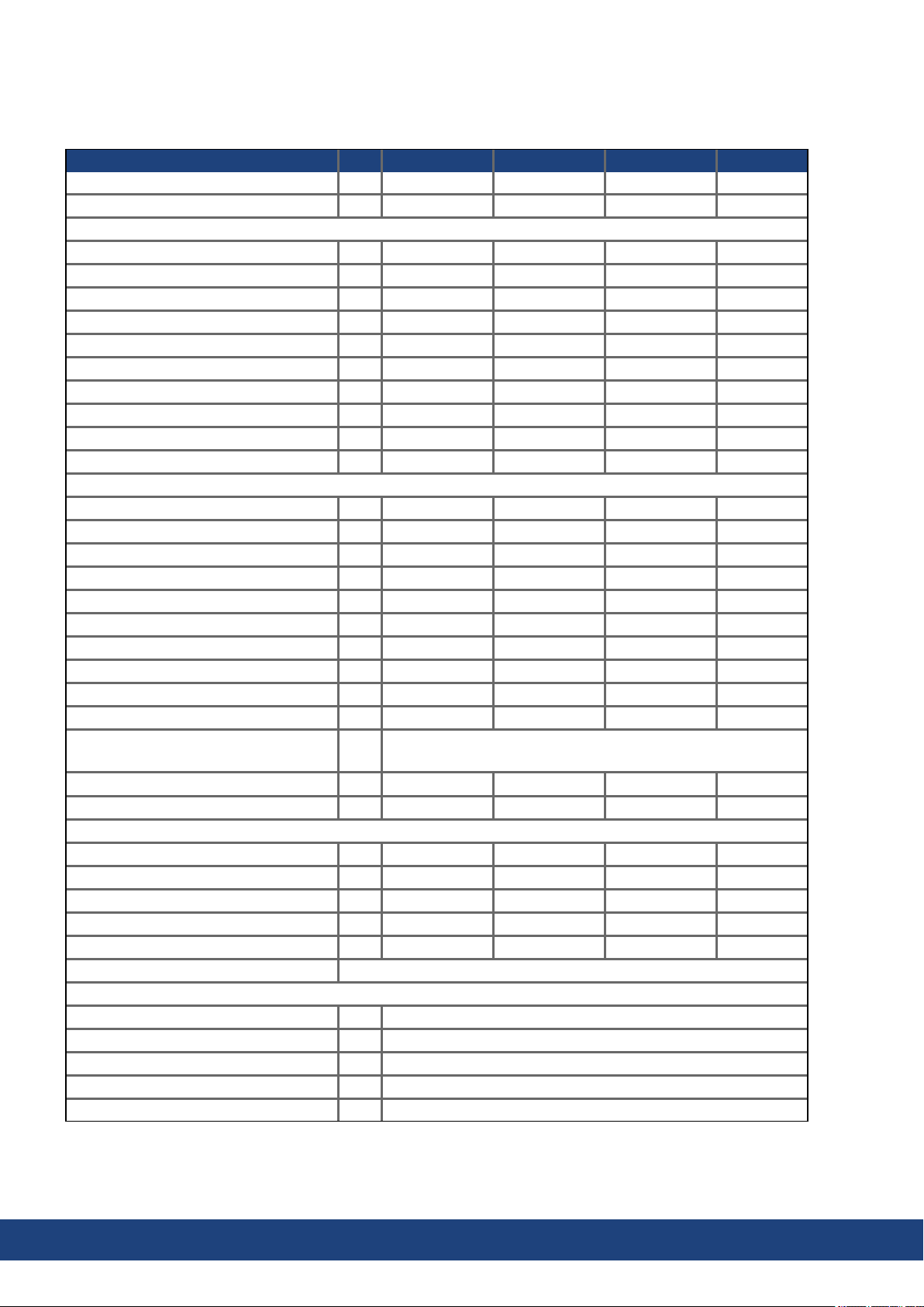
AKD2G-S Installation Manual, Safety 1 | 6 Technical description anddata
6.5.2.5 Output data, type AKD2G-Sxx- (D)
Drive current and power output values are listed for Axis1/Axis2.
Units 6V03D 6V06D 7V03D 7V06D
Continuous output current ( ± 3%) Arms 3/3 6/6 3/3 6/6
Peak output current (for 5s, ±3%) Arms 9/9 18/18 9/9 18/18
Continuous motor shaft output power at rated input current
at 1 x 120VAC kW 0.22/0.22 0.44/0.44 - at 1 x 240VAC kW 0.44/0.44 0.875/0.875 - at 3 x 120VAC kW 0.31/0.31 0.625/0.625 - at 3 x 240VAC kW 0.625/0.625 1.25/1.25 0.625/0.625 1.25/1.25
at 3 x 400VAC kW - - 1.05/1.05 2.1/2.1
at 3 x 480VAC kW - - 1.25/1.25 2.5/2.5
at 170 VDC kW 0.31/0.31 0.625/0.625 - at 340 VDC kW 0.625/0.625 1.25/1.25 0.625/0.625 1.25/1.25
at 565 VDC kW - - 1.05/1.05 2.1/2.1
at 680 VDC kW - - 1.25/1.25 2.5/2.5
Peak output power (for 1 s)
at 1 x 120VAC kW 1.1/1.1 2.1/2.1 - at 1 x 240VAC kW 2.1/2.1 4.2/4.2 - at 3 x 120VAC kW 1.5/1.5 3.0/3.0 - at 3 x 240VAC kW 3.0/3.0 6.0/6.0 3.0/3.0 6.0/6.0
at 3 x 400VAC kW - - 5.0/5.0 10/10
at 3 x 480VAC kW - - 6.0/6.0 12/12
at 170 VDC kW 1.5/1.5 3.0/3.0 - at 340 VDC kW 3.0/3.0 6.0/6.0 3.0/3.0 6.0/6.0
at 565 VDC kW - - 5.0/5.0 10/10
at 680 VDC kW - - 6.0/6.0 12/12
Noise emission at 1 m,
dB(A) < 50 / 60
low/high speed fan
Thermal dissipation, disabled W 15 15 15 15
Thermal dissipationat rated current W 90 150 120 210
Motor inductance
minimum at 120 VAC mH 1.2/1.2 0.6/0.6 - minimum at 240 VAC mH 2.4/2.4 1.2/1.2 3.1/3.1 1.9/1.9
minimum at 400 VAC mH - - 5.1/5.1 3.2/3.2
minimum at 480 VAC mH - - 6.1/6.1 3.8/3.8
maximum mH 240/240 120/120 610/610 380/380
Regeneration Braking (➜ # 37)
Brake output
Voltage(±10%) VDC 24
Voltagepower saving VDC 12 to 24
Output under current fault mA 100(required for fault detection)
Output over current fault A 2.25 (required for fault detection)
Output current, maximum A 2.1 per brake
36 Kollmorgen | kdn.kollmorgen.com | July 2020
Page 37
6.6 Electrical Motor Braking
6.6.1 Drive Dynamic Braking
Drive Dynamic brakingis a method to slow down a servo system by dissipating the mechanical energy driven by the motor back EMF.
Drive dynamic braking is not functional safe.
The AKD2G has a built in advanceddrive dynamic braking mode which operates fully in hardware. When activated, the drive powers the motor terminals with voltages to maximize the
stopping force per amount of motor current. This advancedmethod forces all of the dynamic
braking current to be stopping current and insures the fastest stoppingper ampere of motor
terminal current.
When current is not being limited, the mechanical energy is being dissipated in the motor
windingresistance.
When current is being limited, energy is returned to the drive bus capacitors.
The drive also limits the maximum dynamic brakingmotor terminal current by using the
AXIS#.DBILIMIT parameter to insure that the drive, motor, andcustomer load do not see
excessive currents/forces.
AKD2G-S Installation Manual, Safety 1 | 6 Technical description anddata
Whether and how the AKD2G uses dynamic drive braking depends on (AXIS#.DISMODE).
6.6.2 Regeneration breaking
When the amount of returned energy from the motor builds the bus capacitor voltage up
enough the drive activates the regenerative braking circuit to start dumping the returned
energy in the regen resistor (also called regenerative resistor or brake resistor). All AKD2G
offer internal resistor plus the ability to connect an external resistor depending onthe application requirements.
External regenresistors are described in the regional Accessories Manual.
6.6.2.1 Functional description
1. Individual drives, not coupled through the DC bus link circuit (+DC, -DC)
When the energy fed back from the motor has an averageor peak power that exceeds the preset level for the brake powerrating, the drive generates the warning "W2010 Regen Energy
Critical”. If the power exceeds the set fault level, the regenerative circuit will switch off and
the drive will disable.
2. Several drives coupled through the DC bus link (+DC, -DC)
Using the built-in regenerative circuit, several drives of the same series can be operatedfrom
a common DC-bus link (➜ # 76), without any additional measures. 90% of the combined
powerof all the coupled drives is always available for peak and continuous power. If the
powerof the drive with the lowest switch-off threshold (resulting from tolerances) exceeds
the set fault level, the regenerative circuit will switch off on that drive.
Switch-off on over voltage: With the regenerative circuit switched off, the returned energy
is not dissipated andtherefore the DC-bus link level increases. The drive reports an overvoltage fault if the DC-bus voltage threshold is exceeded. When this happens, the drive
powerstage is immediately disabled and the load coasts to a stop with the fault message
“F2006Bus Over voltage".
The ready to operate contact (terminals X21/B5-B6) is opened(➜ # 114).
Observe the regeneration time (some minutes) after full load with peak brake power.
Kollmorgen | kdn.kollmorgen.com | July 2020 37
Page 38
AKD2G-S Installation Manual, Safety 1 | 6 Technical description anddata
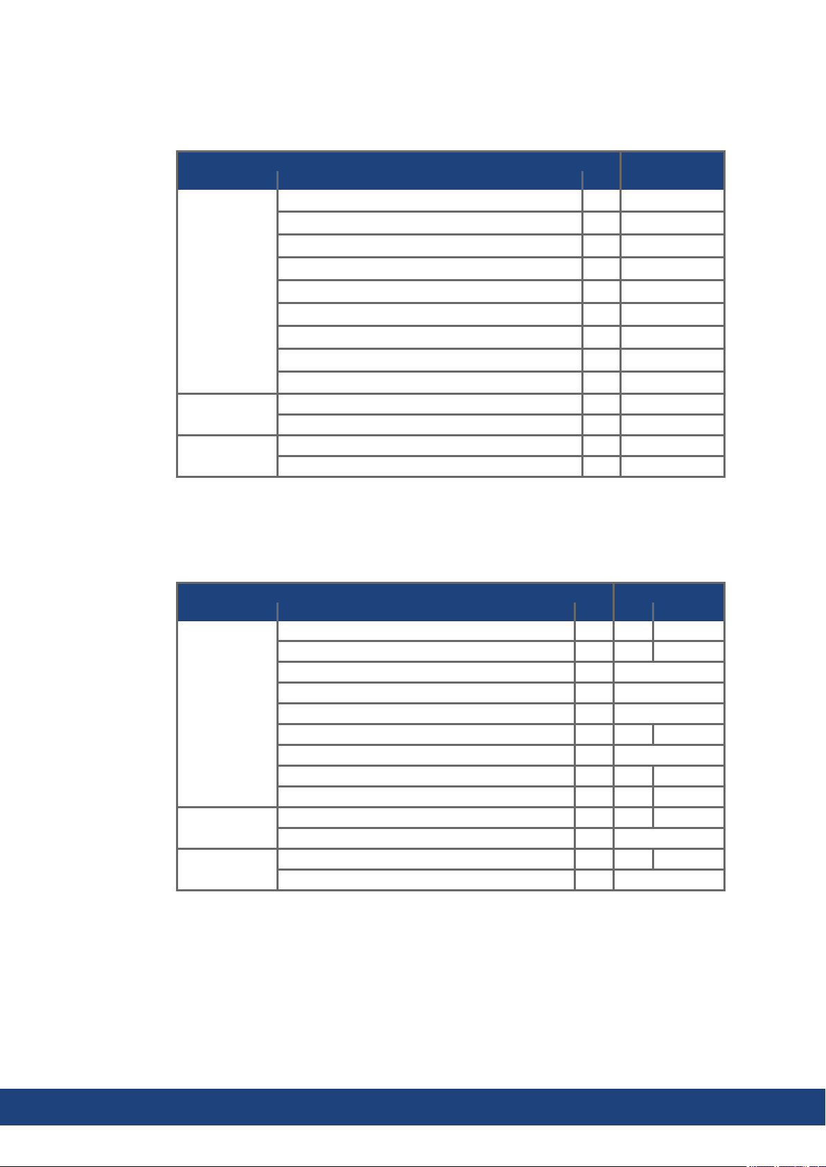
6.6.2.2 Technical data for AKD2G-Sxx-6V
Technical data for the regenerative circuit depends on the drive type and the mains voltage.
Supply voltages, capacitance, and switch-on voltages are all nominal values.
Brake circuit AC Supply
AKD2G-Sxx- Rated data Units 120V / 240V
6Vxxy
all types
Regenstart voltage at rated supply voltage V 380
Overvoltage limit V 420
Maximum regenerative duty cycle % 35*
Internal regen resistor Ω 15
Continuous power, internal resistor W 100
Peak brake power, internal resistor (0.5s) kW 3 / 9
External regenresistor (recommended 15 Ω) Ω >10
Continuous brake power, external resistor kW 3
Peak brake power, external (1s) kW 5 / 14
6V03S, 6V06S Absorption energy in capacitors (±20%) Ws 6 / 23
DC Bus Capacitance µF 1640
6V12S, 6V03D,
6V06D
Absorption energy in capacitors (± 20%) Ws 9 / 35
DC Bus Capacitance µF 2460
* depends on connected regen resistor power.
6.6.2.3 Technical data for AKD2G-Sxx-7V
Technical data for the regenerative circuit depends on the drive type and the mains voltage.
Supply voltages, capacitance, and switch-on voltages are all nominal values.
Brake circuit AC Supply
AKD2G-Sxx- Rated data Units 240V 400V/480V
7V03S ,7V06S,
7V12S, 7V03D,
7V06D
Regenstart voltage at rated supply voltage V 380 633 / 760
Overvoltage limit V 420 840
Maximum regenerative duty cycle % 35*
Internal regen resistor Ω 33
Continuous power, internal resistor W 100
Peak brake power, internal resistor (0.5s) kW 4 17
External regenresistor (recommended 33 Ω) Ω >25
Continuous brake power, external resistor kW 2 6
Peak brake power, external (1s) kW 6 24
7V03S, 7V06S Absorption energy in capacitors (±20%) Ws 3 30 / 18
DC Bus Capacitance µF 235
7V12S, 7V03D,
7V06D
Absorption energy in capacitors (±20%) Ws 6 50 / 35
DC Bus Capacitance µF 470
* depends on connected regen resistor power.
38 Kollmorgen | kdn.kollmorgen.com | July 2020
Page 39
AKD2G-S Installation Manual, Safety 1 | 6 Technical description anddata
6.7 LCD Display and Push-buttons (B1, B2)
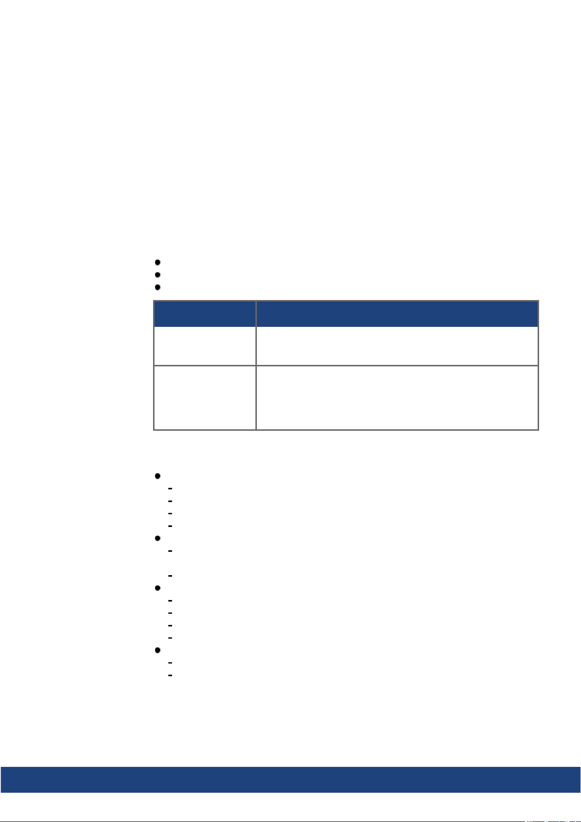
The drive offers an LCD display and two push-buttons B1 / B2 for navigation.
Push-button actions
A short button press invokes the action corresponding to the symbol directly above the button. On the dashboard for example,
a short press on B1 causes the menu system to appear, and
a short press on B2 causes a help screen to appear.
A long press (greaterthan 2 seconds) on B2 returns the display to the previous screen.
More B1 / B2 Functions
Boot from SD card Push both buttons during power up to boot with data from SD card.
Boot from flash fallback image
LCD display
Left Coloredsection
Color: axis status (enabled, disabled, or faulted).
First icon: axis command source (analog, service, electronic gearing, or fieldbus).
Secondicon: axis operationmode (torque, velocity, or position).
Axis ID: A1 or A2.
Right Non-colored section:
No Fault/Warning: three virtual LEDs corresponding to axis disable sources
(Safe Torque Off, Hardware Enable, and Controlled Stop).
Faults or warnings: fault or warningcode.
Center blue bar:
Drive and axis names
IP address
Drive model number
Firmware version
Bottom blue bar:
indicates whetherthe service port is connected to WorkBench, and
shows the actions that will be invoked by pushing the B1 / B2 buttons.
Description
Press the buttons first, then hold it down while turning on the 24 V
powersupply.
Remove the SD card, then press both buttons and hold them down
while turning on the 24 V power supply to boot from an on-board
recovery image. The fallback image includes a set of bootloader,
operational, andcontrol FPGA that implements sufficient programmingsupport to update missing or corrupt files.
Kollmorgen | kdn.kollmorgen.com | July 2020 39
Page 40

AKD2G-S Installation Manual, Safety 1 | 6 Technical description anddata
Dual axes LCD display
For dual-axis drives, the top section shows axis 1 information, the bottom section those for
axis 2.
Single axis LCD display
For single axis drives, the top section shows axis 1 information while the section betweenthe
center and bottom bars is a data area where some important actual values of the axis are visible: position, velocity, current.
40 Kollmorgen | kdn.kollmorgen.com | July 2020
Page 41
AKD2G-S Installation Manual, Safety 1 | 6 Technical description anddata
Faults and Warnings
The display shows the code of the fault or warning that occurred. If a fault occurs, the color of
the left section switches to red. Navigate with B1 / B2 to the Fault screen to see a short
description of the fault or warning.
See WorkBench Onlinehelp for more details.
6.8 SD Card Slot
Supported SD card types
SD cards are formatted by the manufacturer. The following table outlines the SD card types
andAKD2G support.
SD Type File System Capacity Supported
SD (SDSC) FAT16 1MB to 2GB YES
SDHC FAT32 4GB to 32GB YES
SDXC exFAT (Microsoft) >32GB to 2TB NO
AKD2G offer a SD card slot
to boot the drive with data from the SD Memory
card
These features can be started from the drive display
using push-buttons B1/B2.
Features
Boot AKD2G with data from SD card:
Remove 24V. Apply 24V with buttons B1 and B2 pressed. Release buttons after the display is updated.
Kollmorgen | kdn.kollmorgen.com | July 2020 41
Page 42

AKD2G-S Installation Manual, Safety 1 | 7 Mechanical Installation
7 Mechanical Installation
7.1 Important Notes 43
7.2 Guide to Mechanical Installation 43
7.3 Dimensions 44
42 Kollmorgen | kdn.kollmorgen.com | July 2020
Page 43
AKD2G-S Installation Manual, Safety 1 | 7 Mechanical Installation
7.1 Important Notes
High EMC Voltage Level!
Risk of electrical shock, if the servo amplifier(or the motor) is not properly EMC-grounded.
Do not use painted (i.e. non-conductive) mountingplates.
In unfavourable circumstances, use copper mesh tape between the earthing bolts and
earth potential to deflect currents.
Protect the drive from impermissible stresses. In particular, do not let any components
become bent or any insulation distances altered during transport and handling. Avoid contact with electronic components and contacts.
The drive will switch itself off in case of overheating. Ensure that there is an adequate flow
of cool, filtered air into the bottom of the control cabinet, or use a heat exchanger(➜ # 31).
Do not mount devices that produce magnetic fields directly besidethe drive. Strongmagnetic fields can directly affect internal components. Install devices which produce magnetic
field with distance to the drives and/or shield the magnetic fields.
7.2 Guide to Mechanical Installation
The following tools are required(at a minimum)to install the AKD2G; your specific installation may require additional tools:
M5 hexagon socket-cap screws (ISO 4762)
4 mm hexagon ball headscrewdriver
No. 2 Phillips head screwdriver
Small slotted screwdriver
Install the drive unit as follows:
1. Prepare the site.
Mount the drive in a closed control cabinet (ambient conditions (➜ # 31)). The site must
be free from conductive or corrosive materials. For the mounting position in the cabinet
(➜ # 44).
2. Check ventilation.
Check that the ventilation of the drive is unimpeded, and keepwithin the permitted ambient temperature (➜ # 31). Keep the required space clearance above and below the drive
(➜ # 44).
3. Check the cooling system.
If cooling systems are used for the control cabinet, position the cooling system so that
condensationwater cannot drip onto the drive or peripheral devices.
4. Mount the drive.
Assemble the drive and power supply near each otheron the conductive, grounded
mounting plate in the cabinet.
5. Ground the drive.
For EMC-compliant shieldingand grounding, (➜ # 52). Ground the mounting plate, motor
housing andCNC-GND of the control system.
Kollmorgen | kdn.kollmorgen.com | July 2020 43
Page 44
AKD2G-S Installation Manual, Safety 1 | 7 Mechanical Installation
7.3 Dimensions
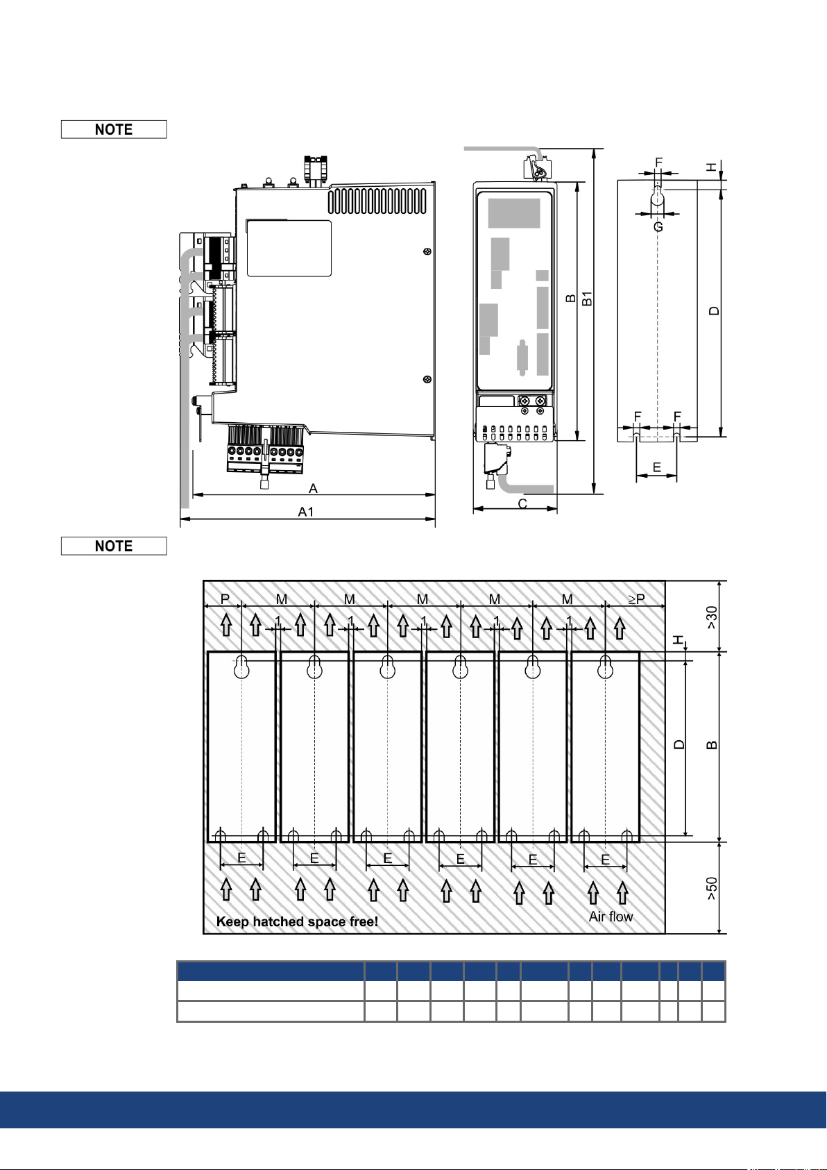
Mounting: 3 x M5 hexagon socket screws to ISO 4762, 4 mm hexagon ball head screwdriver
Outlinewidth and height dimensions are measuredon footprint level (mounting plate).
Dimensions on the front plate areslightly smaller. All dimensions in mm.
Dimensions in mm A A1 B B1 C D E F G H M P
AKD2G-Sxx-6V (3 to 12 A) 221 232 235 303 76 221,5 36 5,8 11,5 7 78 40
AKD2G-Sxx-7V (3 to 12 A) 221 232 272 340 75 259 36 5,8 11,5 6 78 40
44 Kollmorgen | kdn.kollmorgen.com | July 2020
Page 45

AKD2G-S Installation Manual, Safety 1 | 8 Electrical Installation
8 Electrical Installation
8.1 Important Notes 46
8.2 Guide to electrical installation 47
8.3 Wiring 48
8.4 EMI Noise Reduction 52
8.5 Connection Overview 57
8.6 Power and Logic Voltage Supply (X3/X10) 67
8.7 DC Bus link (X3) 76
8.8 Regen resistor (X3) 78
8.9 Motor Power, Brake and Feedback connection 79
8.10 EEO, Electronic Gearing, Master-Slave 92
8.11 EtherNet Fieldbus Interface (X11/X12) 95
8.12 CAN-Bus Interface (X13/X14) 98
8.13 Service Interface (X20) 101
8.14 Modbus TCP (X20) 102
8.15 I/O Connection (X21/X22/X23) 103
Kollmorgen | kdn.kollmorgen.com | July 2020 45
Page 46
AKD2G-S Installation Manual, Safety 1 | 8 Electrical Installation
8.1 Important Notes
Only professional staff who arequalified in electrical engineering are allowed to install the
drive. Wires with color green with one or more yellow stripes must not be used other than for
protective earth (PE) wiring.
High Voltage up to 900 V!
There is a dangerof serious personal injury or death by electrical shock or electrical arcing.
Capacitors can still have dangerous voltages present up to 5 minutes after switchingoff the
supply power. Control and power connections can still be live, even if the motor is not rotating.
Only install andwire the equipment whenit is not live.
Make sure that the cabinet is safely disconnected (for instance, with a lock-out and warning signs).
Never remove electrical connections to the drive while it is live.
Wait at least 5 minutes after disconnecting the drive from the main supply power before
touching potentially live sections of the equipment (e.g. contacts) or undoing any connections.
To be sure, measure the voltage in the DC bus link andwait until it has fallen below 50 V.
Wrongmains voltage, unsuitable motor orwrong wiring will damage the drive. Check the
combination of drive and motor. Compare the rated voltage and current of the units. Implement the wiring according to the matching connection diagram, see (➜ # 59) and following.
Make sure that the maximum permissible rated voltage at the terminals L1, L2, L3 or +DC, –
DC is not exceeded by more than10% even in the most unfavorable circumstances (see
IEC 60204-1).
Excessively high external fusing will endanger cables anddevices. The fusing of the mains
powerand logic power must be installedby the user. Hints for use of Residual-current circuit
breakers (RCD) (➜ # 18).
Since the leakage current to PE is more than 3.5 mA, in compliance with IEC61800-5-1the
PE connection must eitherbe doubled or a connecting cable with a cross-section >10 mm²
must be used. Deviating measures according to regional standards might be possible.
The drive status shall be monitored by the PLC to acknowledge critical situations. We
recommend wiring the ready to operate relay contact in series into the emergency off circuit
of the installation. The emergency off circuit must operate the supply contactor.
It is permissible to use the setup software to alter the settings of the drive. Any other alterations will invalidate the warranty.
46 Kollmorgen | kdn.kollmorgen.com | July 2020
Page 47

8.2 Guide to electrical installation
Kollmorgen recommends to install the drive electrical system as follows:
1. Select cables in accordance with IEC 60204 (➜ # 49).
2. Install shielding and groundthe drive.
For EMC-compliant shieldingand grounding, see (➜ # 52).
Ground the mounting plate, motor housing and CNC-GND of the control system.
3. For functional safety information, see (➜ # 133).
4. Wire the drive and connectors.
Observe the "Recommendations for EMI noise reduction": (➜ # 52).
Wire the "Ready to Operate" contact into the emergency off circuit of the system.
Connect the digital control inputs and outputs.
Connect up analog ground (also if a fieldbus is used).
Connect the analog input source, if required.
Connect the motor (hybrid cable or power, brake and feedback cables).
Connect shielding at both ends.
If required, connect the external regen resistor (with fusing).
AKD2G-Sxx-6V: connect EMC filters (shielded lines between filter and drive) for
second environment requirements to product category C2.
Connect the auxiliary voltage supply
Connect the main electrical supply.
Check maximum permitted voltage value (➜ # 33).
Check proper use of residual-current circuit breakers (RCD): (➜ # 18).
Connect the PC (➜ # 101) for setting up the drive.
AKD2G-S Installation Manual, Safety 1 | 8 Electrical Installation
5. Check the wiring against the wiringdiagrams:
Overview AKD2G single axis (➜ # 59)
Overview AKD2G dual-axis (➜ # 60)
Connector pinout (➜ # 61) ff
Mains power supply: (➜ # 68) ff
Logic power supply: (➜ # 75)
DC Bus Link: (➜ # 76)
External Regen Resistor: (➜ # 78)
Motor singlecable connection: (➜ # 80)
Motor dual cable connection: (➜ # 82)
Motor Holding Brake: (➜ # 84)
Feedback Connection (➜ # 86)
Encoder emulation: (➜ # 92)
Electronic gearing: (➜ # 94)
Master Slave: (➜ # 94)
EtherNet Fieldbus interface: (➜ # 95)
CAN bus interface: (➜ # 98)
Service interface: (➜ # 101)
Digital and analog I/O: (➜ # 103)
Functional Safety option 1: (➜ # 137)
Kollmorgen | kdn.kollmorgen.com | July 2020 47
Page 48
AKD2G-S Installation Manual, Safety 1 | 8 Electrical Installation
8.3 Wiring
Only professional staff who arequalified in electrical engineering are allowed to install the
drive. Wires with color green with one or more yellow stripes must not be used other than for
protective earth (PE) wiring. Wheninstalling orreplacingcables, use only standardized components, which complies to the cable andwire requirements (➜ # 49).
8.3.1 General
High Voltage up to 900 V!
There is a dangerof serious personal injury or death by electrical shock or electrical arcing.
Only install andwire the equipment whenit is not live, that is, when neither the electrical
supply nor the 24 V auxiliary voltage nor the supply voltages of any otherconnected
equipment is switchedon.
Make sure that the cabinet is safely disconnected (for instance, with a lock-out and warning signs). The individual voltages are switched on for the first time duringsetup.
The chassis ground symbol, which is used in all the wiringdiagrams, indicates that you
must take care to provide an electrically conductive connection with the largest feasible surface areabetween the unit indicated andthe mounting plate in the control cabinet. This connection is for the effective grounding of HF interference, andmust not be confused with the
PE-symbol (PE = protective earth, safety measureas per IEC 60204).
8.3.2 Mating connectors
Connectors X1, X2, X10T, X21, X22 are springclamp connectors.
X3 connector with screw terminals, tighteningtorque 0.5 to 0.6 Nm (4.4 to 5.3 inlbs).
X3T-type connectors on request.
Connectors X22 and X23 areoptional.
# Description Type
X1/2
X3/X3T
X10T 24V power supply T-type connector , 2 pol. 2.5 mm², 14 awg
X11/12 EtherNet Fieldbus RJ45 0,5 mm², 21 awg
X13/14 CAN In/Out RJ25 0,5 mm², 21 awg
X20 Service Port RJ45 0,5 mm², 21 awg
X21 I/O control signals Connector, 2x11 pol. 1.5 mm², 16 awg
X22 I/O control signals Connector, 2x10 pol. 1.5 mm², 16 awg
X23 Conventional feedback models SubD 15pol. HD (female) 0,5 mm², 21 awg
Motor, two wire feedback, holding brake
Mains power, regenresistor,
DC-Bus
Max. Cross
Section
Connector, 4 pol. power 10 mm², 8 awg
Connector, 4 pol. signal 0.5 mm², 21 awg
Connector or T-type, 8 pol. 6 mm², 10 awg
48 Kollmorgen | kdn.kollmorgen.com | July 2020
Page 49
8.3.3 Cable and Wire Requirements
8.3.3.1 Cable material
For informationon the chemical, mechanical, andelectrical characteristics of the cables
please refer to the Kollmorgen 2G Cable Guide or contact customersupport.
To reach the maximum permitted cable length, you must use cable material with the following capacitance requirements:
Motor power cable: less than 150pF/m (phase core to shieldcapacitance)
Motor Feedback cable: less than 120 pF/m (signal core to shieldcapacitance)
Hybrid motor cable:
- less than 120 pF/m (phase core/core capacitance)
- less than 210 pF/m (phase core/shieldcapacitance)
- less than 120 pF/m (signal core/core capacitance)
- less than 210 pF/m (signal core/shield capacitance)
- BUS Element: 45 pF/m @ 800kHz & charact. wave resistance 110±10Ω @ 10MHz
8.3.3.2 Cable Length
Cables should not exceed the maximum lengths stated below. The recommended maximum cable length of motor cables depends on the used cable material and the feedback
type. Cable functionality is only guaranteed up to the maximum length when using unmodified Kollmorgen engineered cables.
AKD2G-S Installation Manual, Safety 1 | 8 Electrical Installation
Motor cables (X1, X2, X4, X5, X23, X41)
Length of motor power cables, feedback cables andmotor brake cables is equal.
Performance Line Cables Performance Line Cables Value Line Cables
Feedback Max. Length [m] Feedback Max. Length [m] Feedback Max. Length [m]
SFD3 50
DSL 25
Endat 2.2 25
Resolver 50
I/O cables (X21, X22)
Maximum distance for unshieldedI/O lines is 3 m inside the cabinet. If the I/O cable leaves
the cabinet, it must be EMC shielded.
8.3.3.3 T-Connector wiring
If you use mating T-connectors for 24 VDC supply, mains voltage supply andDC-Bus link,
you must prepare the connecting cables with wire end ferrules.
You can prepare cables with cross-section 2.5 mm² (up to to 6 mm²) with a uniform length of
170mm, if the modules are linedup close together.
Use wire end ferrules with plastic collars, for example 2.5 mm² x 17 mm.
AKM2G AKM
All 25 All 12
Kollmorgen | kdn.kollmorgen.com | July 2020 49
Page 50
AKD2G-S Installation Manual, Safety 1 | 8 Electrical Installation
8.3.3.4 Cable cross sections and requirements
The tables below describe the recommended interface cross sections and cable requirements relatedto AKD2G in accordance with IEC 60204. For multi-axes systems, observe
the specific operating conditions for your system.
Power Cables
Mains supply
1x3 A:
2x3 A:
1x6 A:
2x6 A:
1x12 A:
Cross Section
EU US
1.5 mm²
1.5 mm²
1.5 mm²
2.5 mm²
2.5 mm²
14 awg
14 awg
14 awg
14 awg
14 awg
Remarks
600V rated ,minimum 75°C
24 V supply max. 2.5 mm² 14 awg single core
DC bus link,
Regenresistor
3/6 A:
12 A:
1.5 mm²
2.5 mm²
14 awg
14 awg
1000 V rated, min. 75°C,
shielded for lengths >0.20 m
I/O cables
Analog I/Os min. 0.25mm² 24 awg shielded twisted pairs
Digital I/Os 0.5 mm² 20 awg singlecore
Motor Power Cable (power) & Motor Combination Cable (power & brake)
Cross Section [mm]
Cable Combi Cable
(4x1) (4x1.0+(2x0.75)) 0A < I0rms ≤ 10.1A
(4x1.5) (4x1.5+(2x0.75)) 10.1A < I0rms ≤ 13.1A
(4x2.5) (4x2.5+(2x1.0)) 13.1A < I0rms ≤ 17.4A
(4x4) (4x4.0+(2x1.0)) 17.4A < I0rms ≤ 23A
(4x6) (4x6.0+(2x1.0)) 23A < I0rms ≤ 30A
Current Carrying
Capacity
Remarks
1000 V Rated, 80°C
Current carrying capacity
acc. to IEC 60204-1:2006
Table 6, Column B2
The brackets (...) show
the shielding.
Motor Feedback Cable
Type Cross Section [mm] Remarks
Resolver (4x2x0.25)
EnDat 2.1, BiSS B (6x2x0.25)
HIPERFACE (5x2x0.25)
EnDat 2.2, BiSS C (5x2x0.25)
SFD (3x2x0.25)
300V rated, 80°C
Shielded twisted pairs
The brackets (...) show
the shielding.
Comcoder (8x2x0.25)
Motor Hybrid Cable
Type Cross Section [mm]
Current Carrying
Capacity
SFD3/DSL (4x1.0+(2x0.34)+(2x0.75)) 0A < I0rms ≤ 10.1A
SFD3/DSL (4x1.5+(2x0.34)+(2x0.75)) 10.1A < I0rms ≤ 13.1A
SFD3/DSL (4x2.5+(2x0.34)+(2x1.0)) 13.1A < I0rms ≤ 17.4A
SFD3/DSL (4x4.0+(2x0.34)+(2x1.0)) 17.4A < I0rms ≤ 23A
SFD3/DSL (4x6.0+(2x0.34)+(2x1.0)) 23A < I0rms ≤ 30A
Endat 2.2
Endat 2.2
(4x1.5+(2x0.75)+
(2x2x0.14+2x0.25))
(4x4.0+(2x1.0)+
(2x2x0.14+2x0.25))
10.1A < I0rms ≤ 13.1A
17.4A < I0rms ≤ 23A
Remarks
1000 V rated, 80°C
Current carrying capacity
acc. to IEC 60204-1:2006
Table 6, Column B2
4 power lines &
2 brake lines &
2 SFD3/DSL signal lines
or
6 EnDat 2.2 signal lines
50 Kollmorgen | kdn.kollmorgen.com | July 2020
Page 51
8.3.4 Protective Earth connection
Protective Earth connection of the system components is a safety measure per IEC 60204.
Ensurethe proper groundingof all components with the PE rail in the control cabinet as reference potential. Connect each ground individually with the intended groundingcable (neutral
point connection).
The leakage current from AKD2G against PE is more than 3.5 mA. In accordance with EN
61800-5-1, the PE connection must therefore either be double implemented or a connection
cable with >10mm² cross-section used.
In order to keep the impedance as low as possible, we recommenda copper earthing strap
for the PE connection on the PE block.
Wire the PE connections immediately after installing the devices as the first electrical connection. Now you insert all the otherlines and connectors. For disassembly, release the PE
connections as the last connection.
AKD2G-S Installation Manual, Safety 1 | 8 Electrical Installation
For the use of residual current protective devices (RCD), refer to (➜ # 18).
Kollmorgen | kdn.kollmorgen.com | July 2020 51
Page 52
AKD2G-S Installation Manual, Safety 1 | 8 Electrical Installation
8.4 EMI Noise Reduction
Electromagnetic Fields!
Electromagnetic radiation may, by acting on electrically conductive materials, leadto potential hazardous danger(warming, failure of implants).
Work on the electrical installation may only be performed by trained andqualified personnel, in compliance with the regulations for safety at work, and only with switched off
mains supply, and securedagainst restart.
Grounding, equipotential bonding and radiation-reducing shields may not be removed.
8.4.1 Recommendations for EMI noise reduction
The following guidelines will help you to reduce problems with electrical noise in your application.
Ensure good connections between the cabinet components. Connect the back
panel andcabinet door to the cabinet body using several conductive braids. Never rely on
hinges or mounting bolts for ground connections.
Ensure good ground connection. Connect from cabinet to proper earth ground. Ground
leads should be the same gauge as the leads to main power, but must cover the regional
legal requirements, example (➜ # 51).
Use Kollmorgen cables. Route power and control cables separately, Kollmorgen recommends a distance of at least 200mm to improve interference immunity.
Ground the shielding at both ends. Groundall shielding with largeareas (low impedance), with metalized connector housings or shield connection clamps whereverpossible. For cables entering a cabinet, connect shields on all 360° of the cable. Never
connect a simple “pigtail.” For more information on shielding concepts, (➜ # 53).
With separate mains filter, maintain separation of leads entering and exiting the
mains filter (line power filter). Locate the filter as close as possible to the point where
the incomingpower enters the cabinet. If it is necessary for input power and motorleads
to cross, cross them at 90°.
Observe cable length limits. Maximum distance for unshielded I/O lines is 3 m inside
the cabinet. If the I/O cable leaves the cabinet, it must be EMC shielded.
Feedback lines and Hybrid Cables may not be extended, since the shielding
would be interrupted and the signal processing may be disturbed.Install all feed-
back cables with an adequate cross-section, per IEC 60204 (➜ # 49) and use the requested cable material to reach maximum cable length.
Splice cables properly. If you need to divide cables, use connectors with metal backshells. Ensurethat both shells connect along the full 360° of the shields.
Use differential inputs for analog signals. Noise susceptibility in analog signals is
greatly reduced by using differential inputs. Use twisted-pair, shieldedsignal lines, connecting shields on both ends.
Cables between drives and filters or external regen resistors must be shielded.
Install all power cables with an adequate cross-section per IEC 60204 (➜ # 49) and use
the requested cablematerial to reach maximum cable length.
52 Kollmorgen | kdn.kollmorgen.com | July 2020
Page 53

AKD2G-S Installation Manual, Safety 1 | 8 Electrical Installation
8.4.2 Shielding with external shielding busbar
For best practice use of shielded cables Kollmorgen recommends a star point shield connection, for example, with a shielding busbar.
8.4.2.1 Shielding Concept
Example with AKD2G-Sxx--6Vxx, EMC filter and external regen resistor.
Kollmorgen | kdn.kollmorgen.com | July 2020 53
Page 54
AKD2G-S Installation Manual, Safety 1 | 8 Electrical Installation
8.4.2.2 Shielding Busbar
The power cable shields (line in, motor cable, external regen resistor) can
be routed to an additional busbar via shieldclamps.
Kollmorgen recommends using Weidmüller KLBÜ shield clamps.
A possible scenario for setting up a busbar for the above shieldclamps is
described below.
1. Cut a busbar of the required
length from a brass rail (cross-section 10 x 3 mm) and drill holes in it
as indicated. All shield clamps
required must fit between the drill
holes.
Risk of injury due to the spring
force of the coil spring.
Use pincers.
2. Squeeze togetherthe coil spring
andthe supportingplate and push
the busbar through the opening in
the holder.
3. Mount the busbarwith the
shield clamps fitted on the
assembly plate. Use either metal
spacer bushes or screws with
nuts and accessories to maintain
a spacing of 50 mm. Earth the busbarusing a single conductor with a
cross-section of at least 2.5 mm².
4. Strip the external cable sheath
to a length of approx. 30 mm, taking care not to damage the braided
shield. Push the shield clamp up
androute the cable to it via the busbar.
Make sure there is goodcontact
between the shield clamp and the
braided shield.
54 Kollmorgen | kdn.kollmorgen.com | July 2020
Page 55

8.4.3 Shielding connection to the drive
You can connect cable shielding directly to the drive by using grounding plates, shield connection clamps, and a motor connector with strain relief and grounding plate.
8.4.3.1 Shielding Concept
Example with AKD2G-Sxx--7Vxx, dual-axis.
AKD2G-S Installation Manual, Safety 1 | 8 Electrical Installation
Kollmorgen | kdn.kollmorgen.com | July 2020 55
Page 56

AKD2G-S Installation Manual, Safety 1 | 8 Electrical Installation
8.4.3.2 Grounding plates and shield connection clamps
A grounding plate is mounted to the drive.
Use shield connection clamps (see accessories manual). These hook into the
grounding plate and ensure optimum contact betweenthe shield and the grounding plate.
Kollmorgen recommends using Phoenix Contact SK14 shield clamps with cable
clamp range of 6-13mm.
8.4.3.3 Motor connector X1/X2 with shielding connection
Alternative connection for the motor powerconnection by mating connector with shieldplate
andstrain relief. Kollmorgen motor powerand hybrid motor cables are configured with shield
plate.
Strip the external cable sheath to a length of
approx. 80 mm, taking care not to damage the
braided shield. Push the braided shield (1)back
over the cable and secure with a rubber sleeve (2)
or shrink sleeve.
Shorten all the wires apart from the protective earth
(PE) wire (green/yellow) by about 20 mm so that
the PE wire is now the longest wire. Strip all wires
andfit wire end ferrules.
Securethe braided shield of the cable with metal
cable ties (3) and fasten the cable.
Wire the connector as shown in the connection diagram. Plug in the connector to the socket on the
front of the AKD2G and secure it with the red clip.
56 Kollmorgen | kdn.kollmorgen.com | July 2020
Page 57

8.5 Connection Overview
8.5.1 Connector Position AKD2G-Sxx-6V
The graphics shows an AKD2G with supply voltage110 V to 240 V.
X2 is available with dual-axis drives only.
Optional: I/O, F3 or DX (➜ # 27).
AKD2G-S Installation Manual, Safety 1 | 8 Electrical Installation
Kollmorgen | kdn.kollmorgen.com | July 2020 57
Page 58

AKD2G-S Installation Manual, Safety 1 | 8 Electrical Installation
8.5.2 Connector Position AKD2G-Sxx-7V
The graphics shows an AKD2G with supply voltage240 V to 480 V.
X2 is available with dual-axis drives only.
Optional: I/O, F3 or DX (➜ # 27).
58 Kollmorgen | kdn.kollmorgen.com | July 2020
Page 59

8.5.3 Wiring overview, single axis drive
AKD2G-S Installation Manual, Safety 1 | 8 Electrical Installation
Kollmorgen | kdn.kollmorgen.com | July 2020 59
Page 60

AKD2G-S Installation Manual, Safety 1 | 8 Electrical Installation
8.5.4 Wiring overview, dual axis drive
60 Kollmorgen | kdn.kollmorgen.com | July 2020
Page 61
8.5.5 Connector pin assignments
Information to connectors and wiring (➜ # 48).
8.5.5.1 X1 and X2: Motor, Brake, Feedback 1
Pin Label Signal Description
1 U U Motor phase U
2 V V Motor phase V
3 W W Motor phase W
retention latch, shield screw
5 PE PE Protective earth
B+ B+ BR+ Motorholdingbrake +
B- B- BR- Motor holding brake -
F+ F+ COM+ SFD3 + or HIPERFACE DSL +
F- F- COM- SFD3 - or HIPERFACE DSL -
AKD2G-S Installation Manual, Safety 1 | 8 Electrical Installation
4 pin, pitch 7.62 mm plus 2x2 pin pitch 3.81 mm
Spring clamps
Locking screw, tightening torque 0.5 Nm (4.4 inlbs)
Motor power, Motor brake (X1: axis 1, X2: axis 2)
X1: Input for commutation feedback 1 (➜ # 86)
X2: Input for commutation feedback 2 (➜ # 86)
Wiring example:
DC Bus link (➜ # 76)
Motor singlecable connection (➜ # 80)
Motor dual cable connection (➜ # 82)
8.5.5.2 X3: Mains, regen resistor, DC-Bus
Pin Label Signal Description
1 PE PE Protective earth
2 R L1 3~ mains supply L1, 1~ supply L, DC supply +
3 S L2 3~ mains supply L2
4 T L3 3~ mains supply L3, 1~ supply N, DC supply 5 Ri RBint internal regen resistor
6 RE -RB external regen resistor 7 +DC +DC (+RBext) DC Bus link+ and/or external regen resistor +
8 -DC -DC DC Bus link -
8 pin, pitch 7.62 mm
Screw terminals, tighteningtorque 0.5 to 0.6 Nm (4.4 to 5.3 inlbs)
Locking screw, tightening torque 0.5 Nm (4.4 inlbs)
Optional T version
Mains supply, External regen resistor, DC Bus
X3/5 to X3/6 must be shorted to use the built in regen resistor.
Remove the jumper to connect an external regen resistor .
Wiring example:
Power supply (➜ # 67)
DC Bus link (➜ # 76)
External regenresistor (➜ # 78)
Kollmorgen | kdn.kollmorgen.com | July 2020 61
Page 62
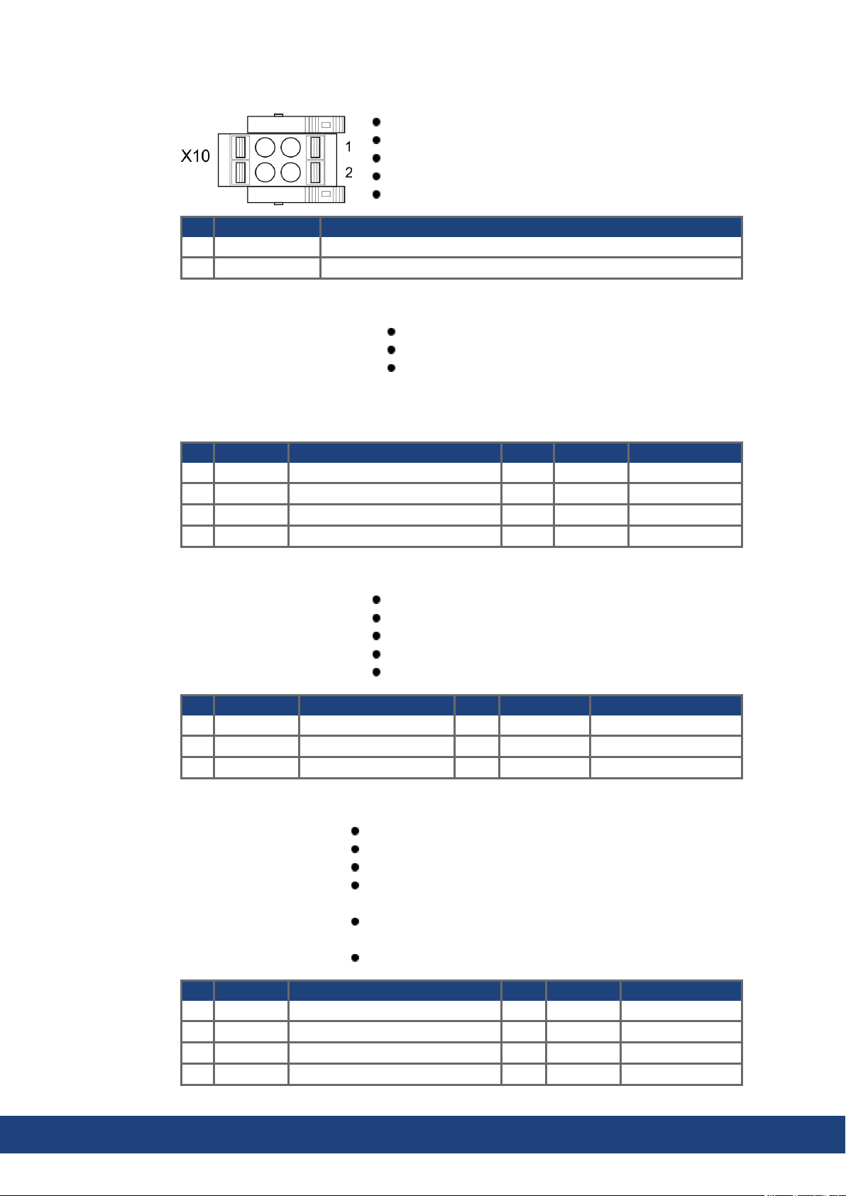
AKD2G-S Installation Manual, Safety 1 | 8 Electrical Installation
8.5.5.3 X10: 24 VDC
2 pin, pitch 5.08 mm
Spring clamps
T version
24 VDC supply voltage
Wiring example: (➜ # 75)
Pin Signal Description
1 + 24 V +24 VDC supply voltage, PELV
2 GND Ground for 24 VDC supply voltage, PELV
8.5.5.4 X11, X12: EtherNet Fieldbus
RJ45 with built-in green/red dual-color LED
EtherCAT, EtherNet/IP*, PROFINET*
Interface Details: (➜ # 95)
*available 2021
Pin Signal Description Pin Signal Description
1 Tx+ Transmit + 5 Term. Termination
2 Tx- Transmit - 6 Rx- Receive 3 Rx+ Receive + 7 Term. Termination
4 Term. Termination 8 Term. Ttermination
8.5.5.5 X13, X14: CAN bus (optional)
Pin Signal Description Pin Signal Description
1 n.c. not used 4 CAN_low CAN bus low signal
2 Shield Chassis 5 CAN_GND CAN bus ground
3 CAN_high CAN bus high signal 6 n.c. not used
8.5.5.6 X20: Service
RJ-25
X14 IN port, X13 OUT port
Up to 1 Mbit operation
Node ID to be set by WorkBench
Interface Details: (➜ # 98)
RJ45 with built-in green and yellow LEDs
100/10 Mbit EtherNet TCP/IP, Modbus/TCP
Supports auto-IP, DHCP and fixed IP addressing
Supports point-to-point (i.e. Auto-IP) and connection by using
network switches
Supports automatic discovery in WorkBench if in the same
sub-net.
Interface Details: (➜ # 101)
Pin Signal Description Pin Signal Description
1 Tx+ Transmit + 5 Term. Termination
2 Tx- Transmit - 6 Rx- Receive 3 Rx+ Receive + 7 Term. Termination
4 Term. Termination 8 Term. Termination
62 Kollmorgen | kdn.kollmorgen.com | July 2020
Page 63
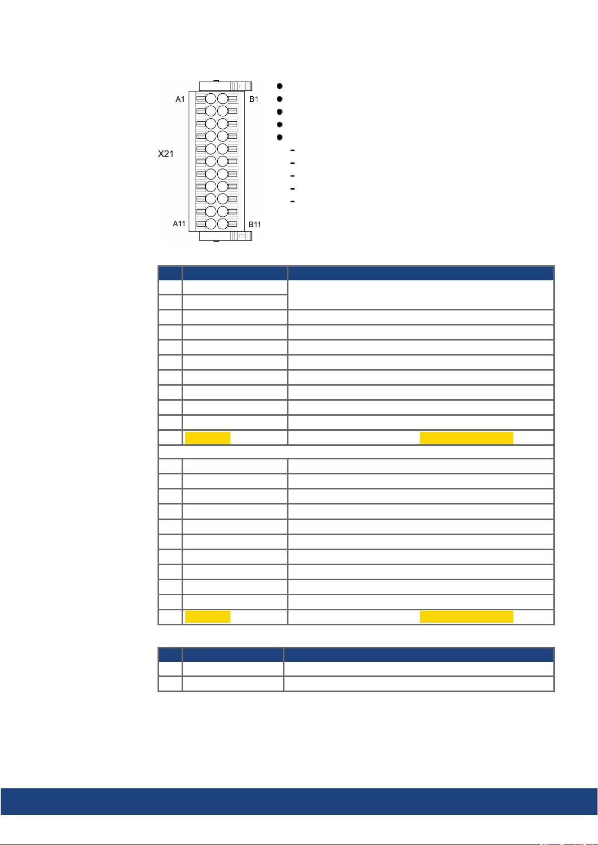
8.5.5.7 X21: I/O, Feedback 4
Digital I/O connectivity
Pin Signal Description
A1 Analog-In (AIN) 1 +
A2 Analog-In (AIN) 1 A3* Digital-In (DIN) 1 Fast, isolated, sink, type EN 61131-2type 1
A4* Digital-In (DIN) 2 Fast, isolated, sink, type EN 61131-2type 1
A5 Digital-In (DIN) 3 Slow, isolated, sink, type EN 61131-2 type 1
A6 Digital-In (DIN) 4 Slow, isolated, sink, type EN 61131-2 type 1
A7 Digital-In (DIN) 5 Slow, isolated, sink, type EN 61131-2 type 1
A8 Digital-In (DIN) 6 Slow, isolated, sink, type EN 61131-2 type 1
A9 Digital-In (DIN) 7 Slow, isolated, sink, type EN 61131-2 type 1
A10 Digital-In (DIN) 8 Slow, isolated, sink, type EN 61131-2 type 1
A11 STO-A-A1 Slow, isolated, sink, fail-safe, STO axis 1 channel A
AKD2G-S Installation Manual, Safety 1 | 8 Electrical Installation
2 x 11 pins (left column A, right column B), pitch 3.5 mm
Spring clamps
Analog and digital I/O
Input for feedback 4 (➜ # 86)
Wiring examples:
Analog input (➜ # 105)
Analog output (➜ # 106)
Digital input (➜ # 107)
Digital Output (➜ # 111)
Feedback (➜ # 88)
Analog Input +/- 10 V
B1 Analog-Out (AOUT) 1 Analog Output, 0 to +10 V
B2 AGND Ground for analogI/O
B3 +24 V +24 VDC for digital I/O andSTO
B4 DGND Ground for digital I/O andSTO
B5 Digital-Out (DOUT) 9 + Relay contact, normally open, 24 VDC, 1A
B6 Digital-Out (DOUT) 9 - Relay contact, normally open, 24 VDC, 1A
B7 Digital-Out (DOUT) 1 Isolated, high-side, 100 mA
B8 Digital-Out (DOUT) 2 Isolated, high-side, 100 mA
B9 Digital-Out (DOUT) 3 Isolated, high-side, 100 mA
B10 Digital-Out (DOUT) 4 Isolated, high-side, 100 mA
B11 STO-B-A1 Slow, isolated, sink, fail-safe, STO axis 1 channel B
*Feedback 4 connectivity, Step/Direction CW/CCW (input)
Pin Signal Description
A3 Step, CW Fast, isolated, sink, type EN 61131-2 type 1
A4 Direction, CCW Fast, isolated, sink, type EN 61131-2 type 1
Kollmorgen | kdn.kollmorgen.com | July 2020 63
Page 64
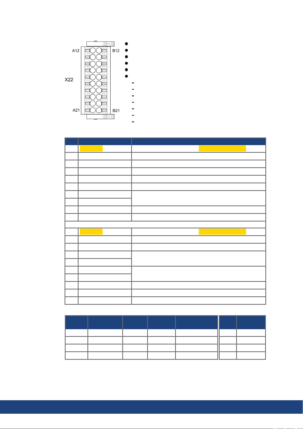
AKD2G-S Installation Manual, Safety 1 | 8 Electrical Installation
8.5.5.8 X22: I/O, EEO2, Feedback 5
2 x 10 pins (left column A, right column B), pitch 3.5 mm
Spring clamps
Analog and digital I/O
Input for feedback 5 (➜ # 86)
Output for incremental encoder emulation (EEO2)
Wiring examples:
Analog input (➜ # 105)
Analog output (➜ # 106)
Digital input (➜ # 107)
Digital output (➜ # 111)
Feedback (➜ # 89)
Encoder emulation (EEO2) (➜ # 92)
Master-Slave (➜ # 94)
Digital I/O connectivity
Pin Signal Description
A12 STO-A-A2 Slow, isolated, sink, fail-safe, STO axis 2 channel A
A13 Digital-In (DIN) 9 Slow, isolated, sink, type EN 61131-2 type 1
A14 Digital-In (DIN) 10 Slow, isolated, sink, type EN 61131-2type 1
A15 Digital-In (DIN) 11 Slow, isolated, sink, type EN 61131-2type 1
A16 Digital-In (DIN) 12 Slow, isolated, sink, type EN 61131-2type 1
A17 AGND Groundfor analog I/O
A18 Analog-In (AIN) 2+
A19 Analog-In (AIN) 2-
Analog Input, +/- 10 V
A20* Digital-In/Out (DIO) 1 + RS485 input or output
A21* Digital-In/Out (DIO) 1 - RS485 input or output
B12 STO-B-A2 Slow, isolated, sink, fail-safe, STO axis 2 channel B
B13 Digital-Out (DOUT) 5 Isolated, high-side, 100 mA
B14 Digital-Out (DOUT) 6 Isolated, high-side, 100 mA
B15 Digital-Out (DOUT) 7 +
B16 Digital-Out (DOUT) 7 B17 Digital-Out (DOUT) 8 +
B18 Digital-Out (DOUT) 8 -
Fast, isolated, sink or source, 100 mA
Fast, isolated, sink or source, 100 mA
B19 Analog-Out (AOUT) 2 AnalogOutput, 0 to +10 V
B20* Digital-In/Out (DIO) 2 + RS485 input or output
B21* Digital-In/Out (DIO) 2 - RS485 input or output
*Feedback 5 (input)
Pin Increm.
Encoder
Step/
Dir
CW/
CCW
EnDAT 2.2
A20 Track A + Step + CW + CLK+
A21 Track A - Step - CW - CLKB20 Track B + Dir + CCW + DAT+
B21 Track B - Dir - CCW - DAT-
BiSS B/C
*EEO2 (output)
Pin Increm.
A20 A+
A21 A B20 B+
B21 B -
Encoder
64 Kollmorgen | kdn.kollmorgen.com | July 2020
Page 65
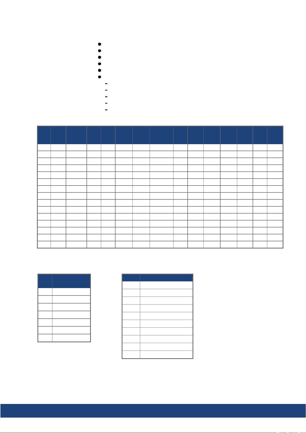
8.5.5.9 X23: I/O, EEO1, Feedback 3
Sub-D highdensity 15 pin, female
Locking screws, tightening torque 0.4 Nm (3.5 inlbs)
Input for feedback 3 (➜ # 86)
Output for incremental encoder emulation (EEO1)
Additional Digital-In/Out
Wiring examples:
Feedback (➜ # 90)
Encoder emulation (EEO1) (➜ # 93)
Master-Slave (➜ # 94)
Digital input (➜ # 107)
Digital output (➜ # 111)
Feedback 3 connectivity (input)
AKD2G-S Installation Manual, Safety 1 | 8 Electrical Installation
X23
SFD
Pin
1 - - - - - - - - HallU - HallU HallU - 2 - - CLK+ CLK+ CLK+ CLK+ - - HallV - HallV HallV - 3 - - CLK- CLK- CLK- CLK- - - HallW - HallW HallW - 4 SEN+ - SEN+ SEN+ SEN+ SEN+ SEN+ SEN+ SEN+ SEN+ SEN+ - - 5 SEN- - SEN- SEN- SEN- SEN- SEN- SEN- SEN+ SEN+ SEN+ - - 6 COM+ R1 Ref+ DAT+ DAT+ DAT+ DAT+ DAT+ Zero+ Zero+ Zero+ Zero+ - - 7 COM- R2 Ref- DAT- DAT- DAT- DAT- DAT- Zero- Zero- Zero- Zero- - - 8 - Th+ Th+ - Th+ - Th+ Th+ Th+ Th+ Th+ Th+ Th+ Th+
9 - Th- Th- - Th- - Th- Th- Th- Th- Th- Th- Th- Th10 +5 V - +5 V +5 V +5 V +5 V +5 V +5 V +5 V +5 V +5 V +5 V +5 V +5 V
11 0 V - 0 V 0 V 0 V 0 V 0 V 0 V 0 V 0 V 0 V 0 V 0 V 0 V
12 - S1SIN+ A+ - A+ - SIN+ A+ A+ A+ A+ - Step+ CW+
13 - S3SIN- A- - A- - SIN- A- A- A- A- - Step- CW14 - S2COS+ B+ - B+ - COS+ B+ B+ B+ B+ - Dir+ CCW+
15 - S4COS- B- - B- - COS- B- B- B- B- - Dir- CCW-
CLK = CLOCK, DAT = DATA, SEN = SENSE, Th = Thermal control
EEO1 connectivity (output)
Pin
6 Zero+
7 Zero11 0 V
12 A +
13 A14 B+
15 B-
Resol-
ver
Incremental
Encoder
BiSSBBiSSCEnDAT
2.1
Digital I/O connectivity
Pin Digital I/0
EnDAT
2.2
HIPER
FACE
2 Digital-In/Out 6 +
3 Digital-In/Out 6 6 Digital-In/Out 5 +
7 Digital-In/Out 5 10 +5 V
11 0 V
12 Digital-In/Out 3 +
13 Digital-In/Out 3 -
Sine/
Cos
Sine/
Cos
+Hall
Incr.
Enc.
Incr.
Enc.
+Hall
Hall
Step/
Dir
14 Digital-In/Out 4 +
15 Digital-In/Out 4 -
CW/
CCW
Kollmorgen | kdn.kollmorgen.com | July 2020 65
Page 66
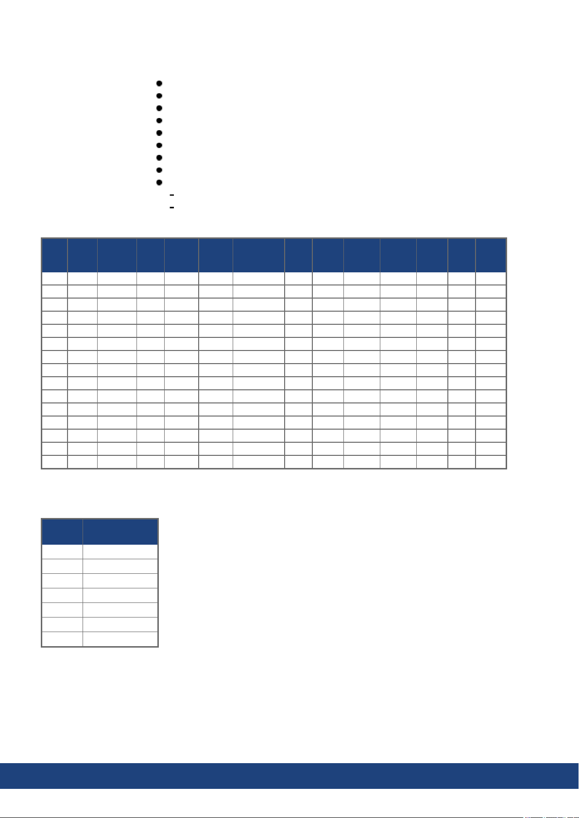
AKD2G-S Installation Manual, Safety 1 | 8 Electrical Installation
8.5.5.10 X41: SFA Feedback converter, EEO3/EEO4 (accessory)
Sub-D highdensity 15 pin, female
Locking screws, tightening torque 0.4 Nm (3.5 inlbs)
1 m cable, 3 flying leads with ferrules for connection to X1, X2
Input for electronic gearing
When connected to X1: Input for feedback 1 (➜ # 86)
When connected to X2: Input for feedback 2 (➜ # 86)
Output for incremental encoder emulation (EEO3 / EEO4) (➜ # 93)
SFA Adapter converts conventional feedback signals to 2 wire feedback format
Wiring examples:
Feedback and Encoder emulation (➜ # 91)
Master-Slave (➜ # 94)
Feedback 1/2 connectivity (input)
Cos
Sine/
Cos
+Hall
Incr.
Enc.
X41
SFD
Pin
1 - - - - - - - HallU - HallU HallU - 2 - - CLK+ CLK+ CLK+ - - HallV - HallV HallV - 3 - - CLK- CLK- CLK- - - HallW - HallW HallW - 4 SEN+ - SEN+ SEN+ SEN+ SEN+ SEN+ SEN+ SEN+ SEN+ - - 5 SEN- - SEN- SEN- SEN- SEN- SEN- SEN+ SEN+ SEN+ - - 6 COM+ R1 Ref+ DAT+ DAT+ DAT+ DAT+ Zero+ Zero+ Zero+ Zero+ - - 7 COM- R2 Ref- DAT- DAT- DAT- DAT- Zero- Zero- Zero- Zero- - - 8 - Th+ Th+ Th+ - Th+ Th+ Th+ Th+ Th+ Th+ Th+ Th+
9 - Th- Th- Th- - Th- Th- Th- Th- Th- Th- Th- Th10 +5 V - +5 V +5 V +5 V +5 V +5 V +5 V +5 V +5 V +5 V +5 V +5 V
11 0 V - 0 V 0 V 0 V 0 V 0 V 0 V 0 V 0 V 0 V 0 V 0 V
12 - S1SIN+ A+ A+ - SIN+ A+ A+ A+ A+ - Step+ CW+
13 - S3SIN- A- A- - SIN- A- A- A- A- - Step- CW14 - S2COS+ B+ B+ - COS+ B+ B+ B+ B+ - Dir+ CCW+
15 - S4COS- B- B- - COS- B- B- B- B- - Dir- CCW-
CLK = CLOCK, DAT = DATA, SEN = SENSE, Th = Thermal control
Resol-
ver
BiSSBEnDAT
2.1
EnDAT
2.2
HIPER-
FACE
Sine/
Incr.
Enc.
+Hall
Hall
Step/
Dir
EEO3 / EEO4 connectivity (output)
X41 Pin
Incremental
Encoder
6 Zero+
7 Zero11 0 V
12 A +
13 A14 B+
15 B-
CW/
CCW
66 Kollmorgen | kdn.kollmorgen.com | July 2020
Page 67
AKD2G-S Installation Manual, Safety 1 | 8 Electrical Installation
8.6 Power and Logic Voltage Supply (X3/X10)
8.6.1 Mains power supply (X3)
Drives in the AKD2G series can be suppliedas follows:
AKD2G-Sxx-6V
1, 2 or 3 phase industrial AC supply networks: 120V or 240 VAC nominal.
(TN-S or TT networks, see KDN)
DC supply networks: 17 VDC to 370 VDC.
AKD2G-Sxx-7V
3 phase industrial AC supply networks: 240 V, 400V or 480 VAC nominal.
DC supply networks: 34 VDC to 740 VDC.
Connection to other voltage types of AC supply networks is possible with an additional isolating transformer.
Periodic overvoltages between phases (L1, L2, L3) and the PE/housingof the drive must not
exceed 1000 V peak. In accordance with IEC 61800, voltagespikes (< 50 µs) between
phases must not exceed1000 V. Voltage spikes (<50µs) between a phase and the PE/housing must not exceed 2000 V.
8 pin, pitch 7.62 mm
optional T version
Wiring example:
1 phase AC supply (➜ # 68)
2 phase AC supply (➜ # 68)
3 phase AC supply (➜ # 69)
DC supply (➜ # 70)
AKD2G-Sxx-6V requires external EMC filter for use in
industrial environment, product category C.
Mating connector data (➜ # 48)
Fusing with different system structures (➜ # 71) ff
Pin Label Signal 1~ Supply 2~Supply 3~ Supply DC Supply
1 PE PE Protective earth Protective earth Protective earth Protective earth
2 R L1 Phase L1 Phase L1 Phase L1 + DC
3 S L2 n.c. n.c. Phase L2 n.c.
4 T L3 Neutral N Phase L2 Phase L3 - DC
For DC supply: observe notes (➜ # 70).
Kollmorgen | kdn.kollmorgen.com | July 2020 67
Page 68
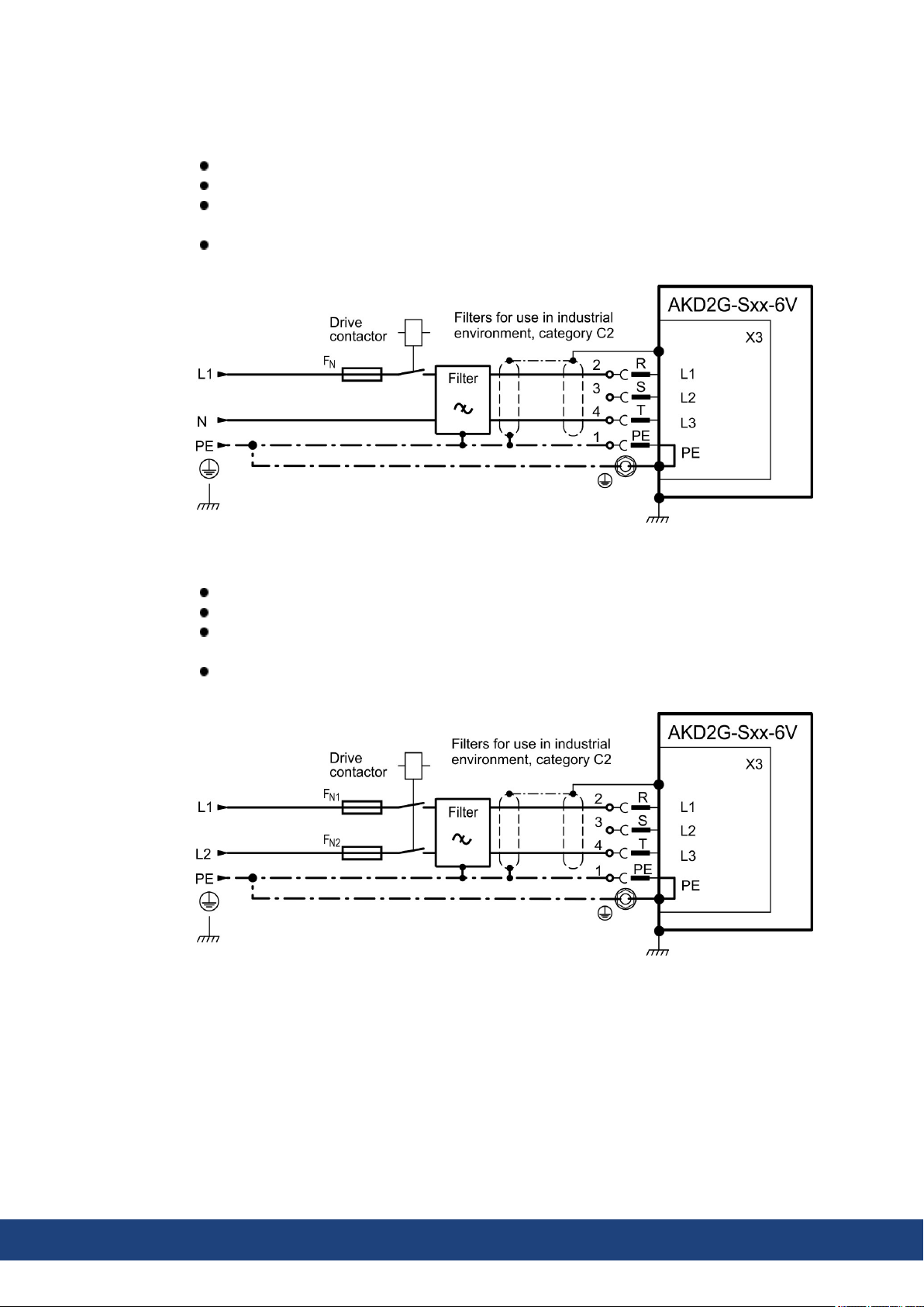
AKD2G-S Installation Manual, Safety 1 | 8 Electrical Installation
8.6.1.1 Wiring examples mains power supply
One phase AC mains (AKD2G-Sxx-6V)
Directly to onephase supply network with neutral line.
Activate single phase supply (VBUS.THREEPHASE = 0).
Set VBUS.ACNOMINAL to desired nominal AC line voltage for lines other thannominal
rated VAC.
AC line filtering to be provided by the user. Use filter type FN2090, refer to the Accessor-
ies Manual for more information. Use shielded cable betweenfilter and drive.
Two phases AC mains (AKD2G-Sxx-6V)
Directly to two-phase supply network without neutral line.
Activate single phase supply (VBUS.THREEPHASE = 0).
Set VBUS.ACNOMINAL to desired nominal AC line voltage for lines other thannominal
rated VAC.
AC line filtering to be provided by the user. Use filter type FN2090, refer to the Accessor-
ies Manual for more information. Use shielded cable betweenfilter and drive.
68 Kollmorgen | kdn.kollmorgen.com | July 2020
Page 69
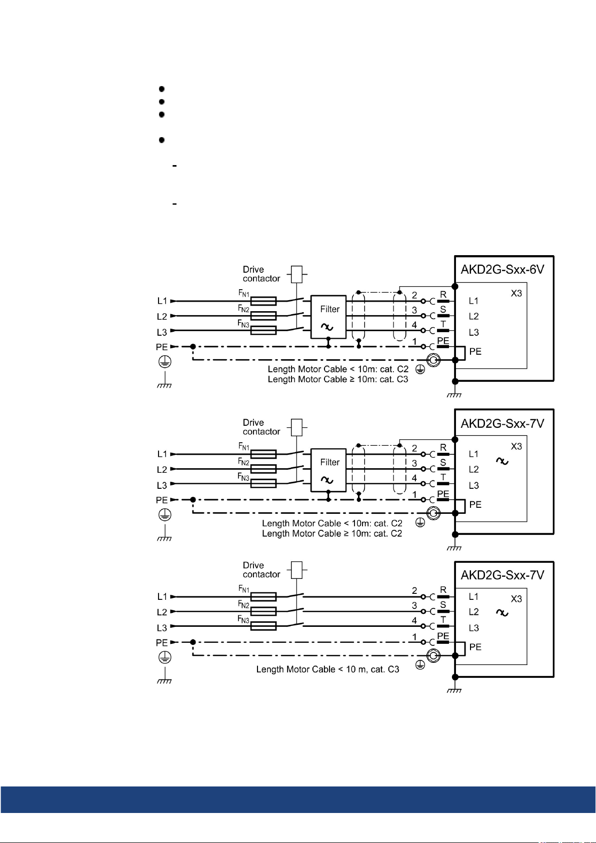
AKD2G-S Installation Manual, Safety 1 | 8 Electrical Installation
Three phases AC mains (all AKD2G-Sxx-)
Directly to 3-phase supply network.
Activate 3-phase supply (VBUS.THREEPHASE = 1).
Set VBUS.ACNOMINAL to desired nominal AC line voltage for lines other thannominal
rated VAC.
AC line filtering to be provided by the user. Refer to the Accessories Manual for more filter
description. Use shielded cablebetween filter and drive.
AKD2G-Sxx-6V:
Motor cable< 10 m: use filter FN 3288in industrial environment, category C2.
Motor cable≥ 10 m: use filter FN 3288 in industrial environment, category C3.
AKD2G-Sxx-7V:
Motor cable< 10 m: no filter, in industrial environment, category C3.
Motor cable< 10 m: use filter FN 3288in industrial environment, category C2.
Motor cable≥ 10 m: use filter FN 3288 in industrial environment, category C2.
Kollmorgen | kdn.kollmorgen.com | July 2020 69
Page 70
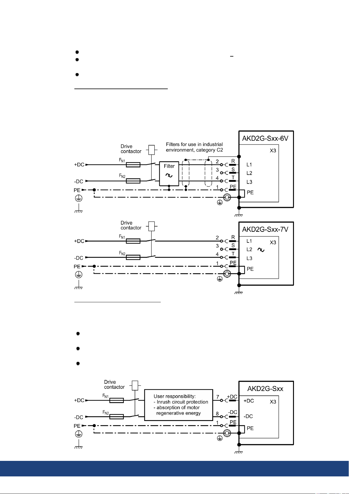
AKD2G-S Installation Manual, Safety 1 | 8 Electrical Installation
DC Supply (all AKD2G-Sxx-)
Activate DC supply (VBUS.DCOPERATION = 1).
Set VBUS.ACNOMINAL to desired DC voltage divide by √2 for VDC other than nominal
rated.
Any DC supply filtering for AKD2G-Sxx-6V to be provided by the user.
DC Supply to mains lines R/T (L1/L3)
DC power source is connected to the drive AC line inputs. This wiring provides soft start of
the energy storagecapacitors inside the drive and the AC rectifier diodes prevents motor
regeneration energy from returning to the dc power source. That is, by powering the drive
from the AC line input connections, the drive’s energy absorption and energy dissipation
mechanisms can work normally.
DC Supply to DC Bus lines X3/7-8
When wiring DC power supply to the drive DC Bus terminals X3 pins 7 and 8, the user is
responsiblefor current and power management using additional external devices.
User resposibility:
The power supply system design must ensure inrush current protection by limiting input
current during power up.
Providea means to safely absorb energy from the motor when slowing down/regenerating. If the DC powersource is a battery energy absorptionshould just work.
DC supply polarity must be properly wired. Improper polarity of DC power will damage
the drive andvoid warranty.
70 Kollmorgen | kdn.kollmorgen.com | July 2020
Page 71
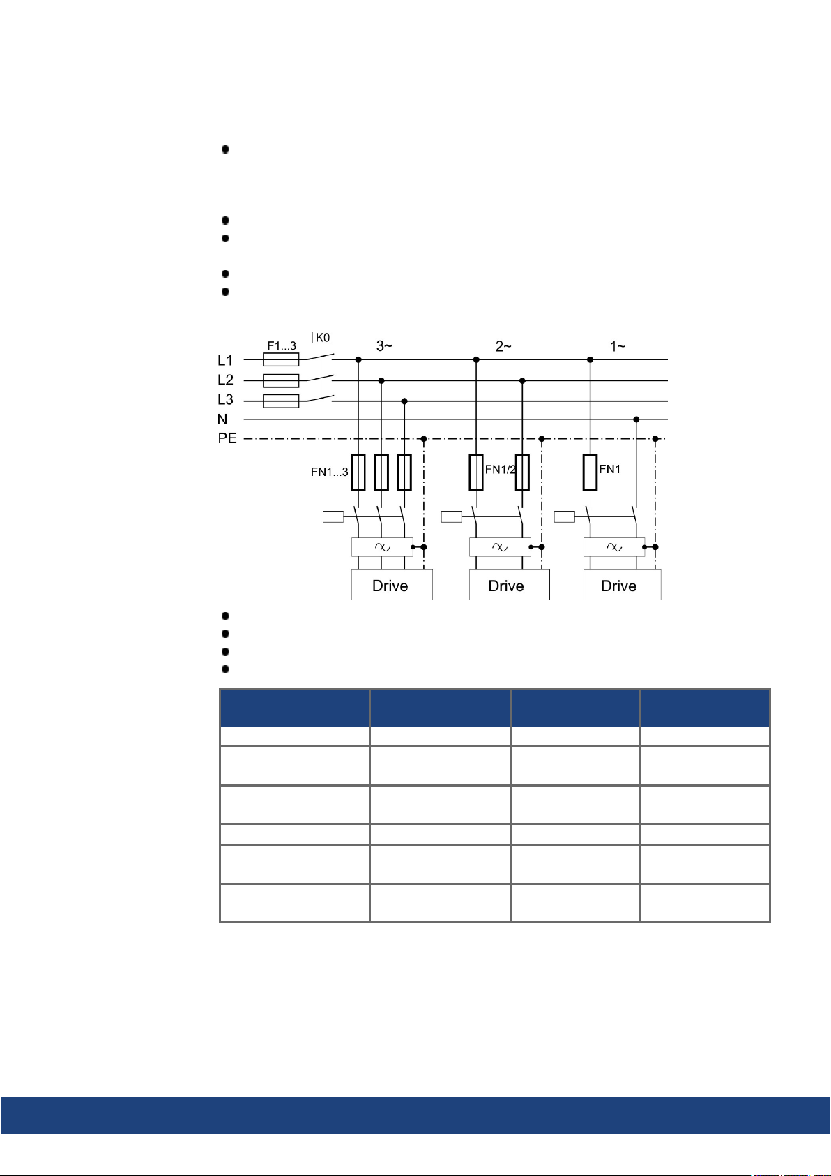
8.6.1.2 Fusing
AKD2G-S Installation Manual, Safety 1 | 8 Electrical Installation
Fuse types
UL fuses: Class J, 600 VAC 200 kA (SCCR rating), time-delay. The fuse must be UL and
CSA listed, UL recognizedis not sufficient. Alternate fuses and breakers to Class J must
have similar or better Ip and I²T performance perUL 508A SB4.2 at the necessary SCCR
rating.
CE fuses: types gS or gG, 400 V/500 V, time-delay
Fuse holders: Combined with the standardfuse blocks, finger safe fuse holders must be
used according to IEC 60529.
Automatic circuit breakers: max. rating is 30 A, observe SCCR rating
Group installationfusing: max. ratingof fuses or breakers for group installation is 30 A
AC supply, single drives, line fusing
F1, F2, F3: depends on sum of current and cabinet requirements.
Filters for special EMC requirements only (➜ # 151).
FN1, FN2, FN3 maximum rating: 30 A.
FN1, FN2, FN3 recommended rating see table below:
Drive
Model
FN1, FN2, FN3:
Ampere rating
Example class J
Eaton
Example class J
Ferraz Shawmut
AKD2G-Sxx-6V03S 10 A (Time-Delay) LPJ10SP/DFJ10 AJT10/HSJ10
AKD2G-Sxx-6V06S
10 A (Time-Delay) LPJ10SP/DFJ10 AJT10/HSJ10
AKD2G-Sxx-6V03D
AKD2G-Sxx-6V12S
15 A (Time-Delay) LPJ15SP/DFJ15 AJT15/HSJ15
AKD2G-Sxx-6V06D
AKD2G-Sxx-7V03S 10 A (Time-Delay) LPJ10SP/DFJ10 AJT10/HSJ10
AKD2G-Sxx-7V06S
10 A (Time-Delay) LPJ10SP/DFJ10 AJT10/HSJ10
AKD2G-Sxx-7V03D
AKD2G-Sxx-7V12S
15 A (Time-Delay) LPJ15SP/DFJ15 AJT15/HSJ15
AKD2G-Sxx-7V06D
Kollmorgen | kdn.kollmorgen.com | July 2020 71
Page 72
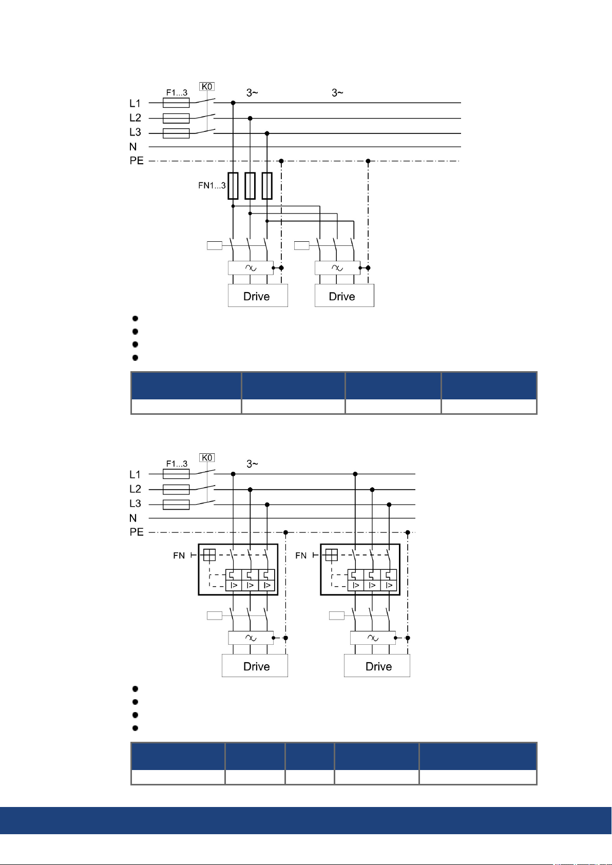
AKD2G-S Installation Manual, Safety 1 | 8 Electrical Installation
AC supply, group of drives, line fusing
F1, F2, F3: depends on sum of current and cabinet requirements.
Filters for special EMC requirements only (➜ # 151).
FN1, FN2, FN3 maximum rating: fuse size for group installation is limited to 30 A max.
FN1, FN2, FN3 rating should be 1.25 * sum current.
Group sum current
FN1, FN2, FN3:
Ampere rating
Example class J
Eaton
Example class J
Ferraz Shawmut
6 A to 30 A 30 A (Time-Delay) LPJ30SP/DFJ30 AJT30/HJ30
AC supply, single drives, automatic circuit breakers
F1, F2, F3: depends on sum of current and cabinet requirements.
Filters for special EMC requirements only (➜ # 151).
FN maximum rating: 30 A
FN recommendedrating and regional approvals see table below:
Drive Model
Ampere
rating
AKD2G-Sxx-6V 15 A 35 kA SU203M-K30 3VA51954EC310
72 Kollmorgen | kdn.kollmorgen.com | July 2020
SCCR
rating
Example UL
Eaton or ABB
Example CE
Siemens
Page 73
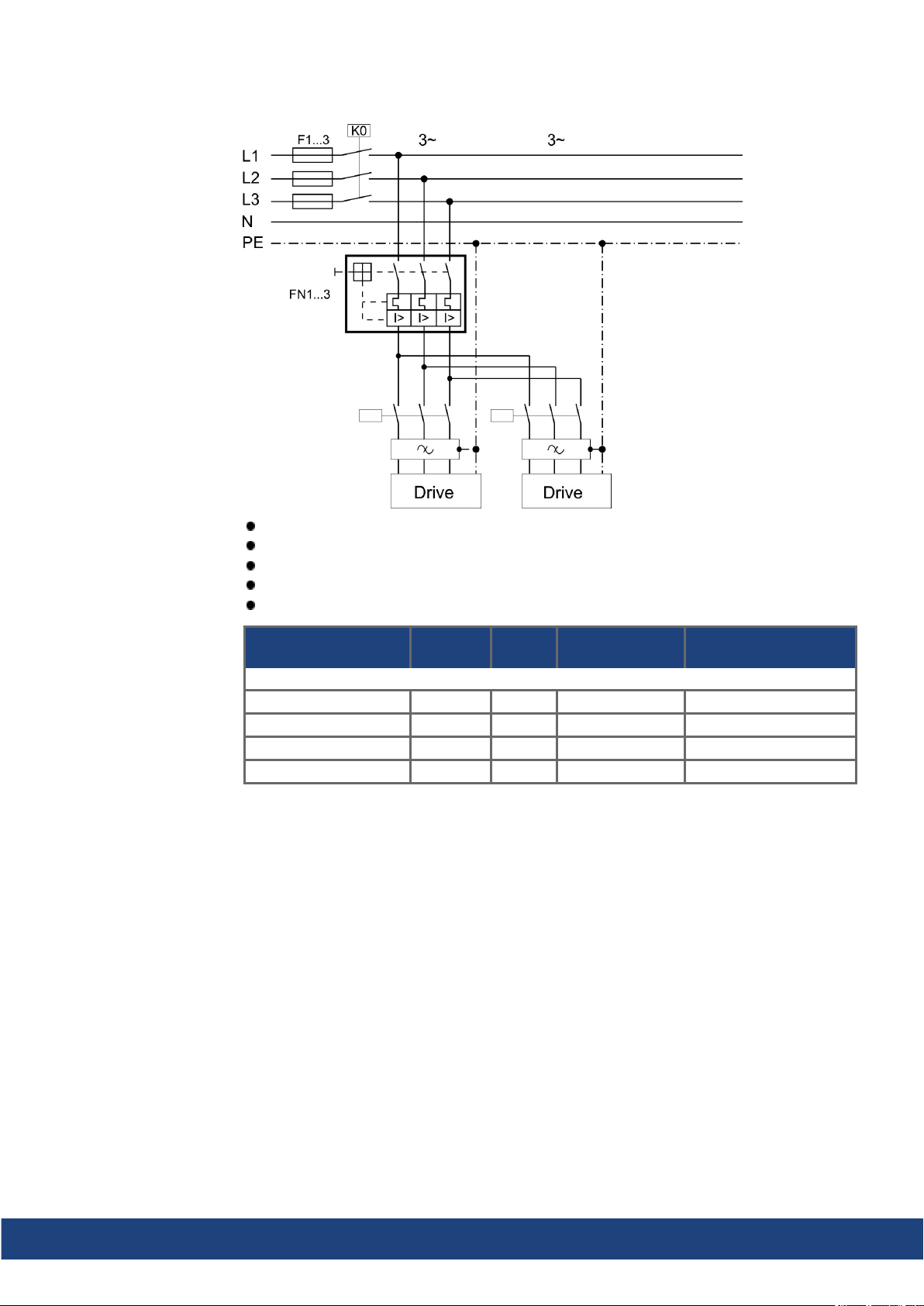
AKD2G-S Installation Manual, Safety 1 | 8 Electrical Installation
AC supply, group of drives, automatic circuit breakers
F1, F2, F3: depends on sum of current and cabinet requirements.
Filters for special EMC requirements only (➜ # 151).
FN maximum rating: circuit breaker size for group installation is limited to 30 A max.
FN rating should be 1.25* sum current.
FN recommendedrating and regional approvals see table below:
Group sum current
Ampere
rating
SCCR
rating
Example UL
Eaton or ABB
Example CE
Siemens
AKD2G-Sxx-6V
6 A to 9A 15 A 10 kA SU203M-K15 3VA51954EC310A
12 A to 15 A 20 A 10 kA SU203M-K20 3VA51204EC310A
18 A to 24 A 30 A 10 kA SU203M-K30 3VA51304EC310A
27 A to 36 A 30 A 10 kA SU203M-K30 3VA51304EC310A
Kollmorgen | kdn.kollmorgen.com | July 2020 73
Page 74
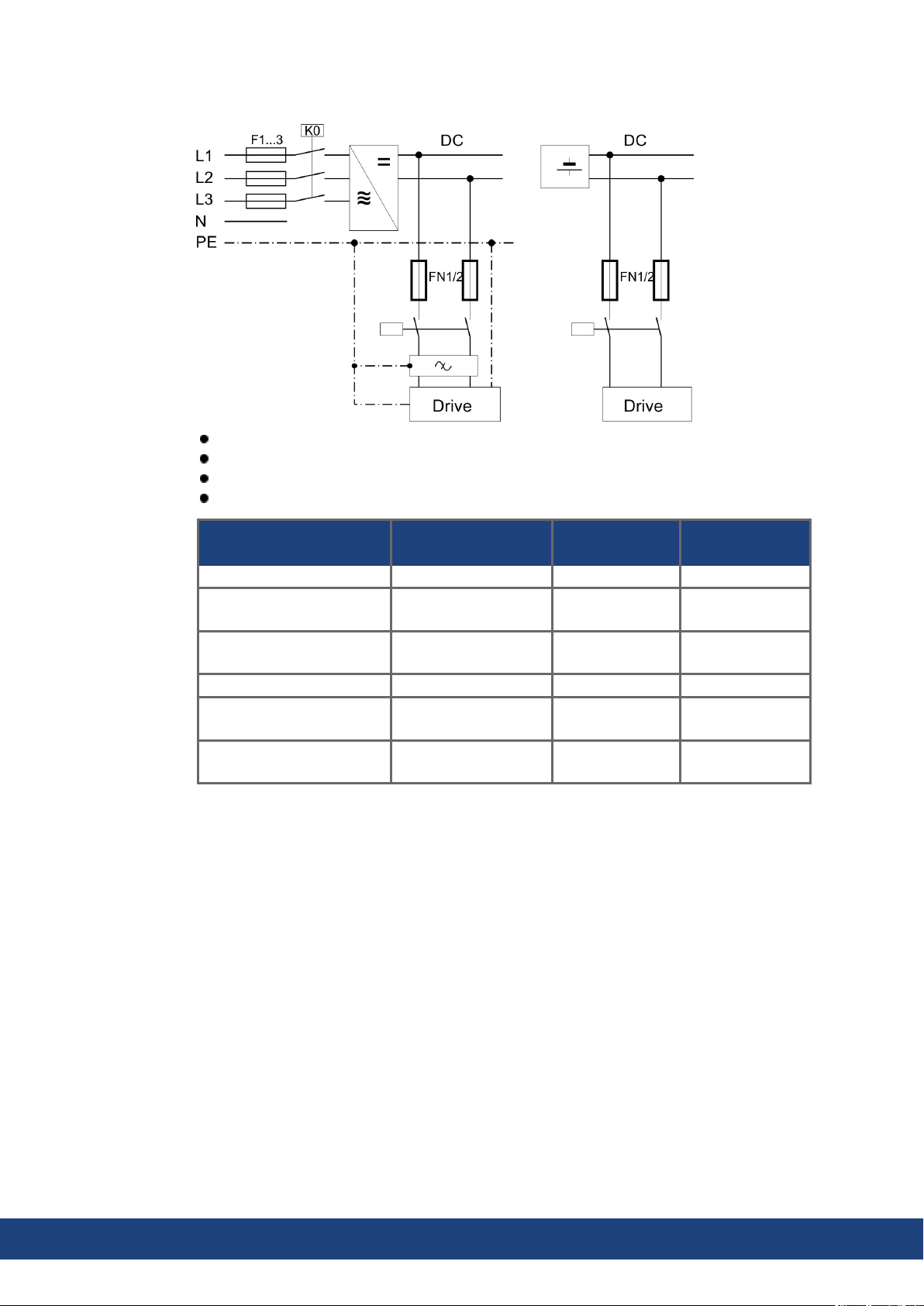
AKD2G-S Installation Manual, Safety 1 | 8 Electrical Installation
DC supply, single drives, line fusing
F1, F2, F3: depends on sum of current and cabinet requirements.
Filters for special EMC requirements only (➜ # 151).
FN1, FN2 maximum rating 30 A
FN1, FN2 recommended rating see table below:
Drive Model Ampere rating
Example UL
Eaton
Example CE
Mersen
AKD2G-Sxx-6V03S 10 A (Time-Delay) DFJ-10 HP6M10
AKD2G-Sxx-6V06S
15 A (Time-Delay) DFJ-15 HP6M15
AKD2G-Sxx-6V03D
AKD2G-Sxx-6V12S
15 A (Time-Delay) DFJ-15 HP6M15
AKD2G-Sxx-6V06D
AKD2G-Sxx-7V03S 10 A (Time-Delay) FWP-10B HP10M10
AKD2G-Sxx-7V06S
10 A (Time-Delay) FWP-10B HP10M10
AKD2G-Sxx-7V03D
AKD2G-Sxx-7V12S
15 A (Time-Delay) FWP-15B HP10M15
AKD2G-Sxx-7V06D
74 Kollmorgen | kdn.kollmorgen.com | July 2020
Page 75
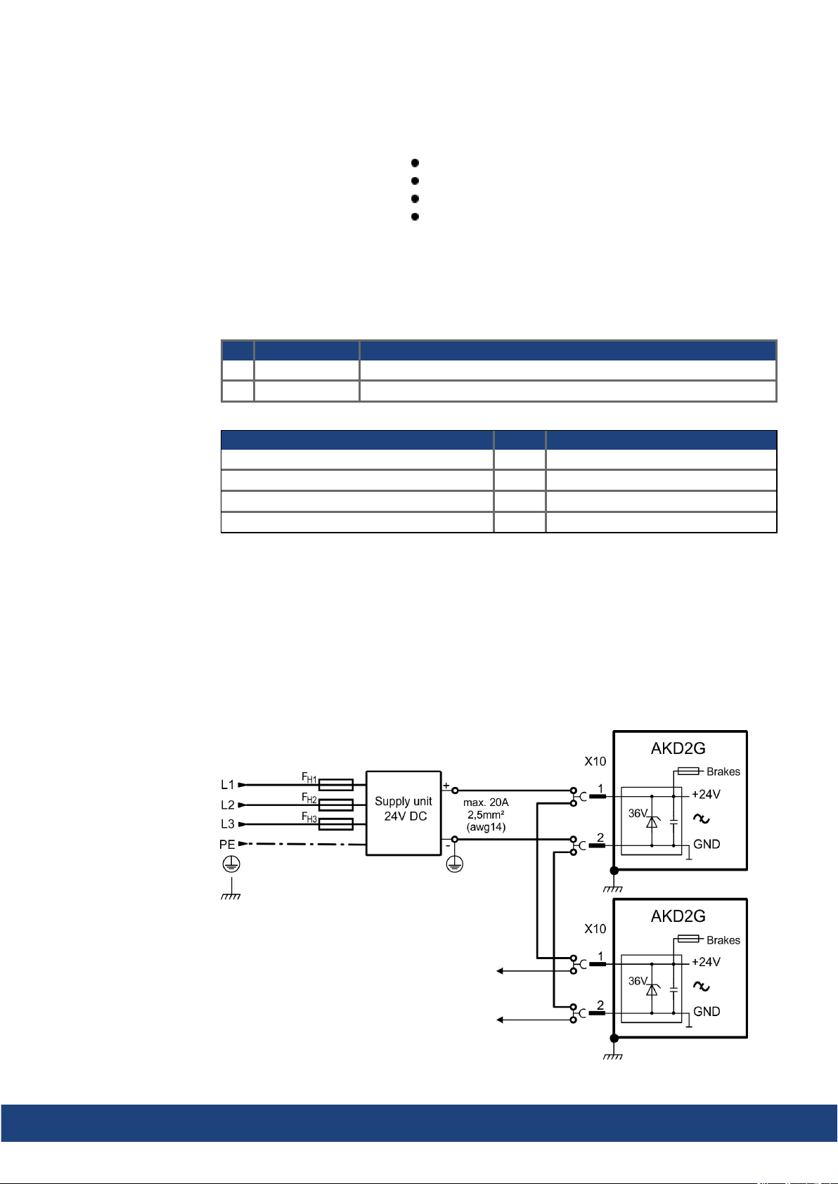
AKD2G-S Installation Manual, Safety 1 | 8 Electrical Installation
8.6.2 Auxiliary voltage power supply 24 VDC (X10)
The following diagram describes external 24 VDC power supply (PELV). The required supply
current rating depends on the use of motor brake (➜ # 33) or (➜ # 35).
2 pin, pitch 5.08 mm
T-type mating connector data (➜ # 48)
Undervoltagefault limit 19 V
Overvoltage fault limit 30 V
Pin Signal Description
1 + 24 V +24 VDC supply voltage, PELV
2 GND Ground for 24 VDC supply voltage, PELV
24 V supply (PELV) Units Input data
Auxiliary voltage supply (PELV) VDC 24 V (±10%, check voltage drop)
- control current without motor brake A < 1
- control current with one motorbrake A < 3.1
- control current with two motor brakes A < 5.2
8.6.2.1 Fusing
Use 24 VDC supply manufacturers recommendation for fusing.
8.6.2.2 Wiring example 24 VDC supply
Maximum current for one string of daisy-chained X10T connectors is 20 A. The sum control
current of connected drives should not extend20 A. With the data given in the table above,
you can connect for example:
6 single axis drives, or 4 dual axis drives, or 3 single + 2 dual axis drives.
Wiring example with three phase powersupply unit:
Kollmorgen | kdn.kollmorgen.com | July 2020 75
Page 76
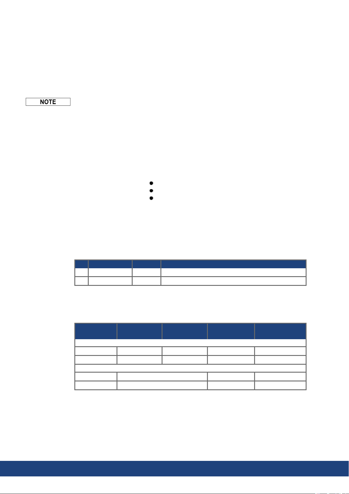
AKD2G-S Installation Manual, Safety 1 | 8 Electrical Installation
8.7 DC Bus link (X3)
The DC bus link can be connected in parallel so that the powerreturned from slowing down
motors is divided between all the drives that are connected to the same DC bus link circuit.
Every drive must have its own power connection to mains voltage sharing the same branch,
over current protection devices, even if the DC bus link is used. Drives working generatively
very often should be placed beside drives, which need energy. That reduces current flow on
longer distances.
The sum of the ratedcurrents for all drives connected in parallel to an AKD2G must not
exceed 48A.
Examples:12S-12S-12D-12D-12D or 06D-12S-12D-06D-06D-03S-03S-03S
Wiring: Use 6mm² unshieldedsingle cores with a max. length of 200mm; use 6mm² shieldedcables for longer lengths. In this case no fuse for line protection is required.
The drives can be destroyed if DC bus link voltages are different. Only drives with mains
supply that share the same AC branch, over current protection devices (identical mains supply voltage) may have the DC bus links interconnected.
Interconnection of DC bus links works best in systems powered by 3-phase AC or DC
power. Consult Kollmorgenfor DC bus linking with single phase AC power input.
8 pin, pitch 7.62 mm
optional T version
Mating connector data (➜ # 48)
8.7.1 Fusing
Pin Label Signal Description
7 +DC +DC DC Bus link positive
8 -DC -DC DC Bus link negative
External regenfusing FB1/FB2 (➜ # 78). DC bus link fusing depends on topology (see next
page (➜ # 77)).
Wiring
topology
AKD2G-Sxx-6V
Group: Fgroup max. 30 A na DFJ-30 HP6M30
Busbar: Fbus max. 15 A na DFJ-15 HP6M15
AKD2G-Sxx-7V
Group: Fgroup max. 30 A FWP-30B HP10M30
Busbar: Fbus max. 15 A FWP-15B HP10M15
Ampere
rating@240V
Ampere
rating@480V
UL region
example Eaton:
CE Region
example Mersen:
76 Kollmorgen | kdn.kollmorgen.com | July 2020
Page 77
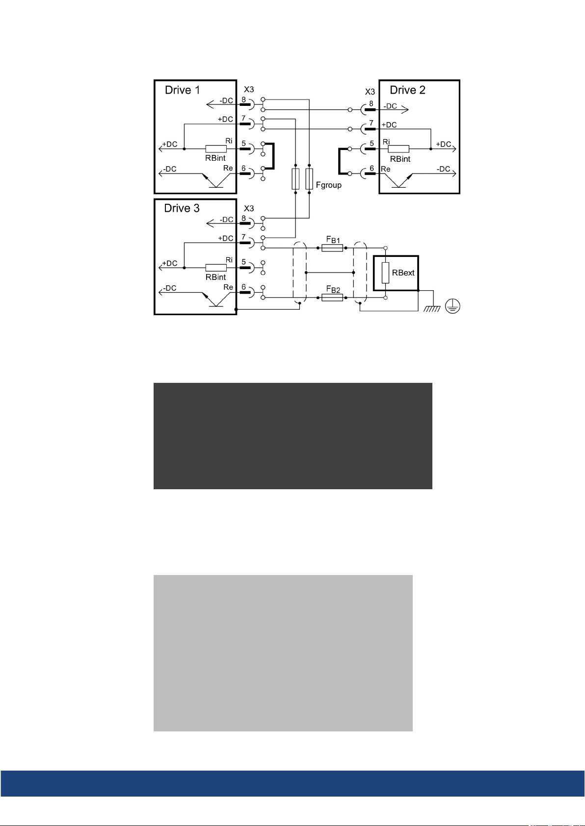
8.7.2 Wiring example with T connectors
AKD2G-S Installation Manual, Safety 1 | 8 Electrical Installation
Without DC Bus fuses, other devices can becomedamaged or destroyed if, for example, a
device fails due to an internal short circuit. If multiple drives areconnected in parallel, then it
is usual to insert DC Bus fuses (Fgroup)between groups of drives (with a groupconsisting of
two or three devices, dependingon the current) in order to limit any possible resulting damage. Fgroup fuses cannot avoid damage by current peaks completely.
8.7.3 Wiring example with busbar
If a device fails in this system due to a short-circuit, only its fuses (Fbus) are tripped and the
rest of the network continues uninterrupted. The solid busbars can conduct significantly largercurrents than T connectors, because the compensating current does not flow through the
connector as above.
Kollmorgen | kdn.kollmorgen.com | July 2020 77
Page 78
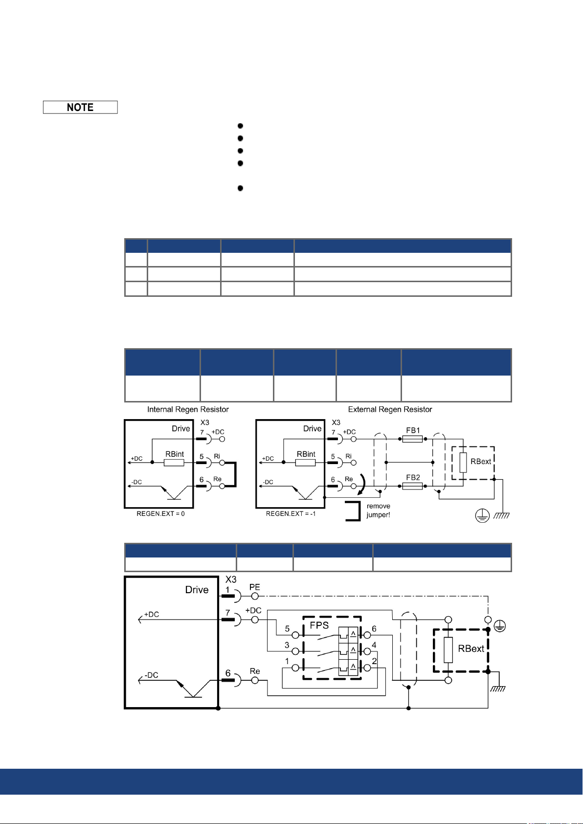
AKD2G-S Installation Manual, Safety 1 | 8 Electrical Installation
8.8 Regen resistor (X3)
For technical data on the regenerative brake circuit (➜ # 37).
Fusing (such as fusible cut-outs or power switches) to be provided by the user.
8 pin, pitch 7.62 mm
optional T version
Mating connector data (➜ # 48).
X3/5 to X3/6 must be shorted to use the built in regen resistor.
Remove the jumper to connect an external regen resistor .
Refer to the WorkBench online helpfor parameter setting
(REGEN.EXT, REGEN.REXT, REGEN.WATTEXT)
Pin Label Signal Description
5 Ri RBint internal Regen resistor
6 Re -RB external Regen resistor 7 +DC +RBext external Regen resistor +
8.8.1 Fusing and Wiring
FB1 / FB2 fusing
Drive Model
all AKD2G-Sxx 10A 40A Eaton
FPS: Frizlen DC Power Switch
RBext FPS Range [In] cable cross section
BAR(U)1500-33 FPS-16 10 to 16 A min. 2.5 mm²
Ampere
rating@240V
Ampere
rating@480V
UL region
example:
FWP-xxA14F
CE Region
example: Siba
110V to 400V: gRL(gS)
400V to 480V: aR
78 Kollmorgen | kdn.kollmorgen.com | July 2020
Page 79
AKD2G-S Installation Manual, Safety 1 | 8 Electrical Installation
8.9 Motor Power, Brake and Feedback connection
The AKD2G drive is able to protect the connected motorfrom overloading, if the parameters
areset correctly andthe thermal protection sensor is connected and supervised. With Kollmorgenmotors the valid data areautomatically set by the WorkBench motor database. Refer
to parameter AXIS#.MOTOR.RTYPE for supported thermal sensors.
The dynamic voltage rise can lead to a reduction in the motor operating life and, on unsuitablemotors, to flashovers in the motor winding.
Only install motors with insulationclass F (acc. to IEC60085) or above.
Only install cables that meet the requirements (➜ # 49).
8.9.1 Motor connectivity, some examples
Axis 1: single cable connection (➜ # 80)
commutationfeedback: SFD3 or DSL
Axis 2: dual cable connection (➜ # 80)
commutationfeedback: EnDAT, HIPERFACE,
Resolver etc. by using SFA
Axis 1: dual cable connection (➜ # 82)
commutationfeedback: Resolver, SFD, EnDAT,
HIPERFACE, BiSS, SinCos, ComCoder, Hall,
SmartAbs etc. by using X23
position feedback:
- X21: Step/Direction
- X22: Step/Direction or incremental encoder
Axis 2: single cable connection (➜ # 80)
commutationfeedback: SFD3 or DSL
Axis 1: dual cable connection (➜ # 82)
commutationfeedback: EnDAT, HIPERFACE,
Resolver etc. by using SFA
position feedback:Resolver, SFD, EnDAT,
HIPERFACE, BiSS, SinCos, ComCoder, Hall,
SmartAbs etc. by using X23
Axis 1: dual cable connection (➜ # 82)
commutationfeedback: Resolver, SFD, EnDAT,
HIPERFACE, BiSS, SinCos, ComCoder, Hall,
SmartAbs etc. by using X23
position feedback:
- X21: Step/Direction
- X22: Step/Direction or incremental encoder
Kollmorgen | kdn.kollmorgen.com | July 2020 79
Page 80
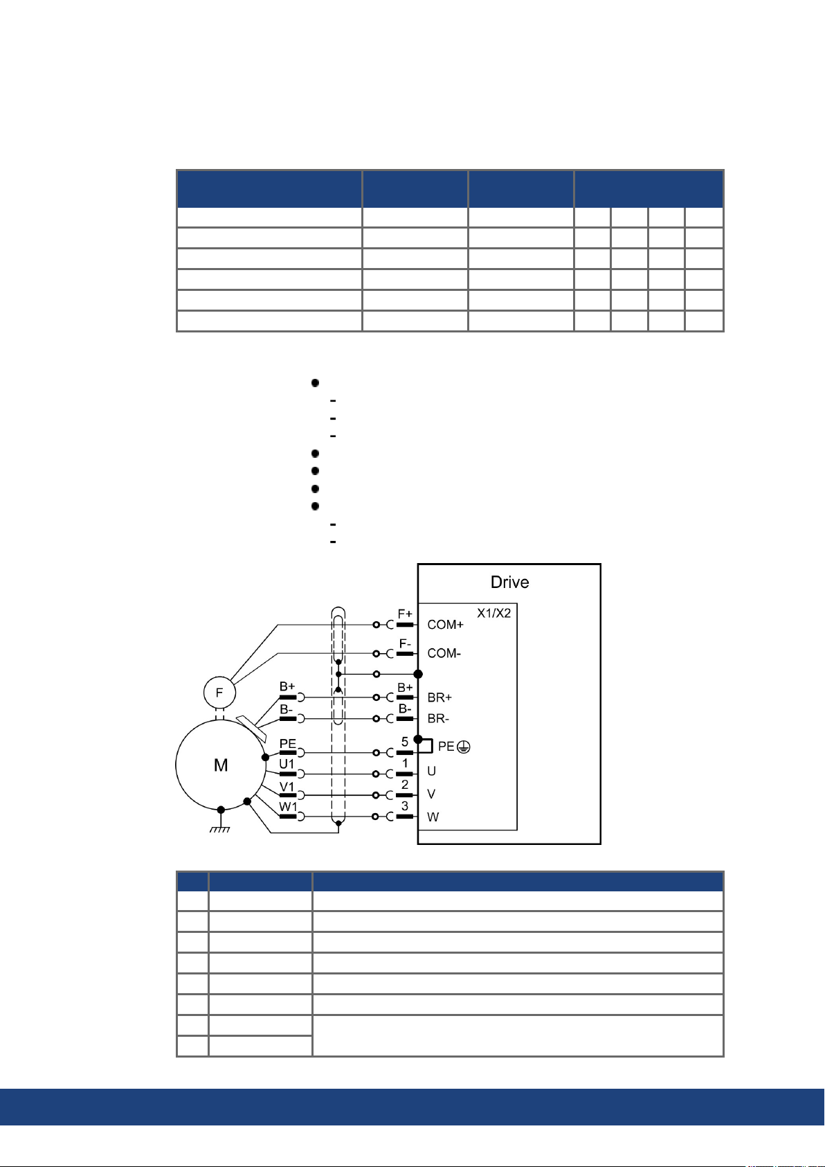
AKD2G-S Installation Manual, Safety 1 | 8 Electrical Installation
8.9.2 Motor single cable connection
Motors with two wire feedback systems like SFD3 or Hiperface DSL can be connected to
AKD2G by using a single Kollmorgen hybrid cable. Dependingon the AKD2G version (single
or dual axis), one or two singlecable motor connections are possible.
Drive type
Single axis standard X1 - - X21 - Single axis with Option I/O X1 - - X21 X22 Single axis with Option F3 X1 - - X21 - X23
Single axis with Option DX X1 - - X21 X22 X23
Dual axis standard X1 X2 - X21 X22 Dual axis with Option DX X1 X2 - X21 X22 X23
8.9.2.1 Motor Power, Brake and Feedback connectors X1, X2
X1 (Feedback 1) / X2 (Feedback 2)
Cable length: (➜ # 49)
Use Kollmorgen cables
Mating connector data (➜ # 48).
Feedback types: SFD3, HIPERFACE DSL
Commutation
Axis 1
Motor Power: 4 pin, pitch 7.62 mm
Motor Brake: 2 pin, pitch 3.81 mm
Motor Feedback: 2 pin, pitch 3.81 mm
Rated voltage 11 V.
Rated current is 350 mA simultaneously for X1 andX2.
Commutation
Axis 2
Velocity/Position loop
closure
Pinout is identical for connectors X1 and X2.
Pin Signal Description
1 U Motor phase U
2 V Motor phase V
3 W Motor phase W
5 PE Protective earth
B+ BR+ Brake positive line (safety notes and details (➜ # 84))
B- BR- Brake negative line (safety notes and details (➜ # 84))
F+ COM+
F- COM-
80 Kollmorgen | kdn.kollmorgen.com | July 2020
SFD3, HIPERFACE DSL
Page 81

8.9.2.2 Feedback connectors X21, X22, X23
Velocity/Position loopclosing
Use Kollmorgen cables
Mating connector data (➜ # 48).
Cable length: (➜ # 49)
Connector Functionality Pinout, Wiring
X21 Step/Direction, CW/CCW (➜ # 88)
X22 Step/Direction, CW/CCW, Incr.Encoder, EnDAT, BiSS (➜ # 89)
X23 Several conventional feedback types (➜ # 90)
AKD2G-S Installation Manual, Safety 1 | 8 Electrical Installation
Kollmorgen | kdn.kollmorgen.com | July 2020 81
Page 82
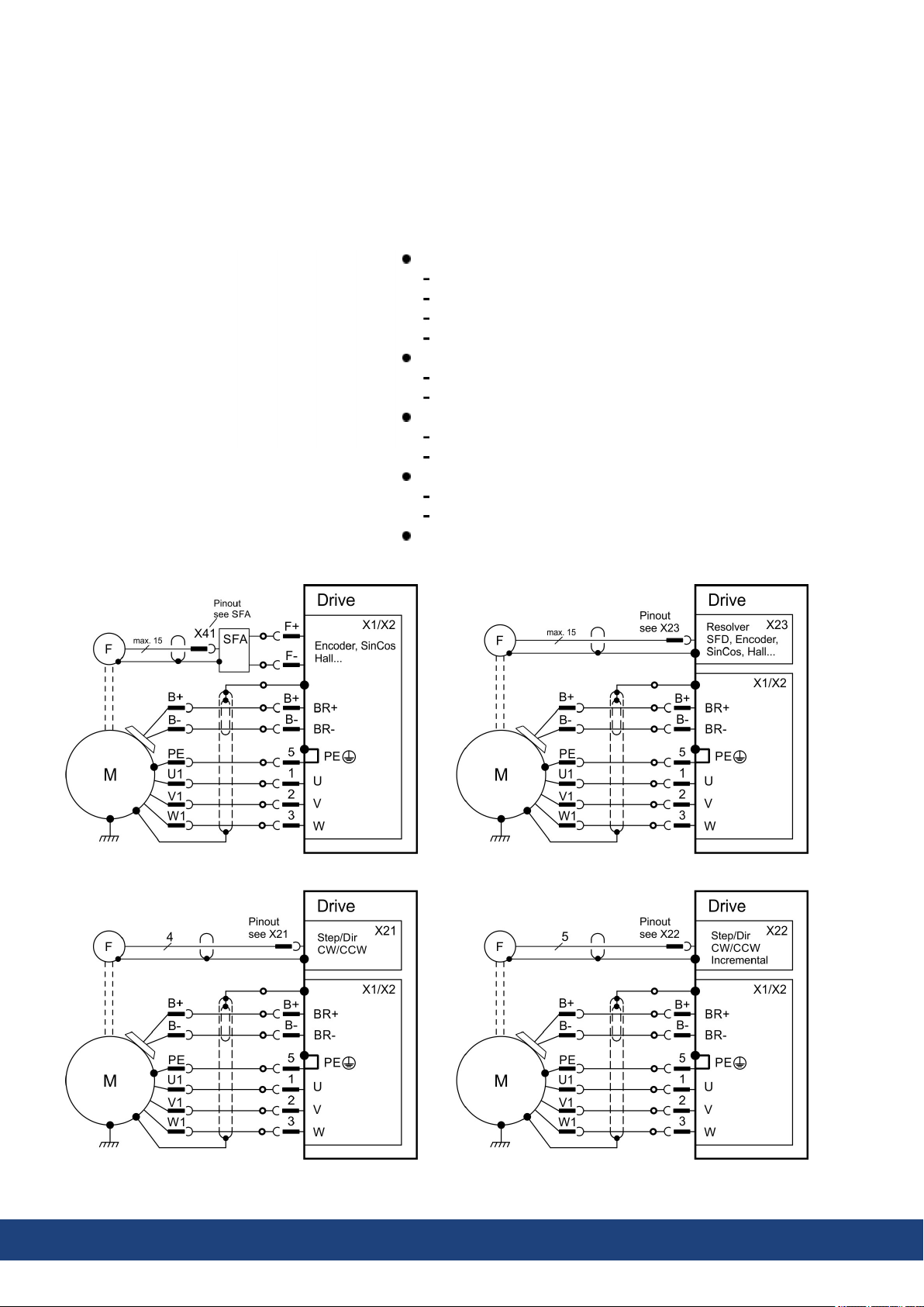
AKD2G-S Installation Manual, Safety 1 | 8 Electrical Installation
8.9.3 Motor dual cable connection
Motors with conventional commutation feedback systems like resolver or sine encoder can
be connected to AKD2G with separated power/brake and feedback cables. Feedback functions are assigned with parameters in WorkBench. Scaling and other settings are performed
in WorkBench, too. Velocity / Position loop closing and electronic gearing / master-slave connection are possible by using X21, X22, X23 depending onthe drive versionand physical
restrictions.
X1 (Feedback 1) / X2 (Feedback 2)
Motor Power: 4 pin, pitch 7.62 mm
Motor Brake: 2 pin, pitch 3.81 mm
SFA connection: 2 pin, pitch 3.81 mm
Feedback types: see SFA connectivity (➜ # 91)
X23 (Feedback 3)
SubD HD 15 poles
Feedback types: see X23 connectivity (➜ # 90)
X21 (Feedback 4)
2 x 11 pins (left connector A, right connector B)
Feedback types: see X21 connectivity (➜ # 88)
X22 (Feedback 5)
2 x 10 pins (left connector A, right connector B)
Feedback types: see X22 connectivity (➜ # 89)
Mating connector data (➜ # 48).
82 Kollmorgen | kdn.kollmorgen.com | July 2020
Page 83
AKD2G-S Installation Manual, Safety 1 | 8 Electrical Installation
8.9.3.1 Motor power and motor brake connectors X1, X2
Usually these lines are part of the Kollmorgen motorcable connected to X1 or X2. For motor
brake safety notes and functional details (➜ # 84).
Use Kollmorgen cables
Mating connector data (➜ # 48).
Cable length: (➜ # 49)
Pin Signal Description
1 U Motor phase U
2 V Motor phase V
3 W Motor phase W
5 PE Protective earth
B+ BR+ Brake positive, with Kollmorgen cables only
B- BR- Brake negative, with Kollmorgen cables only
8.9.3.2 Feedback connectors X1, X2, X41, X21, X22, X23
Use Kollmorgen cables
Mating connector data (➜ # 48).
Cable length: (➜ # 49)
For feedback connection overview (➜ # 86)
Connector Functionality
Pinout,
Wiring
X1/X2 SFD3, DSL, SFA (➜ # 87)
X41 SFA at X1 or X2 , several conventional feedback types (➜ # 91)
X21 Step/Direction, CW/CCW (➜ # 88)
X22 Step/Direction, CW/CCW, Incr. Encoder, EnDAT, BiSS (➜ # 89)
X23 Several conventional feedback types (➜ # 90)
Feedback connector X1, X2, X41
Conventional feedback systems can be connected to X1 or X2 by using the optional feedback adapter SFA. SFA offers the additional connector X41.
Connector X1 is a standard connector. Input for SFD3, DSL, or SFA.
Connector X2 is standard for dual-axis drives. Input for SFD3, DSL, or SFA.
SFA: adapter for several conventional feedback types
Feedback connector X21
Connector X21 is a standardconnector.
Input for Step/Direction and CW/CCW.
Feedback connector X22
Connector X22 is standard connector for dual-axis drives.
Connector X22 is part of option DX or IO for single axis drives.
Input for Step/Direction, CW/CCW, Incremental encoder
Feedback connector X23
Connector X23 is part of option DX or F3.
Input for several conventional feedback types.
Kollmorgen | kdn.kollmorgen.com | July 2020 83
Page 84
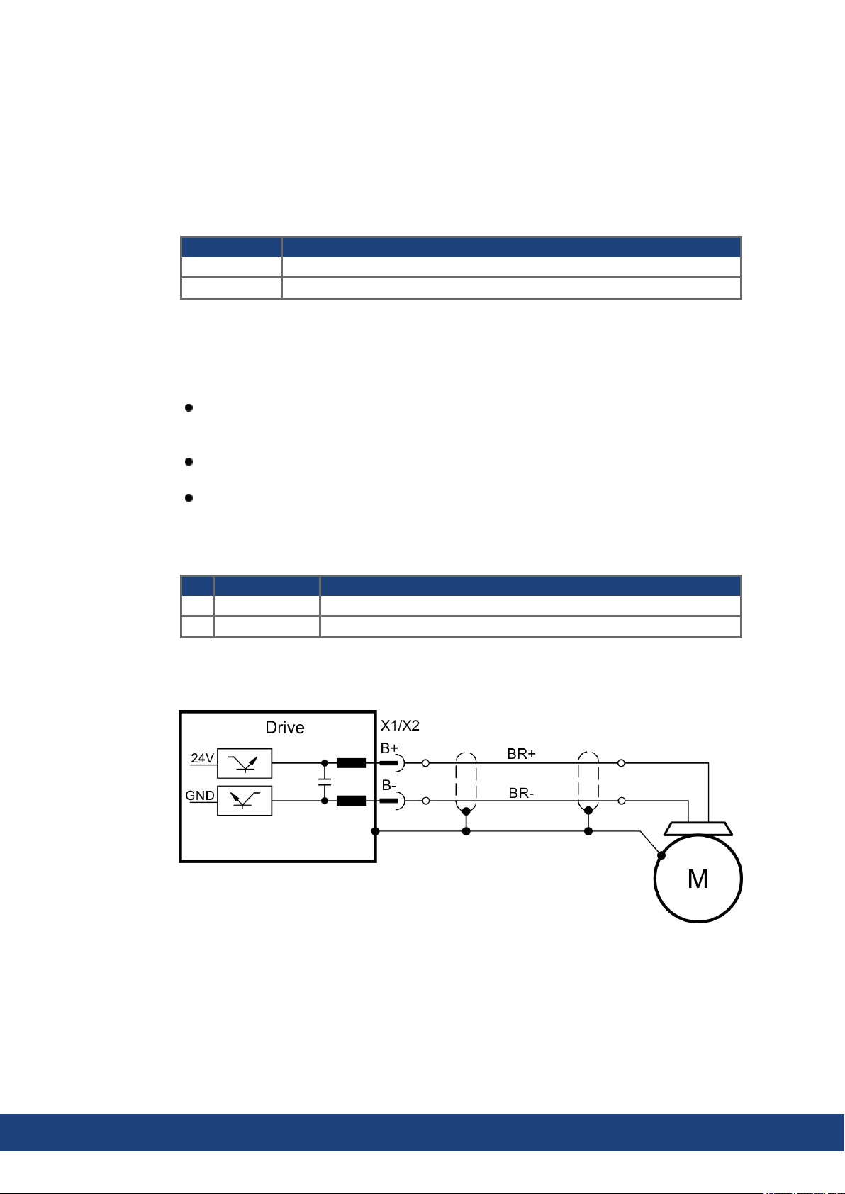
AKD2G-S Installation Manual, Safety 1 | 8 Electrical Installation
8.9.4 Motor Holding Brake Connection
A 24 V holding brake in the motor can be controlled directly by the drive. For properfunction,
check voltage drop, measure voltage at brake input and check brake function (on and off).
Brake voltage supply by using 24 V ±10% auxiliary voltagesupply of the drive on X10. Minimum and maximum brake current see Electrical Data (➜ # 34) respectively (➜ # 36).
AKD2G offers motor brake outputs on connectors X1 andX2. The outputs can be mapped to
the required axis with WorkBench.
Connector Usable for
X1 Primary motor brake axis 1 or secondary brake for axis 2
X2 Primary motor brake axis 2 or secondary brake for axis 1
No functional Safety!
Serious injury could result when the load is not properly blocked. The internal brake function
does not ensure functional safety.
Functional safety, e.g. with hanging load (vertical axes), requires an additional brake,
controlled e.g. from the other axis or externally from a safety controller. The brakes can
be mappedto an axis with WorkBench.
The Hardware Enable does not initiate a controlledstop but switches off the power stage
immediately.
Set parameter AXIS#.MOTOR.BRAKEIMM to 1 with vertical axes, to apply the brake
immediately after faults or Hardware Disable.
Pinout X1 / X2
Pin Signal Description
B+ BR+ Brake positive line
B- BR- Brake negative line
Wiring
Usually the brake lines arepart of the Kollmorgen hybrid single cable connection to X1
respectively X2 (➜ # 80).
84 Kollmorgen | kdn.kollmorgen.com | July 2020
Page 85
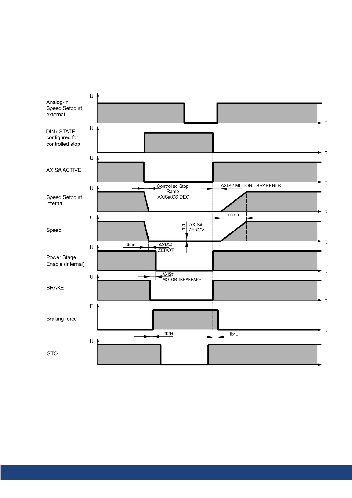
AKD2G-S Installation Manual, Safety 1 | 8 Electrical Installation
Functionality
The brake function must be enabled through a parameter. The diagram below shows the timing and functional relationships between the controlledstop signal, speed, and braking force.
All values can be adjusted with parameters; values in the diagram are default values.
The drive speed setpoint is internally driven down an adjustable ramp (AXIS#.CS.DEC) to
0V.
With default values the output for the brake is switched on when the speed has reached
5rpm (AXIS#.ZEROV) for at least 6ms (AXIS#.ZEROT). The rise (t
) and fall (t
brH
) times of
brL
the holding brake that is built into the motor are different for the various types of motor.
Kollmorgen | kdn.kollmorgen.com | July 2020 85
Page 86
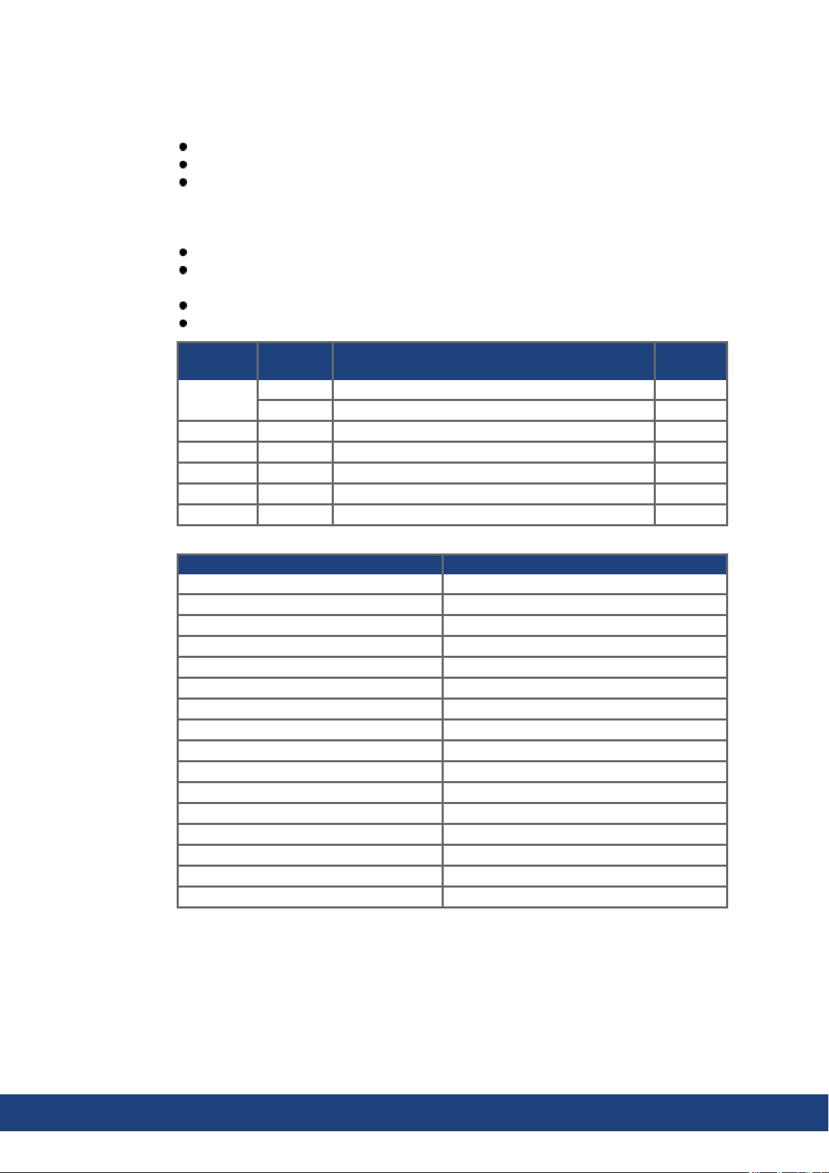
AKD2G-S Installation Manual, Safety 1 | 8 Electrical Installation
8.9.5 Feedback Connection
AKD2G offers up to five feedback channels. These channels can serve
to commutate the motor (single cable (➜ # 80)or dual cable (➜ # 84)),
to close the velocity and/or position loops, and
to act as a command source (electronic gearing, flying sheer, master-slave (➜ # 92)).
The usage of the five channels may be freely configuredin software, subject only to a few
restrictions that are not physically sensible.
Exactly one feedback channel peraxis can commutate the motor.
At most onefeedback channel per axis can serve as the command source and the same
feedback channel cannot also commutate the motor.
A feedback channel can serve as the command source for more than one axis.
FB1 cannot commutate axis 2. FB2 cannot commutate axis 1.
Feedback
channel
Feedback 1
Feedback 2 X2 Axis 2: commutation feedback (➜ # 87)
Feedback 2 X41 Axis 2 by using SFA on X2: commutation feedback (➜ # 91)
Feedback 3 X23 commutation feedback, velocity/position, command (➜ # 90)
Feedback 4 X21 commutation feedback, velocity/position, command (➜ # 88)
Feedback 5 X22 commutation feedback, velocity/position, command (➜ # 89)
Feedback Types Connectors
SFD3 X1, X2
Encoder HIPERFACE DSL X1, X2
Resolver X23, X41
SFD X23, X41
SinCos Encoder BiSS B (analog) X22, X23, X41
Encoder BiSS C (digital) X22, X23
SinCos Encoder EnDat 2.1 X23, X41
Encoder EnDat Digital 2.2 X22, X23, X41
Encoder HIPERFACE X23, X41
Sine Encoder X23, X41
Sine Encoder + Hall X23, X41
Incremental Encoder X22, X23, X41
Incremental Encoder + Hall (Comcoder) X23, X41
Hall Sensors X23, X41
Step/Direction X21, X22, X23, X41
CW/CCW X21, X22, X23, X41
Connector Usable for Pinout
X1 Axis 1: commutation feedback (➜ # 87)
X41 Axis 1 by using SFA on X1: commutation feedback (➜ # 91)
86 Kollmorgen | kdn.kollmorgen.com | July 2020
Page 87
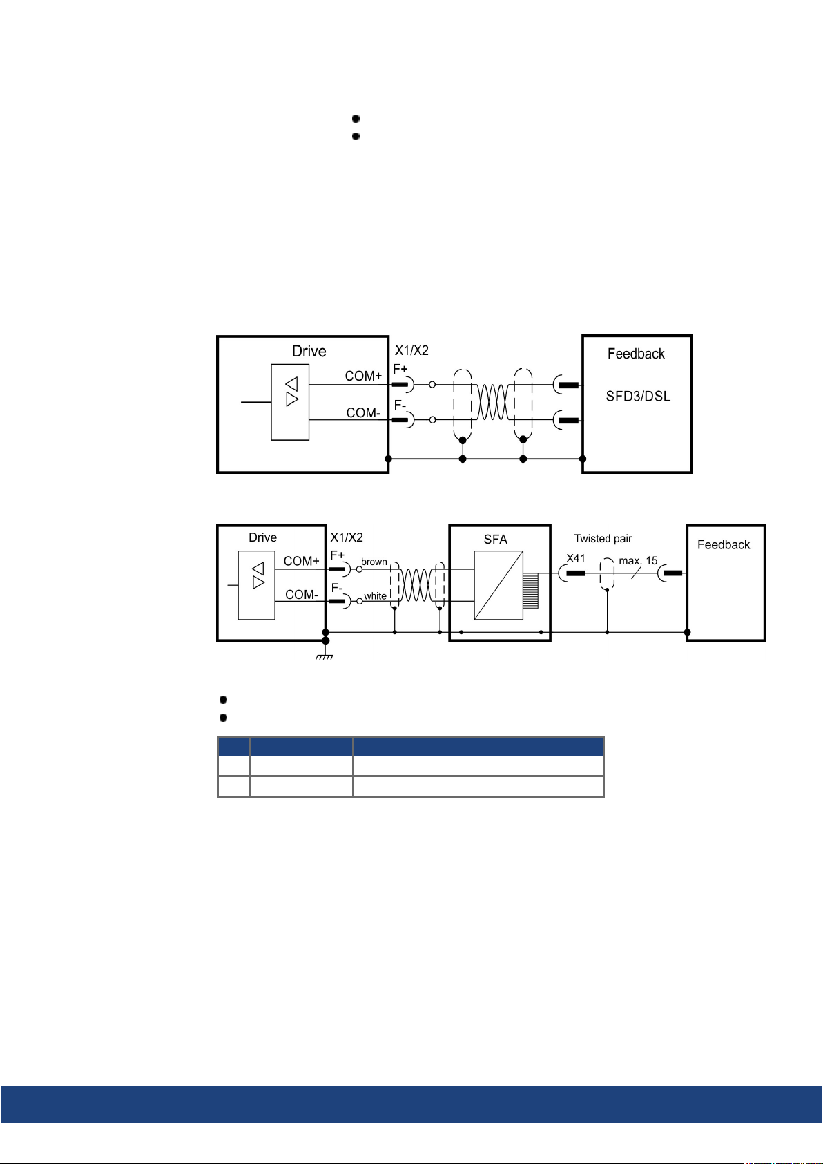
8.9.5.1 Feedback Connector X1, X2
Wiring example SFD3 or HIPERFACE DSL
AKD2G-S Installation Manual, Safety 1 | 8 Electrical Installation
4 pin, pitch 7.62 mm plus 2x2 pin pitch 3.81 mm
Input for commutation feedback: SFD3, DSL, SFA
Wiring example conventional Feedback types with SFA
Electrical data
Rated voltage 11 V.
Rated current is 350 mA simultaneously for X1 andX2.
Pin Signal Description
F+ COM+ SFD3 +, HIPERFACE DSL +, SFA +
F- COM- SFD3 -, HIPERFACE DSL -, SFA -
Kollmorgen | kdn.kollmorgen.com | July 2020 87
Page 88
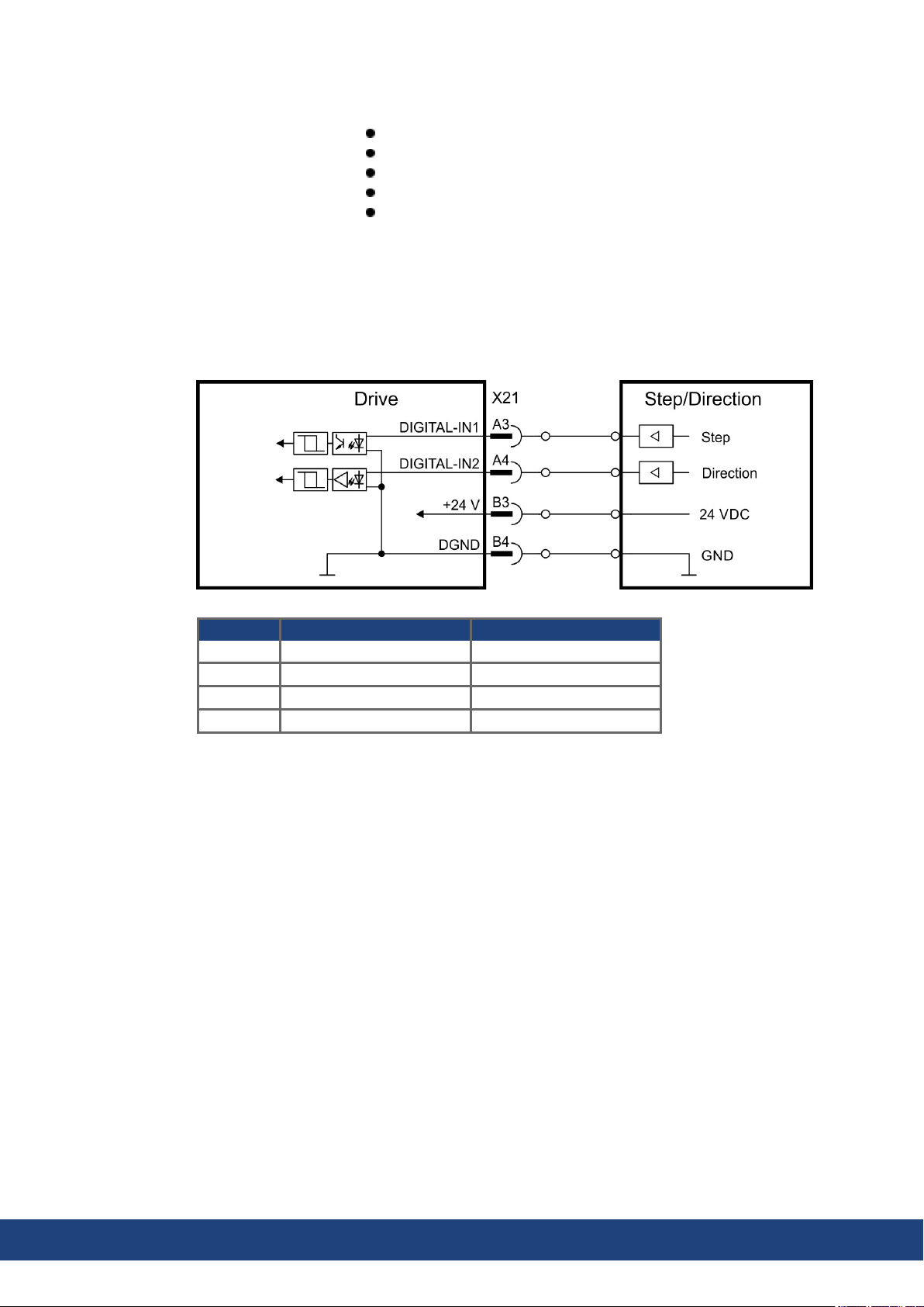
AKD2G-S Installation Manual, Safety 1 | 8 Electrical Installation
8.9.5.2 Feedback Connector X21
2 x 11 pins (left connector A, right connector B), pitch 3.5 mm
Fast input, isolated, sink, type EN 61131-2 type 1
Input for commutation or position feedback.
Input for Electronic Gearing, (➜ # 92)
Mating connector data (➜ # 48).
Wiring example
X21 Pin Step/Direction CW/CCW
A3 Step CW
A4 Direction CCW
B3 24 VDC 24 VDC
B4 Common (DGND) Common(DGND)
88 Kollmorgen | kdn.kollmorgen.com | July 2020
Page 89
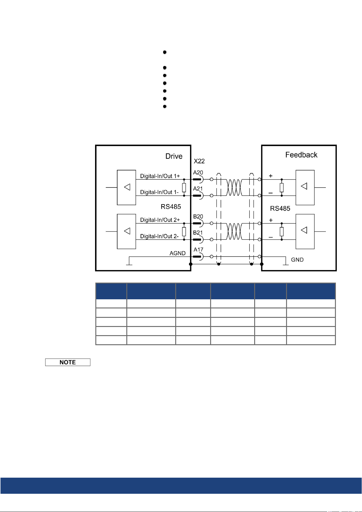
8.9.5.3 Feedback Connector X22
Wiring example (Input)
AKD2G-S Installation Manual, Safety 1 | 8 Electrical Installation
Standard for dual axis drives, (➜ # 27), optional for single axis
drives
2 x 10 pins (left connector A, right connector B), pitch 3.5 mm
RS485 inputs
Input for commutation or position feedback.
Input for Electronic Gearing, (➜ # 92)
Output for encoderemulation (EEO2), (➜ # 92)
Mating connector data (➜ # 48).
EEO output connection is similar.
X22 Pin
Step /
Direction
CW /
CCW
Increm.
Encoder
BiSS
B / C
A20 Step + CW + Track A + CLK+ CLK+
A21 Step - CW - Track A - CLK- CLKB20 Direction + CCW + Track B + DAT+ DAT+
B21 Direction - CCW - Track B - DAT- DATA17 AGND AGND AGND AGND AGND
Feedback power supply must be supplied and controlled by the user.
EnDAT 2.2
Kollmorgen | kdn.kollmorgen.com | July 2020 89
Page 90
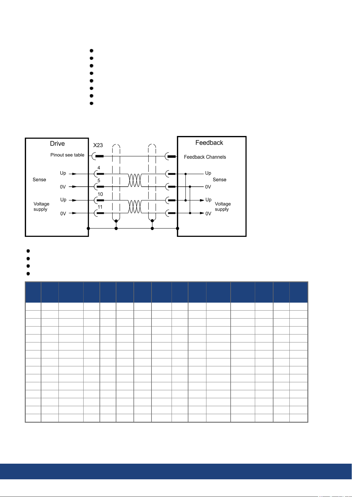
AKD2G-S Installation Manual, Safety 1 | 8 Electrical Installation
8.9.5.4 Feedback Connector X23
Connectivity Option F3 or DX (➜ # 27)
Sub-D highdensity 15 pin, female
Use Kollmorgen feedback cables
Input for several feedback types
Input for Electronic Gearing, (➜ # 92)
Output for encoderemulation (EEO1), (➜ # 92)
Digital input (➜ # 107), Digital output (➜ # 111)
Mating connector data (➜ # 48).
Encoder power supply (X23 pins 10/11):
Maximum voltage 9 V with shorted sense contacts (4/5), ratedvoltage5 V +/-5%.
Rated supply current is 350 mA.
Voltagerise time ~4 ms with full loadand 220 µF of capacitance.
Encoder powerlines capacitance 10 µF to 220 µF
X23
SFD
Pin
1 - - - - - - - - HallU - HallU HallU - 2 - - CLK+ CLK+ CLK+ CLK+ - - HallV - HallV HallV - 3 - - CLK- CLK- CLK- CLK- - - HallW - HallW HallW - 4 SEN+ - SEN+ SEN+ SEN+ SEN+ SEN+ SEN+ SEN+ SEN+ SEN+ - - 5 SEN- - SEN- SEN- SEN- SEN- SEN- SEN- SEN+ SEN+ SEN+ - - 6 COM+ R1 Ref+ DAT+ DAT+ DAT+ DAT+ DAT+ Zero+ Zero+ Zero+ Zero+ - - 7 COM- R2 Ref- DAT- DAT- DAT- DAT- DAT- Zero- Zero- Zero- Zero- - - 8 - Th+ Th+ - Th+ - Th+ Th+ Th+ Th+ Th+ Th+ Th+ Th+
9 - Th- Th- - Th- - Th- Th- Th- Th- Th- Th- Th- Th10 +5 V - +5 V +5 V +5 V +5 V +5 V +5 V +5 V +5 V +5 V +5 V +5 V +5 V
11 0 V - 0 V 0 V 0 V 0 V 0 V 0 V 0 V 0 V 0 V 0 V 0 V 0 V
12 - S1SIN+ A+ - A+ - SIN+ A+ A+ A+ A+ - Step+ CW+
13 - S3SIN- A- - A- - SIN- A- A- A- A- - Step- CW14 - S2COS+ B+ - B+ - COS+ B+ B+ B+ B+ - Dir+ CCW+
15 - S4COS- B- - B- - COS- B- B- B- B- - Dir- CCW-
Resol-
ver
BiSSBBiSSCEnDat
2.1
EnDat
2.2
HIPER-
FACE
Sine/
Cos
Sine/
Cos
+Hall
Incr.
Enc.
Incr.
Enc.
+Hall
Hall
Step/
Dir
CW/
CCW
CLK = CLOCK, DAT = DATA, SEN = SENSE, Th = Thermal control
90 Kollmorgen | kdn.kollmorgen.com | July 2020
Page 91
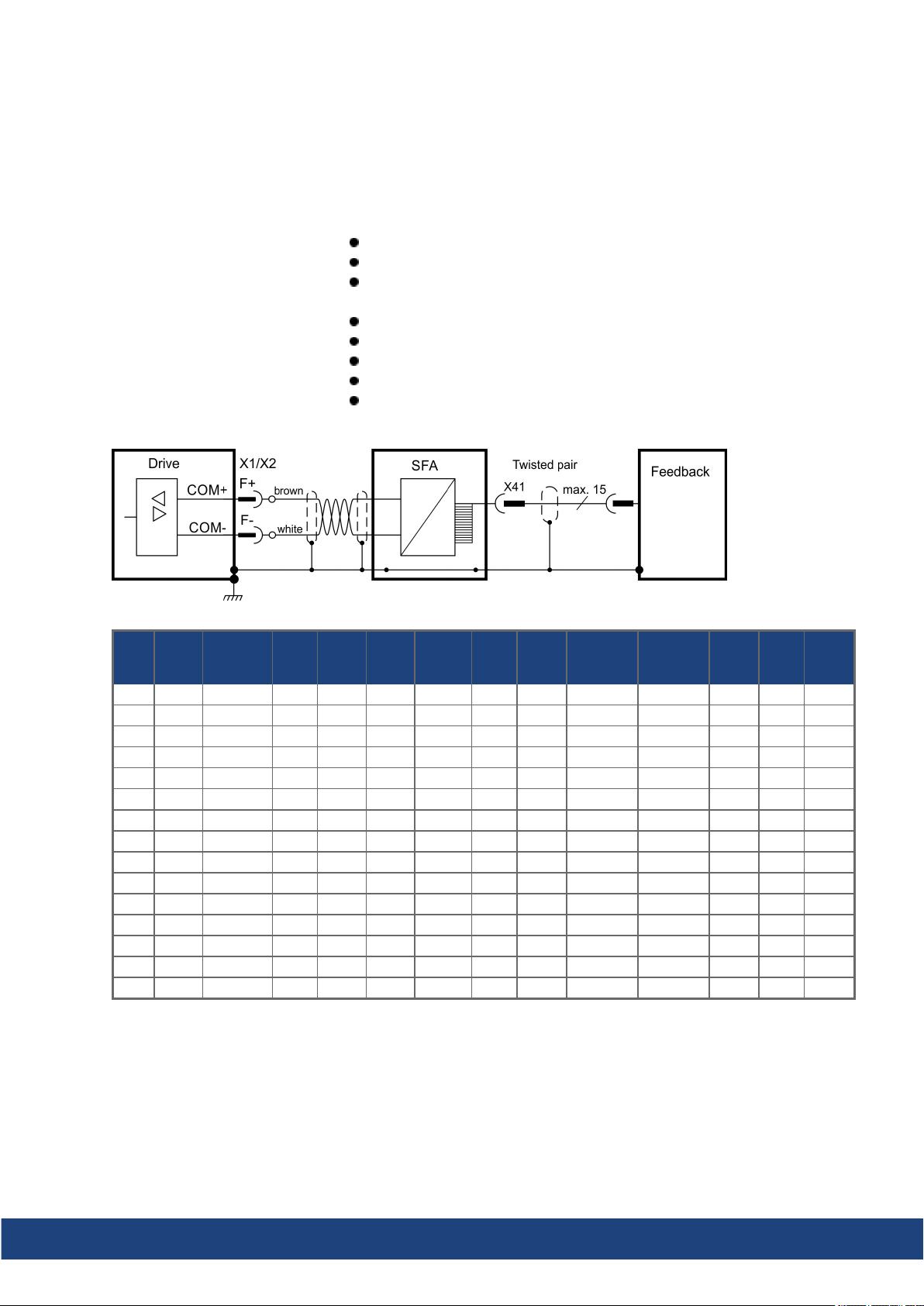
AKD2G-S Installation Manual, Safety 1 | 8 Electrical Installation
8.9.5.5 Feedback Connector X41 (SFA, accessory)
SFA (Smart Feedback Adapter) converts conventional feedback signals to a 2-wire serial signal. SFA can be laid
into the cable duct or may be mounted to a DIN rail using a standard DIN rail clip.
SFA adds a 15 pole HD SubD female connector X41 to the system for connection of a Kollmorgen motor feedback cable (see Kollmorgen 2G Cable Guide). Dimensions (LxWxD): 88.6 x 55.6 x 21.2 (28.6 with rail clip). Order
codes see regional Accessories Manual.
Sub-D highdensity 15 pin, female
1 m shielded cable with 3 flying leads for connection to X1 or X2
The cable shieldis connected with cable ties to the X1/X2 shield plates
(cut-off the unusedshield wire).
Connected feedback must be set in WorkBench
Use Kollmorgen feedback cables
Input for Electronic Gearing, (➜ # 92)
Output for encoderemulation (EEO3/EEO4), (➜ # 92)
Master-Slave (➜ # 94)
Connect the flying leads of the SFA cable to X1 (FB1, EEO3) or X2 (FB2, EEO4):
Operating Voltage: 7 V to 12 V, Maximum Load Current: 350 mA
Cos
Sine/
Cos
+Hall
Incr. Enc.
Incr. Enc.
+Hall
Hall
Step/
Dir
X41
SFD
Pin
1 - - - - - - - HallU - HallU HallU - 2 - - CLK+ CLK+ CLK+ - - HallV - HallV HallV - 3 - - CLK- CLK- CLK- - - HallW - HallW HallW - 4 SEN+ - SEN+ SEN+ SEN+ SEN+ SEN+ SEN+ SEN+ SEN+ - - 5 SEN- - SEN- SEN- SEN- SEN- SEN- SEN+ SEN+ SEN+ - - 6 COM+ R1 Ref+ DAT+ DAT+ DAT+ DAT+ Zero+ Zero+ Zero+ Zero+ - - 7 COM- R2 Ref- DAT- DAT- DAT- DAT- Zero- Zero- Zero- Zero- - - 8 - Th+ Th+ Th+ - Th+ Th+ Th+ Th+ Th+ Th+ Th+ Th+
9 - Th- Th- Th- - Th- Th- Th- Th- Th- Th- Th- Th10 +5 V - +5 V +5 V +5 V +5 V +5 V +5 V +5 V +5 V +5 V +5 V +5 V
11 0 V - 0 V 0 V 0 V 0 V 0 V 0 V 0 V 0 V 0 V 0 V 0 V
12 - S1SIN+ A+ A+ - SIN+ A+ A+ A+ A+ - Step+ CW+
13 - S3SIN- A- A- - SIN- A- A- A- A- - Step- CW14 - S2COS+ B+ B+ - COS+ B+ B+ B+ B+ - Dir+ CCW+
15 - S4COS- B- B- - COS- B- B- B- B- - Dir- CCW-
CLK = CLOCK, DAT = DATA, SEN = SENSE, Th = Thermal control
Resol-
ver
BiSSBEnDat
2.1
EnDat
2.2
HIPER-
FACE
Sine/
CW/
CCW
Kollmorgen | kdn.kollmorgen.com | July 2020 91
Page 92
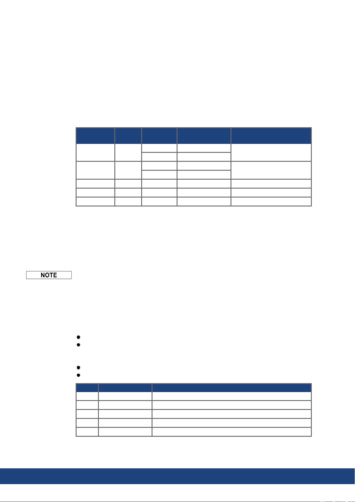
AKD2G-S Installation Manual, Safety 1 | 8 Electrical Installation
8.10 EEO, Electronic Gearing, Master-Slave
AKD2G offers up to 5 feedback channels,
which may be used as the command source
(input) for electronic gearing or master-slave
or for EEO (Emulated Encoder Output).
Feedback
channel
Feedback 1 EEO3
Feedback 2 EEO4
Feedback 3 EEO1 X23 (➜ # 90) FB3.SELECT
Feedback 4 n/a X21 (➜ # 88) FB4.SELECT
Feedback 5 EEO2 X22 (➜ # 89) FB5.SELECT
EEO
channel
8.10.1 Emulated Encoder Output (EEO)
The drive calculates the motor shaft position from the cyclic- absolute signals of the commutation feedback, generating incremental-encodercompatible pulses or CW/CCW signals
or Pulse/Direction signals from this information.
The resolution and the index (zero) position can be set in WorkBench. The outputs are driven
from an internal supply voltage. Refer to the WorkBench Online Help for more information.
When using a multispeed resolver (morethan 2 poles) as commutationfeedback, the EEO
will create only one zeropulse per each mechanical revolution of the motor. The zeropulse
is dependent on the motors starting position!
EEO1-4 are NOT compatible with 24V signal level! Will be damaged if connected to +24V!
Connector
X1 (➜ # 87)
X41 (➜ # 91)
X2 (➜ # 87)
X41 (➜ # 91)
Pinout and
wiring example
Parameter to configure
the sensor type
FB1.SELECT
FB2.SELECT
Technical characteristics X22, EEO2
Pulse outputs on the connector X22 are 2 signals, tracks A and B, with 90° phase difference
(i.e. in quadrature, hence the alternative term “AquadB” output).
RS-485, current 100mA
Max. number of connected slaves is determined by the loading characteristics of the
slaves. 32 slaves can be driven if the input impedance of the bias network is 10kΩ and
only one slave has a DC termination resistor.
Max signal (channel)output frequency: 3 MHz
The pulses perrevolution valueis settable, pulse phase shift: 90°±20°
X22 Signals EEO2 Description
A17 AGND Analogground
A20 Track A+ EEO2 output, channel A positive
A21 Track A- EEO2 output, channel A negative
B20 Track B+ EEO2 output, channel B positive
B21 Track B- EEO2 output, channel B negative
92 Kollmorgen | kdn.kollmorgen.com | July 2020
Page 93
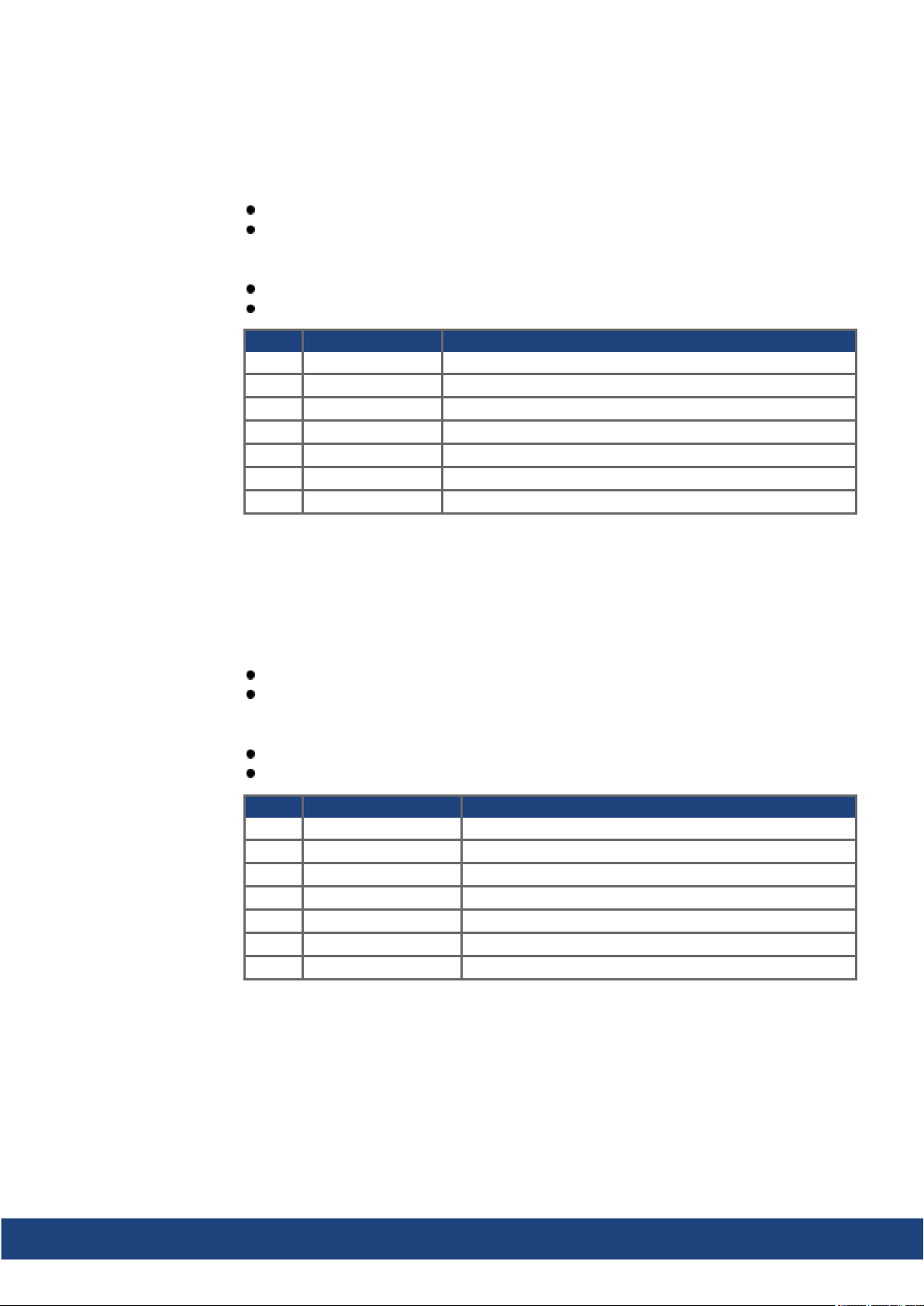
AKD2G-S Installation Manual, Safety 1 | 8 Electrical Installation
Technical characteristics X23, EEO1
Pulse outputs on the SubD connector X23 are 3 signals, A, B and Index, with 90° phase difference (i.e. AquadB), with a zero pulse.
5V TTL, current 60 mA
Max. number of connected slaves is determined by the loading characteristics of the
slaves, 32 slaves can be driven if the input impedance of the bias network is 10kΩ and
only one slave has a DC termination resistor.
Max signal (channel)output frequency: 3 MHz
The pulses perrevolution valueis settable, pulse phase shift: 90°±20°
X23 Signals EEO1 Description
6 Zero+ EEO1 output, index positive
7 Zero- EEO1 output, index negative
11 0 V EEO1 output, ground
12 Track A+ EEO1 output, channel A positive
13 Track A- EEO1 output, channel A negative
14 Track B+ EEO1 output, channel B positive
15 Track B- EEO1 output, channel B negative
Technical characteristics X41 (SFA), EEO3/EEO4
Pulse outputs on the SubD connector X41 are 3 signals, A, B and Index, with 90° phase difference (i.e. “AquadB”), with a zero pulse.
If SFA is connected to X1, the logical output is EEO3.
If SFA is connected to X2 or X5, the logical output is EEO4.
5V TTL, current 60 mA
Max. number of connected slaves is determined by the loading characteristics of the
slaves, 32 slaves can be driven if the input impedance of the bias network is 10kΩ and
only one slave has a DC termination resistor.
Max signal (channel)output frequency: 3 MHz
The pulses perrevolution valueis settable, pulse phase shift: 90°±20°
X41 Signals EEO3/EEO4 Description
6 Zero+ EEO3/EEO4 output, index positive
7 Zero- EEO3/EEO4 output, index negative
11 0 V EEO3/EEO4 output, ground
12 Track A+ EEO3/EEO4 output, channel A positive
13 Track A- EEO3/EEO4 output, channel A negative
14 Track B+ EEO3/EEO4 output, channel B positive
15 Track B- EEO3/EEO4 output, channel B negative
Kollmorgen | kdn.kollmorgen.com | July 2020 93
Page 94
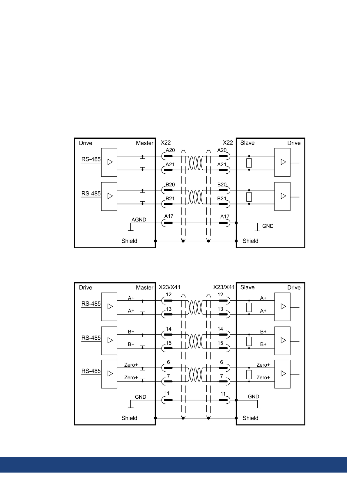
AKD2G-S Installation Manual, Safety 1 | 8 Electrical Installation
8.10.2 Electronic Gearing
AKD2G offers up to 5 feedback channels. Any of these channels may be used as the gearing
command source. The gearing source is selected for each axis using
AXIS#.GEAR.FBSOURCE. Refer to the WorkBench Online Help for more information.
8.10.3 Master-Slave control
Several AKD2G can be connected as slave drives to another AKD2G which acts as a master. The slave drives use the master's encoder output signal (EEO, (➜ # 92)) as command
input and follow these commands (velocity and direction).
8.10.3.1 Master-Slave using X22
The master is configured for EEO2 (➜ # 92) on X22, the Slave uses X22 for command input.
8.10.3.2 Master-Slave using optional X23 or X41
The master is configured for EEO1 (➜ # 93) on X23 or EEO3/EEO4 ((➜ # 93)with SFA) on
X41, the Slave uses X23 (or X41 with SFA) for command input.
94 Kollmorgen | kdn.kollmorgen.com | July 2020
Page 95
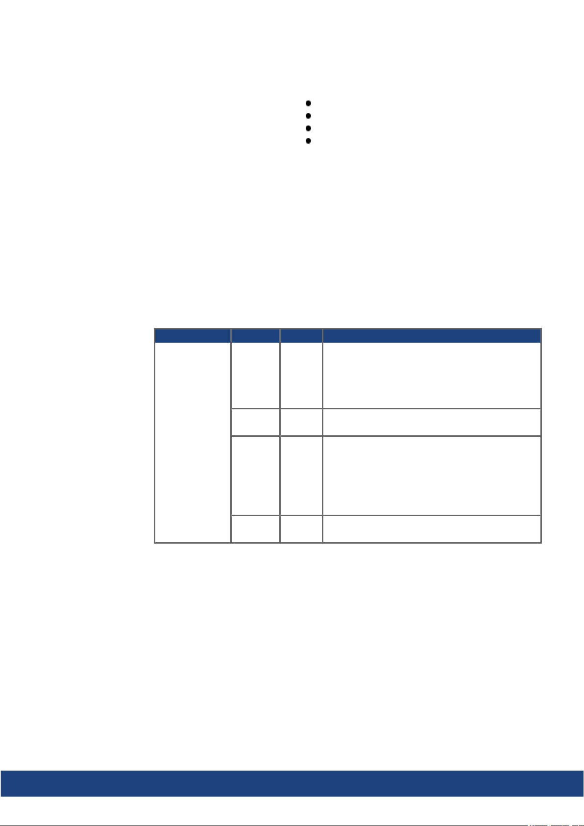
AKD2G-S Installation Manual, Safety 1 | 8 Electrical Installation
8.11 EtherNet Fieldbus Interface (X11/X12)
The EtherNet Fieldbus interface has two RJ-45 connectors.
Do not connect the Service line for the PC with the set up softwareto the EtherNet Fieldbus
interface X11/X12. The service EtherNet cable must be connected to X20.
EtherNet Fieldbus interface X11/X12 pinout depends on the used protocol. Refer to the
matching fieldbus communicationmanual.
8.11.1 EtherCAT®
AKD2G drives (connectivity option E) can be connected as slaves to the EtherCAT® network (CoE) by using RJ-45 connectors X11 (out port) and X12 (in port). The communication
status is indicated by the built-in connector LEDs.
RJ-45 with built-in green/red dual-colorLED.
EtherCAT®
EtherNet/IP*
PROFINET*
* available 2021
Conn. Name Function
X11 „Out“ „ERR“ Returns potentials communication failures:
Off = No Error
Blinking = Invalid configuration
Single Flash = Local error
DoubleFlash = Process data watchdog
X11 „Out” Link/
Activity
X12 „In“ „RUN“ Returns the device state:
X12 „In” Link/
Activity
Bus topology example (EtherCAT®)
We suggest to use Kollmorgen ENCP cables. For more possible system solutions refer to
the WorkBench Online Help.
On/Blinking: Physical link/Data Traffic on.
Static off: No link.
Off = INIT
Blinking = PRE-OPERATIONAL
Single Flash = SAFE-OPERATIONAL
On = OPERATIONAL
Flickering = Initialization or BOOTSTRAP
On/Blinking: Physical link/Data Traffic on.
Static off: No link.
Communication profile
For EtherCAT® communication profile description refer to the manual "AKD2G EtherCAT®
Communication".
Kollmorgen | kdn.kollmorgen.com | July 2020 95
Page 96
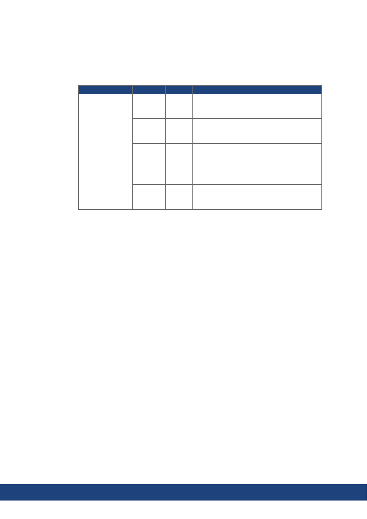
AKD2G-S Installation Manual, Safety 1 | 8 Electrical Installation
8.11.2 PROFINET (available 2021)
AKD2G with connectivity option P can be connected as slaves to a PROFINET network by
using RJ-45 connectors X11 (Port 2) and X12 (Port 1). PROFINET RT or IRT protocols can
be used. The communication status is indicated by the built-in connector LEDs.
The field bus address must either be set automatically or by using the memory card.
Conn. Name Function
X11
Port 2
X11
Port 2
X12
Port 1
X12
Port 1
BF ON = No Configuration, low speed, no link
Link/
Activity
SF ON = Watchdog timeout; channel / generic /
Link/
Activity
OFF = No Error
Flashing 2Hz = No data exchange
ON = Connection to the EtherNet
OFF = No connection to the EtherNet
Flashing = Sends/receives EtherNet frames
extended diagnosis present; system error
OFF = No Error
Flashing 2Hz = DCP signal service is initiated
via the bus
ON = Connection to the EtherNet
OFF = No connection to the EtherNet
Flashing = Sends/receives EtherNet frames
Bus topology example (PROFINET)
We suggest to use Kollmorgen ENCP cables. For more possible system solutions refer to
the WorkBench Online Help.
Communication profile
For PROFINET communication profile description refer to the manual "AKD2G PROFINET
Communication".
96 Kollmorgen | kdn.kollmorgen.com | July 2020
Page 97
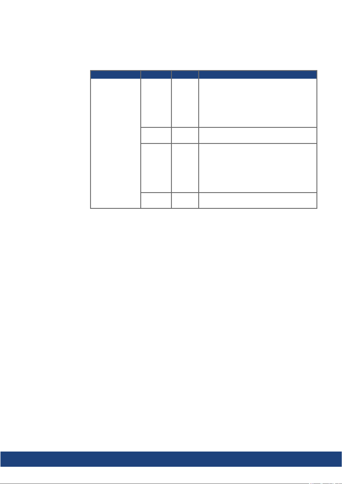
8.11.3 EtherNet/IP (available 2021)
AKD2G with connectivity option I can be connected as slaves to a EtherNet/IP network by
using RJ-45 connectors X11 (Port 2) and X12 (Port 1). The communication status is indicated by the built-in connector LEDs.
AKD2G-S Installation Manual, Safety 1 | 8 Electrical Installation
Conn. Name Function
X11
Port 2
X11
Port 2
X12
Port 1
X12
Port 1
NS Green - On = Connected
Green - Flashing = No connections
Red - On = Duplicate IP
Red Flashing = Connection Timeout
Red/GreenFlashing = Self-test
Off = No power, No IP Address
Link/
Activity
MS Green- On = Device Operational
Link/
Activity
On/Blinking: Physical link/Data Traffic on.
Static off: No link.
Green - Flashing = Standby
Red - On = Major Fault
Red Flashing = Minor Fault
Red/GreenFlashing = Self-test
Off = No power
On/Blinking: Physical link/Data Traffic on.
Static off: No link.
Bus topology example (EtherNet/IP)
We suggest to use Kollmorgen ENCP cables. For more possible system solutions refer to
the WorkBench Online Help.
Communication profile
For EtherNet/IP communication profile descriptionrefer to the manual "AKD2G EtherNet/IP
Communication".
Kollmorgen | kdn.kollmorgen.com | July 2020 97
Page 98
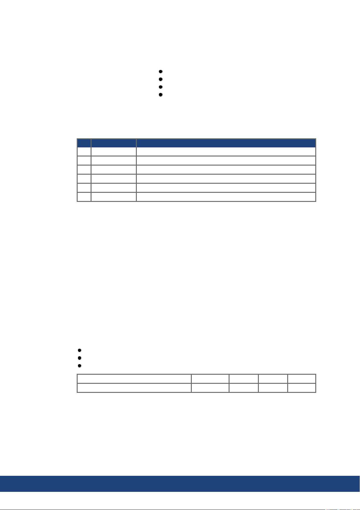
AKD2G-S Installation Manual, Safety 1 | 8 Electrical Installation
8.12 CAN-Bus Interface (X13/X14)
AKD2G drives with connectivity option C can be connected to a CAN-Bus by using two 6-pin
RJ25 connectors X13/X14.
RJ25
Up to 1000 kbit/s operation
Node ID to be set by WorkBench
Baudrate to be set by WorkBench
Pin Signal Description
1 Termination Internal Termination Resistor
2 Shield Chassis
3 CAN_high CAN bus high signal
4 CAN_low CAN bus low signal
5 CAN_GND CAN bus ground
6 Termination Internal Termination Resistor
8.12.1 CAN-Bus Topology
We recommend the use of KollmorgenCBP000 cables.
Cable requirements
To meet ISO 11898, a bus cablewith a characteristic impedance of 120 Ω should be used.
The maximum usable cable length for reliable communicationdecreases with increasing
transmission speed.
As a guide, you can use the following values measured by Kollmorgen; however, these values are not assured limits:
Characteristic impedance: 100–120 Ω
Cable capacitance max.: 60 nF / 1000 m
Lead loopresistance: 159.8 Ω / 1000 m
Transmission Rate (kBaud) 1000 500 250 125
Maximum Cable Length (m) 25 100 250 500
Lowercablecapacitance (max. 30 nF / 1000 m) andlower lead resistance (loop resistance,
115Ω / 1000 m) allow larger distances. The characteristic impedance 150 ± 5 Ω requires terminating resistor 150 ± 5 Ω.
Communication profile
For CANopen communication profile descriptionrefer to the manual "AKD2G CAN-Bus Communication".
98 Kollmorgen | kdn.kollmorgen.com | July 2020
Page 99
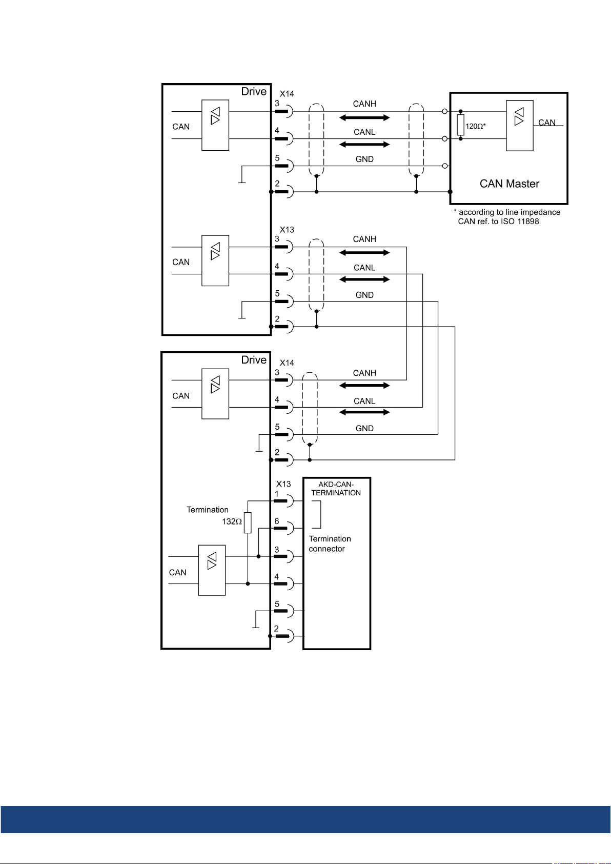
8.12.2 CAN-Bus Wiring
AKD2G-S Installation Manual, Safety 1 | 8 Electrical Installation
Kollmorgen | kdn.kollmorgen.com | July 2020 99
Page 100
AKD2G-S Installation Manual, Safety 1 | 8 Electrical Installation
8.12.3 Baud rate for CAN-Bus
The transmission rate can be set by using the parameter CANBUS.BAUD in WorkBench.
Baud rate [kBit/s] CANBUS.BAUD
125 125 (default)
250 250
500 500
1000 1000
With a fix baud rate, the drive sends the boot up message with the baud rate saved in the
drive's non volatile memory after a power cycle.
8.12.4 Node Address for CAN-Bus
The node address can be set by using parameter CANBUS.NODEID in WorkBench.
After changing the nodeaddress, you must turn off the 24 V auxiliary supply for the drive and
then turnit on again.
8.12.5 CAN-Bus Termination
The last bus device on both ends of the CAN-Bus system must have termination resistors.
The AKD2G has built-in 132Ω resistors that can be activated by connecting pins 1 and 6. An
optional termination plug is available for AKD2G (AKD-CAN-TERMINATION). The optional
termination plug is an RJ25 connector with an enclosedwire jumper between pins 1&6. The
termination plug should be inserted into the X13 connector of the last drive in the CAN network.
Remove the termination connector if the AKD2G is not the last CAN-Bus device and use
X13 for connecting the next CAN node.
100 Kollmorgen | kdn.kollmorgen.com | July 2020
 Loading...