

Page 1

1
■■
■■
■ Mégohmmètres
■ Megohmmeters
■ Megohmmeter
■ Megaohmmetri
■ Megaóhmetros
C.A 6541
C.A 6543
FRANÇAIS
ENGLISH
DEUTSCH
ITALIANO
ESPANOL
Notice de fonctionnement
User's manual
Bedienungsanleitung
Libretto d’Istruzioni
Manual de Instrucciones
Page 2

2
English ........................................................................................................................ 32
Deutsch ....................................................................................................................... 62
Italiano ......................................................................................................................... 92
Español ..................................................................................................................... 122
Significations du symbole
!
ATTENTION ! Consulter la notice de fonctionnement avant d’utiliser l’appareil.
Dans la présente notice de fonctionnement, les instructions précédées de ce symbole, si elles ne
sont pas bien respectées ou réalisées, peuvent occasionner un accident corporel ou endommager
l’appareil et les installations.
Significations du symbole
Cet appareil est protégé par une isolation double ou une isolation renforcée. Il ne nécessite pas de
raccordement à la borne de terre de protection pour assurer la sécurité électrique.
Significations du symbole
ATTENTION ! Risque de choc électrique.
La tension, des parties repérées par ce symbole, est susceptible d'être ≥ 120 V DC. Pour des raisons
de sécurité, ce symbôle s'allume sur l'écran LCD dès qu'une tension est générée.
Vous venez d’acquérir un mégohmmètre C.A 6541 ou C.A 6543 et nous vous remercions de votre
confiance.
Pour obtenir le meilleur service de votre appareil :
■ lisez attentivement cette notice de fonctionnement,
■ respectez les précautions d’emploi.
!
PRECAUTIONS D’EMPLOI
!
■ Respectez les conditions d’utilisation : température, humidité, altitude, degré de pollution et lieu
d’utilisation
■ Cet instrument peut-être utilisé sur des installations de catégorie III, pour des tensions
n'excédant pas 600 V par rapport à la terre. La catégorie III répond aux exigences de fiabilité
et de disponibilité sévères correspondant aux usages permanents sur des installations fixes
industrielles (cf EN 61010)
■ Utilisez des accessoires de branchement dont la catégorie de surtension et la tension de service
sont supérieures ou égales à celles de l'appareil de mesure (600 V Cat III). N’utilisez que des
accessoires conformes aux normes de sécurité (EN 61010-2-032).
■ Respectez la valeur et le type des fusibles (voir § 8.1.3) sous risque de détérioration de l’appareil
et d’annulation de la garantie.
■ Positionner le commutateur en position OFF lorsque l’appareil n’est pas utilisé.
■ Vérifier qu’aucune des bornes n’est connectée et que le commutateur est bien sur OFF avant
d’ouvrir l’appareil.
■ Toute opération de dépannage ou de vérification métrologique doit-être effectuée par du personnel
compétant et agréé.
■ Le CA 6543 ne permet pas d'effectuer des mesures simultanément à la recharge des batteries.
■ Un chargement de la batterie est indispensable avant essais métrologiques.
Page 3

3
SOMMAIRE
1. PRESENTATION ............................................................................................................................... 4
1.1 Les mégohmmètres ................................................................................................................. 4
1.2 Les accessoires ....................................................................................................................... 4
2. DESCRIPTION.................................................................................................................................. 6
2.1 Boîtier ....................................................................................................................................... 6
2.2 Afficheur ................................................................................................................................... 7
3. FONCTIONS DE MESURE .............................................................................................................. 9
3.1 Tension AC / DC ....................................................................................................................... 9
3.2 Mesure d'isolement .................................................................................................................. 9
3.3 Continuité (40 Ω
) / résistance (400 kΩ) ..........................................................................10
4. FONCTIONS SPÉCIALES ............................................................................................................. 11
4.1 Touche
2nd
............................................................................................................................. 11
4.2 Touche V-TIME /
................................................................................................................ 11
4.3 Touche R-DAR-PI / R (t)......................................................................................................... 11
4.4 Touche [ / ALARM .................................................................................................................. 13
4.5 Touche ▼ / SMOOTH ............................................................................................................ 14
4.6 Touche
▲
▼
............................................................................................................................... 14
4.7 Fonction SET-UP (configuration de l'appareil) ....................................................................... 14
5. UTILISATION .................................................................................................................................. 17
5.1 Déroulement des mesures .....................................................................................................17
5.2 Mesure d'isolement ................................................................................................................ 17
5.3 Mesure de la continuité .......................................................................................................... 18
5.4 Mesure de résistance ............................................................................................................. 18
5.5 Mesure de capacité ................................................................................................................ 18
6. MEMOIRE / RS 232 (C.A 6543) .....................................................................................................19
6.1 Caractéristiques de la RS 232 .............................................................................................. 19
6.2 Enregistrement / relecture des valeurs mémorisées ( Touche MEM/MR )......................... 19
6.3 Impression des valeurs mesurées (touche PRINT/PRINT MEM) (C.A 6543) ................... 22
6.4 Impression avec l’adaptateur série-parallèle ........................................................................ 24
7. CARACTERISTIQUES .................................................................................................................. 24
7.1 Conditions de référence ........................................................................................................24
7.2 Caractéristiques par fonction ................................................................................................ 24
7.3 Alimentation ............................................................................................................................ 28
7.4 Conditions d'environnement .................................................................................................. 28
7.5 Caractéristiques constructives ............................................................................................. 29
7.6 Conformité aux normes internationales ................................................................................ 29
8. MAINTENANCE ............................................................................................................................. 29
8.1. Entretien ................................................................................................................................. 29
8.2. Réparation.............................................................................................................................. 30
9. GARANTIE ..................................................................................................................................... 30
10. POUR COMMANDER ................................................................................................................... 31
11. ANNEXE ....................................................................................................................................... 152
11.1 Face avant ........................................................................................................................... 152
11.2 Exemples d'applications ...................................................................................................... 153
11.3 Accessoires ......................................................................................................................... 156
Page 4

4
1. PRESENTATION
1.1 Les mégohmmètres
Les mégohmmètres C.A 6541 et C.A 6543 sont des appareils portatifs, montés dans un boîtier
chantier robuste avec couvercle et fonctionnant sur piles (C.A 6541), ou sur batterie et sur réseau
alternatif (C.A 6543).
Ils permettent les mesures :
■ de tension,
■ d'isolement,
■ de continuité,
■ de résistance,
■ et de capacité.
Ces mégohmmètres contribuent à la sécurité des installations et des matériels électriques.
Leur fonctionnement est géré par microprocesseur pour l’acquisition, le traitement, l’affichage des
mesures, la mise en mémoire et l'impression des résultats (C.A 6543).
Ils offrent de nombreux avantages tels que :
■ le filtrage numérique des mesures d'isolement,
■ le démarrage des mesures à l'aide d'une sonde de commande déportée,
■ la mesure de tension automatique dans toutes les fonctions,
■ la détection automatique de la présence d’une tension externe AC ou DC sur les bornes, avant ou
pendant les mesures, qui inhibe ou arrête les mesures, quelle que soit la fonction,
■ la programmation de seuils dans chaque fonction, pour déclencher des alarmes par bip sonore,
■ la minuterie pour le contrôle de la durée des mesures,
■ la protection de l’appareil par fusible, avec détection de fusible défectueux,
■ la sécurité de l’opérateur grâce à la décharge automatique de la haute tension résiduelle sur le
dispositif testé,
■ l’arrêt automatique de l’appareil pour économiser les piles (C.A 6541) ou la batterie (C.A 6543)
■ l’indication d'usure des piles (C.A 6541) ou l'état de charge des batteries (C.A 6543),
■ un afficheur LCD rétro-éclairé, de grandes dimensions aux multiples annonciateurs qui donnent à
l’utilisateur un grand confort de lecture.
Le C.A 6543 possède les fonctions supplémentaires suivantes :
■ Batterie intégrée rechargeable sur réseau alternatif
■ Fonctionnement direct sur réseau alternatif
■ Mémoire (128 ko), horloge temps réel et interface série
■ Pilotage de l'appareil à partir d'un PC (avec le logiciel MEGOHM VIEW en option)
■ Impression en mode RS 232 ou Centronics
1.2 Les accessoires
■■
■■
■ Sonde de commande déportée (option, voir § 11.3)
Cette sonde se branche sur un connecteur spécifique.
Elle permet toutes les mesures, grâce au bouton jaune dont le fonctionnement est identique au bouton
START/STOP de l'appareil.
Un poussoir, au dos de la sonde, permet d'éclairer le point de mesure (éclairement de 500 lux environ) :
une fonction utile puisque les mesures d'isolement se font sur des installations hors tension, donc sans
lumière.
Page 5

5
■■
■■
■ Logiciel PC "Megohm View" (option pour le C.A 6543)
Le logiciel PC permet :
- de récupérer les données en mémoire, de tracer la courbe de l'évolution de l'isolement en fonction du
temps d'application de la tension d'essai R (t),
- d'imprimer des protocoles d'essais personnalisés en fonction des besoins de l'utilisateur,
- de créer des fichiers texte pour pouvoir utiliser les tableurs (ExcelTM, ...),
- de configurer et de piloter entièrement l'appareil via la RS 232.
La configuration minimum recommandée est un PC équipé d'un processeur 486DX100.
■■
■■
■ Imprimante série (option)
Cette imprimante compacte permet d'imprimer directement sur le terrain les résultats de mesure,
mémorisés ou non.
■■
■■
■ Adaptateur série-parallèle (option)
L’adaptateur RS232/Centronics disponible en option permet de convertir l’interface série (RS232) en
une interface d’imprimante parallèle (Centronics), ce qui permet une impression directe de toutes les
mesures sur des imprimantes de bureau au format A4, sans avoir recours à un ordinateur personnel.
Page 6
6
2. DESCRIPTION
2.1 Boîtier
Se reporter aux vues de présentation des appareils au § 11 Annexe, situé à la fin de cette notice de
fonctionnement.
2.1.1 C.A 6541 et C.A 6543
➀ 3 Bornes de sécurité Ø 4 mm repérées : " + ", " G " et " - "
A côté de la borne " - ", 2 contacts supplémentaires permettent la connexion de la sonde de commande
déportée (connecteur 3 points).
➁ Commutateur rotatif à 9 positions :
■ Off : mise hors tension de l'appareil
■ MΩ - 50 V : mesure d'isolement jusqu'à 200 GΩ
■ MΩ - 100 V : mesure d'isolement jusqu'à 400 GΩ
■ MΩ - 250 V : mesure d'isolement jusqu'à 1 TΩ
■ MΩ - 500 V : mesure d'isolement jusqu'à 2 TΩ
■ MΩ - 1000 V : mesure d'isolement jusqu'à 4 TΩ
■ 400 KΩ : mesure de résistance
■ 40 Ω
: mesure de continuité
■ SET-UP : réglage de la configuration de l'appareil
➂ 1 touche jaune START / STOP : début / fin de la mesure
➃ 6 touches (C.A 6541) ou 8 touches (C.A 6543) en élastomère possédant chacune une fonction
principale et une fonction secondaire :
2nd
Sélection de la fonction seconde (en jaune italique au dessous de chaque touche)
Fonction première : avant les mesures d'isolement, choix du type de mesure souhaitée
R-DAR-PI
entre mesure normale, ratio d'absorption diélectrique (DAR) ou index de polarisation
(PI). Après les mesures, affichage de R, DAR, PI et capacité (µF).
R (t)
Fonction seconde : affichage/désaffichage des valeurs intermédiaires de résistance
d'isolement, de tension d'essai et d'horodatage, suite à un essai à durée programmée
(les touches V-TIME et
▲
▼
sont également utilisables).
V-TIME
Fonction première : En Isolement, affichage du temps écoulé depuis le début de la
mesure, puis de la tension exacte générée. En Résistance ou Continuité, cette touche
est inactive. En mode MR (rappel mémoire), affichage de la date et de l’heure de la
mesure mémorisée, de la tension exacte d’essai et de l'adresse mémoire d’OBJ : TEST.
Fonction seconde : activation/désactivation du mode "essai à durée programmmée"
✻ Fonction première : arrêt/marche du rétro-éclairage de l'affichage
ALARM Fonction seconde : activation/désactivation des alarmes programmées dans le SET-UP
▼
Fonction première : sélectionne un paramètre à modifier
SMOOTH Fonction seconde : marche/arrêt du lissage de l'affichage en mesure d'isolement
Page 7

7
▲ Fonction première : incrémente le paramètre clignotant affiché. Déplacement dans
la
liste des mesures intermédiaires d'isolement, dans la fonction R(t).
▼ Fonction seconde : décrémente le paramètre clignotant affiché. Déplacement dans la
liste des mesures intermédiaires d'isolement, dans la fonction R(t).
Si l'appui sur les touches ▲ et ▼ est maintenu, la vitesse de variation des paramètres
est rapide.
■■
■■
■ Sur le C.A 6543 uniquement
MEM Fonction première : mémorisation des valeurs mesurées
MR Fonction seconde : rappel des données en mémoire ( cette fonction est indépendante
de la position du commutateur)
PRINT Fonction première : impression immédiate du résultat de mesure
PRINT Fonction seconde : impression du contenu de la mémoire
MEM
➄ Afficheur à cristaux liquides rétro-éclairé
2.1.2 C.A 6543 uniquement
➅ Prise pour la connexion au réseau alternatif (fonctionnement direct sur réseaux AC/recharge de la
batterie)
➆ Prise mâle INTERFACE série RS 232 (9 broches) pour connexion à un PC ou une imprimante
Nota : Le compartiment des piles (C.A 6541) ou batteries (C.A 6543) se trouve à l’intérieur du boîtier.
2.2 Afficheur
Page 8

8
2.2.1 Affichage numérique
L’afficheur numérique principal indique les valeurs en mesure d'isolement (résistance, DAR et PI,
capacité) et en mesure de continuité et de résistance.
Le petit afficheur numérique indique la tension mesurée ou appliquée par l’instrument.
Pendant la mesure d’isolement, le temps écoulé ou la tension de sortie s’affiche.
Après l’enregistrement d’un groupe de données (C.A 6543), le petit afficheur indique en plus l’heure et
la date en mode MR (Rappel Mémoire). Il sert également pour indiquer l’adresse de mémoire avec le
numéro OBJ. TEST (voir § 2.2.3 Symboles).
2.2.2 Bargraph
Le bargraph est actif en mesure d'isolement (0.1 MΩ à 1 TΩ). Il sert aussi, pour indiquer la charge
batterie, ainsi que l'espace mémoire, un segment représentant environ 100 groupes de valeurs
mémorisables.
2.2.3 Symboles
MEM/MR Indique les opérations de mémorisation (MEM) ou de lecture de mémoire (MR) (C.A 6543)
OBJ : TEST Adresse mémoire (C.A 6543) : le numéro est affiché au dessus, sur le petit afficheur numérique.
COM Clignote sur l'écran lorsque les données sont transmises à l’interface série (C.A 6543) ou
reste affiché en permanence s'il y a un problème lors de la transmission.
DAR/PI Indique le mode choisi avant la mesure d’isolement ou les résultats de ces mesures.
Tension générée dangereuse, U > 120 V.
!
Tension externe présente, symbole activé suite à l'appui sur la touche START, si U > 25 VAC
±3 V ou > 35 VDC
Activation du mode "Essai à durée programmée" ou, sur la position SET-UP du commutateur,
réglage de l’horloge (C.A 6543)
2nd
Indique que la fonction seconde d’une touche va être utilisée
Clignote si la tension des piles (C.A 6541) ou la batterie (C.A 6543) est faible. Les piles
doivent être remplacées ou la batterie rechargée (voir § 8 Entretien).
La tension s’affiche sur le petit afficheur numérique pendant 2 secondes lors de la mise en
marche de l'appareil. L’afficheur principal indique " bat ". Ce test s'effectue en interne sur
une charge correspondant à la mesure fonctionnelle.
W
0
Signale que la compensation des cordons est active
L’avertisseur sonore (buzzer) est activé
Indique que la fonction d'arrêt automatique est désactivée
SMOOTH Lissage de l'affichage des mesures d'isolement
REMOTE Contrôle à distance via une interface (C.A 6543). Dans ce mode, toutes les touches et le
commutateur rotatif sont inactifs, à l’exception de l'arrêt de l’instrument.
FUSE HI Clignote si le fusible de l'entrée " + " est défectueux.
FUSE -G- Clignote si le fusible de l'entrée " G " est défectueux.
Page 9
9
3. FONCTIONS DE MESURE
3.1 Tension AC / DC
Toute rotation du commutateur sur une position isolement, résistance ou continuité place l'appareil en
mesure de tension AC / DC automatique. La tension est mesurée en permanence et indiquée sur le petit
afficheur.
Le lancement des mesures est inhibé si une tension externe est présente sur les bornes, avant l'appui
sur START. De même, si une tension parasite est détectée durant les mesures, celles-ci sont
automatiquement arrêtées et la tension est indiquée.
3.2 Mesure d'isolement
Dès la rotation du commutateur sur une des positions MΩ, l'afficheur principal indique "- - - - MΩ", et le
petit afficheur indique la tension présente sur les bornes + et - de l'appareil.
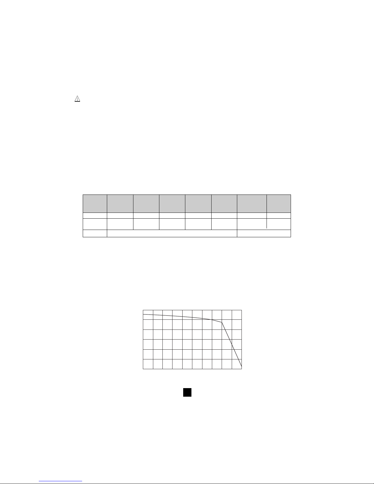
Si la tension extérieure présente aux bornes de l'appareil est supérieure aux seuils du tableau cidessous, un appui sur la touche jaune START ne déclenche pas de mesure d’isolement mais provoque
l’émission d’un signal sonore discontinu (bip, bip, bip, ...) et le clignotement du symbôle ! pendant 2
secondes, puis l'appareil repasse en mesure de tension automatique.
Si la tension extérieure présente aux bornes de l'appareil est inférieure aux seuils ci-dessous, la
mesure d'isolement est autorisée :
Essais Tension max autorisée
sous avant la mesure
50 V 8 V
100 V 16 V
250 V 50 V
500 V 50 V
1000 V 50 V
Un appui sur la touche START déclenche immédiatement la mesure. La valeur de mesure est affichée
sur l'afficheur numérique principal et sur le bargraph. Un bip sonore est émis toutes les 10 secondes
pour signaler qu'une mesure est en cours.
Si la tension générée est susceptible d'être dangereuse (> 120 V), le symbôle
s'affiche.
Si, pendant les mesures d'isolement, une tension externe > 25 VAC ±3 V ou 35VDC est détectée,
la mesure s’arrête tant que la tension est appliquée à l’instrument. Le symbole
!
clignote et
la valeur de la tension est indiquée dans le petit affichage numérique.
Si les mesures sont instables, il est possible d'utiliser la fonction SMOOTH (voir § 4.5).
L'appui sur la touche V-TIME durant la mesure permet d'afficher alternativement sur le petit afficheur,
la durée de la mesure et la tension exacte générée (voir § 4.2).
L'arrêt de la mesure est provoqué par un appui sur la touche STOP.
Après l’arrêt de la mesure, le résultat principal reste affiché.
Il est possible de faire défiler tous les autres résultats disponibles sur l’afficheur principal avec la touche
R-DAR-PI. Cette touche peut aussi être utilisée avant le déclenchement de la mesure (voir § 4.3).
Si le mode "Essai à durée programmée"
a été choisi, la touche R (t) permet d'accéder à toutes les
mesures intermédiaires mémorisées automatiquement (voir § 4.2 et 4.3).
!!!
Page 10

10
Si la fonction ALARM est activée, un buzzer se déclenchera dès que la mesure franchira le seuil
programmé dans le menu de configuration SET-UP (voir § 4.4).
■■
■■
■ Affichage des valeurs après une mesure
Les indications ci-dessous peuvent être affichées :
Touche R-DAR-PI Touche V-TIME
Afficheur Petit Petit afficheur
principal afficheur si la touche MR est activée (C.A 6543)
Résistance durée (min. sec) date, heure, tension d'essai, OBJ : TEST
DAR durée (min. sec) date, heure, tension d'essai, OBJ : TEST
PI durée (min. sec) date, heure, tension d'essai, OBJ : TEST
Capacité*
R(t) durée (min. sec) dernière tension
* La mesure de capacité (µF) ne s'affiche qu'après l'arrêt de la mesure et la décharge du circuit
3.3 Continuité (40
ΩΩ
ΩΩ
Ω
) / résistance (400 k
ΩΩ
ΩΩ
Ω)
La mesure de continuité s'effectue sur la position 40 Ω (avec un courant d'essai > 200 mA jusqu'à 20 Ω),
la mesure de résistance sur la position 400 kΩ (avec un courant d'essai < 6 mA).
■■
■■
■ Dès la rotation du commutateur vers une de ces 2 positions, l’afficheur principal indique - - - -
ΩΩ
ΩΩ
Ω
(en continuité) ou en - - - - k
Ω Ω
Ω Ω
Ω (en résistance) et le petit afficheur indique la tension présente sur les
bornes + et -.
!
Si la tension est > 3 V AC/DC et que l'on appuie sur la touche START, le symbole ! clignote et
l’alarme sonore émet des bip de refus (pendant 2 s), puis l’appareil reprend la mesure normale de
la tension.
!
Si la tension est < 3 VAC et que l'on appuie sur la touche START, la mesure se déclenche.
■■
■■
■ L’afficheur principal indique la valeur de continuité ou de résistance en cours et le petit afficheur
indique la tension présente sur les bornes + et -.
!
Les boutons R-DAR-PI, V-TIME et SMOOTH n’ont aucune action dans ces fonctions.
Il n’y a pas changement de polarité automatique en mesure de continuité.
Si, pendant les mesures de continuité ou de résistance, une tension externe > 25 VAC ±3 V ou
35VDC est détectée, la mesure s’arrête tant que la tension est appliquée à l’instrument. Le symbole
!
clignote et la valeur de la tension est indiquée sur le petit afficheur numérique.
Si la fonction ALARM est activée, un buzzer se déclenchera dès que la mesure franchira le seuil
programmé dans le menu de configuration SET-UP.
!
Page 11

11
4. FONCTIONS SPÉCIALES
4.1 Touche
2nd
Cette touche permet de sélectionner la fonction seconde des touches de fonction. Elle est toujours
associée au symbole
2nd
.
Ce symbole disparait dès l'appui sur la touche de fonction choisie, sauf si la touche ▼ est activée.
Dans ce cas, il disparaît uniquement lors d'un nouvel appui sur la touche
2nd
ou sur d’autres touches de
fonction. Cela permet de décrémenter rapidement les paramètres avec la touche ▼, sans avoir à appuyer
à chaque fois sur la touche
2nd
.
4.2 Touche V-TIME /
■■
■■
■ Fonction première V-TIME
Cette touche permet d’afficher toutes les informations secondaires disponibles, sur le petit afficheur.
Dans la fonction mesure d’isolement :
- Temps écoulé depuis le début de la mesure
- Tension entre les bornes + et - de l'appareil
- Date, heure, tension d'essai et numéro OBJ :TEST en mode rappel mémoire (MR)
Dans la fonction mesure de résistance ou de continuité :
- Tension entre les bornes + et - de l'appareil
- Date, heure, tension d'essai et numéro OBJ :TEST en mode rappel mémoire (MR)
■■
■■
■ Fonction seconde
(Essai à durée programmée)
- Le petit afficheur indique la durée de la mesure programmée dans le SET-UP, le symbole
est
allumé. Un appui sur la touche START démarre la mesure.
- La durée par défaut de la mesure est de 15 minutes (programmation en usine).
- Dès que la mesure est démarrée, le petit afficheur décrémente la durée restante.
Dès que cette durée est à zéro, la mesure s'arrête.
Pendant le déroulement d'un essai à durée programmée, des échantillons intermédiaires (valeurs de
résistance/tension en fonction du temps) sont automatiquement mémorisés.
Le temps entre chaque échantillon est de 30 s par défaut, mais cette valeur peut être changée dans le
menu SET-UP.
Les échantillons sont visualisables avec la fonction R (t) (voir § 4.3) tant qu'une nouvelle mesure n'a
pas été lancée. Ils sont effacés à chaque nouvelle mesure.
Ils sont automatiquement mémorisés avec la valeur finale de la résistance en cas d'utilisation de la
fonction MEM (mémorisation).
Si la position du commutateur rotatif est modifiée, ou si l'on appuie sur la touche STOP durant la
mesure, la mesure est interrompue.
Cette fonction est uniquement active en mesure d’isolement.
4.3 Touche R-DAR-PI / R (t)
■■
■■
■ Fonction première R-DAR-PI
La touche R-DAR-PI permet de mesurer de façon automatique l'Index de Polarisation (PI) et le Ratio
d'Absorption Diélectrique (DAR).
Ces deux paramètres sont particulièrement intéressants pour surveiller le vieillissement de l'isolement
des machines tournantes ou des câbles de grandes longueurs par exemple.
!
Page 12

12
Sur ce genre d'éléments, la mesure est perturbée au départ par des courants parasites (courant de
charge capacitive, courant d'absorption diélectrique) qui s'annulent progressivement. Pour mesurer
de manière exacte le courant de fuite représentatif de l'isolement, il est donc nécessaire d'effectuer
des mesures de longue durée, pour s'affranchir des courants parasites présents au début de la mesure.
On calcule ensuite des ratios comme le PI ou le DAR :
PI = R 10 min / R 1 min (2 valeurs à relever pendant une mesure de 10 min.)
DAR = R 1 min / R 30 s (2 valeurs à relever pendant une mesure de 1 min.)
La qualité de l'isolement est fonction des résultats trouvés.
DAR PI Etat de l'isolement
< 1,25
< 1
Insuffisant voire
< 2
dangereux
< 1,6 < 4 Bon
> 1,6 > 4 Excellent
■■
■■
■ Utilisation de la fonction R-DAR-PI
Pendant ou après une mesure, la touche R-DAR-PI permet le défilement des valeurs :
- DAR (si mesure > 1 min)
- PI (si mesure > 10 min)
- Capacité en µF (seulement après l'arrêt de la mesure et la décharge du cicuit)
- Résistance d'isolement en MΩ ou GΩ ou TΩ
Mesures de DAR ou PI automatiques :
Si la touche R-DAR-PI est actionnée durant la mesure de tension avant le lancement d'une mesure,
l'affichage est le suivant :
- - - - MΩ → DAR - - - - → PI - - - -
↑
Suivant le choix (DAR ou PI), voici le déroulement de mesure :
a) DAR : appui sur START → le symbôle DAR clignote et l'afficheur indique "
- - - -
" tant que le
calcul du cœfficient est impossible (t < 1 mn).
Par exemple : DAR
- - - -
Au bout de 1 min la mesure s'arrête et l'afficheur principal affiche automatiquement la valeur du
DAR.
La touche R-DAR-PI est utilisable pendant et après la mesure pour voir la mesure d'isolement
effectuée, mais elle ne fournit pas la valeur du PI, car la mesure n'a pas duré assez longtemps.
b) PI : appui sur START → le symbôle PI clignote et l'afficheur indique "
- - - -
" tant que le calcul du
cœfficient est impossible (t < 10 mn).
Par exemple : PI
- - - -
Au bout de 10 min, la mesure s'arrête et l'afficheur principal indique automatiquement la valeur
du PI.
Pendant et après la mesure, la touche R-DAR-PI permet d'afficher le DAR (après 1 min), le PI
(après 10 mn) et la mesure d'isolement.
Page 13

13
Remarque : Si pendant les mesures de DAR ou PI, automatiques ou non, une tension parasite
externe importante apparaît, ou que la résistance d'isolement sort des gammes de mesure de
l'appareil, les mesures de DAR ou PI sont interrompues et l'écran indique :
DAR MΩ
ou
PI MΩ
Remarque : Les temps de 10 min / 1 min pour le calcul du PI sont modifiables dans le menu
SET-UP (voir § 4.7) pour s'adapter à une éventuelle évolution normative ou à une application
particulière.
■■
■■
■ Fonction seconde R (t)
La touche R(t) permet d'accéder aux valeurs de résistances intermédiaires d'isolement mesurées en
fonction du temps, après une mesure en mode "Essai à durée programmée"
(voir § 4.2).
Le temps entre chaque échantillon mémorisé est programmé dans le menu de configuration SET-UP.
Cette fonction est également disponible sur le modèle C.A 6541 qui ne comporte ni mémoire vive pour la
mémorisation des données mesurées, ni interface pour récupérer ces données de l’instrument sur un PC.
Sur le C.A 6541, pendant la mesure
, jusqu’à 20 échantillons peuvent être enregistrés dans l’appareil
à la fréquence "d’échantillonnage" choisie dans le SET-UP (la valeur par défaut étant 30 secondes).
Il est possible de mémoriser plus de 20 échantillons si la mémoire processeur disponible le permet.
Sur le C.A 6543, le nombre d'échantillons pouvant être mémorisés n'est limité que par la mémoire vive
disponible.
Après un appui sur la touche R(t), l’instrument passe en mode visualisation:
- le petit afficheur indique le temps 00:30 (si la fréquence d’échantillonnage est de 30 s)
- l’afficheur principal indique la valeur R correspondante.
La touche V-TIME permet d’alterner entre temps et tension (sur le petit afficheur), en association avec
la valeur R à l’afficheur principal.
La touche
▲
▼
, permet de faire défiler tous les échantillons mémorisés lors de la mesure. Il est ainsi
possible de relever les éléments pour réaliser un diagramme R(t) et U(t).
Il est donc possible de réaliser sur site, une analyse R(t), en l'absence d'une imprimante ou d'un PC.
Un nouvel appui sur la touche R(t) ou R-DAR-PI, permet de sortir de cette fonction.
4.4 Touche
✻✻
✻✻
✻ / ALARM
■■
■■
■ Fonction première ✻
Cette fonction permet d'allumer ou d'éteindre le rétro-éclairage.
■■
■■
■ Fonction seconde ALARM
Activation/désactivation de la fonction ALARM. Le symbôle correspondant s'affiche en cas d'activation.
Si cette fonction est active et que la valeur limite haute ou basse programmée dans le menu SET-UP est
dépassée pendant la mesure, le symbole ALARM clignotera et le buzzer (s’il est activé) retentira en
permanence.
Il est possible de programmer une limite différente dans chaque fonction, les limites seront gardées en
mémoire après l'arrêt de l'appareil.
Page 14

14
4.5 Touche ▼ / SMOOTH
■■
■■
■ Fonction première
▼
Permet de sélectionner un paramètre à modifier - le paramètre actif clignote.
Il est modifiable avec la touche
▲
▼
(voir § 4.6).
■■
■■
■ Fonction seconde SMOOTH
Permet d’activer un filtre numérique pour les mesures d'isolement. Il affecte uniquement l'affichage (qui
est lissé) et non les mesures.
Cette fonction est utile en cas de forte instabilité des valeurs d'isolement affichées, due à une forte
composante capacitive de l'élément à tester par exemple.
4.6 Touche
▲
▼
Cette fonction permet de modifier les paramètres clignotants affichés, ou de consulter les valeurs R (t)
(voir § 4.3).
En règle générale, deux chiffres (jour, mois, heure , min., sec., OBJ, TEST) clignotent.
Les fonctions
▲▲
▲▲
▲ et
▼▼
▼▼
▼ disposent d'un mode "rouleau" : dès que la limite haute ou basse de modification
est atteinte, le paramètre à modifier bascule automatiquement sur la limite basse ou haute suivante.
■■
■■
■ Fonction première
▲▲
▲▲
▲ : Un appui court permet d'incrémenter d'une unité le nombre affiché.
En cas d'appui long sur cette touche, l'incrémentation se fera à vitesse rapide.
■■
■■
■ Fonction seconde
▼▼
▼▼
▼ : Un appui court permet de décrémenter d'une unité le nombre affiché.
En cas d'appui long, la décrémentation se fera à vitesse rapide.
Contrairement à toutes les fonctions secondes des autres touches, il n'est pas nécessaire ici d'appuyer
à chaque fois sur la touche
2nd
pour accéder à la fonction ▼. Le symbôle
2nd
reste en effet affiché
et donc valide pour la fonction ▼ (seulement) tant que l'utilisateur ne le désactive pas par un nouvel
appui sur la touche
2nd
ou sur une autre touche.
4.7 Fonction SET-UP (configuration de l'appareil)
Cette fonction, située sur le commutateur rotatif, permet de changer la configuration de l'appareil en
accédant directement aux paramètres à modifier.
Après avoir tourné le commutateur rotatif sur la position SET-UP :
- tous les segments de l'afficheur sont activés pendant 1 seconde,
- le numéro de la version logicielle s'affiche
- le numéro de série de l'appareil s'affiche
- PUSH apparaît alors sur le petit afficheur et btn sur l'afficheur principal, pour solliciter l'appui d'une
touche.
La fonction SET-UP permet alors d’accéder directement aux paramètres à modifier, en appuyant
sur la touche correspondante :
- Après avoir appuyé sur une touche, les chiffres ou les symboles correspondant à la fonction sélectionnée
apparaissent sur l’écran.
- Les chiffres ou les symboles pouvant être modifiés clignoteront. La procédure normale de modification
avec les touches
▼
et
▲
▼
doit être utilisée.
- Tous les paramètres sont enregistrés immédiatement et en permanence.
Le tableau de la page suivante définit les touches actives dans la fonction SET-UP et l'affichage
correspondant, avec les plages de réglage possible.
Page 15

15
Paramètres Touche Affichage
à modifier de commande principal petit symboles valeurs
Durée du test, en mode
15 : 00 min. sec, 1 - 59 min
"Essai à durée programmée"
1er et 2e temps pour R-DAR-PI second temps premier temps min : sec
00 : 59
le calcul du PI (10 min) (1 min)
Durée entre les
échantillons en mode
R (t) 00 : 30 min : sec 5 s - 10 min
"Essai à durée programmée"
Limite pour MΩ-50 V ALARM 50 kΩ 50 V ALARM < 2 k-200 G et ><
Limite pour MΩ-100 V ALARM (2è appui) 100 kΩ 100 V ALARM < 4 k-400 G et ><
Limite pour MΩ-250 V ALARM (3è appui) 250 kΩ 250 V ALARM < 10 k-1 T et ><
Limite pour MΩ-500 V ALARM (4è appui) 500 kΩ 500 V ALARM < 20 k-2 T et ><
Limite pour MΩ-1000 V ALARM (5è appui) 1000 kΩ 1000 V ALARM < 40 k-4 T et ><
Limite pour 400 kΩ
ALARM (6è appui) 100 kΩ rES ALARM <
0,01-400 kΩ
(mesure de résistance) et ><
Limite pour 40 Ω
ALARM (7è appui) 2 Ω Cont ALARM < 0,01-40 Ω et ><
(mesure de continuité)
Heure V-TIME 12 :55
hh(0-23)
mn (0-59)
Date (version europe) V-TIME (2è appui) 17.03 1999 jj.mm .aaaa
Version : USA, Europe V-TIME (3è appui) USA/Euro USA/Euro
Effacement mémoire MEM puis MEM (2 s) cLr ALL MEM
Effacement sélectif MEM puis
▼
et
▲
▼
cLr
Numéro MEM +
00...99
de la mémoire et MEM (2 s) d'OBJ : TEST OBJ : TEST
300...9600
Baud PRINT 9600 bAUd
ou "parallel"
Buzzer
✻
On
On / OFF
Arrêt automatique
✻
(2è appui) On On / OFF
Compensation
✻
(3è appui) - - - -
On
W
0
On / OFF
puis ▲ et START (valeur si START) et 0,01-5 Ω
Configuration par défaut
✻
(4
ème
appui)
DFLt SEt
puis START
Verrouillage test isolement
✻
(5
è
appui) On 50 V On / OFF
Verrouillage test isolement
✻
(6è appui) On 100 V On / OFF
Verrouillage test isolement
✻
(7è appui) On 250 V On / OFF
Verrouillage test isolement
✻
(8è appui) On 500 V On / OFF
Verrouillage test isolement
✻
(9è appui) On 1000 V On / OFF
Les valeurs indiquées dans ce tableau, dans les colonnes "Affichage / principal" et "Affichage / petit
sont les valeurs par défaut programmées en usine. En cas de modification par erreur, il est possible de
les retrouver : voir § 4.7.4.
Page 16

16
4.7.1 Effacement de la mémoire
Dans le SET-UP, appuyer sur la touche MEM :
- Le symbole MEM clignote
- Le petit afficheur indique ALL
- L'afficheur principal indique cLR
Pour effacer toute la mémoire, appuyer de nouveau sur la touche MEM pendant 2 secondes :
- Le symbole MEM s’affiche de manière stable.
- L’afficheur principal indique FrEE
Pour effacer le contenu d'un numéro OBJ : TEST particulier :
- Sélectionner le numéro à l’aide des touches
▼
et
▲
▼
- cLr reste affiché sur l'afficheur principal
Appuyer de nouveau sur la touche MEM pendant 2 secondes pour effacer :
- Le numéro OBJ : TEST est indiqué sur le petit afficheur
- L’afficheur principal indique FrEE
4.7.2 Débit en bauds (RS 232)
Dans le SET-UP, appuyer sur la touche PRINT.
L’afficheur principal indique le débit en bauds, soit 300, 600, 1200, 2400, 4800, 9600 ou Parallel.
Sur le petit afficheur, baud apparaît. La valeur peut être modifiée à l’aide des touches
▲▲
▲▲
▲ et
▼▼
▼▼
▼.
L'affichage "Parallel" signifie que le mode parallèle est sélectionné, pour imprimer sur des imprimantes
parallèles via l'adaptateur série-parallèle (RS 232-Centronics).
4.7.3 Compensation de la résistance des fils
Dans le SET-UP, troisième appui sur la touche ✻ :
Le symbole
W
0
apparaît et le petit afficheur indique On. Il est possible de le mettre sur OFF avec la
touche
▲
▼
. Dans ce cas, la résistance des cordons ne sera pas soustraite des mesures de continuité.
Pour mémoriser la résistance des cordons :
- Les relier ensemble et appuyer sur START (dans le SET-UP, position
W
0
)
- La résistance des cordons sera mémorisée et indiquée sur l’afficheur principal
Remarques :
- Cette valeur est conservée en mémoire, même lorsque l’instrument est hors tension.
- Cette compensation n’est active que dans la mesure de continuité.
- Pour activer/désactiver cette fonction, il suffit de sélectionner On ou OFF sur le petit afficheur avec
la touche
▲
▼
.
- La valeur mémorisée sera conservée et affichée sur l’afficheur principal, mais pourra être active ou
non, en fonction de l’état du petit afficheur.
- Des valeurs entre 0 et 5 Ω peuvent être mémorisées pour la compensation des cordons. Au delà rien
n'est mémorisé.
4.7.4 Configuration par défaut de l'appareil
Dans le SET-UP, quatrième appui sur la touche ✻ :
- Le petit afficheur indique SEt (clignotant).
- L’afficheur principal indique DFLt
Appuyer sur START pour reconfigurer l'appareil avec les paramètres par défaut (voir tableau précédent).
Page 17

17
4.7.5 Verrouillage des mesures d'isolement
Cette fonction interdit l’utilisation de la mesure de l'isolement sous certaines tensions d'essai. Cela
permettra de confier l'appareil à des personnes moins averties, pour des applications particulières par
exemple (téléphonie...).
Dans le SET-UP, à partir du 5è appui sur ✻ :
- Les tensions d’essai apparaissent successivement avec la touche ✻ sur le petit afficheur et On ou
OFF sur l’afficheur principal.
- Choisir On ou OFF à l’aide de la touche
▲
▼
pour chaque tension d'essai, pour verrouiller (OFF) ou
déverrouiller (On) les essais d'isolement sous ces tensions.
5. UTILISATION
5.1 Déroulement des mesures
■ Mettre l'appareil en marche en positionnant le commutateur sur la position correspondante (MΩ,
40 Ω
ou 400 kΩ). Tous les segments de l'écran LCD s'affichent, puis la tension des piles ou de
la batterie.
■ Raccorder les cordons des bornes + et - aux points de mesure.
■ La tension d'entrée est mesurée en permanence et affichée sur le petit afficheur.
Si une tension externe supérieure aux seuils décrits dans les § 5.2, 5.3 et 5.4, est présente, la
mesure sera interdite.
■ Un appui sur START/STOP permet de déclencher la mesure.
■ Un nouvel appui sur START/STOP permet d'arrêter la mesure. Le dernier résultat reste affiché
jusqu'à la prochaine mesure ou la rotation du commutateur.
Si une tension > 25 VAC ou 35 VDC survient pendant toutes les mesures, l'appareil indiquera cette
tension sur le petit afficheur avec le symbôle d’avertissement clignotant et arrêtera la mesure en cours.
Nota : Un certain nombre de fonctions spéciales sont utilisables (voir § 4).
5.2 Mesure d'isolement (voir § 3.2)
Dans cette fonction, l'appareil peut mesurer des isolements de 2 kΩ à 4 TΩ, en fonction de la tension
d'essai choisie, parmi 50 - 100 - 250 - 500 et 1000 V.
■ Positionner le commutateur sur MΩ-50 V, ou MΩ-100 V, ou MΩ-250 V, ou MΩ-500 V, ou MΩ-1000 V
■ Relier l'appareil à l'élément à tester. Si la tension présente est supérieure à 8 V sous M
ΩΩ
ΩΩ
Ω-50 V,
ou 16 V sous M
ΩΩ
ΩΩ
Ω-100 V, ou 50 V sous les autres tensions, la mesure sera interdite.
■ Lancer la mesure et relever les résultats.
Il est possible de faire défiler tous les résultats sur l’afficheur principal avec la touche R-DAR-PI (voir
§ 4.3) ou sur le petit afficheur avec la touche V-TIME (voir § 4.2).
R (t) permet d'accéder aux valeurs intermédiaires mesurées et mémorisées à la cadence réglée dans
le SET-UP, en mode "Essai à durée programmée". Ces échantillons sont disponibles jusqu'au lancement
d'une autre mesure ou jusqu'à la prochaine rotation du commutateur (voir § 4.3)
Pour la mesure de forts isolements (> 1 G
ΩΩ
ΩΩ
Ω), il est conseillé d'utiliser la borne de garde " G " pour
supprimer l'influence des courants de fuite superficiels. La garde sera connectée sur une surface susceptible
d'être le siège de circulation des courants superficiels au travers de poussière et d'humidité : par exemple,
surface isolante d'un câble ou d'un transformateur, entre deux points de mesure. L'utilisation d'une pince
crocodile est dans ce cas préférable à celle d'une pointe de touche, tenue à la main afin d'éviter des effets
de fuite ou des effets capacitifs (voir § 11).
Dès l'arrêt des mesures d'isolement, le circuit testé est automatiquement déchargé au travers
d'une résistance interne à l'appareil.
Page 18

18
5.3 Mesure de la continuité (voir § 3.3)
Dans cette fonction, le courant de mesure est > 200 mA de 0 à 20 Ω et > 140 mA de 20 à 40 Ω.
Cette mesure sert, par exemple, à tester la faible résistance des câbles de masse PE.
Les calibres de mesure s'incrémentent automatiquement jusqu’à 40 Ω avec une résolution maximale
de 0,01 Ω.
■ Positionner le commutateur sur la position 40 Ω
■ Relier l'appareil à l'élément à tester
■ Si la tension présente est > 3 V, la mesure sera interdite
■ Lancer la mesure et relever les résultats.
NOTA : Il est possible de compenser la résistance des cordons de mesure (voir § 4.7.3)
Les boutons R-DAR-PI et V-TIME n’ont aucune action dans cette fonction.
Il n’y a pas de changement de polarité automatique dans la mesure de continuité.
5.4 Mesure de résistance (voir § 3.3)
Dans cette fonction, le courant de mesure est limité à 6 mA. Les calibres de mesure s'incrémentent
automatiquement jusqu’à 400 kΩ avec une résolution maximale de 0,01 Ω.
■ Positionner le commutateur sur la position 400 kΩ
■ Relier l'appareil à l'élément à tester
■ Si la tension présente est > 3 V, la mesure sera interdite
■ Lancer la mesure et relever les résultats.
Pendant la mesure, la chute de tension sur l’entrée est indiquée sur le petit afficheur (intéressant pour
la mesure d'éléments à jonctions multiples : thyristors, diodes haute tension...).
La tension à vide est égale à l’alimentation pile (C.A 6541) ou batterie rechargeable (C.A 6543).
NOTA : Les touches R-DAR-PI et V-TIME n’ont aucune action dans cette fonction.
5.5 Mesure de capacité
La mesure de capacité s'effectue automatiquement lors de la mesure d'isolement, et s'affiche après
l'arrêt de la mesure et la décharge du circuit, grâce à la touche R-DAR-PI.
!
!
Page 19
19
6. MEMOIRE / RS 232 (C.A 6543)
6.1 Caractéristiques de la RS 232
■ La vitesse en bauds peut être réglée sur 300, 600, 1200, 2400, 4800, 9600, ou "Parallel" pour
l'impression sur des imprimantes parallèles via l'adaptateur série/parallèle en option.
Ce réglage s'effectue dans le menu SET-UP (voir § 4.7)
■ Format des données : 8 bits de données, 1 bit d'arrêt, sans parité, protocole Xon / Xoff
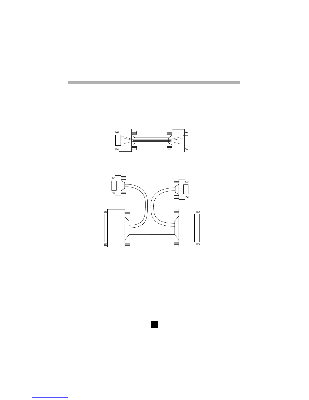
■ Connexion à l’imprimante série
Connecteur9brochesfemelle
versC.A6543
Connecteur9brochesmâle
versl'imprimantesérie
2
2
3
3
5
5
vuedeface
vuedeface
■ Connexion à un PC ou à une imprimante parallèle
Connecteur 9 broches femelle vers PC
➂
➁
Connecteur 25 broches
femelle vers le PC ou
adaptateur série-parallèle
➀
Connecteur 25 broches
Connecteur 9 broches femelle
vers C.A 6543
Liaisons nécessaires DB9
➔➔
➔➔
➔ B25 (
➀➀
➀➀
➀
→→
→→
→
➁➁
➁➁
➁)
■■
■■
■ Conversion DB25
➔➔
➔➔
➔ DB9 (
➁➁
➁➁
➁
→→
→→
→
➂➂
➂➂
➂) :
(câble null - modem standard) :
1 ➔ 8 6 ➔ 20 2 ➔ 3
2 ➔ 2 7 ➔ 5 3 ➔ 2
3 ➔ 3 8 ➔ 4 7 ➔ 5
4 ➔ 6 9 ➔ 22
5 ➔ 7
6.2 Enregistrement / relecture des valeurs mémorisées ( Touche MEM/MR )
6.2.1 Fonction première MEM (mémorisation)
Cette fonction permet d'enregistrer des résultats dans la mémoire vive de l'appareil.
Ces résultats sont mémorisables à des adresses repérées par un numéro d'objet (OBJ) et un numéro
de test (TEST).
Page 20

20
Un objet représente une "boîte" dans laquelle on peut ranger 99 tests. Un objet peut ainsi représenter
une machine ou une installation sur laquelle on va effectuer un certain nombre de mesures, quelles
qu'en soient la nature (isolement, résistance, continuité).
1. Quand la touche est activée, le symbôle MEM clignote et le petit afficheur indique le premier numéro
OBJ : TEST libre, par exemple, 02 : 01. L'afficheur principal indique FrEE (libre).
Le numéro OBJ est celui de la dernière mesure mémorisée, mais le numéro TEST est incrémenté de 1.
Il est toujours possible de modifier OBJ : TEST avec les touches
▼
et
▲
▼
.
Si l’utilisateur sélectionne une adresse de mémoire déjà occupée, OCC apparaît sur l’afficheur principal.
Si un nouvel OBJ est sélectionné, TEST est mis sur 01.
2. En appuyant de nouveau sur la touche MEM, les résultats de mesure en cours seront enregistrés
dans l’adresse mémoire sélectionnée (qu’elle soit ou non occupée). Le symbôle MEM ne clignote
plus et reste affiché. L’heure et la date de cet enregistrement sont mémorisées avec les données déjà
disponibles (R, U, t).
Si une autre touche que MEM ou le commutateur est activé avant le deuxième appui sur MEM,
on sort du mode enregistrement sans avoir mémorisé les résultats.
3. Si un essai à durée programmée a été réalisé, des mesures intermédiaires (échantillons) sont
disponibles (voir § 4.3). Elles sont automatiquement enregistrées sous le même numéro OBJ : TEST
que la mesure finale.
■■
■■
■ Estimation de la capacité d'enregistrement des résultats
Espace mémoire total : 128 k.octets
Gestion interne : 8 k.octets
Espace mémoire disponible :120 k.octets
Un résultat de mesure d'isolement nécessite environ 80 octets.
En "Essai à durée programmée"
, un échantillon nécessite 10 octets de plus.
Une mesure de la résistance ou de la continuité nécessite 26 octets.
Il est donc possible d’enregistrer environ 1500 mesures d’isolement ou environ 4000 tests de résistance
ou de continuité.
■■
■■
■ Espace mémoire disponible
Cette fonction s'active automatiquement lors de l’enregistrement d’un résultat.
Appuyer une fois sur MEM pour obtenir le numéro OBJ. TEST libre suivant; l'indication du bargraph est
proportionnelle à la mémoire libre disponible.
- Si toute la mémoire est libre, tous les segments sont activés.
- Si toute la mémoire est pleine, la flèche de gauche du bargraph clignote.
- Dès que l’enregistrement est terminé, le bargraph disparaît.
Un segment du bargraph équivaut à environ 50 enregistrements.
6.2.2 Fonction seconde MR
La fonction MR permet de rappeler n’importe quelle donnée de la mémoire, quelle que soit la position du
commutateur rotatif.
■ Quand la touche est activée, le symbole MR s’affiche (sans clignoter).
Le petit afficheur indique le dernier numéro OBJ : TEST occupé, par exemple, 02 :11.
02 "11" en regard du symbole TEST clignote, la procédure de modification normale avec les touches
▼
et
▲
▼
doit être utilisée pour sélectionner le numéro OBJ : TEST désiré.
Page 21

21
Si un nouvel OBJ est sélectionné, TEST est automatiquement réglé sur le numéro maximum mémorisé.
A ce niveau il est possible de consulter toute la mémoire de résultat avec les touches
▼
et
▲
▼
car les
valeurs de mesure correspondant au numéro OBJ : TEST sélectionné s'affichent sur l'afficheur
principal. Il est possible de les faire défiler avec la touche R-DAR-PI.
■ La touche V-TIME est active et donne accès à date / heure / U / numéro OBJ-TEST pour chaque
résultat.
Si l'enregistrement sélectionné par le numéro OBJ : TEST correspond à un essai à durée programmée
, on peut accéder aux valeurs R (t) en appuyant sur la touche R (t). Le petit afficheur change et
indique min : sec (temps du 1er échantillon) et le symbole
clignote sur l'écran. Vous pouvez faire
défiler les autres échantillons avec la touche
▲
▼
.
Pour sortir du mode R (t) et revenir à l'état rappel de mémoire normal (OBJ : TEST), appuyer
de nouveau sur les touches R (t) ou R-DAR-PI.
!
Pour sortir de la fonction MR, appuyer de nouveau sur MR ou tourner le commutateur.
Page 22

22
6.3 Impression des valeurs mesurées (touche PRINT/PRINT MEM) (C.A 6543)
Si vous utilisez une imprimante série, choisissez la vitesse de communication appropriée, dans le menu
SET-UP, entre 300...9600 bauds, puis programmer l'imprimante au format géré par l'instrument (voir § 6.1).
Si vous utilisez une imprimante parallèle, vous devez régler la vitesse sur "Parallel" dans le SET-UP et
utiliser l'adaptateur série/parallèle vendu en option (brancher en série le câble livré + adaptateur + câble
Centronics de l'imprimante).
Deux modes d'impression sont disponibles :
- Impression immédiate de la mesure (PRINT)
- Impression des données mémorisées (PRINT memory)
Si la transmission de données vers l'imprimante se passe bien, le symbole COM clignotera sur l'afficheur.
Si un problème survient, le symbole COM reste affiché en permanence sur l'écran LCD.
6.3.1 Impression immédiate de la mesure (touche PRINT)
A la suite d'une mesure ou après l'accès au mode MR (Rappel Mémoire), la fonction PRINT permet
l’impression des résultats de mesure.
Dès l'activation de la touche, elle imprime :
- 1 groupe de mesures (U/R/DAR/PI/date/heure) en cas de test normal,
- les valeurs R(t) si la fonction "Essai à durée programmée"
a été activée.
Pour arrêter l’impression, changez la position du commutateur rotatif.
Suivant la fonction utilisée on obtient les modèles suivants.
■■
■■
■ Mesure d'isolement
CHAUVIN ARNOUX C.A 6543
Numéro de l’instrument : 000 001
TEST DE RESISTANCE D'ISOLEMENT
OBJET : 01 TEST : 01 (imprimé uniquement en mode MR)
Description : ................................................
.....................................................................
Date : ......................................... 31.03.1998
Heure de début : ................................14h55
Durée d’exécution :.............. 15 min. 30 sec
Température : .............................°C .........°F
Humidité relative : ..................................... %
Tension d’essai : ...............................1000 V
Résistance d'isolement (R) : ..... 385 GOhm
DAR (R 1'/R 30") :............................... 1,234
PI (R 10'/R 1") : ................................... 2,345
Commentaires : ...........................................
.....................................................................
Date du prochain test : .................. /..../.......
Après un "Essai à durée Programmée" d'autres résultats s'impriment (échantillons intermédiaires) :
Temps Résistance Tension
00 : 30 35,94 GOhm 1005 V
01 : 00 42,00 GOhm 1005 V
01 : 30 43,50 GOhm 1005 V
etc... Une ligne pour la signature de l'opérateur apparaît à
la fin de l’impression.
!
Page 23

23
■■
■■
■ Mesure de continuité ou de résistance
CHAUVIN ARNOUX C.A 6543
Numéro de l’instrument : 000 001
TEST DE CONTINUITE ou TEST DE RESISTANCE
OBJET : 01 TEST : 01 (imprimé uniquement en mode MR)
Description : ................................................
.....................................................................
Date : ......................................... 31.03.1998
Heure de début : .............................. 14 h 55
Courant d’essai : .......................... > 200 mA
Compensation des cordons : ............ 0,12 Ω
Chute de tension : ............................... 0,9 V
Continuité ou Résistance : ............... 0,45 Ω
Commentaires : ...........................................
.....................................................................
.....................................................................
Date du prochain test : ................... /..../.......
Une ligne pour la signature de l'opérateur apparaît à la fin de l’impression.
6.3.2 Impression des données mémorisées (touche PRINT MEM)
Cette fonction permet l'impression du contenu de la mémoire vive de l'appareil.
Le petit afficheur indique 01 :01 pour le numéro OBJ : TEST (adresse de départ de l'impression).
L’afficheur principal indique le dernier enregistrement en mémoire (adresse de fin de l'impression).
Par exemple 12 : 06;
01 en regard de la position OBJ clignote et la procédure de modification normale doit être utilisée
(touches
▼
et
▲
▼
) pour définir les adresses début/fin de l'impression.
Pour quittez sans imprimer, changer la position du commutateur rotatif.
Pour lancer l’impression, appuyez de nouveau sur la touche PRINT.
Pour arrêter l’impression, changer la position du commutateur rotatif.
L’impression de chaque groupe de données est réduite aux résultats principaux.
Exemple :
CHAUVIN ARNOUX C.A 6543
Numéro de l’instrument : 000 001
TEST DE CONTINUITE
OBJET : 01 TEST : 01
Date : ........................................ 31.03.1998
Heure de début : ............................... 14h 55
Continuité : ....................................... 0,45 Ω
TEST DE CONTINUITE
OBJET : 01 TEST : 02
Date : ........................................ 31.03.1998
Heure de début : ................................ 15h00
Continuité : ........................................ 0,91 Ω
Page 24
24
TEST DE RESISTANCE D'ISOLEMENT
OBJET : 01 TEST : 03
Date : ........................................ 31.03.1998
Heure de début : ............................... 15h 10
Durée d’exécution : .............. 15 min 30 sec
Température : ............................ °C .........°F
Humidité relative :..................................... %
Tension d’essai : ............................... 1000 V
Résistance de l’isolement (RI) : ..... 385 GΩ
DAR (RI 1’/30“) : ................................. 1,234
PI (RI 10’/RI1’) : .................................. 2,345
Commentaires : ...........................................
.....................................................................
.....................................................................
Une ligne pour la signature de l'opérateur apparaît à la fin de l’impression.
6.4 Impression avec l’adaptateur série-parallèle
1. Branchez le câble RS232 null - modem au C.A 6543
2. Reliez ce câble à l’adaptateur, puis l’adaptateur au câble de l’imprimante
3. Mettez l’imprimante sous tension
4. Mettez le C.A 6543 sous tension
5. Pour lancer une impression de mesures non enregistrées (impression immédiate), appuyez sur
PRINT après une mesure
6. Pour lancer une impression de mesures enregistrées, appuyez sur la touche «PRINT MEM»
!
ATTENTION : Cet adaptateur est conçu exclusivement pour être utilisé avec le C.A 6543 et
ne convient à aucune autre application.
7. CARACTERISTIQUES
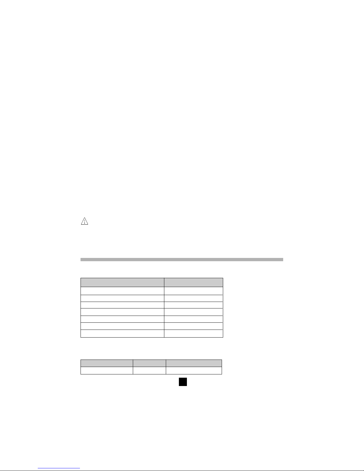
7.1 Conditions de référence
Grandeurs d’influence Valeurs de référence
Température 23°C +/- 3 K
Humidité relative 45 à 55 %
Tension d’alimentation 9 à 12 V
Plage de fréquences DC et 15,3...65 Hz
Capacité en parallèle sur la résistance 0 µF
Champ électrique nul
Champ magnétique < 40 A/m
7.2 Caractéristiques par fonction
7.2.1 Tension
Domaine de mesure Résolution Plage de fréquences
1... ... 1000 V 1 V DC / 16 ... 420 Hz
Page 25
25
■■
■■
■ Précision : ±1% L ±3 pt, tension AC sinusoïdale ou DC
■■
■■
■ Résistance d'entrée : 750 kΩ environ
Attention : Cet appareil est Cat III 600 V, selon l'EN 61010-1. Il ne doit pas être connecté à des tensions
> 600 V par rapport à la terre.
7.2.2 Résistance d’isolement
■■
■■
■ Méthode : Mesure tension-courant selon l'EN 61557-2
■■
■■
■ Tension de sortie nominale : 50, 100, 250, 500, 1000 VDC
■■
■■
■ Tension à vide : ≤ 1,1 x Un ± 5 V (50, 100, 250, 500, 1000 V)
■■
■■
■ Courant nominal : > 1 mADC à la tension nominale
■■
■■
■ Courant de court-circuit : < 6 mADC
■■
■■
■ Surtension max. : Ueff max. = 1200 V AC et DC pendant 10 secondes entre les bornes "+" et "-"
660 V AC et DC entre les bornes "G" et "-" ou "G" et "+"
■■
■■
■ Gammes de mesure :
50 V : 2 kΩ... 200 GΩ
100 V : 4 kΩ... 400 GΩ
250 V : 10 kΩ... 1 TΩ
500 V : 20 kΩ... 2 TΩ
1000 V : 40 kΩ... 4 TΩ
Plage 2 ... 999 kΩ
4,00..39,99 40,0..399,9
400...999 MΩ
4,00..39,99 40,0..399,9
400...999 GΩ
1,000..3,999
MΩ MΩ
1,000..3,999
GΩ GΩ 1,000...3,999
MΩ
GΩ TΩ
Résolution 1 kΩ 10 kΩ 100 kΩ 1 MΩ 10 MΩ 100 MΩ 1 GΩ
Tension
50, 100, 250 50, 100, 250 50, 100, 250, 50, 100, 250, 50, 100, 250, 50, 100, 250, 250 V,
500, 1000 V 500, 1000 V 500, 1000 V 500, 1000 V 500, 1000 V 500, 1000 V 500, 1000 V
Précision ±(5% L +3 pt) ±(15% L +10 pt)
Mesure de la tension DC pendant ou après l’essai d’isolement
■■
■■
■ Plage de tensions DC : 25...1000 V
■■
■■
■ Résolution : 0,5% UDC
■■
■■
■ Précision : ±1% L ±3 pt
Mesure de la capacité (suite à la décharge de l'élément testé)
■■
■■
■ Gamme : 0,005...4,999 µF
■■
■■
■ Résolution : 1 nF
■■
■■
■ Précision : ±(10% + 1 pt)
Courbes d'évolution typique des tensions d'essai en fonction de la charge
Tension d'essai 50 V
0
100
90
80
70
60
Résistance en kW
Tension de sortie (V)
50
40
30
20
10
0
10
20
30
40
50
60
!
Page 26

26
Tension d'essai 100 V
0
100
90
80
70
60
Résistance en kW
Tension de sortie (V)
50
40
30
20
10
0
20
40
60
80
100
120
Tension d'essai 250V
0
250
200
150
100
50
0
Résistance en kW
Tension de sortie (V)
50
100
150
200
250
300
Tension d'essai 500V
0
500
400
300
200
100
0
Résistance en kW
Tension de sortie (V)
100
200
300
400
500
600
Page 27

27
Gamme 1000V
0
1000
800
600
400
200
50
Résistance en kW
Tension de sortie (V)
200
400
600
800
1000
1200
■■
■■
■ Temps d'établissement typique de la mesure en fonction des éléments testés
Ces valeurs incluent les influences dues à la charge de la composante capacitive, au système de
gamme automatique et à la régulation de la tension d'alimentation.
Charge non capacitive Charge avec capacité de 1 µF
Isolement de 1 MΩ 7 s 7s
Isolement de 500 GΩ 17 s 20 s
■■
■■
■ Temps de décharge de l'élément testé (à travers une résistance interne de 750 k
ΩΩ
ΩΩ
Ω) jusqu'à 25 V
Tension initiale Temps de décharge
1000 V 2,8 s
500 V 2,2 s
250 V 1,7 s
100 V 1 s
50 V 0,5 s
■■
■■
■ Gamme des ratios DAR et PI : 0,000 à 9,999
Précision : ±5%
7.2.3 Continuité
■■
■■
■ Méthode : Mesure tension-courant selon l'EN 61557-4
■■
■■
■ Tension à vide : Max. 12,4 VDC (< 15 V avec alimentation extérieure)
■■
■■
■ Courant de court-circuit : > 200 mADC
■■
■■
■ Surtension max. : Ueff max. = 1200 V AC et DC pendant 10 secondes entre les bornes "+" et "-"
660 V AC et DC entre les bornes "G" et "-" ou "G" et "+"
■■
■■
■ Compensation des cordons d’essai :
R∆ est mesurée cordons d'essai en court-circuit dans le menu SET-UP (voir § 4.7), cette valeur est
mémorisée et soustraite de toute mesure de continuité. La compensation est limitée à 5 Ω.
R affichée = R mesurée - R∆
■■
■■
■ Plage de mesure de continuité : 0,01 à 39,99 Ω
■■
■■
■ Résolution : 0,01 Ω
Page 28

28
■■
■■
■ Courant de fonctionnement : > 200 mA de 0,01 à 20,00 Ω et > 140 mA de 20,01 à 39,99 Ω
■■
■■
■ Précision : ±3% L ±4 pt
■■
■■
■ Charge inductive max. : 5 H sans dommage pour l'instrument
■■
■■
■ Tension mode série max. : 3 VAC/DC; au-dessus de cette valeur, la mesure sera interdite
7.2.4 Résistance
■■
■■
■ Méthode : Mesure tension-courant
■■
■■
■ Tension à vide : max. 12,4 VDC (< 15 V avec alimentation extérieure)
■■
■■
■ Courant de court-circuit : < 6 mA DC
■■
■■
■ Surtension max. : Ueff max. = 1200 V AC et DC pendant 10 secondes entre les bornes "+" et "-"
660 V AC et DC entre les bornes "G" et "-" ou "G" et "+"
■■
■■
■ Tension mode série max. : 3 VAC ou 3 VDC; au-dessus de cette valeur, la mesure sera interdite.
Plage 0,01..39,99 Ω 40,0..399,9 Ω 0,400..3,999 kΩ 4,00..39,99 kΩ 40,0..399,9 kΩ
Résolution 0,01 Ω 0,1 Ω 1 Ω 10 Ω 100 Ω
Précision ±3 % L ±3pt
7.3 Alimentation
■■
■■
■ L'alimentation de l'appareil est réalisée par :
- 8 piles de 1,5 V LR 14 (C.A 6541)
- Batteries rechargeables NiMh (C.A 6543)
Recharge ext. : 85 à 256 V / 50-60 Hz (sécurité électrique : 256 V Cat. III)
Appareil C.A 6541 C.A 6543
Mesure Autonomie moyenne Autonomie moyenne
Mesure d'isolement : 21 000 mesures de 5 s et pause de 20 s 5 000 mesures de 5 s et pause de 20 s
à charge nominale * (1) à charge nominale * (2)
Mesure de continuité : 16 000 mesures de 5 s et pause de 20 s 4 000 mesures de 5 s et pause de 20 s
à charge nominale * à charge nominale *
* Charge nominale : 1000 V/1 mA
(1) Si nous supposons une mesure PI de 10 minutes, 5 fois par jour, l'autonomie sera de 67 jours (soit 10 semaines ou 2,5 mois)
(2) Si nous supposons une mesure PI de 10 minutes, 5 fois par jour, l'autonomie sera de 16 jours (soit 2,5 semaines ou 0,5 mois)
■■
■■
■ Temps de recharge (C.A 6543)
4,5 heures pour recouvrer 100% de la capacité (temps de recharge max : 6 heures)
0,5 heures pour recouvrer 10% de la capacité (autonomie : 1 jour environ)
7.4 Conditions d'environnement
■■
■■
■ Domaine d'utilisation
-10 à 40°C, pendant la recharge des batteries
-10 à 55°C, pendant la mesure
20 à 80 % HR
■■
■■
■ Gamme nominale
0 à 35°C
■■
■■
■ Stockage :
-40 à 70°C
10 à 90 % HR
■■
■■
■ Influence de la température sur la précision de mesure (pour toutes les fonctions)
±0,15 % par °C
■■
■■
■ Altitude : < 2000 m
Page 29

29
7.5 Caractéristiques constructives
■ Dimensions hors tout du boîtier (L x l x h) : 240 x 185 x 110 mm
■ Masse : 3,4 kg environ
7.6 Conformité aux normes internationales
■ Sécurité électrique selon : EN 61010-1, EN 61557
■ Double isolation :
■ Degré de pollution : 2
■ Catégorie d’installation : III
■ Tension max par rapport à la terre : 600 V
7.6.1. Compatibilité Electromagnétique :
■ Emission et immunité selon la norme EN61326-1
7.6.2. Protections mécaniques
IP 53 selon NF EN 60529
IK 04 selon NF EN 50102
8. MAINTENANCE
Pour la maintenance, utilisez seulement les pièces de rechange qui ont été spécifiées. Le fabricant
ne pourra être tenu pour responsable de tout accident survenu suite à une réparation effectuée
en dehors de son service après-vente ou des réparateurs agréés.
8.1. Entretien
8.1.1. Remplacement des piles (C.A 6541)
La tension des piles s'affiche sur le petit afficheur numérique pendant 2 secondes lors de la mise en
marche de l'appareil. L'afficheur principal indique "bAt". Ce test s'effectue en interne sur une charge
correspondant à la mesure fonctionnelle.
Avant d’effectuer une mesure, s’assurer que le symbole
n’apparaît pas en clignotant sur l’afficheur.
(après la phase de démarrage la tension pile apparaît, durant 2 secondes sur le petit afficheur).
Dans le cas contraire, il faut impérativement changer toutes les piles en prenant toutes les précautions
nécessaires pour ouvrir l’appareil.
Vérifier qu’aucune des bornes n’est connectée et que le commutateur est bien sur OFF avant
d’accéder au compartiment des piles qui se trouve à l'intérieur de l'appareil.
Type exact des piles préconisées : LR14 (alcaline)
L'ouverture de l'appareil s'effectue en dévissant les 4 vis imperdables situées sous le boîtier. Dès qu'elles
tournent dans le vide, poser l'appareil sur une table et appuyer sur les vis pour extraire la platine de face avant.
Retourner l'appareil pour faire sortir entièrement la platine du boîtier. Les piles sont alors accessibles au
dos de la platine après avoir dévissé les deux vis de la trappe à piles. Veiller à ne pas endommager le joint
d'étanchéité lors des opérations de démontage et remontage de la platine.
8.1.2 Recharge de la batterie (C.A 6543)
Si le symbole
apparait en clignotant, il est nécessaire de recharger la batterie. Relier l'appareil au
réseau alternatif par l'intermédiaire du connecteur ➅, l'appareil se mettra automatiquement en charge batterie :
■ bAt sur le petit afficheur et CHrG sur l’afficheur principal, signifie charge rapide en cours.
■ bAt sur le petit afficheur et CHrG clignotant dans l’afficheur principal, signifie charge lente (la
charge rapide débutera quand les conditions de température seront appropriées).
!!!
!
Page 30

30
■ bAt sur le petit afficheur et FULL dans l’afficheur principal, signifie que la charge est terminée.
Si l'appareil est mis en marche et que les batteries ont une tension > 8 V, l'utilisation normale de l'appareil
est autorisée.
Le changement de batterie devra être effectué par Manumesure ou un réparateur agréé par
CHAUVIN ARNOUX
Le changement de batterie entraine la perte des données en mémoire. L'appui sur la touche
MEM / MR provoque alors l'affichage de "OFF". Procéder à un effacement complet de la mémoire
dans le menu SET-UP (voir § 4.7.1) pour pouvoir à nouveau utiliser les fonctions MEM / MR.
8.1.3 Remplacement des fusibles
Si FUS HI ou FUSE -G- clignote sur l’afficheur numérique au démarrage ou en mesure de continuité, il
faut impérativement changer les fusibles correspondants en prenant toutes les précautions nécessaires
pour ouvrir l’appareil (voir § 8.1.1 pour le mode opératoire).
Vérifier qu’aucune des bornes n’est connectée et que le commutateur est bien sur OFF avant
d’ouvrir le boîtier.
Type exact des fusibles (inscrit sur l'étiquette de la trappe à pile) :
- Fusible F1 borne + (FUS HI) : F 2,5 A - 1,2 kV - 8 x 50 mm - 15 kA
- Fusible F2 borne G (FUS G) : F 0,1 A - 660 V - 6,3 x 32 mm - 20 kA
8.1.4 Nettoyage
L’appareil doit absolument être déconnecté de toute source électrique.
Utiliser un chiffon doux, légèrement imbibé d’eau savonneuse. Rincer avec un chiffon humide et sécher
rapidement avec un chiffon sec ou de l’air pulsé. Ne pas utiliser d’alcool, de solvant ou d’hydrocarbure.
8.1.5 Stockage
Si l’appareil n’est pas utilisé pendant une période prolongée (plus de deux mois), enlever les piles et les
stocker séparément (C.A 6541).
8.1.6 Vérification métrologique
Comme tous les appareils de mesure ou d’essais, une vérification périodique est nécessaire.
vous conseillons une vérification annuelle de cet appareil. Pour les vérifications et étalonnages, adressezvous à nos laboratoires de métrologie accrédités COFRAC ou aux centres techniques MANUMESURE.
Renseignements et coordonnées sur demande :
Tél. : 02 31 64 51 55 - Fax : 02 31 64 51 72
8.2. Réparation
Pour les réparations sous garantie et hors garantie, contactez votre agence commerciale Chauvin
Arnoux la plus proche ou votre centre technique régional Manumesure qui établira un dossier de retour
et vous communiquera la procédure à suivre.
Coordonnées disponibles sur notre site : http://www.chauvin-arnoux.com ou par téléphone aux numéros
suivants : 02 31 64 51 55 (centre technique Manumesure) , 01 44 85 44 85 (Chauvin Arnoux).
Pour les réparations hors de France métropolitaine, sous garantie et hors garantie, retournez l'appareil
à votre agence Chauvin Arnoux locale ou à votre distributeur.
9. GARANTIE
Notre garantie s’exerce, sauf stipulation expresse, pendant douze mois après la date de mise à disposition
du matériel. (extrait de nos Conditions Générales de Vente, communiquées sur demande).
!
!
!
!
Page 31

31
10. POUR COMMANDER
C.A 6541 ................................................................................................................................ P01138901
Livré avec une sacoche contenant :
2 cordons de sécurité droit-droit (rouge + bleu) de 1,5 m,
1 cordon de sécurité gardé (noir) de 1,5 m
3 pinces crocodile (rouge, bleue et noire)
1 pointe de touche noire,
8 piles LR14
5 notices de fonctionnement simplifiées (1 par langue)
et cette notice de fonctionnement 5 langues.
C.A 6543 ................................................................................................................................ P01138902
Livré avec une sacoche contenant :
1 câble DB9F-DB9F
1 adaptateur DB9M-DB9M
2 cordons de sécurité droit-droit (rouge + bleu) de 1,5 m,
1 cordon de sécurité gardé (noir) de 1,5 m
3 pinces crocodile (rouge, bleue et noire)
1 pointe de touche noire,
1 cordon d'alimentation secteur de 2 m
5 notices de fonctionnement simplifiées (1 par langue)
et cette notice de fonctionnement 5 langues.
Accessoires :
■ Sonde de commande déportée ........................................................................................ P01101935
■ Jeu de 2 pointes de touche (rouge + noire)................................................................... P01295458Z
■ Jeu de 3 cordons de sécurité de 3 m (rouge + bleu + noir gardé) ................................. P01295170
■ Logiciel PC (C.A 6543) .................................................................................................. P01101938A
■ Imprimante série (C.A 6543) ............................................................................................ P01102903
■ Adaptateur série parallèle (C.A 6543) .............................................................................. P01101941
Rechanges :
■ 3 cordons de sécurité droit-droit (rouge + bleu + noir gardé) de 1,5 m.......................... P01295171
■ 4 pinces crocodile (rouge, noir, bleu, vert) ...................................................................... P01101801
■ Sacoche N° 6 pour accessoires ...................................................................................... P01298051
■ Fusible F 2,5 A - 1200 V - 8 x 50 mm - 15 kA (lot de 5) .................................................. P01297071
■ Fusible F 0,1 A - 660 V - 6,3 x 32 mm - 20 kA (lot de 10) ............................................... P01297072
■ Accumulateur 9,6 V - 2,4 AH - NiMh ................................................................................ P01296021
■ Câble RS 232 PC DB 9F - DB 25F x2 ............................................................................. P01295172
■ Câble RS 232 imprimante DB 9F - DB 9M N°01 ............................................................. P01295173
■ Cordon alimentation secteur 2P ....................................................................................... P01295174
Page 32
32
English
Meaning of the
!
symbol
Warning ! Please refer to the User’s Manual before using the instrument.
In this User’s Manual, the instructions preceded by the above symbol, should they not be carried out
as shown, can result in a physical accident or dammage the instrument and the installations.
Meaning of the symbol
This device is protected by a double insulation or by a reinforced insulation. No linking is required from
the protection earth terminal to ensure the electrical security.
Meaning of the
symbol
WARNING! Risk of electric shock.
The voltage of parts indicated with this symbol can be ≥ 120 V DC. For safety reasons, this symbol
lights up on the LCD screen as soon as a voltage is generated.
Thank you for purchasing a C.A 6541 or C.A 6543 megohmmeter.
To get the best service from this instrument :
■ read this user’s manual carefully
■ respect the safety precautions detailed
!
SAFETY PRECAUTIONS
!
■ Observe the conditions for use : temperature, humidity, altitude, pollution level and place of use.
■ This instrument can be used on category III installations with voltages not exceeding 600 V in
relation to the earth. Category III meets with the severe reliability and environmental requisites
corresponding to permanent use on fixed industrial installations (see EN 61010)
■ Use connection accessories with overvoltage category and service voltage that are above or equal
to that of the test instrument (600 V Cat III). Only use accessories that comply with the safety
standards (EN 61010-2-032).
■ Observe the correct value and type of fuse (see § 8.1.3) at risk of damaging the device and rendering
your guarantee void.
■ Select the OFF position on the selector switch when the device is not in use.
■ Check that none of the terminals are connected and that the selector switch is set to OFF before
opening up the instrument.
■ All repairs and metrological verification procedures must be carried out by qualified personnel.
■ The CA 6543 does not allow measurements to be carried out during battery charging.
■ A battery charging up is indispensable before metrological tests.
Page 33

33
CONTENTS
1. PRESENTATION ............................................................................................................................. 34
1.1 Megohmmeters ...................................................................................................................... 34
1.2 Accessories ............................................................................................................................ 34
2. DESCRIPTION ................................................................................................................................ 36
2.1 Unit overview ..........................................................................................................................36
2.2 Display .................................................................................................................................... 37
3. MEASUREMENT FUNCTIONS ...................................................................................................... 39
3.1 AC / DC Voltage ..................................................................................................................... 39
3.2 Insulation measurement ......................................................................................................... 39
3.3 Continuity (40 Ω
) / resistance (400 kΩ) .......................................................................... 40
4. SPECIAL FUNCTIONS .................................................................................................................. 41
4.1
2nd
Button .............................................................................................................................. 41
4.2 V-TIME /
Button ................................................................................................................. 41
4.3 R-DAR-PI / R (t) Button .......................................................................................................... 41
4.4 ✻ / ALARM Button ................................................................................................................. 43
4.5▼ / SMOOTH Button ............................................................................................................. 44
4.6
▲
▼
Button ................................................................................................................................ 44
4.7 SET- UP function .................................................................................................................... 44
5. USE ................................................................................................................................................. 47
5.1 Measurement procedure ........................................................................................................ 47
5.2 Insulation measurement ......................................................................................................... 47
5.3 Continuity measurement ........................................................................................................ 48
5.4 Resistance measurement ...................................................................................................... 48
5.5 Capacitance measurement .................................................................................................... 48
6. MEMORY / RS 232 (C.A 6543) ...................................................................................................... 49
6.1 RS 232 Specifications ............................................................................................................ 49
6.2 Saving / recalling values ( MEM/MR button) ......................................................................... 49
6.3 Printing out measured values (PRINT/PRINT MEM button) (C.A 6543)............................... 52
6.4 Printing with the serial-to-parallel adapter ............................................................................. 54
7. SPECIFICATIONS .......................................................................................................................... 54
7.1 Reference conditions ............................................................................................................. 54
7.2 Specifications per function ..................................................................................................... 54
7.3 Power supply .......................................................................................................................... 58
7.4 Environmental conditions ....................................................................................................... 58
7.5 Mechanical specifications ...................................................................................................... 59
7.6 Conformity to international standards .................................................................................... 59
8. MAINTENANCE .............................................................................................................................. 59
8.1. Upkeep ................................................................................................................................... 59
9. WARRANTY ................................................................................................................................... 60
10. TO ORDER ..................................................................................................................................... 61
11. ATTACHMENT .............................................................................................................................. 152
11.1 Front view ............................................................................................................................. 152
11.2 Examples of applications ..................................................................................................... 153
11.3 Accessories......................................................................................................................... 156
Page 34

34
1. PRESENTATION
1.1 Megohmmeters
Megohmmeters C.A 6541 and C.A 6543 are portable instruments, each housed in robust casing with
lid and operating on batteries (C.A 6541), or on a rechargeable battery and the mains (C.A 6543).
They can be used to measure :
■ voltage
■ insulation
■ continuity
■ resistance
■ capacitance
These megohmmeters contribute to the safety of electrical installations and equipment.
Their functioning is micro-processor controlled, for data acquisition, processing, displaying measurements,
memory storage and the printing of results (C.A 6543).
They offer a number of advantages such as:
■ digital filtering of insulation measurements,
■ running measurements with the help of a remote control probe,
■ automatic voltage measurement in all functions,
■ automatic detection of external AC or DC voltages on the terminals, before or during measurements,
which prohibits or stops measurement, no matter what function you’re in,
■ threshold programming in each function, triggering audible alarms,
■ timed control of measurement duration,
■ fuse protection of the device, with defective fuse detection,
■ operator safety thanks to the automatic discharge of the residual high voltage on the tested device,
■ automatic device switch-off to save the batteries (C.A 6541) or the rechargeable battery (C.A 6543)
■ the battery wear indicator (C.A 6541) or the battery charge status indicator (C.A 6543),
■ a large back-lit LCD with comprehensive range of symbols, easily read by the user.
The C.A 6543 has the following additional features:
■ Integral rechargeable battery (recharged from the mains)
■ Operation directly powered from the mains
■ 128 kB memory, real time clock and serial interface
■ Piloting of the instrument from a PC (with the optional MEGOHM VIEW software)
■ Printing in RS 232 or Centronics mode
1.2 Accessories
■■
■■
■ Remote control probe (optional, see § 11.3)
This probe plugs in via a specific connector.
It can be used to carry out all measurements, the yellow button operates in just the same way as the
device’s START/STOP button.
A push button, on the back of the probe, enables you to light up the measurement point (approx. 500 lux
illumination) : a useful feature since insulation measurements are made on dead installations, hence in
darkness.
Page 35

35
■■
■■
■ “Megohm View” PC software (option for the C.A 6543)
The PC software makes it possible to:
- retrieve data from memory, to plot graphs of the changes in insulation as a function of the time over
which the test voltage is applied, R (t),
- to print out protocols of personalised tests depending on the user’s needs,
- to create text files for use on spreadsheets (ExcelTM, ...),
- to set up and control the instrument entirely via the RS 232.
The minimum configuration recommended for the PC is a 486DX100 processor.
■■
■■
■ Serial printer (option for the C.A 6543)
This compact printer enables you to print out test results directly on-site, whether you’ve saved them or
not.
■■
■■
■ Serial-to-parallel adapter
The RS232/Centronics adapter available as an option makes it possible to convert the serial interface
(RS232) into a parallel printer interface (Centronics), which enables direct printing of all measurements
on A4 format office printers without having to resort to using a personal computer.
Page 36
36
2. DESCRIPTION
2.1 Unit overview
Refer to the pictures of the device in Appendix § 11, found at the end of this user’s manual.
2.1.1 C.A 6541 and C.A 6543
➀ 3 x 4 mm ∅ safety terminals labelled: “ + ”, “ G “ and “ - “
Next to the “ - “ terminal, there are 2 additional terminal contacts for the connection of the remote
control probe (3 contact connector)
➁ Rotary selector switch with 9 positions:
■ Off : instrument is off
■ MΩ - 50 V : insulation measurement up to 200 GΩ
■ MΩ - 100 V : insulation measurement up to 400 GΩ
■ MΩ - 250 V : insulation measurement up to 1 TΩ
■ MΩ - 500 V : insulation measurement up to 2 TΩ
■ MΩ - 1000 V : insulation measurement up to 4 TΩ
■ 400 KΩ : resistance measurement
■ 40 Ω
: continuity measurement
■ SET-UP :set-up of the device configuration
➂ 1 yellow START / STOP button: start/stop of the measurement
➃ 6 buttons (C.A 6541) or 8 buttons (C.A 6543) in elastomer, each with a first and a second function:
2nd
Selection of the second function (in yellow italics below each button)
First function: before insulation measurement use to choose the type of measurement
desired from amongst normal measurement, the dielectric absorption ratio (DAR)
and the polarisation index (PI). After measurement it displays R, DAR, PI and
capacitance (µF).
R (t)
Second function: Show / hide the interval values of insulation resistance, test voltage
and time-stamping, following a time-controlled test (buttons V-TIME and
▲
▼
can also be
used).
V-TIME First function: When measuring insulation, it displays the time elapsed since the
beginning of the measurement, then the exact voltage generated. When carrying out
Resistance or Capacitance measurement, this button has no effect. In MR (memory
recall), it displays the date and the time at which the measurement was memorised, the
exact test voltage and the OBJ : TEST number.
Second function: activation/deactivation of “time-controlled” test mode
✻
First function: to turn display back-lighting on and off
ALARM
Second function: to activate/deactivate the alarms programmed in SET-UP
▼
First function: to select a parameter to be modified
SMOOTH Second function: to stop/start smoothing of displayed values during insulation testing
R-DAR-PI
Page 37

37
▲ First function: to increase the flashing parameter being displayed. To move about the
list of interval insulation measurements, in the R(t) function.
▼ Second function: to decrease the flashing parameter being displayed. To move about
the list of interval insulation measurements, in the R(t) function.
If the ▲ and ▼ buttons are held down, the movement between parameters is fast.
■■
■■
■ C.A 6543 Only
MEM First function : to save measured values
MR Second function: to recall saved data (this function is independent of the rotating
switch position)
PRINT First function: for the immediate printing of measurement results
PRINT Second function: for printing of memory contents
MEM
➄ Back-lit liquid crystal display
2.1.2 C.A 6543 only
➅ Mains plug (direct operation on AC network/ battery recharge)
➆ RS 232 serial INTERFACE male plug (9 pin) for connection to a PC or printer
Note : The battery compartment (C.A 6541) or the rechargeable battery compartment (C.A 6543) is
situated inside the unit casing.
2.2 Display
Page 38
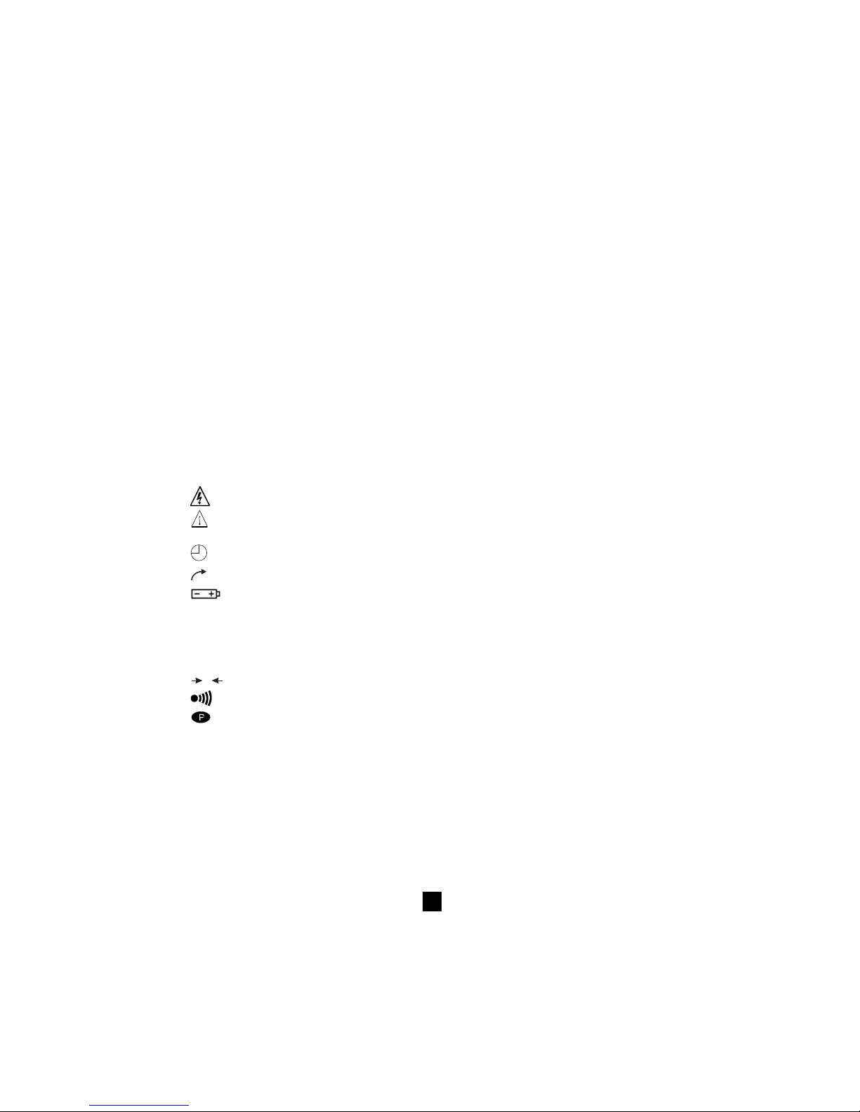
38
2.2.1 Digital display
The main display indicates values when carrying out insulation measurement (resistance, DAR and PI,
capacitance), and continuity and resistance measurement.
The small digital display indicates the voltage measured or applied by the instrument.
During insulation measurement, the elapsed time or the output voltage is displayed.
After recording a set of data (C.A 6543), the small display also indicates the time and date in MR
(memory recall) mode. It also indicates the memory address with the OBJ. TEST number (see § 2.2.3.
Symbols).
2.2.2 Bar graph
The bar graph is active for insulation measurement (0.1 MΩ to 1 TΩ). It also serves to indicate the
battery charge, as well as the free memory space - one segment representing approximately 100 groups
of saved values.
2.2.3 Symbols
MEM/MR Memory address (C.A 6543): the number is displayed above, on the small digital display.
OBJ : TEST Memory address (C.A 6543), the number is displayed above on the small digital display.
COM Flashes on the screen when data is transmitted to the serial interface (C.A 6543) or remains
permanently displayed if there is a problem during transfer.
DAR/PI Indicates the mode chosen before insulation measurement or the results of these
measurements.
Dangerous voltage generated, V > 120 V.
!
External voltage present, symbol is activated after pressing START, if V > 25 VAC ±3 V or >
35 VDC
Activation of “time-controlled test” mode or clock adjustment when in SET-UP (C.A 6543)
2nd
Indicates that the second function of a button is to be used
Flashes if the battery voltage (C.A 6541) or the rechargeable battery (C.A 6543) is low. The
batteries should be replaced or the rechargeable battery should be recharged (See § 8
Maintenance).
The voltage is displayed on the small digital display for 2 seconds whilst the instrument
switches on. The main display indicates “ bat “. This test is carried out internally on a load
corresponding to that during functioning.
W
0
Signal that lead compensation is in effect
Warning buzzer is activated
Indicates that the automatic switch-off function has been deactivated
SMOOTH Smoothes the insulation measurements displayed
REMOTE Remote control via an interface (C.A 6543). In this mode, all the buttons and the rotary
switch on the instrument are non-functional , except for in the case of switching off the
instrument.
FUSE HI Flashes if the “ + “ input fuse is defective.
FUSE -G- Flashes if the “ G “ input fuse is defective.
Page 39

39
3. MEASUREMENT FUNCTIONS
3.1 AC / DC Voltage
Select any insulation, resistance or continuity measurement position with the rotary selector switch and
the device is automatically in AC / DC voltage measurement mode. The voltage is permanently measured
and is shown on the small display.
Proceeding with a measurement is prohibited if an external voltage is present at the terminals before
pressing START / STOP. Similarly, if an interference voltage is detected during measurement, the
measurement is stopped and the voltage indicated.
3.2 Insulation measurement
As soon as one of the MΩ positions has been selected, the main display shows “- - - - MΩ”, and the
small display indicates the voltage present at the device’s + and - terminals.
If the external voltage present at the device’s terminals exceeds the thresholds shown on the
table below, then pressing the yellow START / STOP button does not bring about insulation measurement
but instead triggers a discontinuous audible signal (beep, beep, beep, ...) and the ! symbol flashes for
2 seconds, then the device goes back to automatic voltage measurement.
If the external voltage present at the device terminals is below the thresholds shown below, then
insulation measurement can go ahead:
Test Max voltage allowed
voltage for measurement
50 V 8 V
100 V 16 V
250 V 50 V
500 V 50 V
1000 V 50 V
Pressing START immediately begins the measurement. The measurement value is displayed on the
main digital display and on the bar graph. An audible beep is given out every 10 seconds to indicate that
measurement is in progress.
If the generated voltage is liable to be dangerous (> 120 V), the
symbol is displayed.
If, during insulation measurement, an external voltage > 25 VAC ±3 V or 35VDC is detected, the
measurement is stopped as long as the voltage is applied to the instrument. The
!
symbol
flashes and the voltage value is indicated on the small digital display.
If the measurements fluctuate greatly, it is possible to use the SMOOTH function (see § 4.5).
By pressing the V-TIME button during measurement you can alternate between displaying, on the small
display, the duration of the voltage measurement and the exact voltage generated (see § 4.2).
Pressing the STOP button stops the measurement.
After the measurement has been stopped the main result remains displayed.
It is possible to scroll down all the other results available on the main display using the R-DAR-PI button.
This button can also be used before measurement is begun (see § 4.3).
If the “Time-controlled test” mode has been selected, the R (t) button makes it possible to access all the
saved interval measurements automatically. (see § 4.2 and 4.3).
If the ALARM function is activated, a buzzer is triggered as soon as the measurement crosses the
threshold programmed in the SET-UP configuration menu (see § 4.4).
!!!
Page 40
40
■■
■■
■ Display of values after measurement
The following information may be displayed:
R-DAR-PI button V-TIME button
Main Small Small display
Display display if the MR button is pressed (C.A 6543)
Resistance duration (min. sec) date, time, test voltage, OBJ : TEST
DAR duration (min. sec) date, time, test voltage, OBJ : TEST
PI duration (min. sec) date, time , test voltage, OBJ : TEST
Capacitance*
R(t) duration (min. sec) last voltage
* Capacitance (µF) measurement is only displayed after the measurement is finished and the circuit
has been discharged.
3.3 Continuity (40
ΩΩ
ΩΩ
Ω
) / resistance (400 k
ΩΩ
ΩΩ
Ω)
Continuity measurement is carried out on the 40 Ω current position (with a test current > 200 mA up to
20 Ω), resistance measurement on the 400 kΩ position (with a test current < 6 mA).
■■
■■
■ Once the selector switch has been turned to one of these 2 positions, the main display indicates
- - - -
ΩΩ
ΩΩ
Ω (for continuity) or - - - - k
Ω Ω
Ω Ω
Ω (for resistance ) and the small display indicates the voltage
present on the + and - terminals.
!
If the voltage is > 3 V AC/DC and the START / STOP button is pressed, the ϕ symbol flashes and
the audible alarm gives out beeps (for 2 seconds) telling you that the measurement was denied,
then the device goes back to its normal voltage measurement.
!
If the voltage is < 3 VAC and the START / STOP button is pressed, the measurement goes ahead.
■■
■■
■ The main display indicates the continuity or resistance value in progress and the small display
indicates the voltage present on the + and - terminals.
!
Buttons R-DAR-PI, V-TIME and SMOOTH are not active for these functions.
There is no automatic polarity change for continuity measurement.
If, during continuity or resistance measurement, an external voltage > 25 VAC ±3 V or 35VDC is
detected, the measurement is stopped whilst the voltage is applied to the instrument. The
!
symbol flashes and the voltage value is indicated on the small digital display.
If the ALARM function is activated, a buzzer is triggered as soon as the measurement crosses the
threshold programmed in the SET-UP configuration menu.
!
Page 41

41
4. SPECIAL FUNCTIONS
4.1
2nd
Button
Use this button to select the second function activated by the buttons, it is always associated with the
2nd
symbol.
This symbol disappears upon pressing the function button chosen, except if the ▼ button is activated.
In this case, it only disappears when the
2nd
button is pressed again or if other function buttons are
pressed. This allows you to rapidly decrease parameters with the ▼ button, without having to press the
2nd
button every time.
4.2 V-TIME /
Button
■■
■■
■ First function V-TIME
With this button, all the secondary information available can be displayed on the small display.
For insulation measurement:
- The time elapsed since the start of the measurement
- The voltage between the instrument’s + and - terminals
- Date, time, test voltage and OBJ :TEST number in memory recall mode (MR)
For resistance or continuity measurement:
- Voltage between the instrument’s + and – terminals
- Date, time, test voltage and OBJ :TEST number in memory recall mode (MR)
■■
■■
■ Second function
(time-controlled test)
- The small display indicates the measurement duration programmed in SET-UP, the
symbol lights
up. Pressing the START button commences measurement.
- The measurement duration is set to 15 minutes by default (programmed in during manufacturing).
- As soon as the measurement is commenced, the small display counts down the remaining duration of
the measurement.
Once this duration reaches zero, measurement stops.
As the time-controlled test is carried out, interval samples (resistance/voltage values as a function of
time) are automatically saved.
The time between each sample is set to 30 s by default, but this value can be changed in the SET-UP menu.
The samples are displayed with the R (t) function (see § 4.3) as long as a new measurement has not
been commenced. With each new measurement, the previous sample value is erased from the memory.
These sample values are saved with the last value of the resistance if used with the MEM (memory
storage) function.
If the selector switch’s position is altered, or if the STOP button is pressed during measurement,
then measurement is interrupted.
This function is only active for insulation measurement.
4.3 R-DAR-PI / R (t) Button
■■
■■
■ First function R-DAR-PI
The R-DAR-PI button allows automatic measurement of the Polarisation Index (PI) and the Dielectric
Absorption Ration (DAR).
These two parameters are particularly useful when monitoring the ageing of insulation on electrical
machines or on long cables for example.
!
Page 42

42
On these kinds of parts, measurement is disturbed at the beginning due to interference currents
(from capacitive charges, dielectric absorption) which eventually cancel each other out. Therefore,
in order to get an accurate measurement of the leakage current that is representative of the insulation,
it is necessary to carry out the measurement over a long period of time so as to reduce the influence
of any interference currents when measurement is commenced.
Next we calculate the ratios such as the PI or the DAR :
PI = R 10 min / R 1 min (2 values to take down during a 10 min. measurement)
DAR = R 1 min / R 30 s (2 values to take down during a 1 min. measurement)
The quality of insulation depends on the results found.
DAR PI State of the insulation
< 1.25 < 1 Inadequate, even
< 2 dangerous
< 1.6 < 4 Good
> 1.6 > 4 Excellent
■■
■■
■ Using the R-DAR-PI function
During or after measurement, the R-DAR-PI button allows you to scroll through the following values:
- DAR (for measurements lasting > 1 min)
- PI (for measurements lasting > 10 min)
- Capacitance in µF (only after the measurement has stopped and the circuit has been discharged)
- Insulation resistance in MΩ, GΩ or TΩ
Automatic measurement of DAR or PI:
If the R-DAR-PI button is pressed when in voltage measurement mode before proceeding with a
measurement, then the following is displayed:
- - - - MΩ → DAR - - - - → PI - - - -
↑
Depending on the choices (DAR or PI), the measurement goes as follows:
a) DAR : press START → the DAR symbol flashes and the display indicates “- - - -” as long as the
calculation of the coefficient is not possible (t < 1 mn).
e.g. : DAR
- - - -
After 1 min, measurement stops and the main display automatically shows the DAR value.
During or after measurement, the R-DAR-PI button can be used to see the insulation measurement
carried out, but it does not give the PI value since the measurement has not lasted long enough.
b) PI : press START → the PI symbol flashes and the display shows “- - - -” as long as the calculation
of the coefficient is not possible (t < 10 mn).
e.g. : PI
- - - -
After 10 min, measurement stops and the main display automatically shows the PI value .
During and after measurement, the R-DAR-PI button makes it possible to display the DAR (after
1 min), the PI (after 10 mn) and the insulation measurement.
Page 43

43
Note : If during DAR or PI measurement (automatic or not), a high external interference voltage
becomes present, or the insulation resistance goes off the device’s measurement range, then
the DAR or PI measurements are interrupted and the screen indicates:
DAR MΩ
or
PI MΩ
Note : The 10 min/ 1 min measurement durations for PI calculation can be modified in the SETUP menu (see § 4.7), allowing adaptation to possible changes in standards or to suit a particular
application.
■■
■■
■ Second function R (t)
The R(t) button is used to access the interval insulation resistance values as a function of time, after a
measurement in “Time-controlled test” mode
(see § 4.2).
The time between each saved sample is programmed in the SET-UP menu.
This function is also available on model C.A 6541 which has neither a read-write memory for saving
measured data, nor an interface for data retrieval from the instrument by a PC.
On the C.A 6541, up to 20 samples can be recorded by the instrument during
measurement when
sampling at the rate chosen in SET-UP (the default value is 30 seconds).
It is possible to save more than 20 samples, available processing memory space permitting.
On the C.A 6543, the number of samples that can be saved is only limited by the read-write memory
space available.
After pressing the R(t) button, the instrument is in display mode:
- the small display indicates the time 00:30 (if the sampling frequency is 30 s)
- the main display shows the corresponding R value.
Using the V-TIME button it is possible to alternate between the time and voltage (on the small display),
associated with the R value on the main display.
The
▲
▼
button is used to scroll down through the all the samples saved during measurement. This makes
it possible to read off the information in order to draw out R(t) and an V(t) graphs.
This makes it possible to carry out R(t) analysis on-site, without a printer or a PC.
Pressing the R(t) or the R-DAR-PI again exits from this function
4.4
✻✻
✻✻
✻ / ALARM Button
■■
■■
■ First function ✻
This function allows the display back-light to be turned on or off.
■■
■■
■ Second function ALARM
Activates/deactivates the ALARM function. The corresponding symbol is displayed when activated.
If this function is activated and the high or low threshold value programmed in the SET-UP menu is
crossed, the ALARM symbol flashes and the buzzer (if activated) sounds continually.
It is possible to program a different limit in each function and these limits will be stored in memory after
the device is switched off.
Page 44

44
4.5
▼
/ SMOOTH Button
■■
■■
■ First function
▼
Used to select the desired parameter to be modified – the selected parameter flashes.
It is modified using the
▲
▼
button (see § 4.6).
■■
■■
■ Second function SMOOTH
Used to activate a digital filter for insulation measurement. It only has an effect on the displayed values
(which are smoothed) and not the actual measurements.
This function is useful for instances when the displayed insulation values are highly unstable, brought
about due to a capacitive component in the tested element for example.
4.6
▲
▼
Button
This function is used to change the flashing parameters being displayed, or to consult R (t) values (see
§ 4.3).
As a general rule, two figures (day, month, hour , min., sec., OBJ, TEST) flash.
The
▲▲
▲▲
▲ and
▼▼
▼▼
▼ functions have a “follow-on” mode, i.e.: as soon as the high or low modification limit is
reached, the parameter to be modified switches automatically to the following low or high limit.
■■
■■
■ First function
▲▲
▲▲
▲ : By pressing the button briefly, the displayed number can be increased unit by
unit.
When pressed for a longer time, the number is increased at a faster rate.
■■
■■
■ Second function
▼▼
▼▼
▼ : By pressing the button briefly, the displayed number can be decreased unit by
unit.
When pressed for a longer time, the number is decreased at a faster rate.
Unlike all the other second functions of other buttons, it is not necessary to press the
2nd
button
each time to get to the ▼ function. The
2nd
symbol remains displayed and thus valid for the ▼
function (only), as long as the user does not deactivate it by pressing
2nd
or another button.
4.7 SET- UP function
This function, found on the rotary selector switch, is used to alter the device configuration by directly
accessing the parameters to be modified.
After having selected SET-UP with the rotary selector switch:
- all the display segments are lit up for 1 second,
- the software version number is displayed
- the instrument serial number is displayed
- PUSH comes up on the small display and btn on the main display, inviting the operator to press a
button.
The SET-UP function is used to directly access the parameters to be modified, by pressing the
corresponding button:
- After having pressed a button, the figures or the symbols corresponding to the selected function
appear on the screen.
- The figures or the symbols that can be modified flash on the screen. The usual modification procedure
using the
▼
and
▲
▼
buttons should be followed.
- All the parameters are immediately and permanently saved.
The table on the following page defines the buttons that are functional when in SET-UP, and the
corresponding display with the possible range of adjustment.
Page 45

45
Parameters Command button Display
to modify main small symbols values
Duration of
15 : 00 min. sec, 1 - 59 min
“ time-controlled test”
1st and 2nd times for R-DAR-PI second time first time min : sec 00 : 59
PI calculation (10 min) (1 min)
Time between interval
samples in
R (t) 00 : 30 min : sec 5 s - 10 min
“ time-controlled test “
Limit for MΩ-50 V ALARM 50 kΩ 50 V ALARM < 2 k-200 G and </>
Limit for MΩ-100 V ALARM (2
nd
press) 100 kΩ 100 V ALARM < 4 k-400 G and </>
Limit for MΩ-250 V ALARM (3
rd
press) 250 kΩ 250 V ALARM < 10 k-1 T and </>
Limit for MΩ-500 V ALARM (4
th
press) 500 kΩ 500 V ALARM < 20 k-2 T and </>
Limit for MΩ-1000 V ALARM (5th press) 1000 kΩ 1000 V ALARM < 40 k-4 T and </>
Limit for 400 kΩ
ALARM (6th press) 100 kΩ rES ALARM <
0.01-400 kΩ
(resistance measurement) and </>
Limit for 40 Ω
ALARM (7th press) 2 Ω Cont ALARM < 0.01-40 Ω and </>
(continuity measurement)
Time V-TIME 12 :55
hh(0-23)
mn (0-59)
Date (European version) V-TIME (2nd press) 17.03 1999 jj.mm .aaaa
Version : USA, European V-TIME (3rd press) USA/Euro USA/Euro
Memory wipe MEM then MEM (2 s) cLr ALL MEM
Selective wiping of MEM then
▼
and
▲
▼
cLr OBJ : TEST MEM +
00...99
memory and MEM (2 s) number OBJ : TEST
300...9600
Baud PRINT 9600 bAUd
or "parallel"
Buzzer
✻
On
On / OFF
Auto switch-off ✻ (2
nd
press) On
On / OFF
Compensation ✻ (3
rd
press) - - - - On
W
0
On / OFF
then ▲ and START (value if START) and 0.01-5 Ω
Default configuration
✻ (4
th
press)
DFLt SEt
then START
Barring of insulation test ✻ (5
th
press) On 50 V On / OFF
Barring of insulation test ✻ (6
th
press) On 100 V On / OFF
Barring of insulation test ✻ (7
th
press) On 250 V On / OFF
Barring of insulation test ✻ (8
th
press) On 500 V On / OFF
Barring of insulation test ✻ (9
th
press) On 1000 V On / OFF
The values shown on this table, in the “ Display / main” and “Display / small” columns, are the default
values programmed in during manufacturing. In case they are accidentally changed, it is possible to get
them back: see § 4.7.4.
Page 46

46
4.7.1 Wiping the memory
In SET-UP, press the MEM button:
- The MEM symbol flashes
- The small display indicates ALL
- The main display indicates cLR
To wipe the entire memory, press the MEM button again for 2 seconds:
- The MEM symbol is displayed without flashing
- The main display indicates FrEE
To wipe the contents of a specific OBJ : TEST number:
- Select the number using the
▼
and
▲
▼
buttons
- cLr remains displayed on the main display
Press the MEM button again for 2 seconds to wipe the contents:
- The OBJ : TEST number is indicated on the small display
- The main display indicates FrEE
4.7.2 Signaling speed in Bauds (RS 232)
In SET-UP, press the PRINT button.
The main display indicates the signalling speed in bauds, either 300, 600, 1200, 2400, 4800, 9600 or
Parallel.
On the small display, baud appears. The value can be changed using the
▲▲
▲▲
▲ and
▼ ▼
▼ ▼
▼ buttons.
The display of “Parallel” means that parallel mode has been selected, for printing on a parallel printer via
the serial-to-parallel adapter (RS 232-Centronics).
4.7.3 Lead resistance compensation
In SET-UP, press the ✻ button three times:
The
W
0
symbol appears and the small display indicates On. It is possible to select OFF with the
▲
▼
button. In this instance, the lead resistance will not be subtracted when carrying out continuity measurement.
To memorise the lead resistance:
- Connect them together and press START (in SET-UP position
W
0
)
- The resistance of the leads will be memorised and indicated on the main display
Note :
- This value is stored in memory, even when the instrument is switched off.
- The lead compensation only comes into effect when carrying out continuity measurement.
- To activate/deactivate this function, simply select On or OFF on the small display with the
▲
▼
button.
- The memorised value will be stored and displayed on the main display, but can be activated or
deactivated, depending on what the small display indicates.
- Values between 0 and 5 Ω can be saved for leads compensation. Beyond this value, nothing is saved.
4.7.4 Default device configuration
In SET-UP, press the ✻ button four times:
- The small display indicates SEt (flashing).
- The main display indicates DFLt
Press START to select the default configuration settings (see the previous table).
Page 47

47
4.7.5 Barring of insulation measurement
This function prohibits insulation measurement from being carried out at certain test voltages. This
makes it possible the entrust the instrument to less experienced operators, for specific applications for
example (telephone ...).
In SET-UP, press ✻ 5 times or more (depending on voltage to be barred):
- The test voltages appear in succession on the small display with the ✻ button and On/OFF on the
main display.
- Choose On or OFF using the
▲
▼
button for each test voltage, to bar (OFF) or to reinstate (On) the
access to the insulation tests at these voltages.
5. USE
5.1 Measurement procedure
■ Star t up the device by selecting the corresponding position (MΩ, 40 Ω
or 400 kΩ) with the
selector switch. All the segments on the LCD screen are displayed, then the battery (or rechargeable
battery) voltage.
■ Connect the leads to the + and – terminals and the points of measurement.
■ The input voltage is constantly measured and displayed on the small display.
If an external voltage is present that is greater than the thresholds described in § 5.2, 5.3 and 5.4,
then measurement is prohibited.
■ Pressing START/STOP starts measurement.
■ Pressing START/STOP once again stops measurement. The last result remains displayed until the
next measurement or turn of the selector switch.
If a voltage > 25 VAC or 35 VDC is detected during all measurements, the instrument indicates this
voltage on the small display, the warning symbol flashes and the measurement in progress is stopped.
Note : There are several special functions that can be used. (see § 4).
5.2 Insulation measurement (see § 3.2)
When using this function, the instrument can measure insulation from 1 kΩ to 40 GΩ at a test voltage
of 50 V, 100 V, 250 V and up to 1 TΩ at 500 V and 1000 V.
■ Select, with the rotating switch, MΩ-50 V, or MΩ-100 V, or MΩ-500 V, or MΩ-1000 V
■ Connect the instrument to the insulator to be tested. If the voltage present exceeds 8 V for M
ΩΩ
ΩΩ
Ω-50
V, or 16 V for M
ΩΩ
ΩΩ
Ω-100 V, or 25 V at all the other test voltages, then measurement is prohibited.
■ Start the measurement and read-off the results.
It is possible to scroll through the results on the main display with the R-DAR-PI button, or on the small
display with the V-TIME button (see § 3.2).
Using R (t) when carrying out a ‘time-controlled test’, it is possible to scroll through the interval
measurement values saved at the sampling rate specified in SET-UP. These samples are available until
another measurement is got underway or the selector switch is turned. (see § 4.3)
When measuring high levels of insulation (> 1 G
ΩΩ
ΩΩ
Ω), it is advised that the guard terminal should be
used to eliminate the influence of surface leakage currents. The guard is connected, between the two
measurement contact points, to the surface susceptible to surface currents, i.e. dusty or damp cable or
transformer insulation. In this case, croc-clips are preferable to test-probes held in the hand. (see § 11).
As soon as insulation measurement is stopped, the test circuit is automatically discharged over the
instrument’s internal resistance.
Page 48

48
5.3 Continuity measurement (see § 3.3)
In this function, the measurement current is > 200 mA from 0 to 20 Ω and > 140 mA from 20 to 40 Ω.
This measurement serves to test the low resistance of PE ground cables for example.
The measurement ranges increase automatically up to 40 Ω with a maximum resolution of 0.01 Ω.
■ Select 40 Ω position with rotary switch
■ Connect the instrument to the test object
■ If the voltage present is > 3 V, then measurement is prohibited
■ Start the measurement and read-off the results.
NOTE : It is possible to compensate for the lead resistance (see § 4.10.3)
The R-DAR-PI and V-TIME buttons are not active for this function.
There is no automatic polarity change in continuity measurement.
5.4 Resistance measurement (see § 3.3)
In this function, the measurement current is limited to 6 mA. The measurement ranges increase
automatically in increments up to 400 kΩ with maximum resolution of 0.01 Ω.
■ Select 400 kΩ position with the rotary switch
■ Connect the instrument to the test object
■ If the voltage present is > 3 V, then measurement is prohibited
■ Start the measurement and read-off the results
During measurement, the potential difference at the input is indicated on the small display (useful for
measurement of multi-junction components: thyristors, high voltage diodes...).
The open circuit voltage is equal to the voltage of the battery (C.A 6541) or rechargeable battery voltage
(C.A 6543).
NOTE : the R-DAR-PI and V-TIME buttons are not active in this function.
5.5 Capacitance measurement
Capacitance measurement is automatically carried out during insulation measurement, and is displayed
after the measurement is stopped and the circuit is discharged, using the R-DAR-PI button.
!
!
Page 49
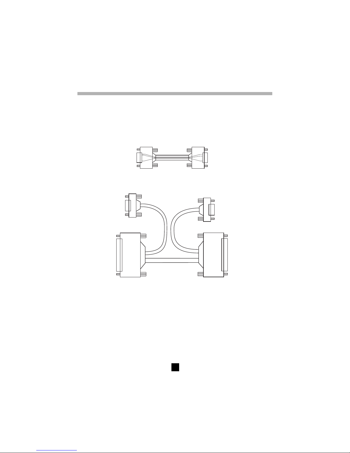
49
6. MEMORY / RS 232 (C.A 6543)
6.1 RS 232 Specifications
■ The signalling speed in Bauds can be set to 300, 600, 1200, 2400, 4800, 9600, or “Parallel” for the
printing of results on parallel printers via the optional serial-to-parallel adapter.
This setting is carried out in the SET-UP menu (see § 4.7)
■ Data format: 8 data bits , 1 stop bit, without parity, Xon / Xoff protocol
■ Serial printer connection
9pinfemaleconnector
toC.A6543
9pinmaleconnector
toserialprinter
2
2
3
3
5
5
Frontview
Frontview
■ Connection to a PC or to a parallel printer.
9-pin connector to PC
➂
➁
25-pin connector to PC or
serial-to-parallel adapter
➀
25-pin connector
9-pin connector to C.A 6543
Necessary links DB9
➔➔
➔➔
➔ B25 (
➀➀
➀➀
➀
→→
→→
→
➁➁
➁➁
➁)
■■
■■
■ DB25
➔➔
➔➔
➔ DB9 conversion (
➁➁
➁➁
➁
→→
→→
→
➂➂
➂➂
➂):
(null cable - standard modem) :
1 ➔ 8 6 ➔ 20 2 ➔ 3
2 ➔ 2 7 ➔ 5 3 ➔ 2
3 ➔ 3 8 ➔ 4 7 ➔ 5
4 ➔ 6 9 ➔ 22
5 ➔ 7
6.2 Saving / recalling values ( MEM/MR button)
6.2.1 First function MEM (save)
With this function results may be recorded on the device’s read-write memory.
These results are stored under addresses defined by an object number(OBJ) and a test number (TEST).
Page 50

50
An object represents a ‘box’ into which we can place 99 tests. Thus, an object can represent a machine
or an installation upon which a certain number of various measurements (insulation, resistance, continuity)
are carried out.
1. When the button is pressed, the MEM symbol flashes and the small display indicates the first free
OBJ : TEST number, e.g. 02 : 01. The main display indicates FrEE.
The OBJ number is the same as that of the last saved measurement, but the TEST number goes up
in 1’s.
It is always possible to modify OBJ : TEST with ▼ and
▲
▼
.
If the user happens to select a memory address that is already occupied, then OCC appears on the
main screen.
If a new OBJ is selected, TEST goes back to 01.
2. By pressing MEM once again, the present measurement results will be recorded in the selected
memory address (occupied or otherwise). The MEM symbol stops flashing and remains displayed.
The time and the date of this recording are memorised with the available data (R, V, t).
If a button other than MEM or the selector switch is activated before pressing MEM a second
time, the instrument exits from MEM mode without having saved the results.
3. If a time-controlled test has been carried out, interval values (samples) are available (see § 4.3). They
are automatically saved under the same OBJ : TEST number as the final measurement.
■■
■■
■ Estimation of the memory capacity:
Total memory space : 128 kb
Data management : 8 kb
Free memory space : 120 kb
An insulation measurement result takes up approximately 80 bytes.
For a “time-controlled test” , a sample takes up 10 more bytes.
A resistance or continuity measurement takes up 26 bytes.
It is therefore possible to record about 1500 insulation measurements or about 4000 resistance or
continuity tests.
■■
■■
■ Free memory space
This function is automatically activated when a result is saved.
Press MEM once in order to get the following free OBJ. TEST number; the bar graph indication is in
proportion to the available free memory space.
- If the entire memory is free, all of the bar graph segments show up.
- If the entire memory is full, the left arrow to the left of the bar graph flashes.
- As soon as the saving is over with, the bar graph disappears.
Each segment of the bar graph equates to approximately 50 recordings.
6.2.2 Second function MR
With the MR function it is possible to recall any saved data from the memory, no matter the position of
the rotary selector switch.
■ When the button is pressed, the MR symbol is displayed (without flashing).
The small display indicates the last OBJ : TEST number to be assigned, e.g. 02 :11.
02 “11” flashes opposite the TEST symbol, the usual modification procedure using the
▼
and
▲
▼
buttons should be used to select the desired OBJ : TEST number.
Page 51

51
If a new is OBJ is selected, TEST is automatically set to the maximum memorised number.
At this stage it is possible to consult the entire memory with the
▼
and
▲
▼
buttons, since the
measurement values corresponding to the selected OBJ : TEST number are displayed on the main
display. It is possible to scroll down through them with the R-DAR-PI button.
■ The V-TIME button is active and gives access to the date / time / V / OBJ-TEST number for each
result.
If the recording selected by the OBJ : TEST number corresponds to a time-controlled test, the R
(t) values can be accessed by pressing the R (t) button. The small display changes and indicates
min : sec (time of 1st sample) and the symbol
flashes on the screen. You can scroll through the
other samples with the
▲
▼
.button.
To exit from R (t) mode and return to the normal memory recall mode (OBJ : TEST), press R (t)
or R-DAR-PI again.
!
To exit the MR function, press the MR button once again or turn the selector switch.
Page 52

52
6.3 Printing out measured values (PRINT/PRINT MEM button) (C.A 6543)
If you use a serial printer, choose the appropriate communication speed in the SET-UP menu, between
300...9600 bauds, then program the printer to the format run by the instrument (see § 6.1).
If you are using a parallel printer, you should set the signalling speed to “Parallel” when in SET-UP and
use the serial-to-parallel adapter that comes as an optional item (to plug in series the supplied cable +
adapter + Centronics printer cable).
There are two different printing modes possible :
- Instantaneous printing of measurement (PRINT)
- Printing of recorded data (PRINT memory)
If the data transmission to the printer is successful, the COM symbol flashes on the screen.
If a problem is experienced, the COM symbol remains permanently on the LCD screen without flashing.
6.3.1 Instantaneous printing of measurements (PRINT button)
Following a measurement or after accessing values in MR mode, use the PRINT function to print-off the
measurement results.
Pressing the button brings about the printing of:
- 1 set of measurements (U/R/DAR/PI/date/time) for normal tests,
- the R(t) values if the ‘time-controlled test’ has been used.
To stop printing, alter the position of the selector switch.
According to the function used, the following models are obtained:
■■
■■
■ Insulation measurement
CHAUVIN ARNOUX C.A 6543
Instrument number: 000 001
INSULATION RESISTANCE TEST
OBJECT : 01 TEST : 01 (only printed in MR mode)
Description : .................................................
.....................................................................
Date : ......................................... 31.03.1998
Start time: .......................................... 14 :55
Test duration: ....................... 15 min. 30 sec
Temperature : .............................°C .........°F
Relative humidity : ....................................%
Test voltage :..................................... 1000 V
Insulation resistance (R) : ........ 385 GOhm
DAR (R 1'/R 30") :............................... 1.234
PI (R 10'/R 1") : ................................... 2.345
Comments: ..................................................
.....................................................................
Date of next test : .......................... /..../.......
After a ‘time-controlled test’ other results are printed (inter val samples) :
Time Resistance Voltage
00 : 30 35.94 GOhm 1005 V
01 : 00 42.00 GOhm 1005 V
01 : 30 43.50 GOhm 1005 V
etc... A space for the operator to fill in their signature
comes at the end of the printout.
!
Page 53

53
■■
■■
■ Continuity or resistance measurement
CHAUVIN ARNOUX C.A 6543
Instrument number : 000 001
CONTINUITY TEST or RESISTANCE TEST
OBJECT : 01 TEST : 01 (only printed in MR)
Description: ..................................................
.....................................................................
Date : ......................................... 31.03.1998
Start time : ....................................... 14 : 55
Test current : ................................ > 200 mA
Lead compensation : ........................ 0.12 Ω
Potential difference: ............................. 0.9 V
Continuity or Resistance : ................ 0.45 Ω
Comments : .................................................
.....................................................................
.....................................................................
Date of next test : .......................... /..../.......
A space for the operator to fill in their signature comes at the end of the printout.
6.3.2 Printing of memorised data (PRINT MEM button)
Use this function to print out the contents of the device’s read-write memory.
The small display indicates 01 :01 for the OBJ : TEST number (starting address of printing).
The main display indicates the last recording in memory (the end address of printing).
e.g. 12 : 06;
01 flashes opposite the OBJ position, the usual modification procedure should be used (
▼
and
▲
▼
buttons) in order to define the start/end addresses of the print-out.
To quit without printing, alter the position of the selector switch.
To go ahead with printing, press the PRINT button once more.
To stop printing, alter the position of the selector switch.
Only the main results are printed out.
Example :
CHAUVIN ARNOUX C.A 6543
Instrument number : 000 001
CONTINUITY TEST
OBJECT : 01 TEST : 01
Date : ........................................ 31.03.1998
Start time : .......................................... 14:55
Continuity : ....................................... 0.45 Ω
CONTINUITY TEST
OBJECT : 01 TEST : 02
Date : ........................................ 31.03.1998
Start time: ........................................... 14:55
Continuity : ........................................ 0.91 Ω
INSUALTION RESISTANCE TEST
OBJECT : 01 TEST : 03
Date : ........................................ 31.03.1998
Page 54

54
Start time: ............................................14:55
Test duration: ........................ 15 min 30 sec
Temperature : ............................ °C .........°F
Relative humidity: .....................................%
Test voltage: ..................................... 1000 V
Insulation resistance (IR) : ............ 385 GΩ
DAR (RI 1’/30“) : ................................. 1.234
PI (RI 10’/RI1’) : .................................. 2.345
Comments : .................................................
.....................................................................
.....................................................................
A space for the operator to fill in their signature comes at the end of the printout.
6.4 Printing with the serial-to-parallel adapter
1. Connect the null - modem RS232 cable to the C.A 6543
2. Connect the cable to the adapter, then the adapter to the printer cable
3. Switch on the printer
4. Switch on the C.A 6543
5. To start printing out values that haven’t been saved (immediate printing), press PRINT after a
measurement.
6. To start printing out saved measurements, press the “PRINT MEM” button
!
WARNING: This adapter is designed exclusively for use with the C.A 6543 and is not suitable
for any other application.
7. SPECIFICATIONS
7.1 Reference conditions
Influence quantity Reference values
Temperature 23°C +/- 3°K
Relative humidity 45 to 55 %
Supply voltage 9 to 12 V
Frequency range DC and 15.3...65 Hz
Parallel resistance on the resistor 0 µF
Electric field nil
Magnetic field < 40 A/m
7.2 Specifications per function
7.2.1 Voltage
Measurement range Resolution Frequency range
1... ... 1000 V 1 V DC / 16 ... 420 Hz
Page 55

55
■■
■■
■ Accuracy : ±1% R ±3 cts, AC sinusoidal or DC voltage
■■
■■
■ Input resistance : approx. 750 kΩ
WARNING: This instrument is Cat III 600 V, according to EN 61010-1. It shall not be connected to
voltages > 600 V in relation to the earth.
7.2.2 Insulation resistance
■■
■■
■ Method: Voltage-current method according to EN 61557-2
■■
■■
■ Nominal output voltage: 50, 100, 250, 500, 1000 VDC
■■
■■
■ Open-circuit voltage : ≤ 1.1 x Vn ± 5 V (50, 100, 250, 500, 1000 V)
■■
■■
■ Nominal current: > 1 mADC at the nominal voltage
■■
■■
■ Short-circuit current: < 6 mADC
■■
■■
■ Max. overvoltage: Urms max. = 1200 V AC and DC for 10 seconds between the “+” and “-” terminals
660 V AC and DC between the “G” and “-” or “G” and “+” terminals
■■
■■
■ Measurement ranges :
50 V : 2 kΩ... 200 GΩ
100 V : 4 kΩ... 400 GΩ
250 V : 10 kΩ... 1 TΩ
500 V : 20 kΩ... 2 TΩ
1000 V : 40 kΩ... 4 TΩ
Range 2 ... 999 kΩ
4.00..39.99 40,0..399,9
400...999 MΩ
4.00..39.99 40.0..399.9
400...999 GΩ
1.000..3.999
MΩ MΩ
1.000..3.999
GΩ GΩ 1.000...3.999
MΩ
GΩ TΩ
Resolution 1 kΩ 10 kΩ 100 kΩ 1 MΩ 10 MΩ 100 MΩ 1 GΩ
Voltage
50, 100, 250 50, 100, 250 50, 100, 250, 50, 100, 250, 50, 100, 250, 50, 100, 250, 250 V,
500, 1000 V 500, 1000 V 500, 1000 V 500, 1000 V 500, 1000 V 500, 1000 V 500, 1000 V
Accuracy ±(5% L +3 ct) ±(15% L +10 ct)
DC voltage measurement after insulation test
■■
■■
■ DC Voltage range: 25...1000 V
■■
■■
■ Resolution : 0.5% VDC
■■
■■
■ Accuracy: ±1% R ±3 cts
■■
■■
■ Voltage Vs load curve
Capacitance measurement (following the discharging of test object)
■■
■■
■ Range : 0.005...4.999 µF
■■
■■
■ Resolution: 1 nF
■■
■■
■ Accuracy : ± (10% + 1 ct)
Graphs showing the typical changes in test voltage as a function of the load
50 V test voltage
0
100
90
80
70
60
Resistance (kW)
Ouput voltage (V)
50
40
30
20
10
0
10
20
30
40
50
60
!
Page 56

56
100 V test voltage
0
100
90
80
70
60
Resistance (kW)
Ouput voltage (V)
50
40
30
20
10
0
20
40
60
80
100
120
250 V test voltage
0
250
200
150
100
50
0
Resistance (kW)
Ouput voltage (V)
50
100
150
200
250
300
500 V test voltage
0
500
400
300
200
100
0
Resistance (kW)
Ouput voltage (V)
100
200
300
400
500
600
Page 57

57
1000 V test voltage
0
1000
800
600
400
200
50
Resistance (kW)
Ouput voltage (V)
200
400
600
800
1000
1200
■■
■■
■ Typical settling time of the measurement as a function of the elements tested
These values include the influences on the auto-range and supply voltage regulation system due to the
charge of the capacitive component.
Non-capacitive load Load with 1 µF capacitor
1 MΩ insulation 7 s 7s
500 GΩ insulation 17 s 20 s
■■
■■
■ Discharge time of the tested element (across a 750 k
Ω Ω
Ω Ω
Ω internal resistance) up to 25 V
Initial voltage Discharge time
1000 V 2.8 s
500 V 2.2 s
250 V 1.7 s
100 V 1 s
50 V 0.5 s
■■
■■
■ Range of DAR and PI ratios : 0.000 to 9.999
Accuracy: ±5%
7.2.3 Continuity
■■
■■
■ Method: Voltage-current method according to EN 61557-4
■■
■■
■ Open-circuit voltage: Max. 12.4 VDC (< 15 V with external supply)
■■
■■
■ Short-circuit current: > 200 mADC
■■
■■
■ Max. voltage surge: 1200 V AC and DC for 10 seconds between the “+” and “-” terminals
660 V AC and DC between the “G” and “-” or “G” and “+” terminals
■■
■■
■ Test lead compensation:
R∆ is measured for the test leads in short-circuit when in the SET-UP menu (see § 4.7), this value is
memorised and subtracted from all continuity measurements. The compensation is limited to 5 Ω.
R displayed = R measured - R∆
■■
■■
■ Continuity measurement range: 0.01 to 39.99 Ω
■■
■■
■ Resolution : 0.01 Ω
Page 58

58
■■
■■
■ Operating current: > 200 mA from 0.01 to 20.00 Ω and > 140 mA from 20.01 to 39.99 Ω
■■
■■
■ Accuracy : ±3% R ±4 cts
■■
■■
■ Max inductive load : 5 hrs without damage to the instrument
■■
■■
■ Max serial mode voltage: 3 VAC/DC; measurement is prohibited above this value
7.2.4 Resistance
■■
■■
■ Method : Voltage-current measurement
■■
■■
■ Open-circuit voltage: max. 12.4 VDC (< 15 V with external supply)
■■
■■
■ Short-circuit current : < 6 mA DC
■■
■■
■ Max. voltage surge: 1200 V AC and DC for 10 seconds between the “+” and “-” terminals
660 V AC and DC between the “G” and “-” or “G” and “+” terminals
■■
■■
■ Max serial mode voltage: 3 VAC or 3 VDC; measurement is prohibited above this value
Range 0.01..39.99 Ω 40.0..399.9 Ω 0.400..3.999 kΩ 4.00..39.99 kΩ 40.0..399.9 kΩ
Resolution 0.01 Ω 0.1 Ω 1 Ω 10 Ω 100 Ω
Accuracy ±3 % R ±3 cts
7.3 Power supply
■■
■■
■ The device supply is via:
- 8 x 1.5 V batteries, LR 14 (C.A 6541)
- Rechargeables battery NiMh (C.A 6543)
Recharge: 85 to 256 V / 50-60 Hz (electrical safety: 256 V Cat. III)
Instrument C.A 6541 C.A 6543
Measurement Average operating radius Average operating radius
Insulation measurement: 21, 000 x 5 s measurements 5, 000 x 5 s measurements
with 20 s pause, for normal load* (1) with 29 s pause, for normal load * (2)
Continuity measurement: 16 000 measurements lasting 5 s 4 000 measurements lasting 5 s
with pause of 20 s at nominal load * (1) with pause of 20 s at nominal load * (2)
* Normal load
: 1000 V/1 mA
(1) If we assume that a 10 minute long PI measurement is made 5 times a day, the operating radius will be 67 days (or
10 weeks or 2.5 months)
(2) If we assume that a 10 minute long PI measurement is made 5 times a day, the operating radius will be 16 days (or
2.5 weeks or 0.5 months)
■■
■■
■ Recharging time (C.A 6543)
4.5 hours to reach 100% of its capacity (Max. recharge time: 6 hours)
0.5 hours to reach 10% of its capacity (gives operating radius: 1 day approx.)
7.4 Environmental conditions
■■
■■
■ Operating range
-10 to 40°C, during recharging of batteries
-10 to 55°C, during measurement
20 to 80 % RH
■■
■■
■ Nominal temp. range
0 to 35°C
■■
■■
■ Storage :
-40 to 70°C
10 to 90 % RH
Page 59

59
■■
■■
■ Temperature influence on measurement accuracy (for all functions)
±0.15 % per °C
■■
■■
■ Altitude: < 2000 m
7.5 Mechanical specifications
■ Outside dimensions of casing (L x W x H): 240 x 185 x 110 mm
■ Weight : approx. 3.4 kg
7.6 Conformity to international standards
■ Electrical safety according to: EN 61010-1, EN 61557
■ Double insulation:
■ Pollution level: 2
■ Installation category: III
■ Max. voltage in relation to earth: 600 V
7.6.1. Electromagnetic Compatibility
■ Emissions and immunity in an industrial setting compliant with EN 61326-1.
7.6.2. Mechanical protection
IP 54 according to NF EN 60529
IK 04 according to NF EN 50102
8. MAINTENANCE
For maintenance, use only specified spare parts. The manufacturer will not be held responsible
for any accident occuring following a repair done other than by its After Sales Service or approved
repairers.
8.1. Upkeep
8.1.1. Replacing the batteries (C.A 6541)
The battery voltage comes up on the small digital display for 2 seconds when switching on the instrument.
The main display indicates “bAt”. This test is made internally on a load corresponding to that during
functioning.
Before making the measurement, make sure that the
symbol is not flashing on the screen. (after
the switching on stage the battery voltage appears for 2 seconds on the small display).
If this is not the case, it is essential that you should change all the batteries, taking all the necessary
precautions whilst opening the instrument.
Check that none of the terminals is connected and that the selector switch is definitely on OFF
before accessing the battery compartment found inside the instrument.
Exact type of batteries specified: LR14 (alkaline)
To open up the instrument, unscrew the 4 captive screws situated on the underside of the case. As soon
as they turn freely, place the instrument on a table and press on the screws to extract the front panel.
Turn over the instrument to entirely remove the front panel unit from the casing. The batteries are then
accessible at the back of the panel unit after having unscrewed the battery compartment’s two screws.
Take care not to damage the seal during removal and replacement of the front panel unit.
!
!
Page 60

60
8.1.2 Recharging the battery (C.A 6543)
If the
symbol appears flashing, then it is necessary to recharge the battery. Connect the
instrument to the mains AC network via the ➅ connector, charging starts automatically:
■ bAt on the small display and CHrG on the main display, signifies fast charging in progress
■ bAt on the small display and CHrG flashing on the main display, signifies slow charging (starts off
with fast charge, temperature conditions permitting)
■ bAt on the small display and FULL on the main display, signifies that charging is over.
If the instrument is started up and the battery voltage is > 8 V, then the normal use of the device is
permitted.
The battery should be changed by Manumesure or a repairer recognised by CHAUVIN ARNOUX
Changing the battery causes data to be lost from the memory. Press the MEM / MR button and
‘OFF’ is displayed. Procede with a total memory wipe in SET-UP (see § 4.7.1) so the MEM/MR functions
can be used again.
8.1.3 Replacing the fuses
If FUS HI or FUSE -G- flashes on the LCD when switching on or during continuity measurement, then
it is imperative that the corresponding fuses should be changed, taking all the necessary precautions
when opening up the instrument (see § 8.1.1 for opening procedure).
Check that none of the terminals are connected and that the selector switch is set to OFF before
opening up the device casing.
Exact types of fuses (on sticker in battery compartment) :
- + terminal fuse F1 (FUS HI) : F 2.5 A time delayed fuse – 1.2 kV - 8 x 50 mm - 15 kA
- G terminal fuse F2 (FUS G) : F 0.1 A fast fuse - 660 V – 6.3 x 32 mm - 20 kA
8.1.4 Cleaning
The instrument must be disconnected from any source of electricity.
Use a soft cloth lightly dampened with soapy water. Rinse with a wet cloth and then dry with a dry cloth
or a flow of air. Do not use alcohol, solvents or hydrocarbons.
8.1.5 Storage
If the instrument is not used for an extended time period (longer than two months), remove the battery
and store separately. (C.A 6541).
8.1.6 Calibration
Like all measuring or testing devices, the instrument must be checked regularly.
This instrument should be checked at least once a year. For checking and calibration, contact one of
our accredited metrology laboratories (information and contact details available on request), at our
Chauvin Arnoux subsidiary or the branch in your country.
8.1.7 Maintenance
For all repairs before or after expiry of warranty, please return the device to your distributor.
9. WARRANTY
Our guarantee is applicable for twelve months after the date on which the equipment is made available
(extract from our General Conditions of Sale, available on request).
!!!
!
!
Page 61

61
10. TO ORDER
C.A 6541 ................................................................................................................................ P01138901
Delivered with shoulder bag containing :
2 x 1.5 m safety leads - straight-straight (red + blue)
1 x 1.5 m guarded safety lead (black)
3 x croc-clips (red, blue and black)
1 x black test probe
8 x LR14 batteries
5 x condensed user’s manuals (1 per language)
and this user’s manual in 5 languages.
C.A 6543 ................................................................................................................................ P01138902
Delivered in shoulder bag containing:
1 cable DB9F-DB9F
1 adapter DB9M-DB9M
2 x 1.5 m safety leads – straight- straight (red + blue)
1 x1.5 m guarded safety lead (black)
3 x croc-clips (red, blue and black)
1 x black test probe
1 x 2 m mains lead
5 x condensed user’s manuals (1 per language)
and this user’s manual in 5 languages.
Accessories :
■ Remote control probe ....................................................................................................... P01101935
■ Set of 2 test probes (red + black) ..................................................................................P01295458Z
■ Set of 3 x 3 m safety leads (red + blue + black guarded) ............................................... P01295170
■ PC software (C.A 6543) ................................................................................................ P01101938A
■ Serial printer (C.A 6543) .................................................................................................. P01102903
■ Serial-to-parallel adapter (C.A 6543)................................................................................ P01101941
Spares :
■ 3 x 1.5 m safety leads straight-straight (red + blue + black guarded )........................... P01295171
■ 4 x croc-clips (red, black, blue, green) ............................................................................ P01101801
■ Shoulder bag N° 6 for accessories .................................................................................. P01298051
■ F 2.5 A - 1200 V – time delay fuse - 15 kA - 8 x 50 mm (set of 5) ................................ P01297071
■ F 0.1 A - 660 V – fast fuse - 20 kA - 6.3 x 32 mm (set of10) ......................................... P01297072
■ 9.6 V – 2.4 AH – NiMh Rechargeable battery .................................................................. P01296021
■ RS 232 PC cable DB 9F - DB 25F x2 .............................................................................. P01295172
■ RS 232 printer cable DB 9F - DB 9M N°01..................................................................... P01295173
■ Mains lead (no earth)........................................................................................................ P01295174
Page 62

62
Deutsch
Bedeutung des Zeichens
!
Achtung ! Beachten Sie vor Benutzung des Gerätes die Hinweise in der Bedienungsanleitung.
Falls die Anweisungen die in vorliegender Bedienungsanleitung nach diesem Zeichen erscheinen
nicht beachtet bzw. nicht ausgeführt werden, können körperliche Verletzungen verursacht bzw. das
Gerät und die Anlagen beschädigt werden.
Bedeutung des Zeichens
Das Gerät ist schutzisoliert bzw. durch eine verstärke Isolierung geschützt. Ein Anschluß an einem
Erdleiter ist für die Gewährleistung der elektrischen Sicherheit nicht erforderlich.
Bedeutung des Zeichens
ACHTUNG ! Gefahr von elektrischen Stromschlägen.
Die Spannung an mit diesem Symbol gekennzeichneten Teilen kann ≥ 120 V DC betragen. Aus
Sicherheitsgründen erscheint dieses Symbol in der LC-Anzeige wenn eine Prüfspannung erzeugt wird.
Wir danken Ihnen für das Vertrauen, dass Sie uns mit dem Kauf dieses Megohmmeter C.A 6541 und
C.A 6543 entgegengebracht haben. Damit die optimale Nutzung des Geräts gewährleistet ist:
n lesen diese Bedienungsanleitung sorgfältig durch,
n beachten Sie die Sicherheitshinweise.
!
SICHERHEITSHINWEISE
!
■ Beachten Sie die Betriebsbedingungen des Geräts: Temperatur, Feuchte, Meereshöhe,
Verschmutzungsgrad und Einsatzort.
■ Das Gerät kann an Installationen der Überspannungskategorie III, deren Spannung gegenüber Erde
600 V nicht übersteigt, eingesetzt werden. Geräte der Kategorie III erfüllen die strengen Sicherheitsund Zuverlässigkeitsanforderungen für Dauerbetrieb in festen Industrie-Elektroinstallationen (siehe
EN 61010).
■ Verwenden Sie nur Anschlusszubehör mit einer Betriebsspannung und einer
Überspannungskategorie, die mindestens derjenigen des Messgeräts entsprechen (600 V, Cat. III)
oder höher sind, und verwenden Sie ausschließlich Messzubehör, das die Sicherheitsnormen erfüllt
(EN 61010-2-032).
■ Verwenden Sie nur Sicherungen des angegebenen Typs und Werts (siehe § 8.1.3), da sonst das
Gerät beschädigt werden kann und die Garantie erlischt.
■ Schalten Sie das Gerät mit dem Schalter in Stellung OFF aus, wenn sie es längere Zeit nicht
benutzen.
■ Stellen Sie vor jedem Öffnen des Geräts sicher, dass keine Kabel angeschlossen sind und sich der
Schalter in Stellung OFF befindet.
■ Reparatur- oder Kalibrierarbeiten dürfen nur von entsprechend ausgebildeten und befugten Fachleuten
vorgenommen werden.
■ Mit dem CA 6543 ist keine Messung wahrend der Aufladung des Akkus moglich.
■ Eine Batterieaufladung ist unentbehrich vor metrologishen Tests.
Page 63

63
INHALTSÜBERSICHT
1. VORSTELLUNG ............................................................................................................................ 64
1.1 Megohmmeter C.A 6541 und C.A 6543 ................................................................................ 64
1.2 Zubehör .................................................................................................................................. 64
2. BESCHREIBUNG .......................................................................................................................... 66
2.1 Gehäuse ................................................................................................................................ 66
2.2 Anzeige .................................................................................................................................. 67
3. MESSUNGEN ................................................................................................................................. 69
3.1 AC-/DC-Spannung ................................................................................................................. 69
3.2 Isolationsmessungen............................................................................................................. 69
3.3 Durchgang (40 Ω
) / Widerstand (400 kΩ) ..................................................................... 70
4. SONDERFUNKTIONEN ................................................................................................................ 71
4.1 Taste
2nd
............................................................................................................................... 71
4.2 Taste V-TIME /
................................................................................................................... 71
4.3 Taste R-DAR-PI / R (t) .......................................................................................................... 71
4.4 Taste [ / ALARM ..................................................................................................................... 73
4.5 Taste ▼ / SMOOTH ............................................................................................................. 74
4.6 Taste
▲
▼
................................................................................................................................. 74
4.7 SET-UP - Funktion (Gerätekonfiguration) ............................................................................ 74
5. GERÄTEBENUTZUNG .................................................................................................................77
5.1 Ablauf einer Messung ............................................................................................................ 77
5.2 Isolationsmessung ................................................................................................................. 77
5.3 Durchgangsmessung ............................................................................................................ 78
5.4 Widerstandsmessung............................................................................................................ 78
5.5 Kapazitätsmessung ............................................................................................................... 78
6. SPEICHER / RS 232 (NUR C.A 6543) .......................................................................................... 79
6.1 Eigenschaften der RS 232-Schnittstelle ............................................................................... 79
6.2 Messwerte abspeichern bzw. aufrufen (Taste MEM/MR) .................................................... 79
6.3 Ausdruck von Messwerten (Taste PRINT/PRINT MEM) (nur C.A 6543) .......................... 82
6.4 Drucken mit dem Seriell/Parallel-Adapter ............................................................................. 84
7. TECHNISCHE DATEN ................................................................................................................... 84
7.1 Bezugsbedingungen .............................................................................................................. 84
7.2 Technische Daten der Messfunktionen ................................................................................ 84
7.3 Stromversorgung ................................................................................................................... 88
7.4 Klimabedingungen .................................................................................................................. 88
7.5 Mechanische Daten ............................................................................................................... 89
7.6 Normeneinhaltung .................................................................................................................. 89
8. WARTUNG / INSTANDHALTUNG ............................................................................................... 89
8.1. Wartung .................................................................................................................................. 89
9. GARANTIE ..................................................................................................................................... 90
10. BESTELLANGABEN ..................................................................................................................... 91
11. ANHANG...................................................................................................................................... 152
11.1 Vorderseite ........................................................................................................................... 152
11.2 Anwendungsbeispiele .......................................................................................................... 153
11.3 Zubehör ................................................................................................................................ 156
Page 64

64
1. VORSTELLUNG
1.1 Megohmmeter C.A 6541 und C.A 6543
Die Megohmmeter C.A 6541 und C.A 6543 sind tragbare Geräte in einem robusten, baustellentauglichen
Gehäuse mit Deckel, die über Batterien (C.A 6541) bzw. über einen Akku und am Wechselstromnetz
(C.A 6543) betrieben werden können.
Die Geräte ermöglichen folgende Messungen:
■ Spannung
■ Isolationswiderstand
■ Durchgang
■ Widerstand
■ Kapazität.
Die Megohmmeter sind Hilfsmittel zur Prüfung der Sicherheit von elektrischen Anlagen und Geräten.
Erfassung, Verarbeitung und Abspeicherung der Messwerte, sowie die Messwertanzeige und ihr Ausdruck
(C.A 6543) erfolgen mikroprozessorgesteuert.
Zu den zahlreichen Vorzügen der Geräte gehören:
■ digitale Filterfunktion bei Isolationsmessungen
■ ferngesteuertes Starten der Messung durch eine Prüfspitze mit Fernbedienung
■ automatische Messung der Spannung in allen Funktionen
■ automatisches Erkennen einer AC- oder DC-Fremdspannung an den Prüfklemmen, vor und während
der Messung, mit Abbruch bzw. Abschalten der Messung in jeder Funktion
■ Einstellung von Alarmschwellen für jede Messfunktion, mit akustischer Alarmgabe bei Über-/
Unterschreitung
■ Einstellung der Prüfdauer durch eingebauten Zeitgeber
■ Überlastschutz durch Sicherung, mit Anzeige falls die Sicherung defekt ist
■ hohe Sicherheit für den Bediener, da die Prüf-Hochspannung im gemessenen Kreis automatisch
abgebaut wird
■ automatische Abschaltung des Geräts bei Nichtbenutzung, um die Batterien (C.A 6541) bzw. den
Akku (C.A 6543) zu schonen
■ Anzeige des Batterie- (C.A 6541) bzw. Ladezustands (C.A 6543)
■ beleuchtete, großformatige LC-Anzeige mit zahlreichen Symbolen zur umfassenden Information
des Benutzers.
Das Megohmmeter C.A 6543 verfügt darüber hinaus über die folgenden zusätzlichen Eigenschaften:
■ Eingebauter Akku mit Netzladegerät
■ direkter Betrieb am Wechselstromnetz möglich
■ Messwertspeicher (128 KB), Echtzeituhr und serielle Schnittstelle
■ Steuerung aller Messfunktionen über PC (mit der optionalen Software MEGOHM VIEW )
■ Messwertausdruck über RS 232- oder Centronics-Schnittstelle.
1.2 Zubehör
■■
■■
■ Prüfspitze mit Fernbedienung (Option, siehe § 11.3)
Diese Prüfspitze wird über einen besonderen Steckverbinder angeschlossen.
Mit ihr lassen sich die Messungen über die gelbe START/STOP-Taste komplett steuern. Die Funktion
der Taste ist identisch zur START/STOP-Taste des Geräts.
Mit einer weiteren Taste auf der Rückseite der Prüfspitze lässt sich der Messpunkt beleuchten. Diese
Ausleuchtung mit ca. 500 Lux ist besonders praktisch, da Isolationsmessungen an stromlosen und
deswegen meist unbeleuchteten Anlagen vorzunehmen sind.
Page 65

65
■■
■■
■ PC-Software „Megohm View“ (Option für C.A 6543)
Diese Software hat die folgenden Funktionen:
- Übernahme von im Gerät gespeicherten Daten
- Verlaufskurve des Isolationswiderstands R (t) in Abhängigkeit von der Zeit darstellen
- Ausdrucken von Messprotokollen mit den individuellen Einstellungen des Benutzers
- Erzeugung von Textdateien zur Übernahme in Tabellenkalkulationsprogramme (z.B. ExcelTM, ...),
- Konfiguration und Steuerung des Geräts über die RS 232-Schnittstelle.
Die empfohlene Mindestausstattung des PC für diese Software ist ein 486DX100 - Prozessor.
■■
■■
■ Serieller Drucker (Option für C.A 6543)
Mit diesem kompakten Drucker lassen sich Messergebnisse oder Speicherinhalte direkt vor Ort
ausdrucken.
■■
■■
■ Adapter Seriell/Parallel
Mit dem als Zubehör erhältlichen RS232/Centronics-Adapter lässt sich die serielle RS232-Schnittstelle
in eine parallele Centronics-Druckerschnittstelle umwandeln. Damit kann man einen normalen PC-Drucker
für DIN A4-Blätter direkt anschließen und Messwerte bzw. Speicherinhalte ohne Umweg über einen PC
ausdrucken.
Page 66

66
2. BESCHREIBUNG
2.1 Gehäuse
Siehe hierzu die Geräteabbildungen im Anhang, § 11, am Ende der Anleitung.
2.1.1 C.A 6541 und C.A 6543
➀ 3 Sicherheitsbuchsen Ø 4 mm mit den Bezeichnungen „+“, „G“ und „-“
Neben der Buchse „-“ befinden sich zwei weitere Kontakte für den Anschluss der Prüfspitze mit
Fernbedienung (3-poliger Stecker)
➁ Drehschalter mit 9 Stellungen:
■ Off: Gerät ausschalten
■ MΩ - 50 V : Isolationsmessung bis 200 GΩ
■ MΩ - 100 V : Isolationsmessung bis 400 GΩ
■ MΩ - 250 V : Isolationsmessung bis 1 TΩ
■ MΩ - 500 V : Isolationsmessung bis 2 TΩ
■ MΩ - 1000 V : Isolationsmessung bis 4 TΩ
■ 400 KΩ: Widerstandsmessung
■ 40 Ω
: Durchgangsmessung
■ SET-UP: Einstellen der Geräte-Konfiguration
➂ Gelbe Taste START/STOP: Messung starten/stoppen
➃ 6 Tasten (C.A 6541) bzw. 8 Tasten (C.A 6543) aus Elastomer mit jeweils einer Haupt- und einer
Zweitfunktion:
2nd
Anwahl der Zweitfunktion (in gelber Kursivschrift unter den Tasten angegeben)
Hauptfunktion: Vor Isolationsmessungen, Auswahl der gewünschten Messart
R-DAR-PI
Umschaltung zwischen Widerstandsmessung, dielektrischer Verlustfaktor (DAR) und
Polarisationsindex (PI). Nach der Messung, Anzeige von R, DAR, PI und der Kapazität (µF).
R (t)
Zweitfunktion: Anzeige/Abwahl von Zwischenwerten des Isolationswiderstands, der
Prüfspannung und von Uhrzeit und Datum bei vorprogrammierter Prüfdauer (Die Tasten
V-TIME und
▲
▼
sind ebenfalls benutzbar).
V-TIME
Hauptfunktion: Bei Isolationsmessungen: Anzeige der Prüfdauer seit Messbeginn, danach
der tatsächlichen Prüfspannung. Bei Widerstands- oder Durchgangsmessung ist diese
Taste wirkungslos. Bei Speicherabruf (MR), Anzeige von Datum/Uhrzeit des gespeicherten
Messwerts, der exakten Prüfspannung und der Prüflings- bzw. Prüfungs-Nr. OBJ:TEST.
Zweitfunktion: Ein-/Ausschalten der Funktion „Programmierte Prüfdauer“.
✻ Hauptfunktion: Ein-/Ausschalten der Anzeigebeleuchtung
ALARM Zweitfunktion: Ein-/Ausschalten der im SET-UP programmierten Alarmfunktionen
▼
Hauptfunktion: Auswahl eines zu ändernden Parameters
SMOOTH Zweitfunktion: Ein-/Ausschalten der Messwertglättung bei Isolationsmessungen
Page 67
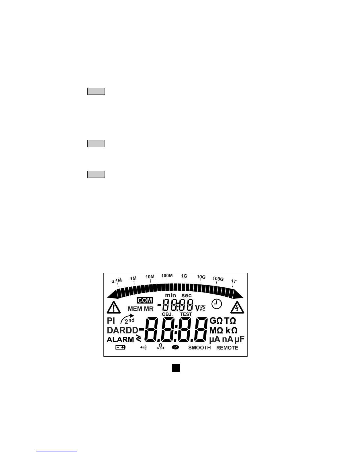
67
▲
Hauptfunktion: Erhöht den blinkend angezeigten Parameter, bzw. Blättern in der
Zwischenmesswert-Liste des Isolationswiderstands in der Funktion R(t).
▼ Zweitfunktion: Verringert den blinkend angezeigten Parameter, bzw. Blättern in der
Zwischenmesswert-Liste des Isolationswiderstands in der Funktion R(t).
Werden die Tasten ▲ oder ▼ ständig gedrückt, ändern sich die Parameterwerte in
größeren Schritten
■■
■■
■ Nur beim C.A 6543
MEM Hauptfunktion: Abspeichern der Messergebnisse
MR Zweitfunktion: Abruf der eingespeicherten Messwerte (in jeder Schalterstellung
möglich)
PRINT Hauptfunktion: Sofortiger Ausdruck des aktuellen Messergebnisses
PRINT Zweitfunktion: Ausdruck der gespeicherten Messwerte
MEM
➄ Beleuchtete Flüssigkristallanzeige
2.1.2 Nur beim C.A 6543
➅ Steckdose für Netzanschluss (Direktbetrieb am Netz oder Nachladen des Akkus)
➆ 9-poliger RS 232 - Stecker zum Anschluss an einen PC oder eines Druckers
Hinweis: Das Batterie- (C.A 6541) bzw. Akkufach (C.A 6543) befindet sich im Gehäuseinnern.
2.2 Anzeige
Page 68
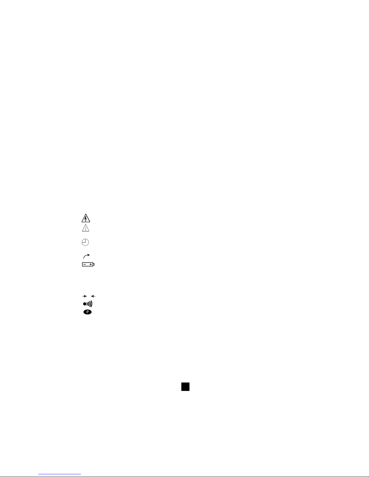
68
2.2.1 Digitalanzeige
In der großen Digitalanzeige erscheinen bei der Isolationsmessung die Messwerte für Widerstand R, DAR,
PI und Kapazität, sowie die Widerstandswerte bei Widerstands- und Durchgangsmessungen.
In der kleinen Anzeige erscheint die gemessene bzw. die vom Gerät erzeugte Spannung.
Bei Isolationsmessungen erscheint die bisher abgelaufene Prüfdauer bzw. die Ausgangsspannung am Gerät.
Nach Abspeicherung von Messwerten (C.A 6543) erscheinen bei Speicheraufruf (MR) Datum und Uhrzeit
der Messung in der kleinen Anzeige. Für die Eingabe einer Speicheradresse mit Prüflings- und Prüfungs-Nr.
OBJ:TEST wird ebenfalls die kleine Anzeige benutzt (siehe § 2.2.3. Symbole).
2.2.2 Bargraph
Der Bargraph dient zur Analoganzeige des Werts bei Isolationsmessungen (0,1 MΩ bis 1 TΩ). Mit ihm
wird auch der Ladezustand des Akkus bzw. die verfügbare Speicherkapazität angezeigt (ein Segment
entspricht etwa 100 Datensätzen).
2.2.3 Symboles
MEM/MR Symbole
MEM/MR Zeigen das Abspeichern (MEM) bzw. das Aufrufen von gespeicherten Werten (MR) an (nur C.A 6543)
OBJ:TEST Anzeige der Speicheradresse (C.A 6543), die Speicherplatz-Nr. erscheint in der oberen,
kleinen Digitalanzeige.
COM Blinkt während der Übertragung von Daten über die serielle Schnittstelle (nur C.A 6543)
bzw. erscheint ständig falls es Probleme bei der Datenübertragung gibt.
DAR/PI Zeigt an, welche Messart vor Isolationsmessungen gewählt wurde bzw. kennzeichnet die
Messwerte
Erzeugte Prüfspannung ist gefährlich : U > 120 V
!
Fremdspannung liegt an! Dieses Symbol erscheint nach Drücken der Taste START wenn
U > 25 VAC ±3 V oder U > 35 VDC.
Einschalten der „Programmierten Prüfdauer“ oder im SET-UP-Betrieb Einstellen der Uhrzeit
(nur C.A 6543)
2nd
Zeigt an, dass die Zweitfunktion der Taste angewählt ist
Blinkt bei schwacher Kapazität der Batterien (C.A 6541) bzw. des Akkus (C.A 6543). Batterien
ersetzen bzw. Akku nachladen (siehe § 8 Wartung).
Bei Einschalten des Geräts erscheint in der kleinen Digitalanzeige während 2 s die aktuelle
Versorgungsspannung. In der großen Anzeige erscheint der Schriftzug „bAt“. Diese Prüfung
der Versorgungsspannung erfolgt mit einer dem Messbetrieb entsprechenden Last.
W
0
Zeigt an, dass die Kompensation der Messkabel eingeschaltet ist
Zeigt an, dass der Summer eingeschaltet ist
Zeigt an, dass die automatische Abschaltung ausgeschaltet ist
SMOOTH Glättung der Messwerte bei Isolationsmessungen
REMOTE Gerät wird über PC-Schnittstelle ferngesteuert (nur C.A 6543). In diesem Fall sind alle
Tasten und der Drehschalter wirkungslos, bis auf die Funktion OFF (Abschalten des Geräts)
FUSE HI Blinkt bei defekter Sicherung im Eingangskreis „+“
FUSE -G- Blinkt bei defekter Sicherung im Eingangskreis „G“
Page 69
69
3. MESSUNGEN
3.1 AC-/DC-Spannung
Bei Anwahl einer der Funktionen Isolations-, Widerstands- oder Durchgangsmessung mit dem
Drehschalter nimmt das Gerät automatisch eine Spannungsmessung vor. Die anliegende AC- oder DCSpannung wird auch während der Messung gemessen und in der kleinen Anzeige angezeigt.
Liegt eine externe Fremdspannung an, hat ein Drücken der START/STOP-Taste keine Wirkung. Auch
wenn während einer Messung eine externe Fremdspannung erkannt wird, wird die Messung automatisch
abgebrochen und der Spannungswert angezeigt.
3.2 Isolationsmessungen
Bei Anwahl einer der MΩ-Stellungen mit dem Drehschalter erscheint in der großen Anzeige „- - - - MΩ“
und die kleine Anzeige zeigt die tatsächlich an den Klemmen „+“ und „-“ anliegende Spannung an.
Falls die an den Klemmen anliegende Fremdspannung die unten in der Tabelle angegebenen
Werte übersteigt, ist die Taste START/STOP ohne Wirkung, das Gerät erzeugt einen Warnton (piep,
piep, piep, ...) und das Symbol ! blinkt während 2 Sekunden. Anschließend geht das Gerät automatisch
in Funktion Spannungsmessung (siehe oben).
Bleibt die Fremdspannung unter den unten angegebenen Werten, wird die Isolationsmessung
durchgeführt.
Prüfung Max. zul. Fremdspannung
mit: vor einer Messung:
50 V 8 V
100 V 16 V
250 V 50 V
500 V 50 V
1000 V 50 V
Bei Drücken der Taste START beginnt das Gerät sofort mit der Messung. Der Messwert erscheint in der
Digitalanzeige und im Analog-Bargraph. Alle 10 s ertönt ein Piepston, um anzuzeigen, dass eine Messung läuft.
Falls die erzeugte Prüfspannung gefährlich hoch ist (U > 120 V) erscheint das Symbol .
Wird während der Isolationsmessung das Vorliegen einer Fremdspannung >25 VAC ±3 V oder
≥≥
≥≥
≥35VDC erkannt, wird die Messung automatisch abgebrochen, das Symbol
!
blinkt und der
Spannungswert erscheint in der kleinen Anzeige.
Sind die angezeigten Messwerte instabil, kann die Glättungsfunktion SMOOTH eingeschaltet werden
(siehe § 4.5).
Durch Drücken der Taste V-TIME während der Messung kann in der kleinen Anzeige abwechselnd die
bisherige Prüfdauer und die tatsächlich anliegende Prüfspannung angezeigt werden (siehe § 4.2).
Erneutes Drücken der Taste STOP bewirkt den Abbruch der Messung.
Nach Abschluss der Messung bleibt das Hauptergebnis der Messung der Anzeige.
Mit Taste R-DAR-PI lassen sich nacheinander die anderen verfügbaren Messwerte in die Anzeige rufen.
Diese Taste kann auch vor Starten der Messung gedrückt werden (siehe § 4.3).
Wurde die Funktion „Programmierte Prüfdauer“ angewählt, können mit Taste R (t) nacheinander alle
automatisch gespeicherten Zwischenwerte in die Anzeige gerufen werden (siehe § 4.2 und 4.3).
!
!
!
Page 70
70
Wenn die ALARM-Funktion eingeschaltet ist, gibt das Gerät bei Über-/Unterschreiten der im
Konfigurationsmenü SET-UP eingestellten Alarmschwellen (siehe § 4.4) einen Warnton ab.
■■
■■
■ Anzeige der Werte nach einer Messung
Die folgenden Werte lassen sich nach Abschluss einer Messung in die Anzeigen rufen:
Taste R-DAR-PI Taste V-TIME
Große Kleine Kleine Anzeige
Anzeige Anzeige wenn MR gedrückt wurde (C.A 6543)
Widerstand Dauer (min. sec) Datum, Uhrzeit, Prüfspannung, OBJ:TEST
DAR Dauer (min. sec) Datum, Uhrzeit, Prüfspannung, OBJ:TEST
PI Dauer (min. sec) Datum, Uhrzeit, Prüfspannung, OBJ:TEST
Kapazität*
R(t) Dauer (min. sec) Letzte Spannung
* Der Kapazitätswert (µF) wird erst nach Abschluss der Messung und Entladung des Prüfkreises angezeigt.
3.3 Durchgang (40
ΩΩ
ΩΩ
Ω
) / Widerstand (400 k
ΩΩ
ΩΩ
Ω)
Durchgangsmessungen werden in Schalterstellung 40 Ω mit einem Prüfstrom > 200 mA bis 20 Ω,
Widerstandsmessungen in Schalterstellung 400 kΩ mit einem Prüfstrom < 6 mA ausgeführt.
■■
■■
■ Bei Drehen des Schalters auf eine dieser beiden Stellungen erscheint in der Hauptanzeige
„- - - -
ΩΩ
ΩΩ
Ω“ (bei Durchgangsprüfung) bzw. „- - - - k
ΩΩ
ΩΩ
Ω“ (bei Widerstandsmessung) und in der
kleinen Anzeige die an den Klemmen „+“ und „-“ tatsächlich anliegende Spannung.
!
Ist die Spannung bei Drücken der START/STOP-Taste > 3 VAC/DC, erscheint das blinkende Symbol
!
und ein Warnton ertönt während 2 s, um anzuzeigen dass die Messung ungültig ist. Danach
schaltet das Gerät auf Spannungsmessung zurück.
!
Ist die Spannung bei Drücken der START/STOP-Taste < 3 VAC/DC, läuft die Messung normal ab.
■■
■■
■ In der Hauptanzeige erscheint der gemessene Durchgangs- bzw. Widerstandswert und in der kleinen
Anzeige die tatsächlich an den Klemmen „+“ und „-“ anliegende Spannung.
!
Die Tasten R-DAR-PI, V-TIME und SMOOTH sind bei diesen Messungen wirkungslos.
Bei Durchgangsmessungen führt das Gerät KEINEN automatischen Polaritätswechsel durch.
Wird während der Durchgangs- oder Widerstandsmessung das Vorliegen einer Fremdspannung
>25 VAC ±3 V oder
≥≥
≥≥
≥35VDC erkannt, wird die Messung automatisch abgebrochen, das Symbol ?#?
blinkt und der Spannungswert erscheint in der kleinen Anzeige.
Wenn die ALARM-Funktion eingeschaltet ist, gibt das Gerät bei Über-/Unterschreiten der im
Konfigurationsmenü SET-UP eingestellten Alarmschwellen (siehe § 4.4) einen Warnton ab.
!
Page 71

71
4. SONDERFUNKTIONEN
4.1 Taste
2nd
Mit dieser Taste wird bei den anderen Tasten die Zweitfunktion aktiviert. In der Anzeige erscheint das
Symbol
2nd
Das Symbol verschwindet wieder, nachdem die Taste betätigt wurde, außer bei der Taste ▼ .
In Verbindung mit dieser Taste verschwindet das Symbol erst nach erneutem Drücken der Taste
2nd
oder einer anderen Funktionstaste. Das bedeutet, dass man mit Taste ▼ einen Parameter in großen
Schritten verringern kann, ohne jedes Mal die Taste
2nd
drücken zu müssen.
4.2 Taste V-TIME /
■■
■■
■ Hauptfunktion V-TIME
Mit dieser Taste können die jeweils verfügbaren Zusatzinformationen in das kleine Anzeigefenster gerufen
werden.
Bei Isolationsmessungen:
- Seit Beginn der Messung verstrichene Zeit
- Tatsächliche Prüfspannung an den „+“ und „-“ Klemmen des Geräts
- Datum, Uhrzeit, Prüfspannung und OBJ:TEST-Nummern in der Funktion Speicheraufruf (MR).
Bei Durchgangs- oder Widerstandsmessungen:
- Spannung an den „+“ und „-“ Klemmen des Geräts
- Datum, Uhrzeit, Prüfspannung und OBJ:TEST-Nummern in der Funktion Speicheraufruf (MR).
■■
■■
■ Zweitfunktion
(Programmierte Prüfdauer)
- In der kleinen Anzeige erscheint die im SET-UP eingegebene Prüfdauer und Symbol
erscheint. Mit
Drücken der Taste START/STOP beginnt die Messung.
- Standardmäßig wird eine Prüfdauer von 15 Minuten vorgegeben (Programmierung ab Werk).
- Bei Beginn der Messung zählt die kleine Anzeige die eingegebene Prüfdauer rückwärts.
So bald diese Zeit abgelaufen ist, stoppt die Messung.
Bei einer Messung mit programmierter Prüfdauer werden in bestimmten Zeitintervalle automatisch
Zwischenergebnisse abgespeichert (Widerstands- und Spannungswerte).
Standardmäßig ist ein Intervall von 30 s für die Erfassung dieser Zwischenwerte vorgegeben, dieses
Intervall lässt sich jedoch im SET-UP nach Wunsch verändern.
Die Zwischenwerte können im Verlauf der Messung mit Funktion R (t) (siehe § 4.3 unten) in die Anzeige
gerufen werden. Sie werden erst durch Starten einer neuen Messung gelöscht.
Bei Benutzung der Speicherfunktion MEM werden diese Zwischenwerte automatisch zusammen mit
dem Endergebnis der Widerstandsmessung abgespeichert.
Bei Verstellen des Drehschalters oder bei Druck auf die STOP-Taste während einer Messung wird
die laufende Messung abgebrochen.
Diese Funktion ist nur bei Isolationsmessungen aktiv.
4.3 Taste R-DAR-PI / R (t)
■■
■■
■ Hauptfunktion R-DAR-PI
Taste R-DAR-PI dient zur automatischen Messung des Polarisations-Index (PI) und des dielektrischen
Verlustfaktors (DAR = dielectric absorption ratio).
Diese Parameter sind besonders nützlich für die Überwachung der Alterung von Isolationen
beispielsweise in elektrischen Antrieben oder an langen Stromleitungen.
!
Page 72
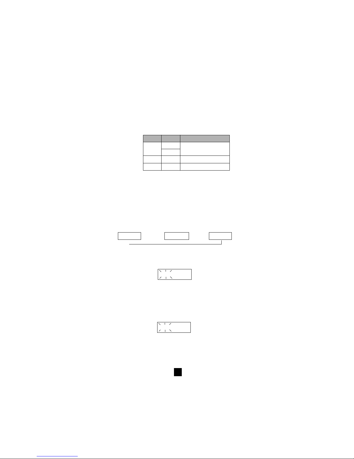
72
Die Messung des Isolationswiderstands an solchen Anlagen wird zunächst durch relativ hohe
Stromflüsse gestört: Ladeströme der Kapazitäten und dielektrische Verschiebungsströme, die erst mit
der Zeit abklingen. Um also den tatsächlich über die Isolierung abfließenden Leckstrom zu messen,
muss sich die Messung über eine bestimmte Zeit erstrecken, um den Einfluss dieser anfänglichen
Störströme auszuschließen.
Anschließend kann man aus dem Abklingverhalten den PI bzw. den DAR wie folgt berechnen:
PI = R 10 min / R 1 min (Messdauer :10 Minuten, Erfassung von 2 R-Werten)
DAR = R 1 min / R 30 s (Messdauer: 1 Minute, Erfassung von 2 R-Werten)
Die Güte der Isolierung lässt sich dann nach folgender Tabelle beurteilen:
DAR PI Zustand der Isolation
< 1,25 < 1 Ungenügend bzw.
< 2 gefährlich
< 1,6 < 4 In Ordnung
> 1,6 > 4 Sehr gut
■■
■■
■ Benutzung der Funktion R-DAR-PI
Während oder nach einer Messung lassen sich mit Taste R-DAR-PI die verschiedenen Werte anzeigen:
- DAR (Messdauer > 1 min)
- PI (Messdauer > 10 min)
- Kapazität in µF (erst nach Abschluss der Messung und Entladung des Messkreises).
- Isolationswiderstand in MΩ , GΩ oder TΩ
Automatische Messung des DAR oder des PI:
Wird die Taste R-DAR-PI vor Starten einer Messung gedrückt, erscheinen folgende Werte in der
Anzeige:
- - - - MΩ DAR - - - - PI - - - -
↑
Je nach Auswahl (DAR oder PI) läuft die Messung wie folgt ab:
a) DAR: START-Taste drücken → Symbol DAR blinkt, in der Anzeige erscheint „
- - - -
“ solange der
Verlustfaktor noch berechnet wird (Messdauer < 1 min).
Zum Beispiel: DAR
- - - -
Nach 1 Minute ist die Messung beendet und in der Hauptanzeige erscheint automatisch der für den
DAR berechnete Wert.
Die Taste R-DAR-PI kann während und nach der Isolationsmessung gedrückt werden, um die Ergebnisse
für R und DAR anzuzeigen, liefert aber keinen Wert für PI, da die Messung dafür zu kurz war.
b) PI: START-Taste drücken → Symbol PI blinkt, in der Anzeige erscheint „- - - -“ solange der
Polarisations-Index noch berechnet wird (Messdauer < 10 min).
Zum Beispiel: PI
- - - -
Nach 1 Minute ist die Messung beendet und in der Hauptanzeige erscheint automatisch der für
den PI berechnete Wert.
Während und nach der Messung erscheinen auf Druck der Taste R-DAR-PI der DAR-Wert (nach
1 Min.), der PI-Wert (nach 10 Min.) sowie der Isolationswiderstand.
Page 73
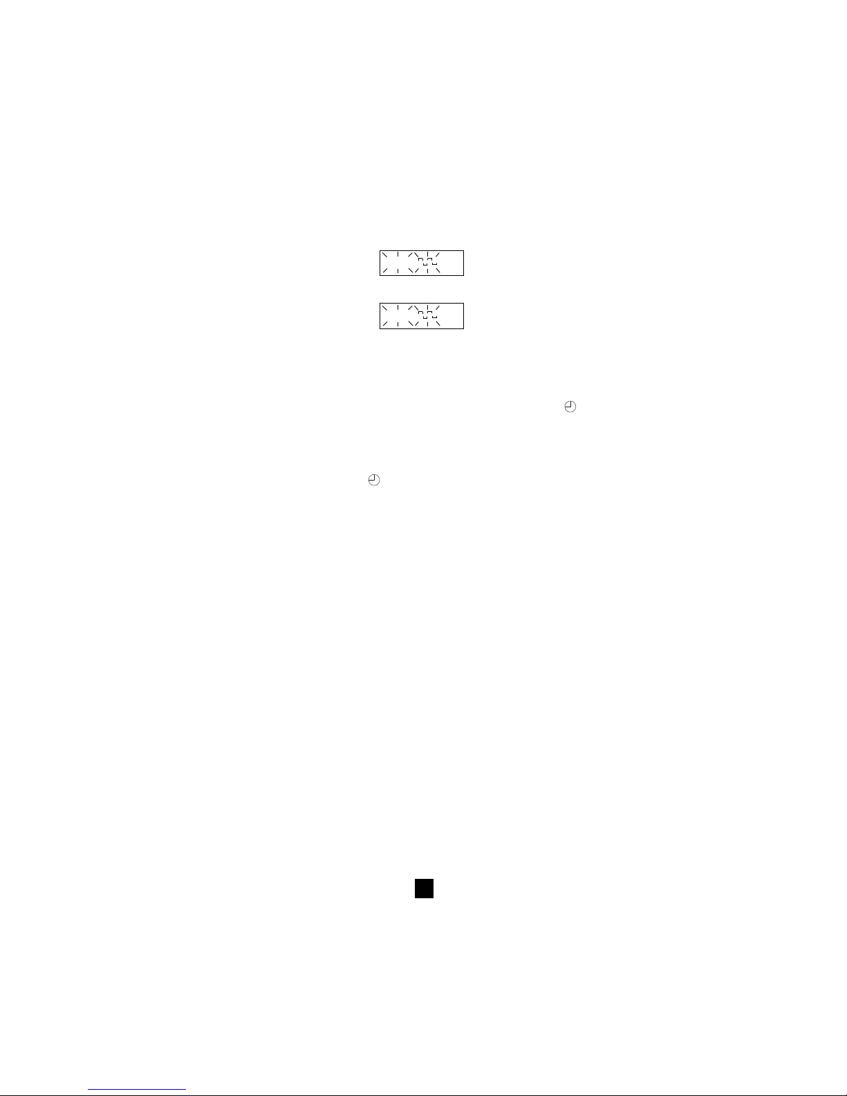
73
Hinweis: Falls während einer automatischen oder durch Tastendruck aufgerufenen Messung des DAR
oder des PI eine zu hohe externe Störspannung erkannt wird oder falls der Isolationswiderstand den
Messbereich übersteigt, wird die Berechnung des DAR bzw. des PI abgebrochen und in der Anzeige
erscheint:
DAR MΩ
bzw.
PI MΩ
Hinweis: Die Zeitvorgaben von 1 min bzw. 10 min für die PI-Berechnung sind im SET-UP-Menü
änderbar (siehe § 4.7) um das Gerät an evtl. Änderungen der Normen oder spezifische
Anwendungen anpassen zu können.
■■
■■
■ Zweitfunktion R (t)
Mit Taste R(t) lassen sich nach einer Messung mit „Programmierter Prüfdauer“
(siehe § 4.2) die
gespeicherten Zwischenergebnisse des Isolationswiderstands abrufen.
Das Zeitintervall für die Erfassung dieser Zwischenergebnisse ist im SET-UP-Menü einstellbar.
Diese Funktion ist auch im Modell C.A 6541 vorhanden, obwohl dieses Modell über keinen extra Speicher
und über keine Schnittstelle für die Datenausgabe zu einem PC verfügt.
Beim C.A 6541 können während einer
-Messung bis zu 20 Zwischenwerte in dem im SET-UP-Menü
eingestellten Zeitintervall erfasst werden (standardmäßig beträgt dieses Zeitintervall 30 s).
Falls es die im Prozessor verfügbare Speicherkapazität erlaubt, können auch mehr als 20 Werte
abgespeichert werden.
Beim C.A 6543 ist die Anzahl speicherbarer Zwischenwerte nur durch den verfügbaren Arbeitsspeicher begrenzt.
Nach Drücken der Taste R(t) schaltet das Gerät auf Anzeige der Zwischenwerte um:
- in der kleinen Anzeige erscheint die jeweilige Zeit (z.B. 00:30 wenn 30 s Intervall eingestellt wurden).
- in der großen Anzeige erscheint der zugehörige R-Wert.
In der kleinen Anzeige kann mit Taste V-TIME zwischen der zum R-Wert in der großen Anzeige gehörenden
Zeitangabe oder Spannungsangabe umgeschaltet werden.
Mit Taste
▲
▼
können alle während einer Messung erfassten Werte nacheinander durchgetastet werden.
Auf diese Art lassen sich problemlos Diagramme für R(t) und U(t) erstellen.
Mit dieser Funktion kann man direkt vor Ort, ohne PC- oder Druckeranschluss, eine Analyse der zeitlichen
Entwicklung von R(t) vornehmen.
Durch erneutes Drücken von Taste R(t) bzw. R-DAR-PI lässt sich diese Funktion wieder ausschalten.
4.4 Taste
✻✻
✻✻
✻ / ALARM
■■
■■
■ Hauptfunktion ✻
Mit dieser Taste lässt sich die Anzeigebeleuchtung ein- bzw. wieder ausschalten.
■■
■■
■ Zweitfunktion ALARM
Ein-/Ausschalten der ALARM-Funktion. Bei eingeschalteter Funktion erscheint das ALARM-Symbol in der Anzeige.
Wird in dieser Funktion während einer Messung die im SET-UP-Menü eingestellte obere bzw. untere
Alarmschwelle über- bzw. unterschritten, blinkt der ALARM-Schriftzug und der Summer gibt einen
ständigen Warnton ab (falls eingeschaltet).
Für jede Messfunktion lässt sich eine eigene obere bzw. untere Alarmschwelle eingeben. Diese
Schwellwerte bleiben auch nach Ausschalten des Geräts im Speicher erhalten.
Page 74

74
4.5 Taste ▼ / SMOOTH
■■
■■
■ Hauptfunktion
▼
Dient zur Auswahl des Parameters der geändert werden soll - der gewählte Parameter blinkt in der Anzeige.
Mit Taste
▲
▼
lässt sich der Parameter nun erhöhen/verringern (siehe § 4.6 unten).
■■
■■
■ Zweitfunktion SMOOTH
Schaltet eine digitale Filterfunktion für Isolationsmessungen ein: die Werte in der Anzeige werden
„geglättet“, d.h. unstabile Werte werden über einen bestimmten Zeitraum gemittelt. Die Messung ist
davon nicht betroffen.
Diese Funktion ist nützlich bei stark schwankenden Isolations-Messwerten, wie sie beispielsweise bei
hohen Kapazitäten im Messkreis auftreten.
4.6 Taste
▲
▼
Mit dieser Taste lassen sich die blinkend angezeigten Parameter verändern oder die R(t)-Werte abrufen
(siehe § 4.3).
Im Allgemeinen handelt es sich dabei um eine 2-stellige Zahl: Tag, Monat, Stunde, Minute, Sekunde,
OBJ-Nr., TEST-Nr.
Die Funktionen
▲▲
▲▲
▲ und
▼▼
▼▼
▼ sind dabei „durchlaufend“, d.h. so bald der obere/untere Grenzwert für die
Änderung erreicht ist, wird auf den nächsthöheren bzw. -niederen Grenzwert umgeschaltet.
■■
■■
■ Hauptfunktion
▲▲
▲▲
▲ : Durch kurzes Drücken wird die Zahl um eine Einheit erhöht (inkrementiert).
Bei längerem Drücken erhöht sich die Zahl mit größerer Schrittweite.
■■
■■
■ Zweitfunktion
▼▼
▼▼
▼ : Durch kurzes Drücken wird die Zahl um eine Einheit verringert (dekrementiert).
Bei längerem Drücken verringert sich die Zahl mit größerer Schrittweite.
Im Gegensatz zu allen anderen Funktionen muss für die Zweitfunktion ▼ nicht jedes Mal Taste
2nd
neu gedrückt werden. Die Zweitfunktion bleibt bei Taste ▼ so lange eingeschaltet und das Symbol
bleibt so lange in der Anzeige bis Taste
2nd
erneut oder eine andere Funktionstaste gedrückt wird.
4.7 SET-UP - Funktion (Gerätekonfiguration)
Das Konfigurationsmenü wird mit dem Drehschalter angewählt. In ihm lassen sich die Geräteparameter
an die jeweiligen Benutzerbedürfnisse anpassen.
Nachdem man den Drehschalter in Stellung SET-UP gestellt hat, laufen folgende Funktionen ab:
- während 1 s werden alle Segmente der LC-Anzeige aktiviert (Anzeigekontrolle)
- die Software-Versions-Nr. wird kurz angezeigt
- anschließend wird die Serien-Nr. des Geräts angezeigt
- in der kleinen Anzeige erscheint der Schriftzug PUSH und in der großen btn und fordert damit zum
Drücken einer Taste auf.
Durch Drücken der jeweiligen Funktionstaste erscheint in der SET-UP-Funktion der entsprechende
Parameter oder das Symbol in der Anzeige und kann vom Benutzer verändert werden:
- Die änderbaren Zahlenwerte oder Symbole blinken in der Anzeige. Zum Ändern werden die Tasten
▼
bzw.
▲
▼
benutzt
- Die geänderten Parameter werden sofort im nichtflüchtigen Speicher abgespeichert.
Die Tabelle auf der nächsten Seite gibt einen Überblick über die Tastenfunktionen im SET-UP-
Konfigurationsmenü, die zugehörigen Anzeigen (klein und groß) und den zulässigen Wertebereich der
Einstellungen.
Page 75

75
Zu ändernde
Taste
Anzeige
Parameter Groß Klein Symbol Wertebereich
Prüfdauer im Modus
15 : 00 min. sec
1 - 59 min
"Programmierte Prüfdauer"
1. und 2. Zeit zur
R-DAR-PI
2. Zeit 1. Zeit
min : sec
00 : 59
Berechnung von PI (10 min) (1 min) Prüfdauer
Messintervall für
Zwischenwerte bei R (t) 00 : 30 min : sec 5 s - 10 min
"Programmierter Prüfdauer"
Grenzwert bei MΩ−50 V ALARM 50 kΩ 50 V ALARM < 2 k-200 G und </>
Grenzwert bei MΩ−100 V ALARM (2 x) 100 kΩ 100 V ALARM < 4 k-400 G und </>
Grenzwert bei MΩ−250 V ALARM (3 x) 250 kΩ 250 V ALARM < 10 k-1 T und </>
Grenzwert bei MΩ−500 V ALARM (4 x) 500 kΩ 500 V ALARM < 20 k-2 T und </>
Grenzwert bei MΩ−1000 V ALARM (5 x) 1000 kΩ 1000 V ALARM < 40 k-4 T und </>
Grenzwert bei 400 kΩ
ALARM (6 x) 100 kΩ rES ALARM <
0,01-400 kΩ
(Widerstandsmessung) und </>
Grenzwert bei 40 Ω
ALARM (7 x) 2 Ω Cont ALARM <
0,01-40 Ω
(Durchgangsprüfung) und </>
Uhrzeit V-TIME 12 :55
Std. (0-24)
Min. (0-60)
Datum (Europa-Version) V-TIME (2 x) 17.03 1999 TT.MM.JJJJ
Version : USA, Europa V-TIME (3 x) USA/Euro
Speicher gesamt löschen MEM, anschl. MEM (2 s) cLr ALL MEM
Einzelne Werte im MEM, anschl.
▼
bzw.
▲
▼
cLr
OBJ : TEST MEM +
00...99
Speicher löschen und MEM (2 s) Nummer OBJ : TEST
Baudrate PRINT 9600 bAUd
300...9600
oder "parallel"
Summer ✻ On
Ein/Aus
Automatische Abschaltung ✻ (2 x) On Ein/Aus
Kompensation
✻ (3 x) - - - - On
W
0
Ein/Aus
anschl. ▲ und START (Wert nach START) bzw. 0,01-5 Ω
Standard-Konfiguration ✻ (4 x)
DFLt SEt
anschl. START
Isolationsmessung sperren ✻ (5 x) On 50 V Ein/Aus
Isolationsmessung sperren ✻ (6 x) On 100 V Ein/Aus
Isolationsmessung sperren ✻ (7 x) On 250 V Ein/Aus
Isolationsmessung sperren ✻ (8 x) On 500 V Ein/Aus
Isolationsmessung sperren ✻ (9 x) On 1000 V Ein/Aus
Die in dieser Tabelle in den Spalten „Anzeige / Groß“ bzw. „Anzeige / Klein“ aufgeführten Werte sind die
ab Werk standardmäßig vorgegebenen Werte. Wurden sie ungewollt verändert, lassen sich die
Originalwerte wiederherstellen (siehe § 4.7.4.).
Page 76

76
4.7.1 Speicher löschen
Im SET-UP-Menü auf Taste MEM drücken:
- das Symbol MEM blinkt
- in der kleinen Anzeige erscheint ALL
- in der großen Anzeige erscheint cLR .
Um den gesamten Speicher zu löschen Taste MEM erneut und für die Dauer von ca. 2 Sekunden
drücken:
- das Symbol MEM hört auf zu blinken
- in der großen Anzeige erscheint FrEE .
Um nur eine bestimmte OBJ:TEST -Nummer zu löschen:
- die gewünschte Speicherplatz-Nr. mit den Pfeiltasten ▼ und
▲
▼
auswählen
- cLr erscheint weiterhin in der großen Anzeige.
Taste MEM erneut und für die Dauer von ca. 2 Sekunden drücken:
- die gewählte OBJ:TEST -Nummer erscheint in der kleinen Anzeige
- in der großen Anzeige erscheint FrEE.
4.7.2 Datenübertragungsrate in Baud (RS 232)
Im SET-UP-Menü auf Taste PRINT drücken.
In der Hauptanzeige erscheint die derzeitige DÜ-Rate in Baud, d.h.: 300, 600, 1200, 2400, 4800, 9600
oder Parallel.
In der kleinen Anzeige erscheint baud. Mit Tasten
▲▲
▲▲
▲ und
▼ ▼
▼ ▼
▼ lässt sich die gewünschte DÜ-Rate einstellen.
Erscheint in der Anzeige der Schriftzug Parallel ist nicht die serielle RS 232-Schnittstelle sondern über
einen Zubehör-Adapter die schnellere Centronics-Schnittstelle für parallelen Druckeranschluss angewählt.
4.7.3 Kompensation der Messleitungen
Im SET-UP-Menü Taste ✻ 3-mal drücken:
Das Symbol
W
0
erscheint in der großen und der Schriftzug On erscheint in der kleinen Anzeige. Mit
Taste
▲
▼
lässt sich die Kompensation des Messleitungswiderstands bei Durchgangsmessungen
ausschalten (Anzeige wechselt auf: OFF).
Einspeichern des Messleitungswiderstands:
- die beiden Messleitungen verbinden und im SET-UP-Menü, Position
W
0
, Taste START drücken
- der Widerstand der Messleitungen erscheint in der großen Anzeige und wird abgespeichert.
Hinweise:
- Dieser Wert bleibt dauerhaft im Gerät abgespeichert.
- Der Messleitungswiderstand wird nur bei Durchgangsmessungen berücksichtigt.
- Die Funktion lässt sich jederzeit zu- oder abschalten, indem man mit Taste
▲
▼
zwischen On und OFF
in der kleinen Anzeige umschaltet.
- Der gespeicher te Wert erscheint auch bei abgeschalteter Kompensationsfunktion in der großen Anzeige,
wird jedoch nicht bei den Messungen berücksichtigt.
- Für die Messleitungskompensation können nur Werte zwischen 0 Ω und 5 Ω abgespeichert werden;
darüber erfolgt keine Einspeicherung.
Page 77

77
4.7.4 Standard-Konfiguration des Geräts
Im SET-UP-Menü Taste ✻ 4-mal drücken:
- in der kleinen Anzeige erscheint der blinkende Schriftzug SEt
- in der großen Anzeige erscheint DFLt (Default).
Taste START drücken, um die Ausgangskonfiguration des Geräts ab Werk wiederherzustellen (siehe Tabelle).
4.7.5 Sperren der Isolationsmessungen
Mit dieser Funktion können bestimmte Prüfspannungen für die Isolationsmessung gesperrt werden.
Damit lässt sich das Gerät z.B. gefahrlos auch von weniger geübten Personen benutzen (etwa in
Telefonanlagen usw...).
Im SET-UP-Menü ab dem 5. Druck auf Taste ✻ :
- Bei jedem weiteren Drücken der Taste ✻ erscheint eine Prüfspannung in der kleinen und On/OFF in
der großen Anzeige.
- Für jede der angezeigten Prüfspannungen kann nun mit Taste
▲
▼
zwischen On und OFF umgeschaltet
werden. Bei On ist die entsprechende Prüfspannung erlaubt, bei OFF ist sie für die Benutzung gesperrt.
5. GERÄTEBENUTZUNG
5.1 Ablauf einer Messung
■ Gerät einschalten indem man den Drehschalter auf die gewünschte Messfunktion stellt: MΩ, 40 Ω
oder 400 kΩ. Danach leuchten alle Segmente der LC-Anzeige kurz auf und die aktuelle
Betriebsspannung (Batterien oder Akku) erscheint in der Anzeige.
■ Messleitungen an die „+“ und „-“ Klemmen des Geräts und an die Messpunkte anschließen.
■ Die anliegende Spannung wird ständig gemessen und in der kleinen Anzeige angezeigt.
Ist diese Fremdspannung höher als die in den §§ 5.2, 5.3 und 5.4 angegebenen Werte, ist keine
Messung möglich.
■ Durch Drücken der Taste START/STOP wird die Messung gestartet.
■ Erneutes Drücken von START/STOP beendet die Messung. Der letzte Messwert bleibt in der Anzeige
bis zum Start der nächsten Messung oder bis der Drehschalter verstellt wird.
Wenn während einer Messung eine Fremdspannung > 25 VAC oder ≥35 VDC festgestellt wird, bricht das
Gerät die laufende Messung ab, der gemessene Spannungswert erscheint in der kleinen Anzeige und
das Warn-Symbol blinkt.
Hinweis: Bei jeder Messung sind bestimmte Sonderfunktionen zuschaltbar (siehe § 4).
5.2 Isolationsmessung (siehe auch § 3.2)
In dieser Funktion misst das Gerät Isolationswiderstände im Bereich von 2 kΩ bis 4 TΩ, je nach gewählter
Prüfspannung: 50 - 100 - 250 - 500 - 1000 V.
■ Mit dem Drehschalter die gewünschte Prüfspannung einstellen: MΩ-50 V, MΩ-100 V, MΩ-250 V, MΩ-
500 V, MΩ-1000 V.
■ Megohmmeter an den zu prüfenden Stromkreis anschließen. Liegt an den Prüfklemmen eine
Fremdspannung von mehr als 8 V in M
ΩΩ
ΩΩ
Ω-50 V bzw. von 16 V in M
ΩΩ
ΩΩ
Ω-100 V bzw. von 50 V in allen
anderen Bereichen an, ist eine Messung nicht möglich.
Page 78

78
■ Messung mit Taste START beginnen und Ergebnisse ablesen.
Die einzelnen Ergebnisse können in der Hauptanzeige mit Taste R-DAR-PI (siehe § 4.3) oder in der
kleinen Anzeige mit Taste V-TIME „durchgeblättert“ werden (siehe § 4.2).
Bei „Programmierter Prüfdauer“ lassen sich die mit dem im SET-UP eingestellten Zeitintervall erfassten
Zwischenergebnisse mit Taste R (t) in die Anzeige rufen. Diese Zwischenergebnisse sind bis zum Start
einer neuen Messung oder bis zum Umschalten der Messfunktion mit dem Drehschalter jederzeit
abrufbar (siehe § 4.3).
Bei der Messung hoher Isolationswiderstände (> 1 G
ΩΩ
ΩΩ
Ω) empfiehlt es sich, den Prüfling auch über die
Schutzklemme „G“ zu verbinden, um den Einfluss von Kriechströmen auf Oberflächen auszuschalten.
Dieser „Guard“-Anschluss ist an einer Oberfläche des Prüflings anzubringen, auf der es zu Kriechströmen
durch Verschmutzung, Staub oder Feuchtigkeit kommen kann. Bei einem Stromkabel oder an einem
Transformator ist dies beispielsweise die isolierende Oberfläche zwischen zwei Messpunkten. Dafür
sollten in jedem Fall Krokodilklemmen benutzt werden, vom Aufsetzen von Prüfspitzen mit der Hand
wird dringend abgeraten, um Leckstromabflüsse oder kapazitive Effekte zu vermeiden (siehe § 11).
Nach Abschluss einer Isolationsmessung entlädt das Megohmmeter den Prüfkreis automatisch
über einen eingebauten Widerstand.
5.3 Durchgangsmessung (siehe auch § 3.3)
In dieser Funktion beträgt der Messstrom > 200 mA zwischen 0 und 20 Ω bzw. > 140 mA zwischen 20
und 40 Ω. Die Messung dient z.B. zur Prüfung der Niederohmigkeit von PE-Schutzleitern.
Der Messbereich wird vom Gerät automatisch bis auf 40 Ω hochgeschaltet, die Auflösung beträgt
maximal 0,01 Ω.
■ Drehschalter auf Stellung 40 Ω drehen
■ Gerät an den zu prüfenden Stromkreis anschließen
■ Liegt eine Fremdspannung > 3 V vor, ist eine Messung nicht möglich
■ Mit Taste START Messung starten und Ergebnis ablesen.
Hinweis:
Der Widerstand der Messleitungen lässt sich dabei durch Kompensation ausschalten (siehe § 4.7.3).
Die Tasten R-DAR-PI und V-TIME sind bei dieser Messart wirkungslos.
Bei Durchgangsmessungen findet kein automatischer Polaritätswechsel statt.
5.4 Widerstandsmessung (siehe auch § 3.3)
In dieser Messart begrenzt das Gerät den Messstrom auf 6 mA. Der Messbereich wird vom Gerät
automatisch bis auf 400 kΩ hochgeschaltet, die Auflösung beträgt maximal 0,01 Ω.
■ Drehschalter auf Stellung 400 Ω drehen
■ Gerät an den zu prüfenden Stromkreis anschließen
■ Liegt eine Fremdspannung > 3 V vor, ist eine Messung nicht möglich
■ Mit Taste START Messung starten und Ergebnis ablesen.
Während der Messung erscheint in der kleinen Anzeige der Spannungsabfall an den Klemmen (nützlich bei
Messungen an Bauelementen mit mehreren PN-Übergängen: Thyristoren, Hochspannungs-Dioden usw...).
Die Leerlaufspannung entspricht der Versorgungsspannung des Geräts (Batterie beim C.A 6541 bzw.
Akku beim C.A 6543).
Hinweis: Die Tasten R-DAR-PI und V-TIME sind in dieser Messart wirkungslos.
5.5 Kapazitätsmessung
Eine Kapazitätsmessung wird automatisch bei jeder Isolationsmessung durchgeführt. Nach Abschluss
der Messung und Entladung des Prüfkreises kann der Wert mit Taste R-DAR-PI in die Anzeige gerufen
werden.
!
!
Page 79

79
6. SPEICHER / RS 232 (nur C.A 6543)
6.1 Eigenschaften der RS 232-Schnittstelle
■ Die Datenübertragungsrate über die serielle RS 232-Schnittstelle lässt sich auf 300, 600, 1200,
2400, 4800, 9600 Baud einstellen, oder auf „Parallel“ (d.h. Centronics) mit dem Zubehör-Adapter
für parallelen Druckeranschluss.
Die Einstellung wird im SET-UP-Menü vorgenommen (siehe § 4.7).
■ Datenformat: 8 Datenbits, 1 Stopbit, ohne Parität, Xon/Xoff-Protokoll
■ Serielle Druckerschnittstelle
Buchse,9-polig zumC.A 6543
Stecker,9-polig zumseriellen Drucker
2
2
3
3
5
5
Draufsicht
Draufsicht
■ Anschluss an einen PC oder an einen Parallel-Drucker
9-poliger Stecker zumPC
9-poliger Stecker
zum C.A 6543
➂
➁
25-poliger Stecker zum PC
oder zum Seriell/Parallel-Adapter
➀
25-poliger Stecker
Notwendige Verbindungen DB9
➔➔
➔➔
➔ B25 (
➀➀
➀➀
➀
→→
→→
→
➁➁
➁➁
➁)
■■
■■
■ Adapter DB25
➔➔
➔➔
➔ DB9 (
➁➁
➁➁
➁
→→
→→
→
➂➂
➂➂
➂) :
(Nullmodemkabel) :
1 ➔ 8 6 ➔ 20 2 ➔ 3
2 ➔ 2 7 ➔ 5 3 ➔ 2
3 ➔ 3 8 ➔ 4 7 ➔ 5
4 ➔ 6 9 ➔ 22
5 ➔ 7
6.2 Messwerte abspeichern bzw. aufrufen (Taste MEM/MR)
6.2.1 Hauptfunktion MEM (Werte abspeichern)
Mit der Speicherfunktion lassen sich Messergebnisse im Arbeitsspeicher des Geräts abspeichern.
Die Ergebnisse werden in Speicherplätzen abgelegt, die durch eine Prüflings-Nummer (OBJ) und eine
Prüfungs-Nr (TEST) gekennzeichnet sind.
Page 80

80
Ein „Prüfling“ oder ein „Objekt“ stellt einen Speicherbereich dar, in den bis zu 99 Prüfungen eingetragen
werden können. Ein solcher Prüfling kann z.B. eine Maschine oder eine Anlage sein, an der man
verschiedene Messungen vornehmen möchte. Das können Isolations-, Widerstands- oder
Durchgangsmessungen sein.
1. Bei Drücken der Taste MEM blinkt das Symbol MEM und in der kleinen Anzeige erscheint die erste freie
OBJ:TEST-Nr, z.B. 02 : 01. In der großen Anzeige erscheint der Schriftzug FrEE (Speicherplatz frei).
Die OBJ-Nr. ist dabei dieselbe wie bei der letzen Messung (d.h. gleicher Prüfling), die TEST-Nr. wird
automatisch um 1 erhöht (nächste Messung).
Mit den Tasten
▼
und
▲
▼
lassen sich die Nummern in OBJ:TEST nach Bedarf ändern.
Falls dabei ein bereits belegter Speicherplatz angewählt wird, erscheint die Meldung OCC (belegt) in
der großen Anzeige.
Gibt man bei OBJ eine neue Prüflings-Nr. ein, wird die TEST-Nr automatisch auf 01 gesetzt.
2. Beim zweiten Drücken der Taste MEM werden die aktuellen Messergebnisse im gewählten
Speicherplatz abgelegt (falls der Platz belegt war, wird er überschrieben). MEM blinkt nun nicht mehr
und die Ergebnisse werden zusammen mit den zugehörigen Daten (R, U, t) abgespeichert.
Wurde vor dem zweiten Drücken von MEM eine andere Funktionstaste oder der Drehschalter
betätigt, verlässt das Gerät den Speichermodus ohne die Werte abzuspeichern.
3. Wurde eine Messung mit „Programmierter Prüfdauer“ vorgenommen, so stehen auch
Zwischenergebnisse zur Verfügung (siehe § 4.3). Diese Werte werden automatisch unter derselben
OBJ:TEST -Nr. wie die Hauptmessung abgespeichert.
■■
■■
■ Abschätzung der Speicherkapazität
Gesamt-Speicherkapazität: 128 KByte
Interne Speicherverwaltung: 8 KByte
Verfügbarer Speicher: 120 KByte
Der Speicherbedarf für ein Isolations-Messergebnis beträgt ca. 80 Byte.
Bei „Programmierter Prüfdauer“
, werden pro Zwischenwert jeweils 10 Byte mehr benötigt.
Eine Widerstands- oder eine Durchgangsmessung belegen 26 Byte.
Insgesamt können also ca. 1500 Isolationsmessungen oder ca. 4000 Widerstands- oder
Durchgangsmessungen im Gerät gespeichert werden.
■■
■■
■ Verfügbarer Speicherplatz
Bei Abspeichern eines Ergebnisses zeigt das Gerät automatisch die verfügbare Speicherkapazität an.
Beim ersten Drücken von Taste MEM erscheint eine neue, freie OBJ:TEST-Nr. und der Bargraph zeigt
an, wie viel Speicherplatz noch zu Verfügung steht:
- wenn der Speicher noch ganz frei ist, sind alle Segmente dunkel
- wenn der Speicher belegt ist, blinkt der linke Pfeil am Bargraph
- nach Abspeichern eines Messwerts erlischt die Bargraph-Anzeige wieder.
Ein Bargraph-Segment entspricht dabei etwa 50 Speicherplätzen.
6.2.2 Zweitfunktion MR
Mit der Speicheraufruf-Funktion MR können gespeicherte Werte jederzeit und unabhängig von der
Drehschalterstellung in die Anzeige gerufen werden.
■ Nach Drücken der Taste erscheint das Symbol MR ständig in der Anzeige.
In der kleinen Anzeige erscheint die letzte OBJ:TEST-Nr. die verwendet wurde, z.B. 02:11.
Bei der Nr. 02:11 blinkt die „11“ über dem Schriftzug „TEST“ und das bekannte Verfahren zum
Ändern der Zahlen mit Tasten
▼
und
▲
▼
kann nun verwendet werden.
Page 81

81
Bei Anwahl einer neuen OBJ-Nr. wird die TEST-Nr. automatisch auf die höchste abgespeicherte
TEST-Nr. gesetzt.
In diesem Stadium können sämtliche Ergebnisse im Speicher mit den Tasten
▼
und
▲
▼
aufgerufen
werden: die zur betreffenden OBJ- und TEST-Nr. gehörenden Werte erscheinen nacheinander in der
großen Anzeige und man kann sie mit der Taste R-DAR-PI durchblättern.
■ Mit Taste V-TIME kann für jedes Ergebnis in der kleinen Anzeige zwischen Datum / Uhrzeit / U /
OBJ:TEST-Nr. umgeschaltet werden.
Gehören zu dem mit OBJ:TEST angewählten Speicherplatz Zwischenwerte (Messung mit
„Programmierter Prüfdauer“
lassen sich diese mit Taste R (t) in die große Anzeige rufen. In der
kleinen Anzeige erscheint dann die zugehörige Zeit in der Form min : sec (für den 1. Zwischenwert)
und das Symbol
blinkt. Mit Taste
▲
▼
lassen sich nacheinander die weiteren Zwischenwerte aufrufen.
Um die Funktion R (t) zu beenden und wieder zur normalen Speicheabruf-Funktion (OBJ :
TEST) zurückzukehren, Tasten R (t) oder R-DAR-PI erneut drücken.
!
Um die Speicherabruf-Funktion MR zu beenden, erneut Taste MR drücken oder den Drehschalter
verstellen.
Page 82

82
6.3 Ausdruck von Messwerten (Taste PRINT/PRINT MEM) (nur C.A 6543)
Bei Benutzung eines seriellen Druckers im SET-UP-Menü die geeignete Datenausgaberate (zwischen
300 und 9600 Baud) auswählen und Drucker auf das vom Gerät benutzte Ausgabeformat einstellen
(siehe § 6.1).
Bei Anschluss eines Parallel-Druckers muss der Druckerausgang im SET-UP-Menü auf „Parallel“ gestellt
werden und der Zubehör-Adapter ist zu verwenden (Adapter zwischen das mitgelieferte Druckerkabel
und das Centronics-Anschlusskabel des Druckers einfügen).
Für den Ausdruck stehen zwei Möglichkeiten zur Verfügung:
- sofortiger Ausdruck des aktuellen Messwerts (PRINT)
- Ausdruck der gespeicherten Messwerte (PRINT memory)
Wenn die Datenausgabe über den Drucker fehlerfrei funktioniert, blinkt das COM-Symbol in der Anzeige.
Bei Problemen leuchtet das COM-Symbol ständig in der LC-Anzeige.
6.3.1 Sofort-Ausdruck des aktuellen Messwerts (Taste PRINT)
Nach einer Messung oder bei Aufruf der gespeicherten Werte mit MR können mit Taste PRINT die
entsprechenden Ergebnisse ausgedruckt werden.
Bei Drücken der Taste werden die Werte wie folgt ausgedruckt:
- als 1 Gruppe von Werten: U/R/DAR/PI/Datum/Uhrzeit im Falle einer normalen Messung
- mit den Zwischenwerten R(t) wenn die „Programmierter Prüfdauer“ gewählt wurde.
Um den Ausdruck zu stoppen, braucht man lediglich den Drehschalter zu verstellen.
Je nach Messfunktion erhält man einen Ausdruck nach dem folgenden Muster:
■■
■■
■ Isolationsmessung
CHAUVIN ARNOUX C.A 6543
Geräte-Nr.: 000 001
ISOLATIONSWIDERSTANDSMESSUNG
OBJEKT : 01 TEST : 01 (wird nur im MR-Modus gedruckt)
Beschreibung: ..............................................
.....................................................................
Datum: ....................................... 31.03.1998
Uhrzeit Beginn: .................................. 14h55
Prüfdauer: ............................ 15 min. 30 sec
Temperatur: ................................ °C .........°F
Rel. Luftfeuchte: ........................................ %
Prüfspannung: ..................................1000 V
Isolationswiderstand (R): ........... 385 GOhm
DAR (R 1'/R 30"): ................................ 1,234
PI (R 10'/R 1"): .................................... 2,345
Bemerkungen: .............................................
.....................................................................
Datum der nächsten Prüfung: ....... /..../.......
Bei einer Messung mit „Programmierter Prüfdauer“ werden auch die Zwischenergebnisse ausgedruckt:
Zeit Widerstand Spannung
00 : 30 35,94 GOhm 1005 V
01 : 00 42,00 GOhm 1005 V
01 : 30 43,50 GOhm 1005 V
usw.... Am Ende des Ausdrucks erscheint eine Zeile für die Unterschrift des Bedieners.
!
Page 83

83
■■
■■
■ Durchgangs- oder Widerstandsmessung
CHAUVIN ARNOUX C.A 6543
Geräte-Nr.: 000 001
DURCHGANGS- bzw. WIDERSTANDSMESSUNG
OBJEKT : 01 TEST : 01 (wird nur im MR-Modus gedruckt)
Beschreibung: ..............................................
.....................................................................
Datum: ....................................... 31.03.1998
Uhrzeit Beginn: ................................ 14 h 55
Prüfstrom: .................................... > 200 mA
Kompensation Messleitungen: ......... 0,12 Ω
Spannungsabfall: .................................0,9 V
Durchgang/Widerstand: .................... 0,45 Ω
Bemerkungen: .............................................
.....................................................................
.....................................................................
Datum der nächsten Prüfung: ....... /..../.......
Am Ende des Ausdrucks erscheint eine Zeile für die Unterschrift des Bedieners.
6.3.2 Ausdruck gespeicherter Daten (Taste PRINT MEM)
Mit dieser Funktion werden die im Gerät gespeicherten Daten ausgedruckt.
In der kleinen Anzeige erscheint 01 :01 als die erste auszudruckende OBJ:TEST-Nr. (Druckbeginn) und
in der großen Anzeige erscheint die zuletzt gespeicherte OBJ:TEST-Nr (Druckende) z. B.: 12 : 06 .
Die Zahl „01“ über dem Schriftzug „OBJ“ blinkt. Mit Tasten
▼
und
▲
▼
können nun die Speicherplatz-
Zahlen für Duckbeginn und Druckende nach Bedarf geändert werden.
Funktion verlassen ohne Ausdruck: Stellung des Drehschalters verändern.
Ausdruck starten: Taste PRINT erneut drücken.
Druck abbrechen: Stellung des Drehschalters verändern.
Bei jedem gespeicherten Datensatz werden nur die Hauptergebnisse ausgedruckt.
Beispiel:
CHAUVIN ARNOUX C.A 6543
Geräte-Nr.: 000 001
DURCHGANGSMESSUNG
OBJEKT : 01 TEST : 01
Datum: ....................................... 31.03.1998
Uhrzeit Beginn: ................................. 14h 55
Durchgang: ....................................... 0,45 Ω
DURCHGANGSMESSUNG
OBJEKT : 01 TEST : 02
Datum: ....................................... 31.03.1998
Uhrzeit Beginn: .................................. 15h00
Durchgang: ....................................... 0,91 Ω
ISOLATIONSWIDERSTANDSMESSUNG
OBJEKT : 01 TEST : 03
Datum : ...................................... 31.03.1998
Page 84
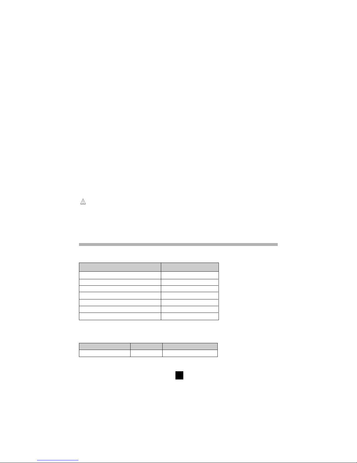
84
Uhrzeit Beginn: ................................. 15h 10
Prüfdauer: .............................15 min 30 sec
Temperatur: ............................... °C .........°F
Rel. Luftfeuchte: ....................................... %
Prüfspannung: .................................. 1000 V
Isolationswiderstand (RI): .............. 385 GΩ
DAR (RI 1’/30“): .................................. 1,234
PI (RI 10’/RI1’): ................................... 2,345
Bemerkungen: .............................................
.....................................................................
.....................................................................
Am Ende des Ausdrucks erscheint eine Zeile für die Unterschrift des Bedieners.
6.4 Drucken mit dem Seriell/Parallel-Adapter
1. Das RS232 Null-Modemkabel an das C.A 6543 anschließen.
2. An dieses Kabel den Adapter anschließen und Druckerkabel an den Adapter anschließen.
3. Drucker einschalten.
4. C.A 6543 einschalten.
5. Zum sofortigen Ausdrucken des aktuellen (nicht eingespeicherten) Messwerts Taste PRINT drücken.
6. Zum Ausdrucken der eingespeicherten Messwerte Taste «PRINT MEM» drücken.
!
ACHTUNG: Dieser Adapter wurde ausschließlich für die Benutzung mit dem C.A 6543
entwickelt und darf nicht für andere Zwecke verwendet werden.
7. TECHNISCHE DATEN
7.1 Bezugsbedingungen
Einflussgrößen Bezugswerte
Temperatur 23°C +/- 3K
Rel. Luftfeuchte 45 bis 55 %
Versorgungsspannung 9 bis 12 V
Frequenzbereich DC und 15,3...65 Hz
Parallel-Kapazität zum Widerstand 0 µF
Elektrisches Feld ohne
Magnetisches Feld < 40 A/m
7.2 Technische Daten der Messfunktionen
7.2.1 Spannung
Messumfang Auflösung Frequenzbereich
1... ... 1000 V 1 V DC / 16 ... 420 Hz
Page 85
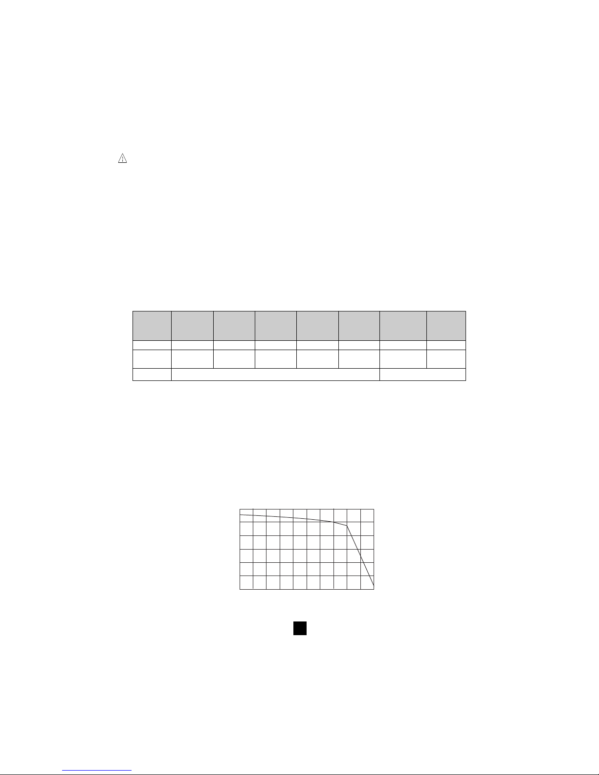
85
■■
■■
■ Genauigkeit: ±1% Anz. ±3 Digit, AC-Spannung sinusförmig oder DC
■■
■■
■ Eingangswiderstand: ca. 750 kΩ
Achtung: Gerät ist gemäß EN 61010-1 eingestuft in Cat III 600 V. Es darf nicht an Spannungen von
mehr als 600 V gegenüber Erde angeschlossen werden.
7.2.2 Isolationswiderstand
■■
■■
■ Messverfahren: Spannungs- und Strommessungen gemäß der Norm EN 61557-2
■■
■■
■ Nenn-Ausgangsspannungen: 50, 100, 250, 500, 1000 VDC
■■
■■
■ Leerlaufspannung: ≤ 1,1 x Un ± 5 V (50, 100, 250, 500, 1000 V)
■■
■■
■ Nennstrom: > 1 mADC bei Nennspannung
■■
■■
■ Kurzschlussstrom: < 6 mADC
■■
■■
■ Max. zul. Spannung: Ueff max. = 1200 V AC und DC bei 10 Sekunden in den Bereichen "+" und "-"
660 V AC und DC in den Bereichen "G" und "-" oder "G" und "+"
■■
■■
■ Messbereiche:
50 V : 2 kΩ... 200 GΩ
100 V : 4 kΩ... 400 GΩ
250 V : 10 kΩ... 1 TΩ
500 V : 20 kΩ... 2 TΩ
1000 V : 40 kΩ... 4 TΩ
Bereich 2 ... 999 kΩ
4,00..39,99 40,0..399,9
400...999 MΩ
4,00..39,99 40,0..399,9
400...999 GΩ
1,000..3,999
MΩ MΩ
1,000..3,999
GΩ GΩ 1,000...3,999
MΩ
GΩ TΩ
Auflösung 1 kΩ 10 kΩ 100 kΩ 1 MΩ 10 MΩ 100 MΩ 1 GΩ
Spannung 50, 100, 250 50, 100, 250 50, 100, 250, 50, 100, 250, 50, 100, 250, 50, 100, 250, 250 V,
500, 1000 V 500, 1000 V 500, 1000 V 500, 1000 V 500, 1000 V 500, 1000 V 500, 1000 V
Genauigkeit ±(5% Anz. +3 Digit) ±(15% Anz. +10 Digit)
Messung der DC-Spannung nach einer Isolationsprüfung
■■
■■
■ DC-Spannungsbereich: 25...1000 V
■■
■■
■ Auflösung: 0,5% UDC
■■
■■
■ Genauigkeit: ±1% Anz. ±3 Digit
■■
■■
■ Spannungsverlauf hängt von der Last ab
Kapazitätsmessung (nach Entladung des Prüflings)
■■
■■
■ Messbereich: 0,005...4,999 µF
■■
■■
■ Auflösung: 1 nF
■■
■■
■ Genauigkeit: ±(10% + 1 Digit)
Typischer Verlauf der Prüfspannungen in Abhängigkeit von der Last
Prüfspannung 50 V
0
100
90
80
70
60
Résistance en kW
Tension de sortie (V)
50
40
30
20
10
0
10
20
30
40
50
60
!
Page 86
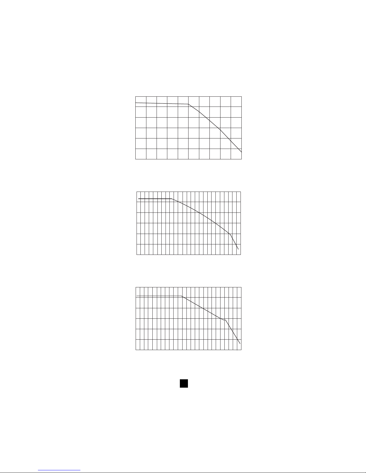
86
Prüfspannung 100 V
0
100
90
80
70
60
Widerstand (kW)
Ausgangsspannung(V)
50
40
30
20
10
0
20
40
60
80
100
120
Prüfspannung 250 V
0
250
200
150
100
50
0
50
100
150
200
250
300
Widerstand (kW)
Ausgangsspannung(V)
Prüfspannung 500 V
0
500
400
300
200
100
0
100
200
300
400
500
600
Widerstand (kW)
Ausgangsspannung(V)
Page 87
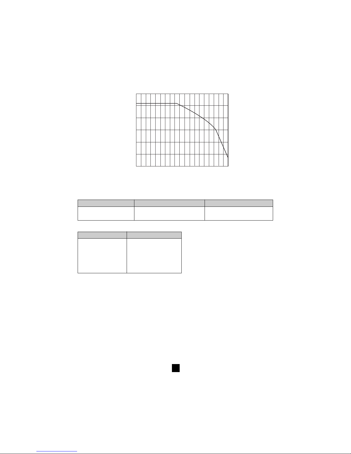
87
Prüfspannung 1000 V
0
1000
800
600
400
200
50
200
400
600
800
1000
1200
Widerstand (kW)
Ausgangsspannung (V)
■■
■■
■ Typische Stabilisierungszeit des Messwerts je nach geprüfter Isolation
In den folgenden Zeiten sind das Laden evtl. vorhandener Kapazitäten, die Bereichsumschaltung und
das Einregeln der Prüfspannung bereits enthalten.
Last ohne Kapazität: Last mit 1 µF Kapazität:
Isolationswert von 1 MΩ 7 s 7s
Isolationswert von 500 GΩ 17 s 20 s
■■
■■
■ Entladezeit des Prüfkreises auf max. 25 V (über eingebauten 750 k
Ω−Ω−
Ω−Ω−
Ω−Widerstand)
Prüfspannung Entladezeit
1000 V 2,8 s
500 V 2,2 s
250 V 1,7 s
100 V 1 s
50 V 0,5 s
■■
■■
■ Wertebereich für DAR und PI : 0,000 bis 9,999
Genauigkeit: ±5%
7.2.3 Durchgangsmessung
■■
■■
■ Messverfahren: Spannungs- und Strommessungen gemäß der Norm EN 61557-4
■■
■■
■ Leerlaufspannung: 12,4 VDC max. (< 15 V mit externer Stromversorgung)
■■
■■
■ Kurzschlussstrom: > 200 mADC
■■
■■
■ Max. zul. Spannung: 1200 V AC und DC bei 10 Sekunden in den Bereichen "+" und "-"
660 V AC und DC in den Bereichen "G" und "-" oder "G" und "+"
■■
■■
■ Kompensation der Messleitungen:
R∆ wird bei kurzgeschlossenen Messleitungen im SET-UP-Menü gemessen (siehe § 4.7). Dieser
Wert wird gespeichert und von allen Durchgangsmessungen abgezogen. Die Kompensation ist auf
max. 5 Ω begrenzt.
R angezeigt = R gemessen - R∆
■■
■■
■ Messbereich für R DURCHGANG: 0,01 bis 39,99 Ω
■■
■■
■ Auflösung: 0,01 Ω
Page 88
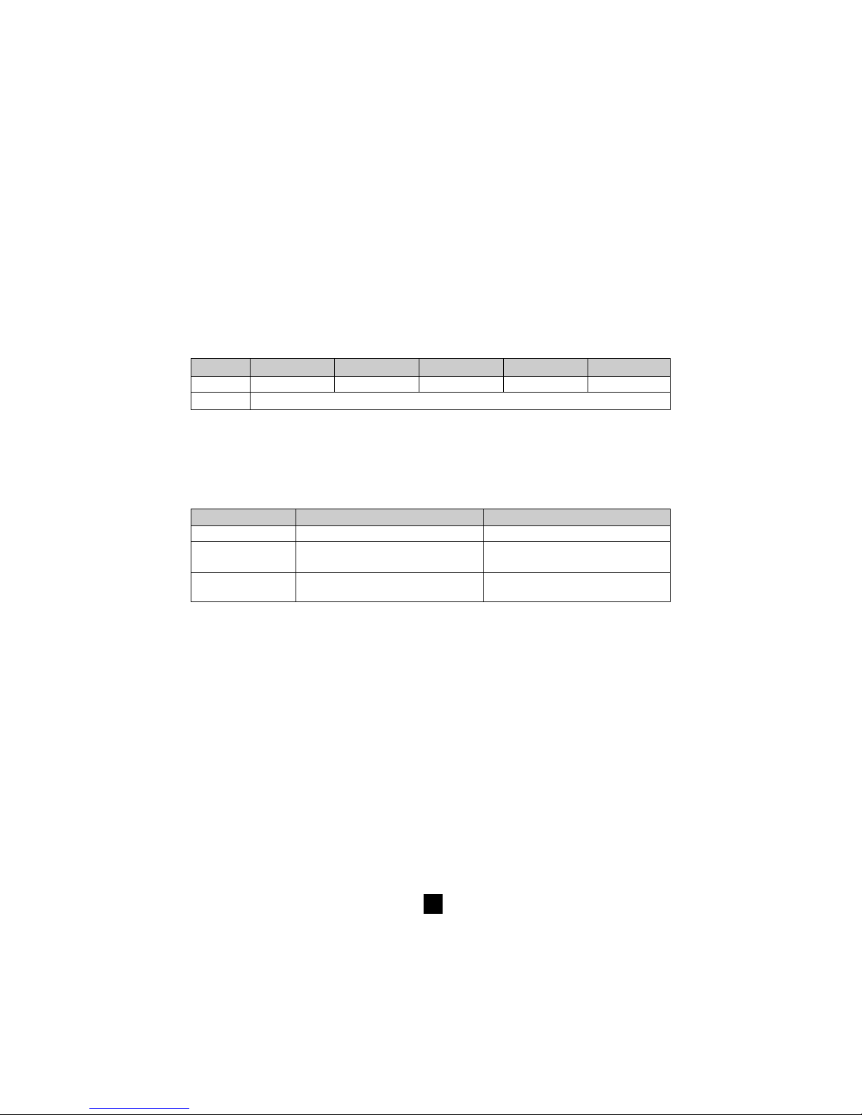
88
■■
■■
■ Messstrom: > 200 mA von 0,01 bis 20,00 Ω und > 140 mA von 20,01 bis 39,99 Ω
■■
■■
■ Genauigkeit: ±3% Anz. ±4 Digit
■■
■■
■ Max. zul. Induktivität: 5 H ohne Schaden für das Gerät
■■
■■
■ Max. zul. Serientaktspannung: 3 VAC/DC, darüber ist keine Messung mehr möglich
7.2.4 Widerstandsmessung
■■
■■
■ Messverfahren: Spannungs-/Strommessung
■■
■■
■ Leerlaufspannung: 12,4 VDC max. (< 15 V mit externer Stromversorgung)
■■
■■
■ Kurzschlussstrom: < 6 mADC
■■
■■
■ Max. zul. Spannung: 1200 V AC und DC bei 10 Sekunden in den Bereichen "+" und "-"
660 V AC und DC in den Bereichen "G" und "-" oder "G" und "+"
■■
■■
■ Max. zul. Serientaktspannung: 3 VAC/DC, darüber ist keine Messung mehr möglich
Bereich 0,01..39,99 Ω 40,0..399,9 Ω 0,400..3,999 kΩ 4,00..39,99 kΩ 40,0..399,9 kΩ
Auflösung 0,01 Ω 0,1 Ω 1 Ω 10 Ω 100 Ω
Genauigkeit ±3 % Anz. ±3 Digit
7.3 Stromversorgung
■■
■■
■ Die Stromversorgung wird gewährleistet durch:
- 8 Batterien 1,5 V LR 14 (C.A 6541)
- wiederaufladbaren NiMh-Akku (C.A 6543)
mit Ladegerät für Anschluss an 85 bis 256 V / 50-60 Hz (Elektrische Sicherheit : 256 V Cat. III)
Modell: C.A 6541 C.A 6543
Messart: Mittlere Betriebsdauer Mittlere Betriebsdauer
Isolation 21 000 Messungen à 5 s mit 20 s Pause 5 000 Messungen à 5 s mit 20 s Pause
bei Nennlast * (1) bei Nennlast * (2)
Durchgang 16 000 Messungen à 5 s mit 20 s Pause 4 000 Messungen à 5 s mit 20 s Pause
bei Nennlast * bei Nennlast *
* Nennlast: 1000 V/1 mA
(1) Bei Annahme von täglich 5 PI-Messungen zu je 10 Minuten reicht ein Batteriesatz für 67 Tage (d.h. 10 Wochen oder
2,5 Monate)
(2) Bei Annahme von täglich 5 PI-Messungen zu je 10 Minuten reicht eine Akku-Ladung für 16 Tage (d.h. 2,5 Wochen
oder 0,5 Monate)
■■
■■
■ Nachladedauer (C.A 6543)
4,5 Std. auf 100% der Akku-Kapazität (Max. Ladedauer: 6 Std.)
0,5 Std. auf 10% der Akku-Kapazität (Betriebsdauer: ca. 1 Tag)
7.4 Klimabedingungen
■■
■■
■ Betriebsbereich:
-10° bis +40°C, während der Akku-Ladung
-10° bis +55°C, für Messungen
20% bis 80 % rel. Luftfeuchte
■■
■■
■ Nennbereich:
0° bis +35°C
■■
■■
■ Lagerbereich:
-40° bis +70°C
10% bis 90 % rel. Luftfeuchte
Page 89
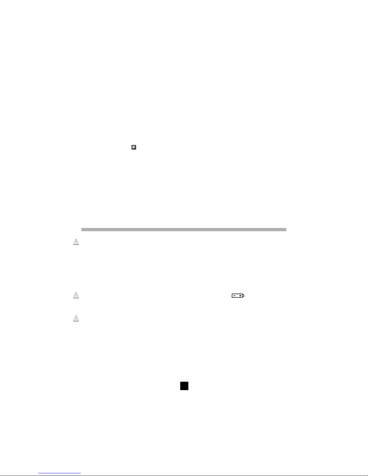
89
■■
■■
■ Einfluss der Temperatur auf die Messgenauigkeit (alle Messfunktionen)
±0,15 % pro K
■■
■■
■ Meereshöhe: < 2000 m
7.5 Mechanische Daten
■ Außenabmessungen Gehäuse (L x B x H) : 240 x 185 x 110 mm
■ Gewicht: ca. 3,4 kg
7.6 Normeneinhaltung
■ Elektrische Sicherheit gem.: EN 61010-1, EN 61557
■ Doppelt schutzisoliert:
■ Verschmutzungsgrad: 2
■ Anlagenkategorie: III
■ Max. zul. Spannung gegenüber Erde: 600 V
7.6.1. Elektromagnetische Verträglichkeit
■ Störaussendung und Störimmunität im industriellen Umfeld gemäß EN 61326-1
7.6.2. Mechanischer Schutz
Schutzart IP 53 gem. DIN EN 60529
IK 04 gem. DIN EN 50102
8. WARTUNG / INSTANDHALTUNG
Verwenden Sie für Reparaturen ausschließlich die angegebenen Ersatzteile. Der Hersteller haftet
keinesfalls für Unfälle oder Schäden, die nach Reparaturen außerhalb seines Kundendienstnetzes
oder durch nicht von ihm zugelassene Reparaturbetriebe entstanden sind.
8.1. Wartung
8.1.1. Ersetzen der Batterien (C.A 6541)
Bei Einschalten des Geräts erscheint für 2 s die aktuelle Batteriespannung in der kleinen Anzeige
während in der großen Anzeige „bAt“ erscheint. Diese Batterieprüfung wird mit einer der Messfunktion
entsprechenden internen Last durchgeführt.
Vor Durchführung einer Messung darauf achten, dass das Batteriesymbol
nicht in der Anzeige
blinkt (bei Einschalten des Geräts erscheint für 2 s die aktuelle Batteriespannung in der kleinen Anzeige).
Bei ungenügender Spannung die Batterien sofort auswechseln, dabei vor Öffnen des Geräts auf die
Sicherheit achten.
An die Eingangsklemmen dürfen keine Kabel angeschlossen sein und der Drehschalter muss
auf OFF stehen bevor das Gerät zum Batteriewechsel geöffnet wird.
Nur 1,5 V Alkali-Batterien des Typs LR14 verwenden.
Zum Öffnen des Gerätes die vier unverlierbaren Schrauben unter dem Gerät lockern. Sobald sie leer
drehen, das Gerät auf eine Abstellfläche stellen, auf die Schrauben drücken und die Vorderseite der
Platine herausnehmen.
Das Gerät umdrehen, um die Platine ganz herauszunehmen. Nach der Lockerung der Schrauben am
Batteriengehäuse ist der Zugang zu diesen auf der Rückseite der Platine möglich. Achtung: den
Dichtungsring beim Herausnehmen und Wiedereinsetzen der Platine nicht beschädigen.
!
!
!
Page 90

90
8.1.2 Nachladen des Akkus (C.A 6543)
Sobald das blinkende Symbol
erscheint, muss der eingebaute Akku nachgeladen werden.
Dazu das Gerät über die Steckdose ➅ an das Netz anschließen. Die Nachladung des Akkus beginnt
automatisch:
■ Wenn bAt in der kleinen und CHrG ständig in der großen Anzeige erscheint, erfolgt die normale
Schnellladung
■ Wenn bAt in der kleinen und CHrG blinkend in der großen Anzeige erscheint, erfolgt eine langsame
Ladung (sobald es die Temperatur erlaubt, wird automatisch auf Schnellladung umgeschaltet)
■ Wenn bAt in der kleinen und FULL in der großen Anzeige erscheint, ist die Ladung abgeschlossen.
Wenn der Akku bei Einschalten des Geräts eine Spannung > 8 V aufweist, ist die normale Benutzung
des Geräts möglich.
Der Batterienwechsel hat durch Manumesure oder durch einen Spezialisten der Firma CHAUVIN
ARNOUX zu erfolgen.
Bei einem Wechsel des Akkus gehen alle gespeicherten Daten verloren. Bei Drücken der Taste MEM/
MR zeigt dann das Gerät die Fehlermeldung „OFF“ an. Um die Speicherfunktion MEM/MR wieder einwandfrei
nutzen zu können, muss im SET-UP-Menü der Speicher komplett gelöscht werden (siehe § 4.7.1).
8.1.3 Ersetzen der Sicherungen
Falls beim Einschalten oder bei Durchgangsmessungen die blinkende Meldung FUS HI oder FUSE -G-
erscheint, ist die entsprechende Sicherung defekt und muss ersetzt werden. Dabei vor Öffnen des
Geräts auf die Sicherheit achten (siehe § 8.1.1 für das Öffnen des Geräts).
An die Eingangsklemmen dürfen keine Kabel angeschlossen sein und der Drehschalter muss
auf OFF stehen bevor das Gerät geöffnet wird.
Sicherungstypen (auf dem Etikett des Sicherungsfachs angegeben):
- Sicherung F2 am + Eingang (FUS HI) : T 2,5 A - 1,2 kV - 8 x 50 mm - 15 kA
- Sicherung F1 am G Eingang (FUSE G) : F 0,1 A - 660 V - 6,3 x 32 mm - 20 kA
8.1.4 Reinigung des Geräts
Dazu muss das Gerät von jeglicher Stromquelle getrennt sein.
Benutzen Sie einen weichen, leicht mit Seifenwasser getränkten Lappen. Mit einem feuchten Lappen
nachwischen und das Gerät anschließend mit einem trockenen Lappen oder einem Luftstrahl trocknen.
Zum reinigen keinesfalls Spiritus, Lösungsmittel oder Kohlenwasserstoffe (Benzin) verwenden.
8.1.5 Nachkalibrierung
Wird das Gerät über einen längeren Zeitraum nicht benutzt (mehr als zwei Monate), nehmen Sie die
Batterien heraus und lagern Sie sie getrennt (C.A 6541).
8.1.6 Meßgerät-Überprüfung
Wie auch bei anderen Mess- oder Prüfgeräten ist eine regelmäßige Geräteüberprüfung
erforderlich.
Es wird mindestens eine einmal jährlich durchgeführte Überprüfung dieses Gerätes empfohlen. Für
Überprüfung und Kalibrierung wenden Sie sich bitte an unsere zugelassenen Messlabors (Auskunft und
Adressen auf Anfrage), bzw. an die Chauvin Arnoux Niederlassung oder den Händler in Ihrem Land.
■■
■■
■ Wartung
Senden Sie das Gerät bei Reparaturen innerhalb und außerhalb der Garantie an die Chauvin Arnoux
Niederlassung oder Ihren Händler zurück.
9. GARANTIE
Unsere Garantie erstreckt sich auf eine Dauer von zwölf Monaten ab dem Zeitpunkt der Bereitstellung
des Geräts (Auszug aus unseren allg. Verkaufsbedingungen. Erhältlich auf Anfrage).
!!!
!
!
!
Page 91

91
10. BESTELLANGABEN
Megohmmeter C.A 6541 ..................................................................................................... P01138901
Lieferung in der Tragetasche mit:
2 Sicherheitsmessleitungen (rot + blau), 1,5 m, gerade Stecker
1 Sicherheitsleitung „Guard“ (schwarz), 1,5 m
3 Krokodilklemmen (rot, blau, schwarz)
1 Prüfspitze (schwarz)
8 Batterien LR14
5 Kurzanleitungen (jeweils 1 pro Sprache)
und 1 Bedienungsanleitung (in 5 Sprachen)
Megohmmeter C.A 6543 ..................................................................................................... P01138902
Lieferung in der Tragetasche mit:
1 Kabel DB9F-DB9F
1 Adapter DB9M-DB9M
2 Sicherheitsmessleitungen (rot + blau), 1,5 m, gerade Stecker
1 Sicherheitsleitung „Guard“ (schwarz), 1,5 m
3 Krokodilklemmen (rot, blau, schwarz)
1 Prüfspitze (schwarz)
1 Netzkabel, 2 m
5 Kurzanleitungen (jeweils 1 pro Sprache)
und 1 Bedienungsanleitung (in 5 Sprachen)
Zubehör:
■ Prüfspitze mit Fernbedienung .......................................................................................... P01101935
■ 2 Prüfspitzen (rot + schwarz) ........................................................................................P01295458Z
■ 3 Sicherheitsmessleitungen (rot + blau + schwarz), 3 m ................................................ P01295170
■ PC-Software (C.A 6543)................................................................................................ P01101938A
■ Serieller Drucker (C.A 6543) ............................................................................................ P01102903
■ Adapter Seriell/Parallel (C.A 6543) ................................................................................... P01101941
Ersatzteile:
■ 3 Sicherheitsmessleitungen (rot + blau + schwarz), 1,5 m, gerade Stecker ................. P01295171
■ 4 Krokodilklemmen (rot, blau, schwarz, grün)................................................................. P01101801
■ Tagetasche Nr. 6 für Zubehör .......................................................................................... P01298051
■ Sicherung F 2,5 A - 1200 V - 8 x 50 mm - 15 kA (5 Stck.) ............................................. P01297071
■ Sicherung F 0,1 A - 660 V - 6,3 x 32 mm - 20 kA (10 Stck.) .......................................... P01297072
■ Akkumulator 9,6 V - 2,4 AH - NiMh (C.A 6543) ............................................................... P01296021
■ RS 232 PC-Abschlusskabel DB 9F - DB 25F x2 (C.A 6543) ......................................... P01295172
■ RS 232 Druckeranschlusskabel DB 9F - DB 9M N°01 (C.A 6543) ............................... P01295173
■ Netzanschlusskabel 2P (C.A 6543)................................................................................. P01295174
Page 92

92
Italiano
Significato del simbolo
!
ATTENZIONE ! Consultare il libretto d’istruzioni prima di utilizzare lo strumento.
Nelle presenti istruzioni d’uso, le istruzioni precedute da questo simbolo, se non completamente
rispettate o realizzate, possono causare un incidente all’operatore o danneggiare l’apparecchio e le
installazioni.
Significato del simbolo
Questo apparecchio è protetto da un isolamento doppio o un isolamento rinforzato. L’apparecchio
non necessita il collegamento alla presa di terra di protezione per assicurare la sicurezza elettrica.
Significato del simbolo
ATTENZIONE ! Rischio di folgorazione.
La tensione delle parti contrassegnate da questo simbolo è suscettibile di essere pericolosa ≥120 V DC.
Per motivi di sicurezza, questo simbolo si accende sul display LCD quando una tensione è generata.
Avete acquistato uno megaohmmetro C.A. 6541 o C.A. 6543e vi ringraziamo della vostra fiducia.
Per ottenere le migliori prestazioni dal vostro strumento :
■ leggete attentamente queste istruzioni
■ rispettate le precauzioni d’uso citate
!
PRECAUZIONI D’USO
!
■ Rispettare le condizioni d’uso: temperatura, umidità, altitudine, livello di inquinamento e luogo di
utilizzo
■ Questo strumento può essere utilizzato su impianti di categoria III per tensioni che non eccedono i
600 V rispetto alla terra. La categoria III risponde alle esigenze di affidabilità e disponibilità severe
corrispondenti agli usi permanenti su impianti fissi industriali (vedi EN 61010)
■ Utilizzare accessori di collegamento di categoria di sovratensione e tensione superiore o uguale a
quella dell’apparecchio di misura (600 V Cat III). Utilizzare solo accessori conformi alle norme di
sicurezza (EN 61010-2-032).
■ Rispettare il valore e il tipo di fusibile (vedi § 8.1.3) a pena di deteriorare l’apparecchio e di annullare
la garanzia.
■ Mettere il commutatore in posizione OFF quando l’apparecchio è inattivo.
■ Verificare che nessuna boccola sia collegata e che il commutatore sia posizionato su OFF prima di
aprire l’apparecchio.
■ Le operazioni di riparazione o verifica metrologica devono essere effettuate da personale competente
e autorizzato.
■ Il CA 6543 non consente di effettuare delle misure simultaneamente alla ricarica delle batterie.
■ Caricarsi della battería è indispensabile prima delle prove metrologiche.
Page 93

93
SOMMARIO
1. PRESENTAZIONE ......................................................................................................................... 94
1.1 I megaohmmetri ..................................................................................................................... 94
1.2 Gli accessori .......................................................................................................................... 94
2. DESCRIZIONE ............................................................................................................................... 96
2.1 Contenitore ............................................................................................................................. 96
2.2 Display ................................................................................................................................... 97
3. FUNZIONI DI MISURA .................................................................................................................. 99
3.1 Tensione AC / DC .................................................................................................................. 99
3.2 Misura d’isolamento ............................................................................................................... 99
3.3 Continuità (40 Ω
) / resistenza (400 kΩ) ...................................................................... 100
4. FUNZIONI SPECIALI .................................................................................................................. 101
4.1 Tasto
2nd
............................................................................................................................. 101
4.2 Tasto V-TIME /
................................................................................................................ 101
4.3 Tasto R-DAR-PI / R (t) ........................................................................................................ 101
4.4 Tasto ✻ / ALARM ................................................................................................................ 103
4.5 Tasto
▼
/ SMOOTH ........................................................................................................... 104
4.6 Tasto
▲
▼
............................................................................................................................... 104
4.7 Funzione SET-UP (configurazione dell’apparecchio)) ....................................................... 104
5. UTILIZZO ..................................................................................................................................... 107
5.1 Svolgimento delle misure ..................................................................................................... 107
5.2 Misura d’isolamento ............................................................................................................. 107
5.3 Misura della continuità ......................................................................................................... 108
5.4 Misura della continuità ......................................................................................................... 108
5.5 Misura di capacità ................................................................................................................ 108
6. MEMORIA / RS 232 (C.A 6543) .................................................................................................. 109
6.1 Caratteristiche della RS 232 ................................................................................................ 109
6.2 Registrazione / rilettura dei valori memorizzati) ................................................................. 109
6.3 Stampa dei valori misurati (tasto PRINT/PRINT MEM) (C.A 6543) .................................. 112
6.4 Stampa con l’adattatore seriale-parallelo ............................................................................ 114
7. CARATTERISTICHE ................................................................................................................... 114
7.1 Condizioni di riferimento ...................................................................................................... 114
7.2 Caratteristiche per funzione ................................................................................................ 114
7.3 Alimentazione ....................................................................................................................... 118
7.4 Condizioni ambientali ........................................................................................................... 118
7.7 Caratteristiche costruttive ................................................................................................... 119
7.8 Conformità alle norme internazionali ................................................................................... 119
8. MANUTENZIONE ........................................................................................................................ 119
8.1. Manutenzione ....................................................................................................................... 119
9. GARANZIA .................................................................................................................................. 120
10. PER ORDINARE .......................................................................................................................... 121
11. ALLEGATO .................................................................................................................................. 152
11.1 Frontali ................................................................................................................................. 152
11.2. Esempi applicativi ................................................................................................................ 153
11.3 Accessori ............................................................................................................................. 156
Page 94

94
1. PRESENTAZIONE
1.1 I megaohmmetri
I megaohmmetri C.A. 6541 e C.A. 6543 sono apparecchi portatili, montati in un contenitore da cantiere
robusto con coperchio chiuso, funzionanti a pile (C.A 6541), batteria o rete alternata (C.A 6543).
Essi consentono le misure:
■ di tensione,
■ d’isolamento,
■ di continuità,
■ di resistenza,
■ e di capacità.
Questi megaohmmetri contribuiscono alla sicurezza degli impianti e dei materiali elettrici.
Il loro funzionamento è assicurato tramite microprocessore per l’acquisizione, l’elaborazione, la
memorizzazione, la visualizzazione delle misure e la stampa dei risultati (C.A. 6543).
Offrono numerosi vantaggi come:
■ il filtro digitale delle misure d’isolamento,
■ l’avviamento delle misure tramite una sonda di comando remotizzata,
■ la misura di tensione automatica in tutte le funzioni,
■ la detezione automatica della presenza di una tensione esterna AC o DC sulle boccole, prima o
durante le misure, che disabilita o interrompe le misure, in qualsiasi funzione,
■ la programmazione delle soglie in ogni funzione, per attivare gli allarmi tramite segnale acustico,
■ il contaminuti per il controllo della durata delle misure,
■ la protezione dell’apparecchio tramite fusibile, con detenzione fusibile difettoso,
■ la sicurezza dell’operatore grazie allo scaricamento automatico dell’alta tensione residua del
dispositivo testato,
■ l’arresto automatico dell’apparecchio per risparmiare le pile (C.A 6541) o la batteria (C.A 6543)
■ l’indicazione di usura delle pile (C.A 6541) o lo stato di carica delle batterie (C.A 6543),
■ un display LCD retroilluminato, di grandi dimensioni, con molteplici annunciatori che offrono
all’utilizzatore un grande comfort di lettura.
Il C.A. 6543 possiede le seguenti funzioni supplementari:
■ Batteria integrata ricaricabile da rete alternata
■ Funzionamento diretto da rete alternata
■ Memoria (128 KB), orologio tempo reale e interfaccia seriale
■ Pilotaggio dell’apparecchio a partire da un PC (col software MEGOHM VIEW optional)
■ Stampa in modalità RS 232 o Centronics
1.2 Gli accessori
■■
■■
■ Sonda di comando deportata (optional, vedi § 11.3)
Questa sonda va collegata ad un connettore specifico.
Consente di effettuare tutte le misure grazie al pulsante giallo il cui funzionamento corrisponde al pulsante
START/STOP dell’apparecchio.
Il pulsante posto sul retro della sonda consente di illuminare il punto della misura (illuminazione a circa
500 lux). una funzione molto utile poiché le misure d’isolamento avvengono su impianti disattivati, quindi
senza luce.
Page 95

95
■■
■■
■ Software PC “Megohm View” (optional per il C.A 6543)
Il software PC consente:
- di recuperare i dati in memoria, tracciare la curva dell’evoluzione d’isolamento in base ai tempi di
applicazione della tensione di prova R (t),
- di stampare protocolli di prova personalizzati in base alle esigenze dell’utente,
- è di creare file testuali per potere utilizzare i programmi di calcolo elettronico (Excel™, …),
- di configurare e pilotare integralmente l’apparecchio via RS 232.
La configurazione minima raccomandata è un PC dotato di processore 486DX100.
■■
■■
■ Stampante seriale (optional per il C.A 6543)
Questa stampante di dimensioni ridotte consente di stampare direttamente in cantiere i risultati di misura,
memorizzati o meno.
■■
■■
■ Adattatore seriale-parallelo
L’adattatore RS232/Centronics disponibile optional consente di convertire l’interfaccia seriale (RS232)
in interfaccia stampante parallela (Centronics) e questo consente una stampa diretta di tutte le misure
su stampanti da ufficio in formato A4, senza ricorrere ad un computer personale.
Page 96

96
2. DESCRIZIONE
2.1 Contenitore
Consultare i prospetti di presentazione degli apparecchi al § 11 Allegato, posto alla fine del presente
libretto di istruzioni.
2.1.1 C.A 6541 e C.A 6543
➀ 3 boccole di sicurezza Ø 4 mm contrassegnate: “ + ”, “ G “ et “ - “
A fianco della boccola “-“, 2 contatti supplementari consentono di collegare la sonda di comando
deportata (connettore a 3 punti).
➁ Commutatore rotante 9 posizioni:
§ Off : spegnimento dell’apparecchio
§ MΩ - 50 V : misura d’isolamento fino a 200 GΩ
§ MΩ -100 V : misura d’isolamento fino a 400 GΩ
§ MΩ -250 V : misura d’isolamento fino a 1 TΩ
§ MΩ -500 V : misura d’isolamento fino a 2 TΩ
§ MΩ -1000 V : misura d’isolamento fino a 4 TΩ
§ 400 KΩ : misura di resistenza
§ 40 Ω : misura di continuità
§ SET-UP : regolazione della configurazione dell’apparecchio
➂ 1 tasto giallo START / STOP: inizio / fine della misura
➃ 6 tasti (C.A 6541) o 8 tasti (C.A 6543) in elastomero dotati ciascuno di una funzione principale e di
una funzione secondaria:
2nd
Selezione della funzione secondaria (in giallo corsivo sotto ad ogni tasto)
Funzione primaria: prima delle misure d’isolamento, scelta del tipo di misura desiderata
R-DAR-PI
fra misura normale, rapporto di assorbimento dielettrico (DAR) o indice di polarizzazione
(PI). Dopo avere effettuato le misure, visualizzazione di R, DAR, PI e capacità (µF).
R (t)
Funzione secondaria: visualizzazione dei valori intermedi di resistenza d’isolamento,
tensione di prova e datazione, in seguito a prova di durata programmata (è possibile
utilizzare anche i tasti V-TIME e
▲
▼
).
V-TIME
Funzione primaria: In isolamento, visualizzazione del tempo trascorso dall’inizio della
misura, poi della tensione esatta generata. In Resistenza o Continuità, questo tasto è
inattivo. In modalità MR (richiamo memoria), visualizzazione della data e dell’ora della
misura memorizzata, della tensione esatta di prova e del numero di OBJ: TEST.
Funzione secondaria: attivazione/disattivazione della modalità “prova a durata
programmata”
✻
Funzione primaria: accensione / spegnimento della retroilluminazione del display
ALARM
Funzione secondaria: attivazione / disattivazione degli allarmi programmati nel SET-UP
▼
Funzione primaria: sceglie un parametro da modificare
SMOOTH
Funzione secondaria: ON/OFF del livellamento della misura d’isolamento
Page 97
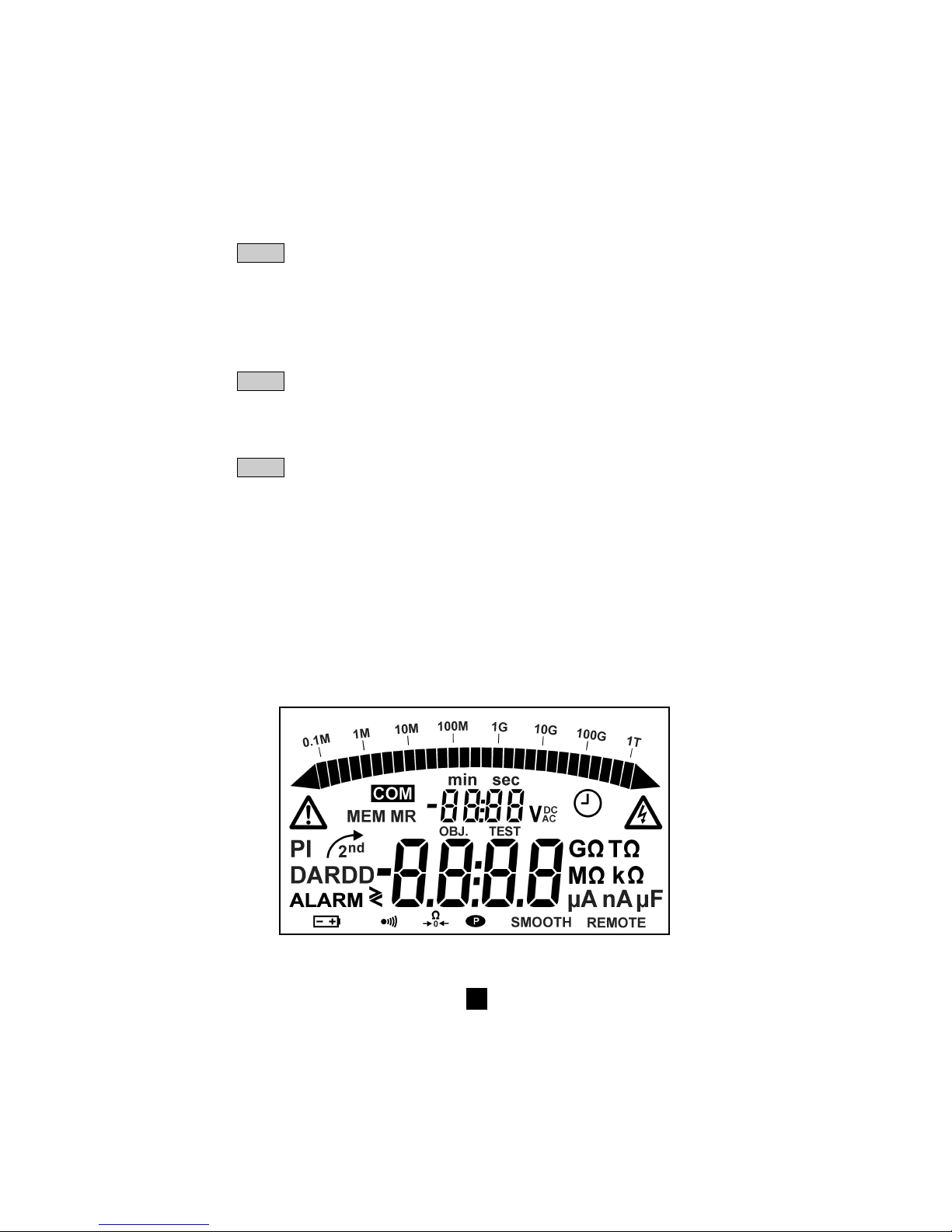
97
▲ Funzione primaria: incrementa il parametro lampeggiante visualizzato. Spostamento
nella lista delle misure intermedie d’isolamento, nella funzione R(t).
▼
Funzione secondaria: decrementa il parametro lampeggiante visualizzato.
Spostamento nella lista delle misure intermedie d’isolamento, nella funzione R(t).
Se premendo i tasti ▲ e ▼ è mantenuto, la velocità di variazione dei parametri è rapida.
■■
■■
■ Sul C.A 6543 unicamente
MEM Funzione primaria: memorizzazione dei valori misurati
MR Funzione secondaria: richiamo dei dati in memoria (questa funzione non dipende
dalla posizione del commutatore)
PRINT Funzione primaria: stampa immediata del risultato di misura
PRINT Funzione secondaria: stampa del contenuto della memoria
MEM
➄ Display a cristalli liquidi retroilluminati
2.1.2 solo C.A 6543
➅ Presa per collegamento a rete alternata (funzionamento diretto da reti AC/ricarica della batteria)
➆ Presa maschio INTERFACCIA seriale RS 232 (9 pin) per collegamento a un PC o una stampante
Nota: Il compartimento delle pile (C.A 6541) o batterie (C.A 6543) si trova all’interno del contenitore.
2.2 Display
Page 98
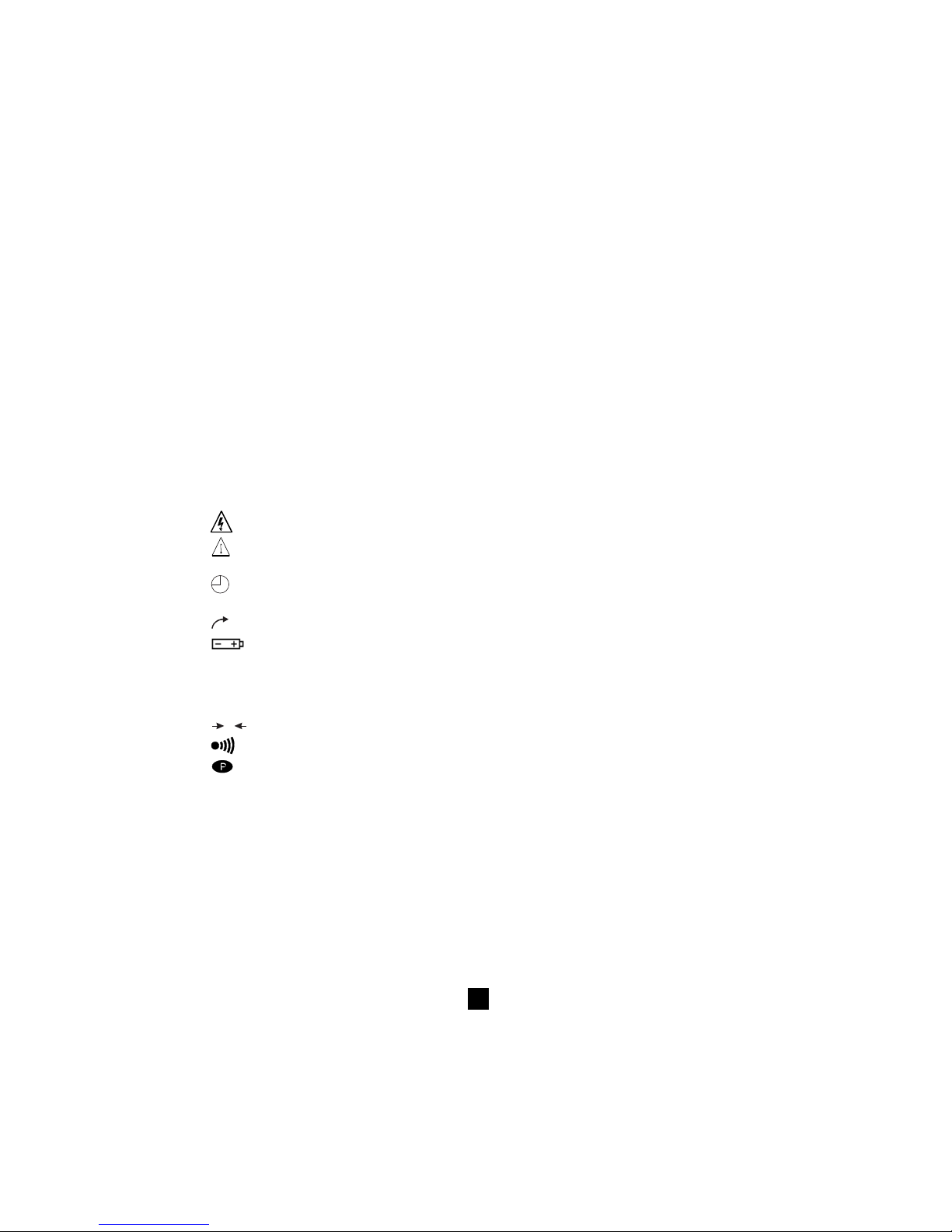
98
2.2.1 Display digitale
Il display digitale principale indica i valori in funzione misura d’isolamento (resistenza, DAR e PI, capacità)
e in funzione misura di continuità e resistenza.
Il piccolo display digitale indica la tensione misurata o applicata dallo strumento.
Durante la misura d’isolamento, il tempo trascorso o la tensione d’uscita viene visualizzata.
Dopo la registrazione di un gruppo di dati (C.A 6543), il piccolo display indica inoltre l’ora e la data in
modalità MR (Richiamo Memoria). Serve anche per indicare l’indirizzo di memoria col numero OBJ.
TEST (vedi § 2.2.2. Simboli).
2.2.2 Bargraph
Il bargraph è attivo in misura d’isolamento (0.1 MΩ a 1 TΩ). Serve anche ad indicare la carica della
batteria e lo spazio memoria, un segmento che rappresenta circa 100 gruppi di valori memorizzabili.
2.2.3 Simboli
MEM/MR Indica le operazioni di memorizzazione (MEM) o di lettura di memoria (MR) (C.A 6543)
OBJ: TEST Indirizzo memoria (C.A 6543) : il numero viene visualizzato sopra, sul piccolo display digitale.
COM Lampeggia sul display quando i dati vengono trasmessi all’interfaccia seriale (C.A 6543) o
rimane visualizzato in permanenza se c’è un problema di trasmissione.
DAR/PI Indica la modalità scelta prima della misura d’isolamento o i risultati delle misure.
Tensione generata pericolosa, U > 120 V.
!
Tensione esterna presente, simbolo attivato in seguito alla premuta sul tasto START, se
U > 25 VAC ±3 V o > 35 VDC
Attivazione della modalità “Prova a durata programmata” o in posizione SET-UP del
commutatore, regolazione dell’orologio (C.A 6543)
2nd
Indica che la funzione secondaria di un tasto sta per essere utilizzata
Lampeggia se la tensione delle pile (C.A 6541) o la batteria (C.A 6543) è debole. Le pile
devono essere sostituite o la batteria ricaricata (vedi § 8 Manutenzione)
La tensione viene visualizzata sul piccolo display digitale per 2 secondi all’accensione
dell’apparecchio. La visualizzazione principale indica “bat”. Questo test avviene con modalità
interna su un carico corrispondente alla misura funzionale.
W
0
Segnala che la compensazione dei cavi è attiva.
L’avvisatore sonoro (cicalino) è attivo
Indica che la funzione di arresto automatico è disattivata
SMOOTH Spianamento della visualizzazione delle misure d’isolamento
REMOTE Controllo a distanza via interfaccia (C.A 6543). In questa modalità, tutti i tasti e il commutatore
rotativo sono inattivi, ad eccezione dello spegnimento strumento.
FUSE HI Lampeggia se il fusibile dell’ingresso “ + “ è difettoso.
FUSE -G- Lampeggia se il fusibile dell’ingresso “ G “ è difettoso.
Page 99

99
3. FUNZIONI DI MISURA
3.1 Tensione AC / DC
Qualsiasi rotazione del commutatore in posizione d’isolamento, resistenza o continuità pone l’apparecchio
in misura di tensione AC / DC automatica. La tensione è misurata in permanenza e indicata sul piccolo
display.
Il lancio delle misure è inibito se una tensione esterna è presente sulle boccole, prima di premere
START / STOP. Analogamente, se viene rilevata una tensione parassita durante le misure, queste
s’interrompono automaticamente e la tensione viene indicata.
3.2 Misura d’isolamento
Alla rotazione del commutatore su una delle posizioni MΩ, il display principale indica “ ——MΩ ” e il
piccolo display indica la tensione presente sulle boccole + e – dell’apparecchio.
Se la tensione esterna presente sulle boccole dell’apparecchio è superiore alle soglie indicate
dalla tabella in basso, premendo un volta il tasto giallo START / STOP non si avvia una misura
d’isolamento bensì si induce l’emissione di un segnale sonoro discontinuo (bip, bip, bip…) e il
lampeggiamento del simbolo per 2 secondi, poi l’apparecchio torna in misura di tensione automatica.
Se la tensione esterna presente sulle boccole dell’apparecchio è inferiore alle soglie indicate in
basso, la misura d’isolamento è autorizzata:
Prove Tensione maxi autorizzata
con prima della misura
50 V 8 V
100 V 16 V
250 V 50 V
500 V 50 V
1000 V 50 V
Premendo il tasto START si attiva immediatamente la misura. Il valore di misura viene visualizzato sul
display digitale principale e sul bargraph. Un segnale sonoro intermittente ogni 10 secondi segnala che
la misura è in corso.
Se la tensione generata è potenzialmente pericolosa (> 120 V) , appare il simbolo
.
Se, durante le misure d’isolamento, viene rilevata una tensione esterna > 25 VAC ±3 V o 35VDC, la
misura s’interrompe finché la tensione è applicata allo strumento. Il simbolo
!
lampeggia e il
valore della tensione è indicato nel piccolo display digitale.
Se le misure sono instabili, è possibile utilizzare la funzione SMOOTH (vedi § 4.2).
Premendo il tasto V-TIME durante la misura consente di visualizzare alternatamente sul piccolo display
la durata della misura e la tensione esatta generata (vedi § 4.3).
L’arresto della misura è provocato da un’ulteriore premuta del tasto STOP.
Dopo l’arresto della misura, il risultato principale rimane visualizzato.
È possibile fare scorrere tutti gli altri risultati disponibili sul display principale utilizzando il tasto R-DAR-
PI. Questo tasto può essere utilizzato anche prima di attivare la misura (vedi § 4.3).
Se è stata scelta la modalità “Prova a durata programmata” , il tasto R (t) consente di accedere a tutte
le misure intermedie memorizzate automaticamente (vedi § 4.3 e 4.2).
!!!
Page 100

100
Se la funzione ALARM è attiva, scatta un cicalino appena la misura supera la soglia programmata nel
menù di configurazione SET-UP (vedi § 4.4).
■■
■■
■ Visualizzazione dei valori dopo la misura
Le indicazioni riportate in basso possono essere visualizzate:
Tasto R-DAR-PI tasto V-TIME
Display Piccolo Piccolo display
principale display se il tasto MR è attivo (C.A 6543)
Resistenza durata (min. sec) data, ora, tensione di prova, OBJ: TEST
DAR durata (min. sec) data, ora, tensione di prova, OBJ: TEST
PI durata (min. sec) data, ora, tensione di prova, OBJ: TEST
Capacità*
R(t) durata (min. sec) ultima tensione
*La misura di capacità (µF) viene visualizzata solo dopo l’arresto della misura e la scarica del circuito
3.3 Continuità (40
ΩΩ
ΩΩ
Ω
) / resistenza (400 k
ΩΩ
ΩΩ
Ω)
La misura di continuità viene effettuata in posizione 40 Ω (con una corrente di prova > 200 mA fino 20 Ω),
la misura di resistenza sulla posizione 400 kΩ (con una corrente di prova < 6 mA)
■■
■■
■ Alla rotazione del commutatore su una di queste 2 posizioni, il display principale indica - - - -
ΩΩ
ΩΩ
Ω (in
continuità) o in - - - - k
Ω Ω
Ω Ω
Ω (in resistenza) e il piccolo display indica la tensione presente sulle
boccole + e –.
!
Se la tensione è > 3 V AC/DC e viene premuto il tasto START / STOP, il simbolo lampeggia e
l’allarme sonoro emette una serie di bip come segnale di rifiuto (per 2 s), poi l’apparecchio riprende
la misura normale della tensione.
!
Se la tensione è < 3 VAC e viene premuto il tasto START / STOP, la misura comincia.
■■
■■
■ Il display principale indica il valore di continuità o di resistenza in corso e il piccolo display indica la
tensione presente sulle boccole + e -.
!
I pulsanti R-DAR-PI, V-TIME e SMOOTH non agiscono in queste funzioni.
Non ci sono cambiamenti di polarità automatici in misura di continuità.
Se, durante le misure di continuità o di resistenza, viene rilevata una tensione esterna > 25 VAC
±3 V o 35 VDC, la misura s’interrompe finché la tensione è applicata allo strumento. Il simbolo
!
lampeggia e il valore della tensione è indicato nel piccolo display digitale.
Se la funzione ALARM è attiva, scatta un cicalino appena la misura supera la soglia programmata nel
menù di configurazione SET-UP.
!
 Loading...