

Page 1
■■
■ PINCE DE TERRE
■■
■■
■ GROUND TESTER
■■
■■
■ ERDUNGSPRÜFZANGE
■■
■■
■ PINZA DI TERRA
■■
■■
■ PINZA DE TIERRA
■■
C.A 6410
C.A 6412
C.A 6415
C.A 6415R
FRANCAIS
ENGLISH
DEUTSCH
ITALIANO
ESPANOL
Notice de fonctionnement
User's Manual
Bedienungsanleitung
Libretto d'Istruzioni
Manual de Instrucciones
1
5
Page 2
ENGLISH
Meaning of the ! symbol
Warning ! Please refer to the User’s Manual before using the instrument.
In this User’s Manual, the instructions preceded by the above symbol, should they
not be carried out as shown, can result in a physical accident or dammage the
instrument and the installations.
Meaning of the symbol
This device is protected by a double insulation or by a reinforced insulation. No
linking is required from the protection earth terminal to ensure the electrical security.
You have just acquired a ground tester and we thank you for your confidence.
To get the best service from your instrument:
- read carefully this User manual
- respect the operating precautions detailed within.
SAFETY PRECAUTIONS
■ Do not use the clamp on cables where the voltage exceeds 150 V RMS or DC in
relation to the earth in category III Pollution 2.
Category III meets with the strict requirements concerning reliability and
environmental constraints, corresponding to permanent use on fixed industrial
installations, as defined in the IEC 664-1.
Note: The label that you stick to the back of your instrument reminds you of the values
that must not be exceeded, the measurement ranges, and briefly, the operation of the
clamp.
■ Avoid any shock to the measurement head, especially to the jaw faces.
■ Keep the surfaces of the jaw faces clean. Even slight soiling may cause malfunction
of the clamp.
■ Avoid the immediate proximity of metallic masses (see distortion parameters).
■ With the recorded or programmed values saved, it is advisable to switch OFF the
instrument between each measurement, to increase the service life of the clamp.
■ Do not exceed the permissible overloads of loop current (see general specifications).
■ Do not leave the battery in the instrument in case of prolonged non-use.
■ Opening of covers or removal of elements (apart from those that can be
manipulatedby hand) risks giving access to parts that are dangerous to touch. The
instrument must be disconnected from any source of power supply before being
opened for any adjustment, replacement, maintenance or repair.
■ When risk-free operation is no longer possible, the instrument must be taken out
of service and protected from any untimely operation.
26
Page 3

SUMMARY
Page
WARRANTY .................................................................................................... 28
TO ORDER .................................................................................................... 28
PRESENTATION ............................................................................................... 29
DESCRIPTION (diagrams at end of user’s manual)......................................... 29
Instrument .............................................................................................. 29
Display .................................................................................................... 30
"How to use" labels................................................................................. 31
PRINCIPLE OF MEASUREMENT ..................................................................... 32
OPERATION .......................................................................................................................................................... 33
ON/OFF Function ................................................................................... 33
Choice of the measurement unit............................................................ 33
Hold digital value on the display............................................................. 33
Alarms (C.A 6415 and C.A 6415R only) ................................................ 34
Operation of the alarm ................................................................ 34
Setting the alarm threshold......................................................... 3 4
Memory (C.A 6415 and C.A 6415R only) .............................................. 35
Zero reset of memory ................................................................. 35
Recording a measurement ......................................................... 35
Reading recorded measurements .............................................. 36
Special functions .................................................................................... 36
Auto ON/OFF .............................................................................. 36
Buzzer ON/OFF (C.A 6412, C.A 6415 and C.A 6415R) ............ 3 6
Special symbols ...................................................................................... 37
SUMMARY OF FUNCTIONS ............................................................................ 3 8
EXAMPLES OF DISPLAYS............................................................................... 39
EXAMPLES OF USE ......................................................................................... 40
Testing a loop connected to an extended earth .................................... 40
Testing the equipotential of grounding systems .................................... 41
SPECIFICATIONS............................................................................................. 42
General specifications ............................................................................ 42
Metrological specifications ..................................................................... 43
MAINTENANCE................................................................................................. 46
Cleaning.................................................................................................. 46
Calibration .............................................................................................. 46
Changing the battery.............................................................................. 46
Calibration check .................................................................................... 47
Repair .................................................................................................... 47
APPENDIX (operation of buzzer) ...................................................................... 48
27
Page 4

WARRANTY
Our guarantee is applicable for twelve months after the date on which the equipment
is made available (extract from our General Conditions of Sale, available on request).
TO ORDER
Reference
GROUND TESTER C.A 6410
GROUND TESTER C.A 6412....................................................................................... P01.1220.12
GROUND TESTER C.A 6415 ....................................................................................... P01.1220.13
GROUND TESTER C.A 6415R..................................................................................... P01.1220.14
Comes in carry case with a 9 V battery,
a set of 5 "How to use" labels (5 languages)
and a User's Manual.
Accessory
Calibration loop CL1 ............................................................................................................ P01.1223.01
Spare
Carry case MLT 100 ............................................................................................................. P01.2980.11
....................................................................................... P01.1220.11
28
Page 5

PRESENTATION
The Earth Tester is designed for testing the resistances of any system of conductors
which is a conductive loop.
In particular, it enables measurements of earth resistances if it is in series in a loop
with its continuity conductor and different earths (extended earth produced for
example by means of a guard wire linking electricity pylons together, for energy
transportation or telecommunications; earths connected to one ground only).
DESCRIPTION
(diagrams at end of user’s manual)
INSTRUMENT
All models
1 : Display
2 : Trigger used for opening the measurement head
3 : Measurement head
4 : HOLD button
-Allows the user to freeze the displayed values and different functional symbols
- Used in combination with the ON/OFF button (secondary function), allows the
user to switch off the Auto Off.
5 : ON/OFF button
- To switch ON/OFF the instrument.
-In combination with another pushbutton gives access to the secondary functions.
(models C.A 6412 and C.A 6415 only)
Models C.A 6412, C.A 6415 and C.A 6415R only
ΩΩ
6 :
Ω pushbutton
ΩΩ
-Allows the user to return to the loop resistance measurement function, after this
function has been exited.
- In combination with the ON/OFF pushbutton (secondary function), switches the
buzzer On or Off.
7 : A pushbutton
- Allows the user to switch to current measurement function.
29
Page 6

Models C.A 6415 and C.A 6415R exclusively
▼
Ω Ω
6 :
Ω pushbutton
Ω Ω
- On alarm reset mode, raises the alarm threshold.*
-On read memory mode, displays the next recording.*
▼
7 : A
pushbutton
- In combination with the ON button (secondary function), switches On or Off the
measurement recording mode.
-In reset alarm mode, lowers the alarm threshold.*
- In read memory mode, displays the preceding recording.*
8 : AL pushbutton
- Switches the alarm function On or Off.
-In combination with the ON button (secondary function), switches to reset alarm
threshold mode.
9 : MEM pushbutton
-
Records the measured value in Ω (resistance), or A (current).
- In combination with the ON button (secondary function), switches to read
memory mode when you want to reread the recorded values. Also allows you
to reset the memory to zero, by holding the sequence ON + MEM.
* if buttons Ω or A are pressed down and held, the values scroll at a rate of 3 per
second, then 10 per second after they have been pressed for 5 seconds.
DISPLAY
All models
10 :4 digit LCD digital display
11 :buzzer on
12 :HOLD symbol for display of the last measurement
13 :symbol showing the presence of interference currents in the loop such that the
resistance measurement can not be guaranteed.
14 : symbol showing that the clamp is not correctly closed, so measurement can not,
in this case, be made.
15 : indicates a resistance less than 0.1 Ω, limit below which the accuracy of the
measurement is not guaranteed.
17 : resistance measurement unit
18 :decimal points
19 :service life of the battery as a % of the max. service life
20 :LCD digital display of the battery service life (0 to 100)
21 :low battery symbol
22 : permanent operation (Auto Off cancelled)
30
Page 7

Note: When switching on the clamp, if the ON button is held down for more than
1 second, a quick automatic test is carried out on the entire display. All the available
segments are displayed for this short time. In your User's Manual, only the segments
exclusive to your clamp are shown.
Models C.A 6412, C.A 6415 and C.A 6415R only
16 : current measurement unit
Model C.A 6415 and C.A 6415R exclusively
20 : 2½ digit LCD digital display of alarm threshold.
23 : unit reminding you that the alarm is linked to the resistance measurement.
24 : set alarm threshold or alarm function mode.
25 : symbol showing that alarm threshold has been triggered by a low value.
26 : symbol showing that alarm threshold has been triggered by a high value.
27 : 2 digit LCD of number of current memory.
28 : re-read memory mode.
29 : record in memory mode.
"HOW TO USE" LABELS
Five adhesive stickers are supplied with your earth tester. They are condensed
versions of the user’s manual in 5 languages. Choose your label and stick it to the back
of your instrument. This label will always remind you of the basic information which is
essential for using your clamp.
31
Page 8
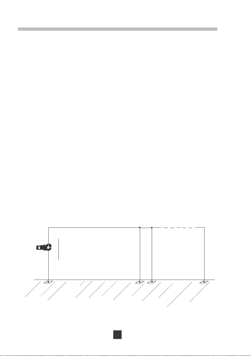
PRINCIPLE OF MEASUREMENT
The diagram below of the principle of measurement illustrates the general case of
measurement of a loop resistance consisting of:
- the ground rod Rx
- the Earth
- n ground rods
- a guard wire looping together all these earths
- The generating winding of the clamp develops an AC voltage with a constant
level E.
- The current measurement winding in the clamp has the value I = E/R
Knowing E set by the generator and I measured, we can deduce R
(value displayed on the clamp).
loop
loop
- More generally, this principle makes it possible to find defective earths. In fact, the
loop resistance is composed of:
R
(value to be found)
x
R
(value normally very low less than 1 Ω).
earth
R
// R2 ...// Rn (negligeable value: case for multiple parallel earths).
1
R
R
By approximation, R
If this value is very high, an inspection of this earth rod is strongly recommended.
(value normally very low, less than 1 Ω).
guard wire
= Rx + R
loop
I
+ (R1 // R2 ...// Rn) + R
earth
▼
Rx
▼
E
R earth
loop
= Rx.
Guard wire
guard wire
R1 R2 Rn
32
Page 9

OPERATION
ON/OFF OPERATION
ON/OFF switches ON, OFF, and gives access to the secondary functions of the
instrument.
When switched ON, if the ON button is still pressed, the whole display is lit. After being
pressed for 2 seconds, the remaining service life of the battery is displayed as a %
(display of flashing
recordings that have already been carried out (displays flashing MEM symbol).
As soon as it is switched ON, the clamp configures itself for resistance measurement (Ω).
The buzzer function is activated or not (on models C.A 6412, C.A 6415 or C.A 6415R),
depending on its state when the clamp was last turned off. This is the same for the
memory and alarm functions on models C.A 6415 and C.A 6415R.
CHOICE OF THE MEASUREMENT UNIT
symbol). Model C.A 6415 also states the number of
Measurement in
After pressing ON or after switching on, the instrument performs a resistance
measurement.
ΩΩ
Ω
ΩΩ
OL on the main display indicates that the value of resistance measured exceeds the
measurement range.
----- on the main display indicates either that the clamp is open, or that dirt is stopping
the clamp from closing correctly.The symbol is present on the display.
Measurement in A (models C.A 6412, C.A 6415 and C.A 6415R only)
After A is pressed, the instrument performs a current measurement.
OL on the main display indicates that the value of the current measured exceeds the
measurement range.
HOLD DIGITAL VALUE ON THE DISPLAY
This function is accessible with the HOLD button, only on measurement mode.
Press HOLD to freeze the last measurement displayed. The HOLD symbol is
displayed and the A, Ω and AL (models C.A 6412, C.A 6415 and C.A 6415R only)
buttons are inoperative. Recording of the measurement is possible if memory mode is
ON (C.A 6415 and C.A 6415R exclusively). In this case, the NOISE and R < .1
are also recorded in memory if displayed.
Press the HOLD button again to reset the instrument to instantaneous measurement
mode and HOLD disappears from the display.
33
ΩΩ
Ω symbol
ΩΩ
Page 10

ALARMS (C.A 6415 and C.A 6415R exclusively)
Operation of the alarm
On resistance measurement, the alarm function is swiched ON with the AL button (the
AL symbol and the value of the alarm threshold are displayed).
A switch located inside the instrument allows the choice of the type of alarm used:
- Low alarm: indicates measurements below the alarm threshold.
- High alarm: indicates measurements above the alarm threshold.
When supplied, the switch is set to the high alarm position. To modify the type of alarm,
unscrew the back of the instrument and change the position of the switch (see diagram
below).
remove the back of the instrument
measurement
head (red)
Switches:
flexible green
screen
-Down (OFF):
high alarm
-Up (ON):
low alarm
34
printed
circuit
battery
printed circuit
with its
components
Page 11

According to the type of alarm selected, crossing of the alarm threshold will be
indicated by the appearance of or and a continuous beep at high or low frequency.
Press the AL button again to exit the alarm function (the AL symbol disappears).
If the instrument is switched OFF, without the alarm mode being exited, this
configuration will be saved. The instrument will thus automatically switch the alarm
function ON again when the instrument is next switched ON.
Setting the alarm threshold
To programme the alarm threshold for resistance measurement it is necessary to first
press the ON + AL sequence.
The AL symbol is displayed and the last digit of the threshold value flashes, as a
reminder that you are in threshold reset mode. This value is changed by pressing the
▼
Ω Ω
Ω button (increase) or A button (decrease). This new threshold value will be kept until
Ω Ω
▼
it is again changed, even after the clamp has been switched OFF.
The high alarm threshold can be between 1 and 199 Ω. It is programmed in at the
factory before delivery of the clamp.
OFF (instrument switched off) exits alarm threshold programming mode.
MEMORY (C.A 6415 and C.A 6415R exclusively)
Zero reset of memory
Press the ON + MEM sequence for 3 seconds to display
memoory procedure. At the 5th beep, the memory is cleared. Return to resistance
measurement is then automatic.
, this starts the clear
Recording a measurement
The recording of a measurement is only possible if the memory is switched on with the
ON + A sequence (MEM symbol displayed).
Press MEM to record the displayed value. The number of values in memory goes up
by 1 and a long beep confirms the recording.
If the symbol or the symbol is continuously displayed, recording is
impossible because the clamp is not correctly closed or the battery is too low.
When the 99th value is recorded, the MEM symbol flashes to tell the user that the
memory is full. It is then no longer possible to record new values. If MEM is pressed
again there is no effect other than that a beep is emitted to indicate that recording is
prohibited. The memory should be reset to zero (after being re-read if necessary).
35
Page 12

Press sequence ON + A to exit the instrument from memory mode (the MEM symbol
disappears from the display). If the instrument is switched off without memory mode
being exited, this configuration will be saved.
The instrument will therefore automatically reset to memory mode when it is next
switched on again.
Unless the memory is reset to zero, all the recordings are saved even after the
instrument is switched off or the battery disconnected (instrument OFF).
Reading recorded measurements
A short press on ON + MEM allows you to consult the memory.
MR symbol is displayed, as well as the number of the recording shown.
The
if ON + MEM are pressed and held for 6 seconds the memory will be reset to
zero.
▼
To display the values recorded in memory press the
▼
ΩΩ
Ω button (subquent recordings)
ΩΩ
and A (previous recordings).
The last digit of the recording number flashes to show that you are in read mode.
OFF (instrument off) allows the user to exit read memory mode.
SPECIAL FUNCTIONS
Auto ON/OFF
Your clamp is fitted with a battery system for economising battery power.
After approximately 5 minutes operation of the battery, if no button on the clamp has
been pressed, the instrument switches off automatically. 15 seconds before switching
off, a short beep warns the user, whilst the display starts to flash.
Auto Off can be deactivated by pressing the sequence ON + HOLD. In this case, the
instrument operates continuously (the symbol P is displayed) and the instrument
will only switch off when the user presses the OFF button.
Continuous operation is cancelled when the instrument is switched off.
Buzzer ON/OFF (models C.A 6412, C.A 6415 and C.A 6415R only)
Your clamp is fitted with a powerful buzzer whose different beeps indicate the state
of the instrument (see: Table of buzzer operation in Appendix).
If necessary, the buzzer operation can be switched OFF by pressing the sequence
ΩΩ
ON +
Ω. In this case the
ΩΩ
symbol disappears.
This deactivation of the buzzer will be saved on models, even after the instrument
is switched off. Press ON +
ΩΩ
Ω again to switch on the buzzer again (the symbol
ΩΩ
will appear again).
36
Page 13

SPECIAL SYMBOLS
In addition to the battery service life which is accessible when ON is pressed when
switching on, the clamp can display the battery level at any time:
For an alkaline battery if the service life is less than 25 %: the symbol flashes,
indicating that around 50 resistance measurements can be made with guaranteed
values. If it is less than 20 %: the symbol is continuously displayed, measurements are only indicative, they can not be recorded in the memory.
When the battery is flat, the instrument switches off automatically.
NOISE
This symbol appears when a disturbing current which is too great circulates in the earth
conductor, i.e. when the product U = R
40 V. Resistance measurement is not then guaranteed.
This symbol appears when the clamp is open or incorrectly closed. It may be displayed
on the screen when the jaw faces are not perfectly clean.
The clamp can not make a measurement in this case.
ΩΩ
R < .1
Ω
ΩΩ
loop
(I
disturb. + Imeas.
) is greater than approximately
This symbol appears when the resistance measured is less than 0.1 Ω
OL
This appears on the digital display when the measured value exceeds the measurement
range (1200 Ω in resistance measurement on all models, 30 A in current measurement
on the C.A 6412, C.A 6415 and C.A 6415R accompanied with an intermittent beep).
37
Page 14

SUMMARY OF FUNCTIONS
Function Pushbutton
All models
ON/OFF * ON/OFF
HOLD display HOLD
P - Switch Auto Off ON/OFF ON + HOLD
*
The instrument is automatically on Ω units each time it is switched on.
Models C.A 6412, C.A 6415 and C.A 6415R only
Ω measurement * Ω
A measurement A
- Switch buzzer ON/OFF ** ON + Ω
*
The instrument is automatically on Ω units each time it is switched on.
**
Function saved, even after the instrument is switched off.
Model C.A 6415 and C.A 6415R exclusively :
Programming alarm threshold in Ω ON + AL
then
AL - Switch alarm ON/OFF**
▼
ΩΩ
Ω or A
ΩΩ
AL
▼
MEM - Access to memory mode** ON + A
Record measurement MEM
MR - Re-read recorded measurements ON + MEM (press < 2 s)
then Ω or A
Reset memory to zero ON + MEM (press > 6 s)
Function saved, even after the instrument is switched off.
**
38
▼
▼
Page 15

EXAMPLES OF DISPLAYS
- Buzzer ON
- Measurement of a loop resistance of 28.1 Ω
-8 recorded values in the memory
(C.A 6415 and C.A 6415R exclusively)
-Battery o.k.
-Clamp correctly closed
-No interference current disturbing the
measurement
-Alarm off (C.A 6415 and C.A 6415R
exclusively)
- Buzzer ON
-Display HOLD on the last measurement of
16.8 A (C.A 6412, C.A 6415 and C.A 6415R
only)
-9 measurements have been recorded
(C.A 6415 and C.A 6415R exclusively)
- The battery is low and must be changed,
nevertheless the measurement is still valid.
- Buzzer ON
- The current measurement is less than 0.1 Ω,
the displayed value (0.08 Ω) is therefore not
guaranteed.
- The memory is full because 99 values are
recorded (C.A 6415 and C.A 6415R
exclusively).
- The alarm threshold, set at 15 Ω, is on. The
low alarm arrow is displayed to indicate that
this threshold has been crossed (C.A 6415
exclusively).
-A continuous low frequency beep is emitted
(C.A 6415 and C.A 6415R exclusively).
39
flashing
flashing
Page 16

EXAMPLES OF USE
TESTING A LOOP CONNECTED TO AN EXTENDED EARTH
- In some countries (US, Northern Europe, ...) the electricity supply company brings
the live, negative and earth conductors to the final user. In order to get a good quality
for the earth present throughout the distribution network, an extended earth is
constituted from all the local earths in parallel: earths of electricity pylons, earths for
buildings, ...
- The railways are particularly protected from the risks of lightning or excess voltage.
The catenary carrying pylons, the rails and sometimes even the fencing is
connected to the earth. In addition, to get a very low value earth resistance, an
interconnection between pylons - rails - fencing is made thus creating a multiple
parallel earth.
-In order to protect lines from any disturbance, "FRANCE TELECOM" insulates the
cables by means of a conductive sheath regularly connected to the earth throughout
its length.
In the cases cited above, to rapidly check the efficiency of these multiple earths:
- successively insert the clamp around each conductor connected to the earth
- read the value attained in Ω on the display
-the resistance of the earth in question will be less than or equal to the value
measured in this way.
40
Page 17

Analysis: The values read must never exceed a few ohms, or a few tens of ohms.
Higher values indicate the presence of a fault in the earth loop tested. Comparison with
nearby loop values will allow you to locate the common faulty link. This must be
subjected to further investigation: measurement of the continuity of the cable
connected to the earth, measurement of the resistance of local earths isolated from
the rest of the network, ...
Note: With models C.A 6415 and C.A 6415R it is also possible to record each
measurement during a series of tests, and to trigger an alarm if the fixed threshold
value put in by the operator is exceeded.
TESTING THE EQUIPOTENTIAL OF GROUNDING SYSTEMS
In establishments equipped with sensitive
electronics, protection is reinforced by a mesh of
grounding conductors, connected to multiple
earths. An extended earth is thus obtained which
makes it possible to produce a grounding system
without equipotential defects.
To guarantee a perfect flow of loads to the earth,
the resistive values of the loops formed by these
means must be low, but also, practically identical.
A loop with a value different from the rest of the
grounding system would be likely to create a
difference in potential, for example, in case of
lightning. This excess voltage is likely to cause serious damage to sensitive equipment.
Your clamp allows you to easily check your earth meshes, and therefore to guarantee
the equipotential:
- Measure the resistive value of each loop.
- Compare all the measurements with one another.
Analysis: See preceding analysis and note.
General remark on loop measurement
Note that for the measurements discussed up to this point, we mention "loop
resistance". Given the principle of the measurement clamp and the measurement
signal generated (2403 Hz for C.A 6410, C.A 6412 or C.A 415 and 1358 Hz for C.A 6415R),
it would be more correct to speak of the measurement of "loop impedance".
In fact, in practice the reactive values in series in the loop (in line choke) can be ignored
in relation to the loop resistance (Z ≈ R).
41
Page 18

SPECIFICATIONS
GENERAL SPECIFICATIONS
Conformity to the EN 6110-1 Ed 95 standard:
Instrument completely protected by double insulation
EN 61010-2-032 Ed 95, 150 V, category III and degree of pollution 2 (class 2).
Leakage line and distance in the air: 3.3 mm minimum
Emission: NF EN 61326-1, ed 98
Immunity: NF EN 61326-1, ed 98
Limiting overloads: permanent current 100 A max. (50/60 Hz)
transient currents (< 5 s) 200 A (50/60 Hz)
Case: polycarbonate
Dimensions: 55 x 100 x 240 mm
Max. Clamping diameter: 32 mm Ø
Weight: approx. 1 kg
Watertightness:IP30, Group III equipment as per EN 60529 Ed 92
IK04, as per EN 50102 Ed 95
Power supply:- 9 V alkaline battery 6LF22 or equivalent
-average consumption: approx. 40 mA
- average service life: approx. 8 hours,
i.e. 1000 measurements of 30 seconds.
With a rechageable NiCad battery, the average service life is
approx. 400 measurements of 30 seconds.
Note: extreme environmental conditions may disturb the internal microprocessor.
Simply disconnecting the battery may be sufficient to eradicate this malfunction.
42
Page 19

METROLOGICAL SPECIFICATIONS
Reference conditions
Distortion conditions Reference conditions
Ambient temperature 23°C ± 3 K
Relative humidity 50% RH ± 10%
Battery voltage 8 V ± 0.2 V
External magnetic field < 40 A/m
External electric field < 1 V/m
Operating position Clamp horizontal
Position of conductor in the clamp centred
Proximity to metallic mass > 10 cm
Loop resistance Non choke resistance
Current measured, sinusoidal frequency 50 Hz
Rate of distorsion < 0.5%
Interference current on measurement of loop resistance
nil
Climatic conditions
▼
RH % (with condensation)
100
90
80
70
60
50
40
30
20
10
400 to 800 mm Hg
-40 -30 -20 -10 0 10203040506070
1 Reference range
2 Operating range
3 Storage range: (internal or
external use of equipment)
3
2
1
43
3
▼
°C
Page 20

ΩΩ
Ω function (resistance measurement) for reference conditions
ΩΩ
Measurement 0.1 1.0 50.0 100 200 400 600
ranges in
ΩΩ
Ω to 1.00
ΩΩ
(1)
to 50.0 to 100.0 to 200 to 400 to 600 to 1200
Resolution 0.01 Ω 0.1 Ω 0.5 Ω 1 Ω 5 Ω 10 Ω 50 Ω
Accuracy ±1.5% ±1.5% ±2% ± 3% ± 6% ±10% approx. 25 %
±0.02 Ω ±0.1 Ω ±0.5 Ω ± 1 Ω ± 5 Ω ±10 Ω ±50 Ω
(1)
Indication of measurements up to approximately 0.07 Ω, but accuracy is not guaranteed below
0.1
Ω
Hysteresis
of the display
Switching of
automatic
ranges
± 20 to 30% of the resolution
Switching at 100 Ω for increasing value
and at 91Ω for decreasing value
Approx. 60 mV rms at 2 403 Hz for C.A 6410, C.A 6412, C.A 6415
Loop voltage and 1358 Hz for C.A 6415R.
generated
(1)
Shape : sinusoidal
(For R loop of 1 Ω to infinity)
Alarm
(1)
The voltage generated in the loop is “pulsed “ in such a way as to save on the battery.
The loop is excited for approximately 60 ms, 4 times a second, i.e. 24% of the time.
- Threshold range: 1 Ω to 199 Ω
- Hysteresis: 3 times the resolution
"A" function (AC current measurement) for the reference conditions
Measurement range 0 ... 299 mA RMS 0.300 ... 2.999 A RMS 3.00 ... 29.99 A RMS
Resolution 1 mA 1 mA 10 mA
Accuracy in %
of the reading ± 2.5 % ± 2 mA ± 2.5 % ± 2 mA ± 2.5 % ± 20 mA
Switching of Switching at 3000 counts for increasing
automatic range value and at 270 counts for decreasing value
44
Page 21

Variations in the nominal working range
Influence Limit of Parameter Influence
(1)
parameter operating influenced
range typical Max.
Temperature - 10 °C to A 0.5 P/10°C 1.5 P/10°C + R
+55°C Ω (0.05 Ω + 0.5 P)/10°C (0.05 Ω +1.5 P)/10°C + R
Relative humidity 10 % RH to A 0.5 P P + R
90 % RH Ω 0.05 Ω + 0.5 P 0.05 Ω + P + R
Battery voltage 6.5 to 9.5 V A and Ω 0.1 P 0.25 P + R
Conductor position from edge A 0.05 P 0.2 P + R
in centre Ω 0.05 P 0.1 P + R
Clamp position ± 180 ° A and Ω 0.1 P 0.2 P + R
Proximity of earth 1 mm steel sheet
magnetic against jaw gap
Magnetic field
50/60 Hz
30 A/m Ω and A 0.05 P 0.1 P + R
Ω 0.1 P 0.5 P + R
Frequency 47 ... 800 Hz A 2 P 3 P + R
Disturbing current 3 % L 5 % L + R
50 ... 60 Hz (I
in the loop
Peak factor
(2)
(3)
+ I
meas.
x R
1.4 to 2.5
2.5 to 5 2 P 2.5 P + R
) Ω For I ≤ 1 A
disturb.
≤ 40 V With R
loop
A
1 P 1.5 P + R
measured
= 30 Ω
(1) P=Precision defined in the reference conditions for the measuring range considered
R=Resolution defined for the measuring range considered
% L = Error expressed as a percentage of the reading (L)
Example: For a measured value of 25
[0.05
Ω
+ (1.5 x 0.015 x 25)] / 10°C ±0.1 Ω or 0.61 Ω / 10°C ±0.1
Ω
at 20°C, the maximum influence of temperature is:
Ω
(2) The disturbing current at 50/60 Hz maximum is approximately 3.5 A for low loop resistance values (< 10 Ω).
Above approximately 40 V (at 50/60 Hz) in the measuring loop, the NOISE symbol comes on..
(3) Limited to 40 A peak
45
Page 22

MAINTENANCE
!
For maintenance, use only specified spare parts. The manufacturer will not be
held responsible for any accident occuring following a repair done other than
by its After Sales Service or approved repairers.
CLEANING
- The jaw faces must be cleaned with a soft cloth.
- Use only a damp cloth to clean the case. Abrasive products or solvants are
prohibited. A little soap may nevertheless be used.
CALIBRATION
-Calibration must be done more frequently for more intensive use.
-With the calibration loop which is sold as an accessory, you may yourself at any time
check the accuracy of your clamp. To do this enclose the calibration loop in the jaws
of the clamp. Switch ON your clamp, then compare the displayed measurement with
the value marked on the enclosed segment. Proceed like this for each calibration
value of the calibration loop. Depending on the measurement differences read, you
can decide on the necessity of having your clamp recalibrated. In this case, get in
touch with your supplier.
Calibration values of the loop: 7.9 Ω / 12.4 Ω / 22 Ω / 49.5 Ω / 198 Ω
Accuracy of these values 0.3 % typical and and 0.5 % max.
Note: Add the accuracy of the instrument to the accuracy of the calibration values.
CHANGING THE BATTERY
-With the instrument switched OFF, the battery is changed by unscrewing the two
screws on the back of the instrument. When the battery is disconnected, the
configuration (buzzer, ...), as well as the recorded measurement values (C.A 6415 and
C.A 6415R), and the value of the alarm threshold (C.A 6415 and C.A 6415R) are
saved.
- Replace the used battery by a new one of the same type (alkaline 9 V battery or
equivalent).
- Respect the polarity when connecting.
46
Page 23

CALIBRATION CHECK
!
It is essential that all measuring instruments are regularly calibrated.
We advise you to check this instrument at least once a year. For checking and calibration
of your instrument, please contact our accredited laboratories (list on request) or the
Chauvin Arnoux subsidiary or Agent in your country.
REPAIR
Repairs under or out of guarantee: please return the product to your distributor
47
Page 24

APPENDIX
Descriptive table for operation of buzzer
Length and frequency of beep
65 ms 125 ms 250 ms Continuous
2.5 kHz 4 kHz 2.5 kHz 1 kHz 1 kHz 4 kHz
Press button X
- Button prohibited
- Recording not possible X
Noise
Current overload
Alarm crossed low high
Variation after
memoristation or clear X
Warning before 5 beep
initialisation
Warning before Auto off. X
Inter-
mittent
Inter-
mittent
alarm alarm
48
 Loading...