

Page 1
C.A 5233
MULTIMÈTRE
MULTIMETRO
FRAN
Ç
AIS
Notice de fonctionnement
Manual
de instrucciones
MULTIMETER
MULTIMETER
MULTIMETRO
ENGLISH
DEUTSCH
ITALIANO
ESPAŇOL
User’s manual
Bedienungsanleitung
Manuale d’uso
Page 2

Français
PRÉCAUTIONS D’EMPLOI
Cet appareil est conforme à la norme de sécurité IEC 61010-1
(Ed 2 – 2001) pour des tensions de 600 V en catégorie IV à une
altitude inférieure à 2000 m et en intérieur, avec un degré de
pollution au plus égal à 2.
Le non-respect des consignes de sécurité peut entraîner un
risque de choc électrique, de feu, d'explosion, de destruction de
l'appareil et des installations.
N’utilisez pas l'appareil en atmosphère explosive ou en
présence de gaz ou fumées inflammables.
N’utilisez pas l'appareil sur des réseaux de tensions
ou de catégories supérieures à celles mentionnées.
Respectez les tensions et intensités maximales assignées
entre bornes et par rapport à la terre.
N’utilisez pas l'appareil s'il semble endommagé, incomplet ou
mal fermé.
Avant chaque utilisation, vérifiez le bon état des isolants des
cordons, boîtier et accessoires. Tout élément dont l'isolant
est détérioré (même partiellement) doit être consigné pour
réparation ou pour mise au rebut.
Utilisez des cordons et accessoires de tensions et de
catégories au moins égales à celles de l'appareil.
Respectez les conditions environnementales d'utilisation.
Respectez strictement les caractéristiques des fusibles.
Déconnectez tous les cordons avant ouverture de la trappe
d'accès aux fusibles.
Ne modifiez pas l'appareil et ne remplacez pas des
composants par des équivalences. Les réparations ou les
ajustages doivent être effectués par du personnel compétent
agréé.
Remplacez la pile dès l'apparition du symbole sur
l'afficheur. Déconnectez tous les cordons avant ouverture de
la trappe d'accès à la pile.
Utilisez des protections individuelles de sécurité lorsque les
conditions l'exigent.
Ne gardez pas les mains à proximité des bornes non
utilisées de l'appareil.
Lors de la manipulation des sondes ou des pointes de
touche, ne placez pas les doigts au-delà de la garde
physique.
2 - 138
Page 3

Français
CATÉGORIES DE MESURE
Définition des catégories de mesure selon la norme IEC 61010-1 :
CAT I : Circuits non reliés directement au réseau et spécialement
protégés.
Exemple: circuits électroniques protégés.
CAT II : Circuits directement branchés à l'installation basse tension.
Exemple : alimentation d’appareils électrodomestiques et d’outillage
portable.
CAT III : Circuits d’alimentation dans l'installation du bâtiment.
Exemple : tableau de distribution, disjoncteurs, machines ou
appareils industriels fixes.
CAT IV : Circuits source de l'installation basse tension du bâtiment.
Exemple : arrivées d’énergie, compteurs et dispositifs de protection.
English ......................................................................................... 30
Deutsch ........................................................................................ 57
Italiano .......................................................................................... 84
Español ........................................................................................ 111
3 - 138
Page 4

Vous venez d’acquérir un multimètre C.A 5233 et nous vous
remercions de votre confiance.
Pour obtenir le meilleur service de votre appareil :
Lisez attentivement cette notice de fonctionnement ;
Respectez les précautions d’emploi.
Signification des symboles utilisés sur l’appareil :
Risque de danger. L'opérateur s'engage à consulter la
présente notice à chaque fois que ce symbole de danger
est rencontré.
Fusible.
Pile 9V.
Le marquage CE indique la conformité aux directives
européennes.
Isolation double ou isolation renforcée.
Tri sélectif des déchets pour le recyclage des matériels
électriques et électroniques au sein de l'Union
Européenne. Conformément à la directive DEEE
2002/96/EC :
ce matériel ne doit pas être traité comme déchet ménager.
AC – Courant alternatif.
AC ou DC – Courant alternatif ou continu.
Terre.
Français
4 - 138
Page 5

Français
SOMMAIRE
1. PRÉSENTATION .......................................................................... 6
1.1 L’AFFICHEUR ................................................................................ 7
1.2 LES TOUCHES .............................................................................. 9
1.3 LE COMMUTATEUR ................................................................... 10
1.4 LES BORNES .............................................................................. 11
2. UTILISATION .............................................................................. 11
2.1 PREMIÈRE UTILISATION .......................................................... 11
2.2 MISE EN SERVICE DU MULTIMÈTRE ..................................... 12
2.3 ARRÊT DU MULTIMÈTRE ......................................................... 12
2.4 LA BÉQUILLE .............................................................................. 13
3. FONCTIONS................................................................................ 14
3.1 FONCTIONS DU COMMUTATEUR ........................................... 14
3.2 FONCTIONS DES TOUCHES .................................................... 18
4. CARACTÉRISTIQUES ................................................................ 21
4.1 CONDITIONS DE RÉFÉRENCE ................................................ 21
4.2 CARACTÉRISTIQUES AUX CONDITIONS DE RÉFÉRENCE 21
4.3 CONDITIONS D’ENVIRONNEMENT ......................................... 25
4.4 CARACTÉRISTIQUES CONSTRUCTIVES............................... 25
4.5 ALIMENTATION .......................................................................... 25
4.6 CONFORMITÉS AUX NORMES INTERNATIONALES ................. 26
4.7 VARIATIONS DANS LE DOMAINE D’UTILISATION................... 26
5. MAINTENANCE .......................................................................... 26
5.1 NETTOYAGE ............................................................................... 26
5.2 REMPLACEMENT DE LA PILE .................................................. 27
5.3 REMPLACEMENT DU FUSIBLE ................................................ 27
5.4 VÉRIFICATION MÉTROLOGIQUE ............................................ 27
5.5 RÉPARATION .............................................................................. 28
6. GARANTIE .................................................................................. 28
7. POUR COMMANDER ................................................................. 29
5 - 138
Page 6
Français
1. PRÉSENTATION
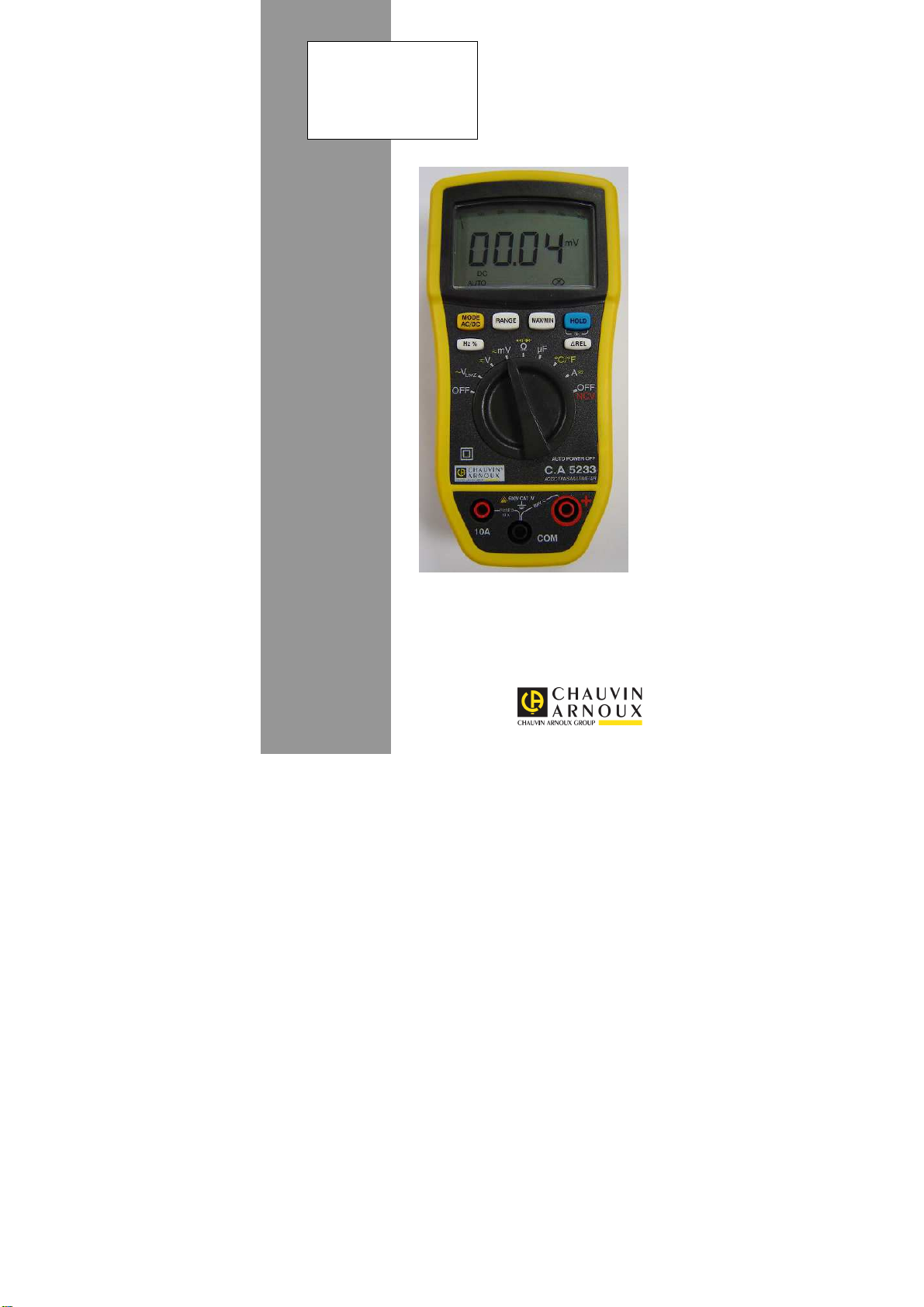
Le C.A 5233 est un multimètre numérique TRMS, portatif et
autonome, spécialement conçu pour regrouper en un seul
appareil les différentes fonctions de mesure des grandeurs
électriques suivantes:
Voltmètre en courant alternatif à basse impédance d'entrée
(mesure de tensions en électricité et en électrotechnique) ;
Voltmètre en courant alternatif ou continu à haute impédance
d'entrée (mesure de tensions en électronique) ;
Mesure de fréquence et Duty Cycle (rapport cyclique);
Ohmmètre ;
Test de continuité avec buzzer ;
Test de diode ;
Ampèremètre ;
Capacimètre ;
Thermomètre en °C ou °F par mesure et linéarisation de la
tension développée aux bornes d'un thermocouple de type K ;
Détection de présence de tension réseau sans contact
(fonction NCV présence de phase) .
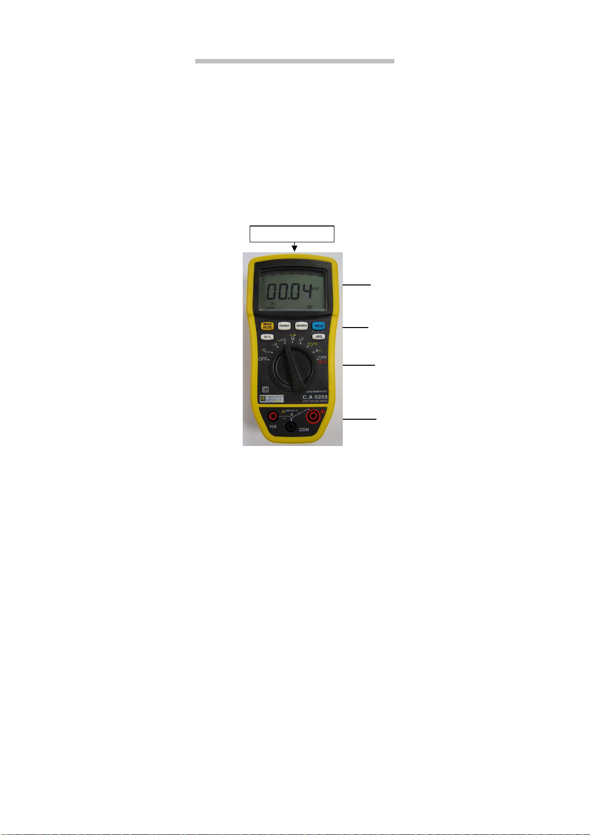
Figure 1 : le multimètre C.A 5233
Zone de détection NCV
6 - 138
1
2
3
4
Page 7

Français
1
2
4
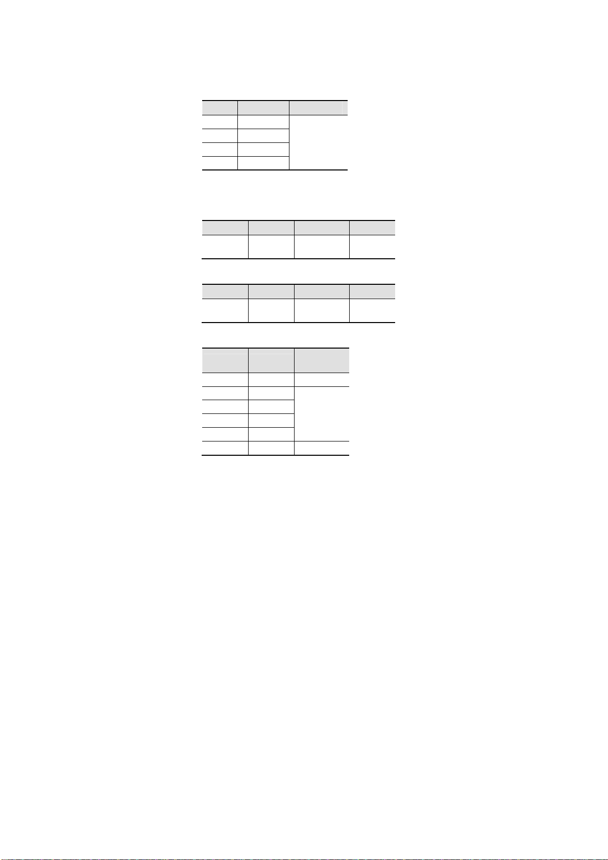
Rep.
1 Afficheur 1.1
2 Touches de fonction 1.2
3 Commutateur 1.3
4 Bornes 1.4
Désignation Voir §
1.1 L’AFFICHEUR
L’afficheur permet :
Un affichage de type analogique du paramètre mesuré grâce
au bargraphe, associé à l’affichage digital sur 6000 points.
Une lecture confortable des informations grâce au rétroéclairage de l’écran.
7 6 8 5
Figure 2 : l’afficheur
7 - 138
Page 8

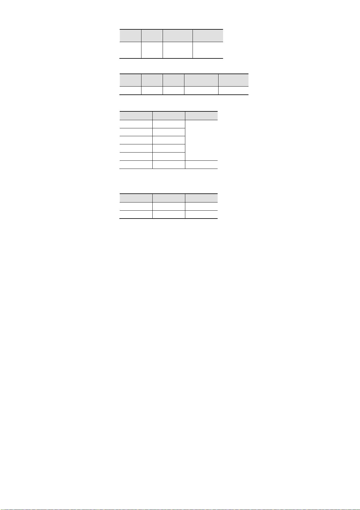
Rep.
Fonction Voir §
1 Bargraphe
2 Affichage (valeurs et unités de mesure) 3.1
3 Nature de la mesure (alternatif ou continu) 3.2.1
4 Mode automatique de sélection du calibre de
mesure
5 Indicateur de pile usagée 5.2
6 Test de continuité sonore
Test de diode
7 Affichage des modes sélectionnés 1.2
8 Mode Non Permanent : arrêt automatique de
l’appareil activé
1.1.1 Les symboles de l’afficheur
L’afficheur utilise les symboles suivants :
Symboles
AC
DC
AUTO
HOLD
MAX
MIN
REL
O.L
V
Hz
%
F
°C
°F
Courant alternatif
Courant continu
Changement automatique du calibre (voir § 1.1.3)
Mémorisation et affichage des valeurs mémorisées
Valeur RMS maximale
Valeur RMS minimale
Valeur relative
Dépassement des capacités de mesure (voir §1.1.2)
Volt
Hertz
Duty Cycle (rapport cyclique)
Farad
Degré Celsius
Degré Fahrenheit
Désignation
Français
3.2.2
3.1.3
3.1.4
3.2.1
8 - 138
Page 9
Français
A
Ω
n
µ
m
M
Ampère
Ohm
Préfixe nanoPréfixe microPréfixe milli-
k
Préfixe kiloPréfixe mégaTest de continuité sonore
Test de diode
Mode Non Permanent (arrêt automatique activé)
Indicateur de pile usagée
1.1.2 Dépassement des capacités de mesure
(O.L.)
Le symbole O.L. (Over Load) s’affiche quand le signal mesuré
dépasse les capacités du calibre de l’appareil.
1.1.3 Changement automatique du calibre de
mesure (Autorange)
Le symbole AUTO sur l’afficheur indique que l’appareil change
automatiquement le calibre de mesure pour effectuer la
mesure. Vous pouvez changer manuellement le calibre en
appuyant sur
(voir § 3.2.2).
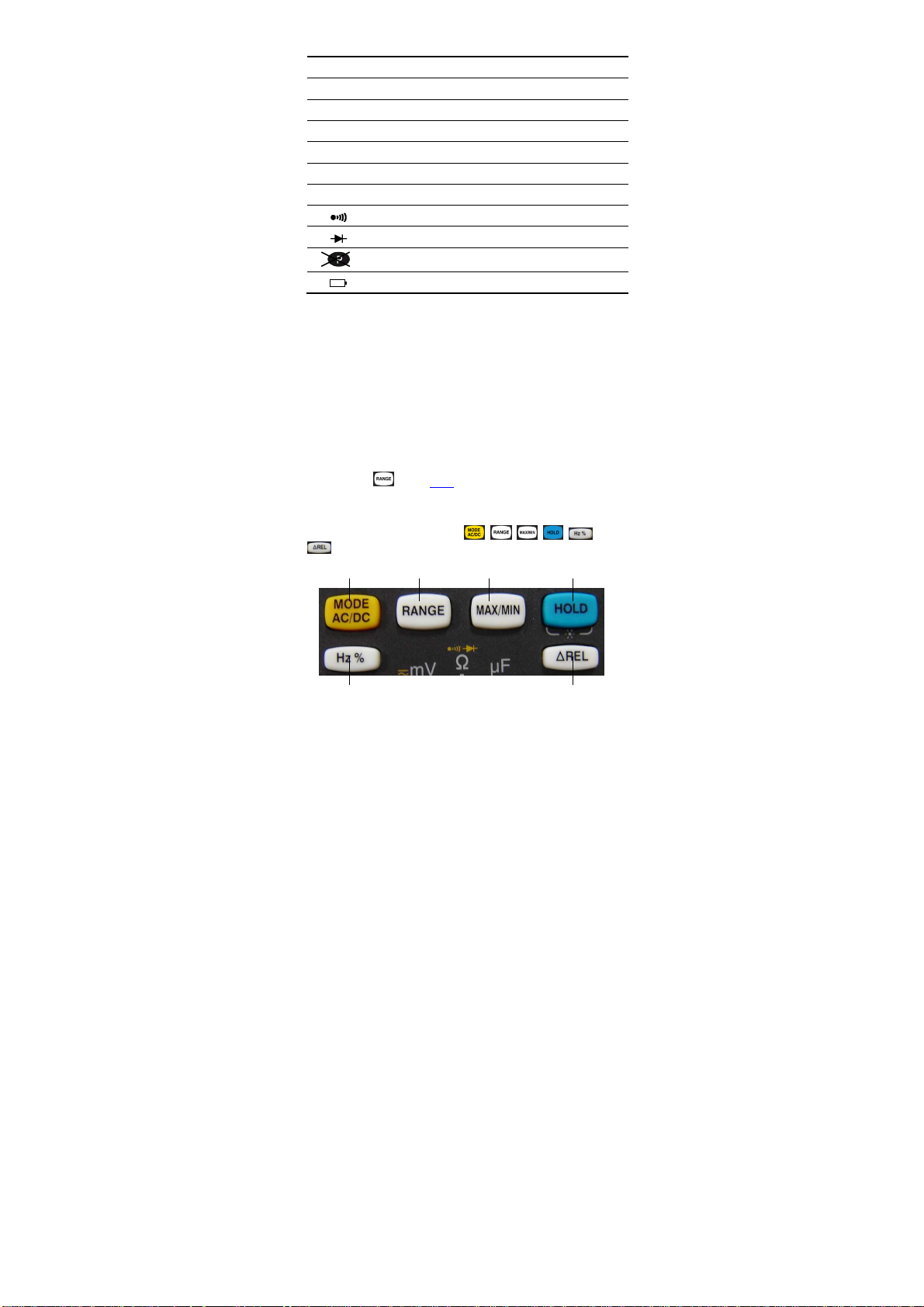
1.2 LES TOUCHES
Le clavier possède six touches : , , , , et
. Voici les touches du clavier.
1 2 3 4
5 6
9 - 138
Page 10
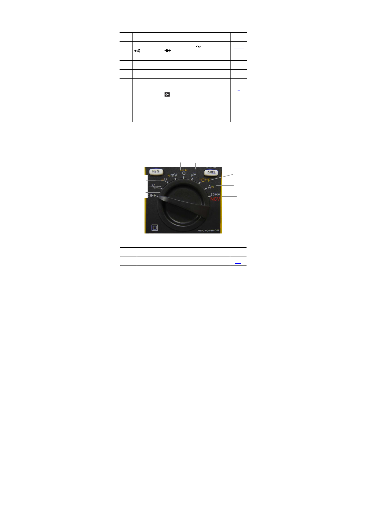
Figure 3 : les touches du clavier
2
9
Français
Rep.
1 Sélection du type de mesure (AC ou DC),
, °C, °F ou . Activation ou désactivation
Fonction Voir §
de l’arrêt automatique de l’appareil au démarrage
2 Sélection manuelle du calibre de mesure . 3.2.2
3 Activation ou désactivation du mode MAX/MIN 0
4 Maintien de l’affichage de la valeur mesurée .
Activation ou désactivation du rétro éclairage
bleu de l’écran ( ) (appui >2s)
5 Mesure de fréquence et de duty cycle en V AC et
A AC
6 Mesure de la valeur relative 3.2.6
1.3 LE COMMUTATEUR
Le commutateur possède neuf positions. Les fonctions sont
décrites dans le tableau ci-dessous :
4 5 6
3
1
3.2.1
0
3.2.5
7
8
Figure 4 : le commutateur
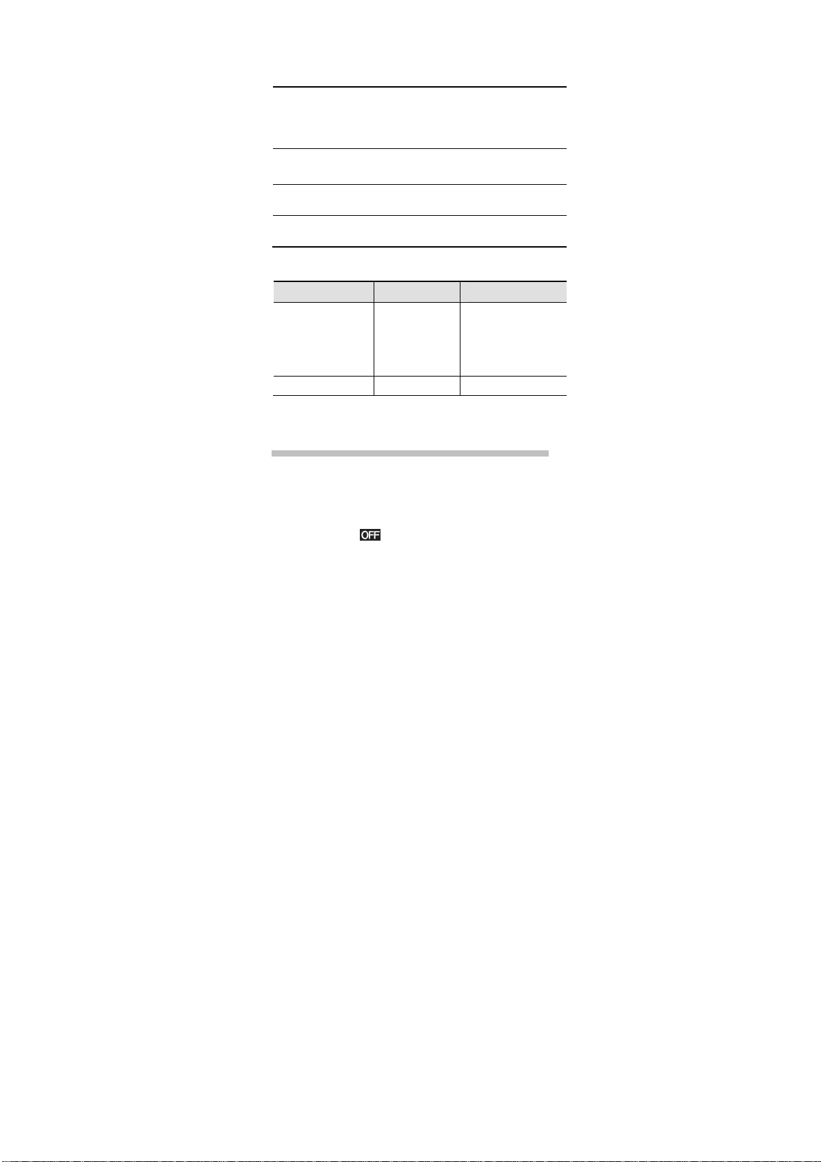
Rep. Fonction Voir §
1 Mode OFF – Arrêt du multimètre 2.3
2 Mesure de tension alternative en basse
impédance d’entrée (V
LowZ
)
3.1.1
10 - 138
Page 11
Français
3 Mesure de tension en AC ou DC (V) 3.1.1
4 Mesure de tension en AC ou DC (mV) 3.1.1
5 Mesure de résistance
Test de continuité
Test de diode
6 Mesure de capacité 3.1.5
7 Mesure de température en °C ou °F 3.1.6
8 Mesure d’intensité en AC ou DC 3.1.7
9 NCV (Non Contact Voltage) + Mode OFF
partiel du multimètre (fonction NCV active)
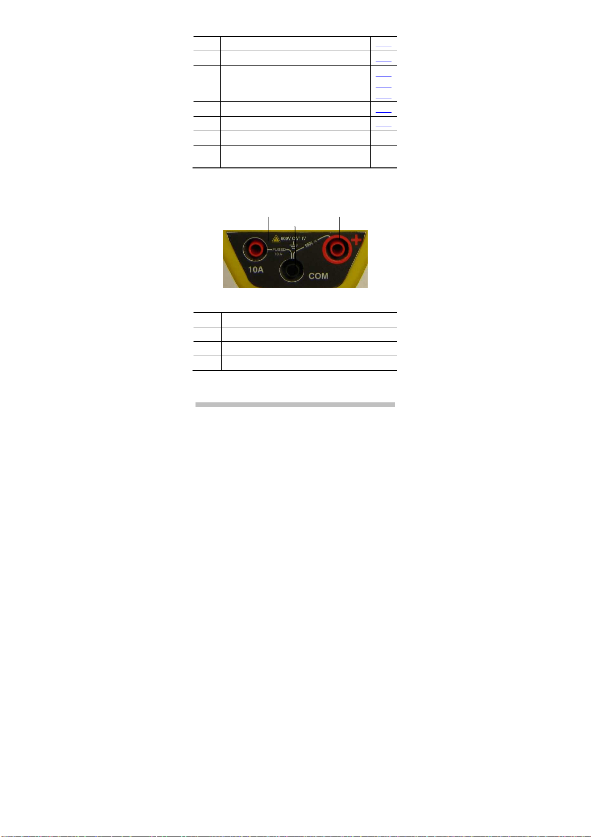
1.4 LES BORNES
Les bornes sont utilisées comme suit :
1 2 3
3.1.2
3.1.3
3.1.4
3.1.8
Figure 5 : les bornes
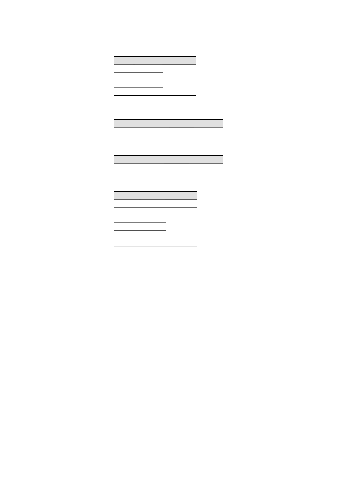
Rep. Fonction
1 Borne de mesure d’intensité (10 A)
2 Borne point froid (COM)
3 Borne point chaud (+)
2. UTILISATION
2.1 PREMIÈRE UTILISATION
Placez la pile fournie avec l’appareil comme suit :
11 - 138
Page 12
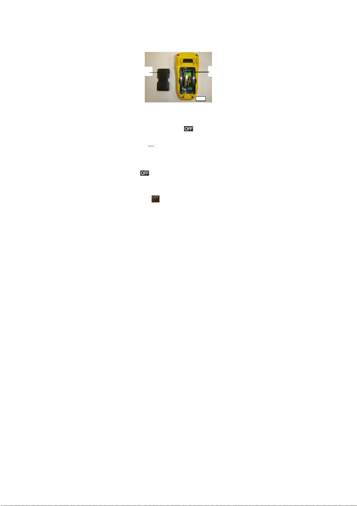
1. A l’aide d’un tournevis, dévissez les quatre vis a, b, c et d
c
Français
de la trappe (rep.1) situées à l’arrière du boîtier ;
2. Placez la pile dans son logement (rep.2) en respectant les
polarités ;
3. Revissez la trappe au boîtier . Remettez en place la
béquille.
a
1
b
d
2
Figure 6 : accès à la pile
2.2 MISE EN SERVICE DU MULTIMÈTRE
Le commutateur est sur la position
commutateur vers la fonction de votre choix. L’ensemble des
segments de l’afficheur apparaît pendant quelques secondes
(voir figure 2, § 1.1) puis l’écran de la fonction choisie s’affiche.
Le multimètre est alors prêt pour les mesures.
. Tournez le
2.3 ARRÊT DU MULTIMÈTRE
L’arrêt se fait soit de façon manuelle par retour du commutateur
en position
non-utilisation. A la 14
imminent du multimètre. Pour réactiver l’appareil, appuyez sur
une touche du clavier.
Nota : la position n’arrête pas totalement le multimètre,
celui-ci reste actif pour la détection de présence de tension
réseau sans contact (NCV).
, soit automatiquement après 15 minutes de
ème
minute, 5 bip préviennent de l’arrêt
12 - 138
Page 13
Français
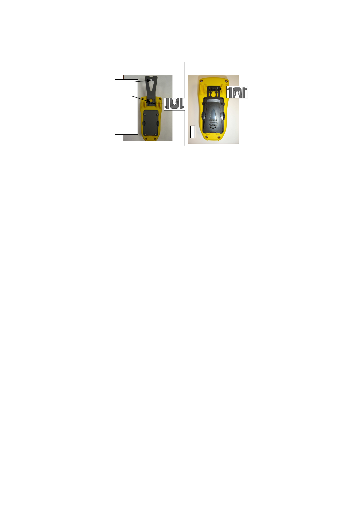
2.4 LA BÉQUILLE
Deux positions de béquille sont possibles, soit accrocher le
multimètre (position 1), soit le poser sur un support en position
inclinée (position 2). Pour changer la position de la béquille,
procédez comme suit :
Positon 1 : positionnez la
béquille vers le haut :
Zone
d’accrochag
e pour
accessoire
de fixation
multipositions
Position 2 : positionnez la
béquille vers le bas :
13 - 138
Page 14
3. FONCTIONS
3.1 FONCTIONS DU COMMUTATEUR
Pour accéder aux fonctions du commutateur, placez le
commutateur sur , , , , , , ou
.
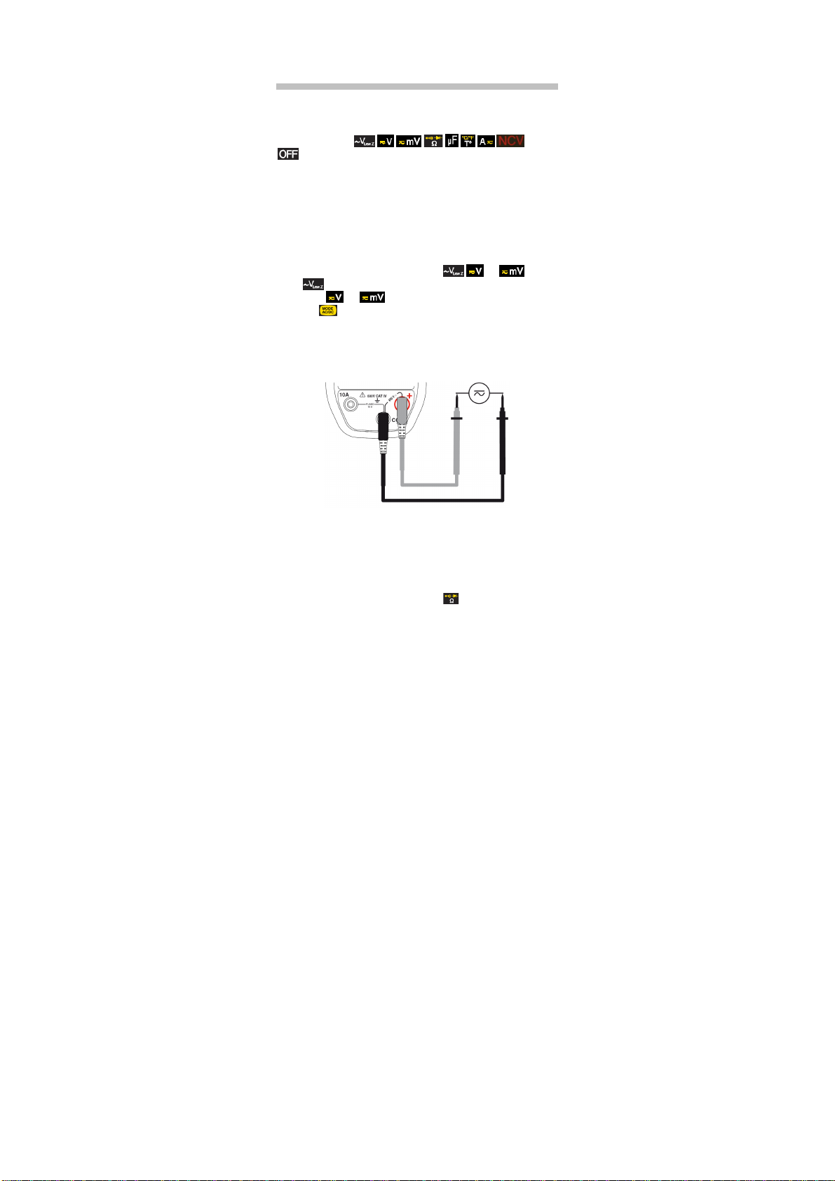
3.1.1 Mesure de tension
L’appareil mesure :
La tension alternative en basse impédance d’entrée (V
La tension continue (DC) ;
La tension alternative (AC).
Pour mesurer une tension, procédez comme suit :
4. Positionnez le commutateur sur , ou ; en
5. Pour ou ,sélectionnez AC ou DC en appuyant
6. Branchez le cordon noir sur la borne COM et le cordon
7. Placez les pointes de touche aux bornes du circuit à
l’appareil est uniquement en mode AC ;
sur . Par défaut, l’appareil est en mode DC . En
fonction de votre sélection, l’écran affiche DC ou AC ;
rouge sur « + » ;
mesurer ;
Français
) ;
LOWZ
La valeur de la tension mesurée s’affiche à l’écran.
3.1.2 Mesure de résistance
Attention : toutes les mesures de résistance doivent se faire
hors tension.
Pour mesurer la résistance, procédez comme suit :
8. Positionnez le commutateur sur ;
9. Branchez le cordon noir sur la borne COM et le cordon
rouge sur « + » ;
14 - 138
Page 15
Français
10. Placez les pointes de touche aux bornes du composant
ou du circuit à mesurer ;
La valeur de la résistance mesurée s’affiche à l’écran.
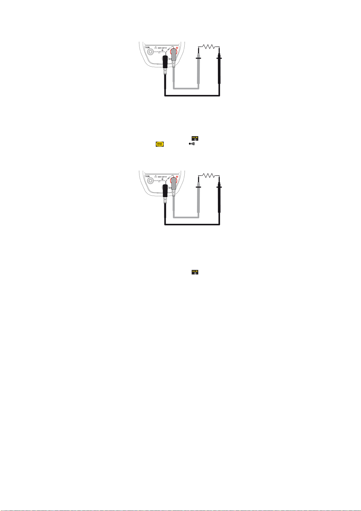
3.1.3 Test de continuité avec Buzzer
Attention : toutes les mesures de continuité doivent se faire
hors-tension.
Pour tester la continuité électrique, procédez comme suit :
11. Positionnez le commutateur sur ;
12.
Appuyez sur
. Le symbole
s’affiche ;
13. Branchez le cordon noir sur la borne COM et le cordon
rouge sur « + ».
14. Placez les pointes de touche aux bornes du composant
ou du circuit à tester ;
Le signal sonore du buzzer indique la continuité et la valeur de
la résistance mesurée s’affiche à l’écran.
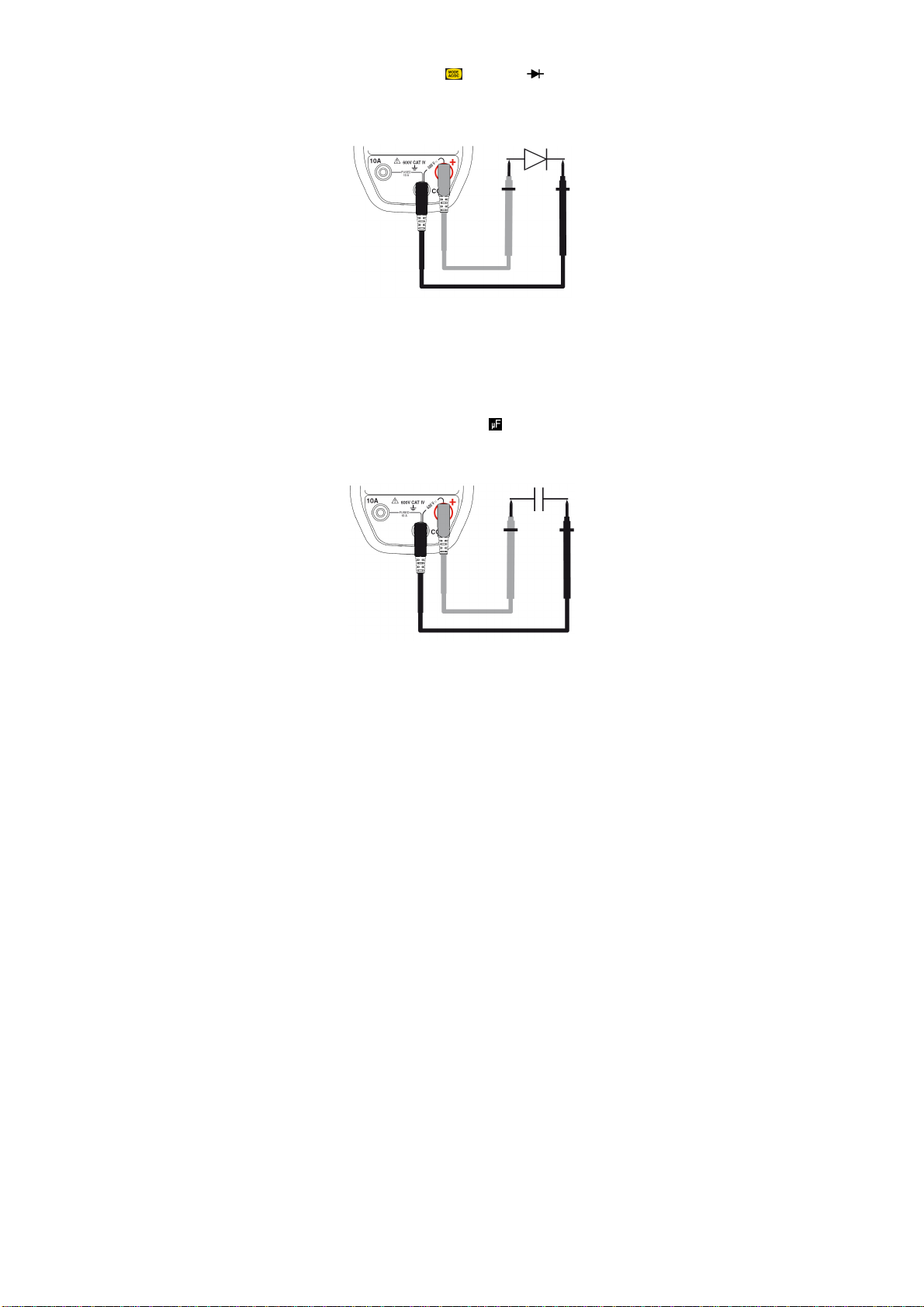
3.1.4 Test de diode
Attention : toutes les mesures de test diode doivent se faire
hors-tension.
Pour effectuer un test de diode, procédez comme suit :
15. Positionnez le commutateur sur ;
15 - 138
Page 16
Français
16. Appuyez deux fois sur
17. Branchez le cordon noir sur la borne COM et le cordon
. Le symbole
s’affiche ;
rouge sur « + » ;
18. Placez les pointes de touche aux bornes du composant ;
La valeur de la tension développée s’affiche à l’écran.
3.1.5 Mesure de capacité
Attention : toutes les mesures de capacités doivent se faire
hors-tension. Respectez les polarités de branchement (+ à la
borne rouge, - à la borne noire).
Pour mesurer la capacité, procédez comme suit :
19. Assurez-vous que la capacité à mesurer soit déchargée ;
20.
positionnez le commutateur sur ;
21.
Branchez le cordon noir sur la borne COM et le cordon
rouge sur « + » ;
22. Placez les pointes de touche aux bornes du composant.
La valeur de la capacité mesurée s’affiche à l’écran.
16 - 138
Page 17
Français
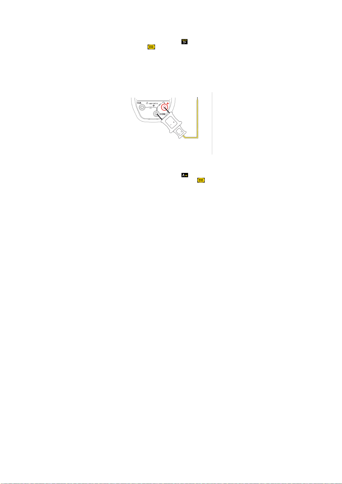
3.1.6 Mesure de température
Pour mesurer la température, procédez comme suit :
23. Positionnez le commutateur sur ;
24.
Appuyez sur
température (°C ou °F) ;
Remarque : l’unité affichée par défaut est le °C.
25. Branchez l’adaptateur pour sonde de température (rep.1)
aux bornes COM et « + » en respectant les polarités ;
26. Branchez la sonde de température (rep.2) sur l’adaptateur
en respectant les polarités.
Nota : si sonde non branchée ou coupée, l’afficheur indique
OL.
pour sélectionner l’unité de l’échelle de
La valeur de la température du thermocouple s’affiche à l’écran.
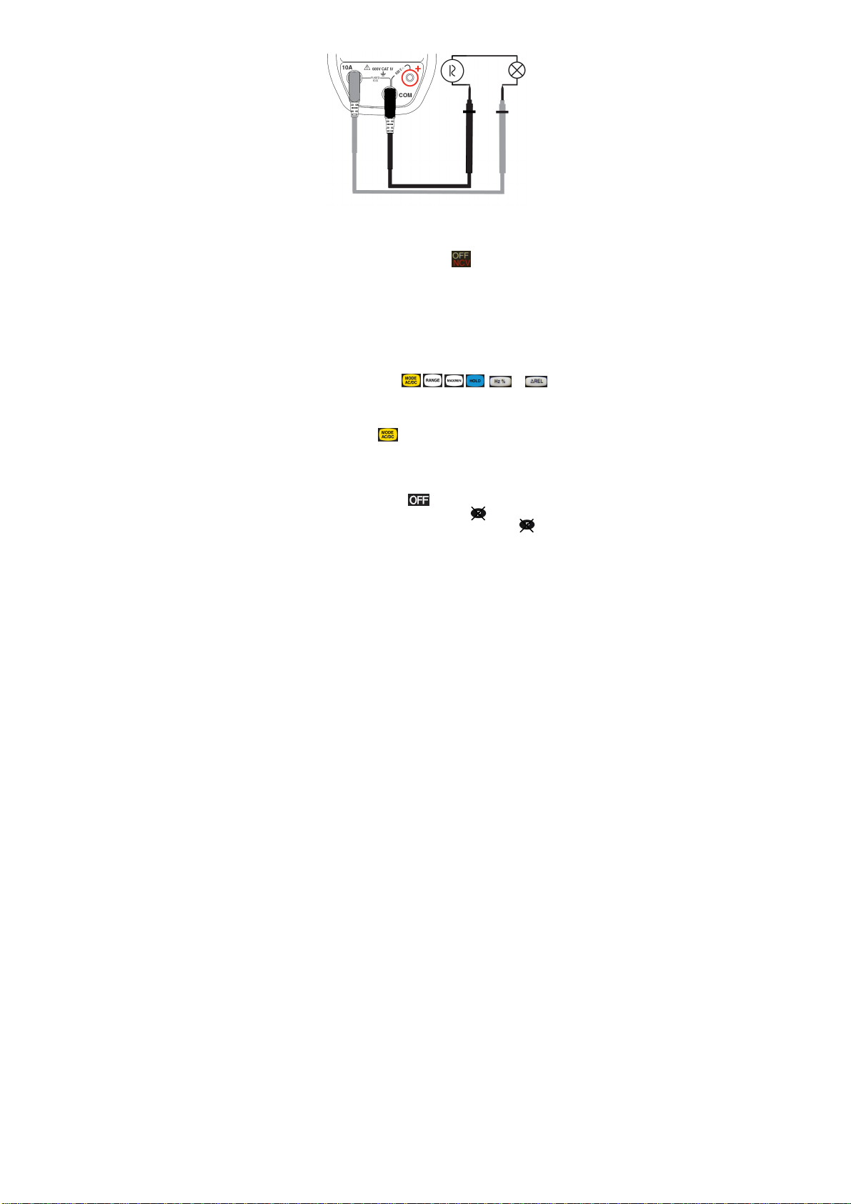
3.1.7 Mesure d’intensité
27. Positionnez le commutateur sur ;
28. Sélectionnez AC ou DC en appuyant sur . Par défaut,
l’appareil est en mode DC. En fonction de votre sélection,
l’écran affiche AC ou DC ;
29. Branchez le cordon noir sur la borne COM et le cordon
rouge sur « 10A » ;
30. Connectez le multimètre en série dans le circuit.
17 - 138
Page 18
Français
La valeur de l’intensité mesurée s’affiche à l’écran.
3.1.8 Non Contact Voltage NCV
31. Positionnez le commutateur sur ;
32.
Approchez le C.A 5233 (zone de détection NCV) du (des)
conducteur(s) potentiellement sous tension (présence de
phase) ;
33. Si présence de tension réseau de 230V (modèle Europe),
le rétro-éclairage s’allume en rouge ; dans le cas
contraire, il reste éteint.
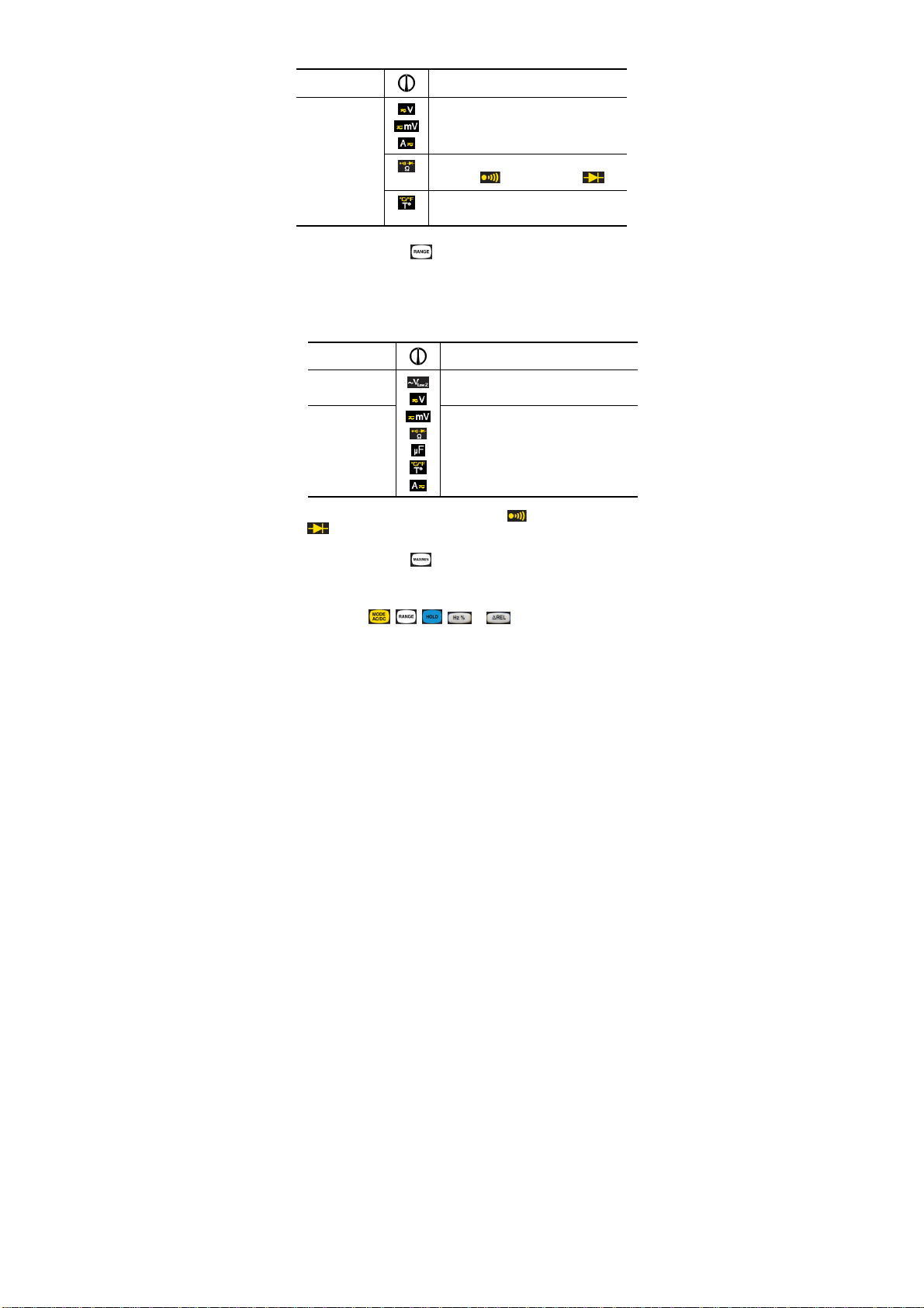
3.2 FONCTIONS DES TOUCHES
Les fonctions des touches , , , , et
sont accessibles par appuis successifs courts ou long. Chaque
appui est validé par un signal sonore.
3.2.1 Touche
Cette touche permet de sélectionner la nature et le mode
d’affichage des mesures ainsi que de désactiver l’arrêt
automatique de l’appareil, au démarrage, en combinaison avec
le commutateur. Un appui maintenu lors du démarrage en
tournant le commutateur de vers n’importe quelle position
désactive l’arrêt automatique. Le symbole n’est pas affiché.
Par défaut, l’arrêt automatique est activé, le symbole est
affiché.
Remarque : le mode DC est activé par défaut.
18 - 138
Page 19
Français
: AC
de sélectionner les modes test de
d’afficher la température en degré
Chaque appui…
Court
de changer la nature de la mesure
ou DC.
continuité ou test de diode .
Celsius (°C) ou en degré Fahrenheit (°F).
… permet
3.2.2 Touche
Cette touche permet de choisir manuellement un calibre de
mesure. Le calibre définit l’étendue de mesure maximale que
l’appareil peut effectuer.
Remarque : le mode Auto-range est activé par défaut.
Chaque appui …
court
Long
(> 2 sec)
Remarque : les modes test de continuité et test de diode
ne sont pas Auto-range.
de changer manuellement le calibre
de mesure (étendue et résolution).
de revenir en mode Auto-range.
… permet
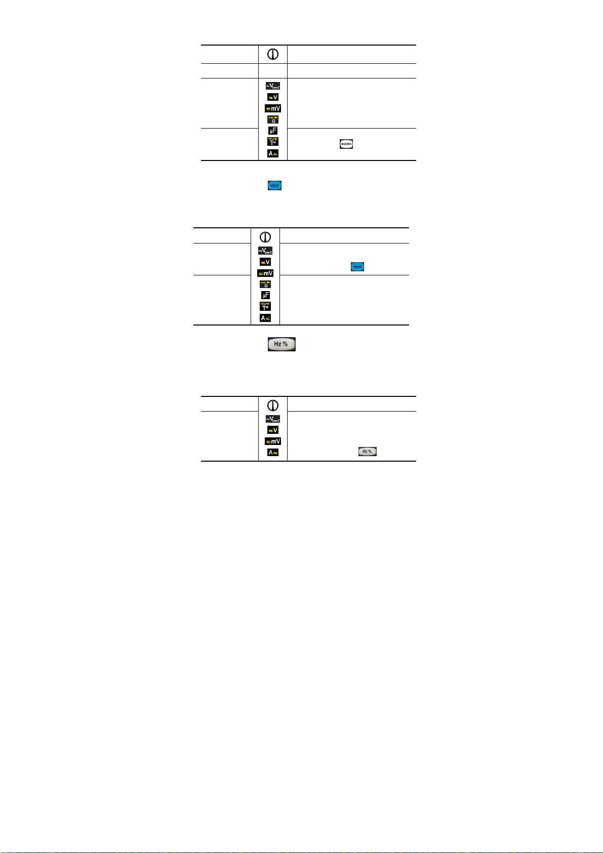
3.2.3
Cette touche permet la mémorisation et l’affichage
successivement des valeurs TRMS courante, maximale et
minimale.
Les touches , , , et , sont inactives en
mode MAX/MIN.
Le mode AUTO est désactivé.
19 - 138
Touche
Page 20
Chaque appui …
1er appui court activer la mémorisation MAX/MIN.
court
Long
(> 2 sec)
à chaque appui, de visualiser
successivement la valeur MAX, MIN
et courante.
Remarque : la grandeur MAX est
affichée par défaut.
sortir du mode .
… permet de
3.2.4 Touche
Cette touche permet de maintenir l’affichage de la valeur
mesurée, ainsi que d’activer / désactiver le rétro-éclairage de
l’écran.
Chaque appui …
court
long
(> 2 sec)
de maintenir l’affichage de la
valeur mesurée ;
de sortir du mode .
d’activer ou de désactiver le rétroéclairage de l’écran.
Nota : le rétro-éclairage s’éteint au
bout de 10 secondes .
… permet
Français
court
Touche
d’afficher la valeur de la
fréquence,
d’afficher la valeur du rapport
cyclique (Duty Cycle),
de sortir du mode
… permet
20 - 138
3.2.5
Cette touche permet d’afficher la valeur de la fréquence du
signal alternatif mesuré, ainsi que le rapport cyclique (Duty
Cycle).
Elle est inactive en mode DC.
Chaque appui …
Page 21
Français
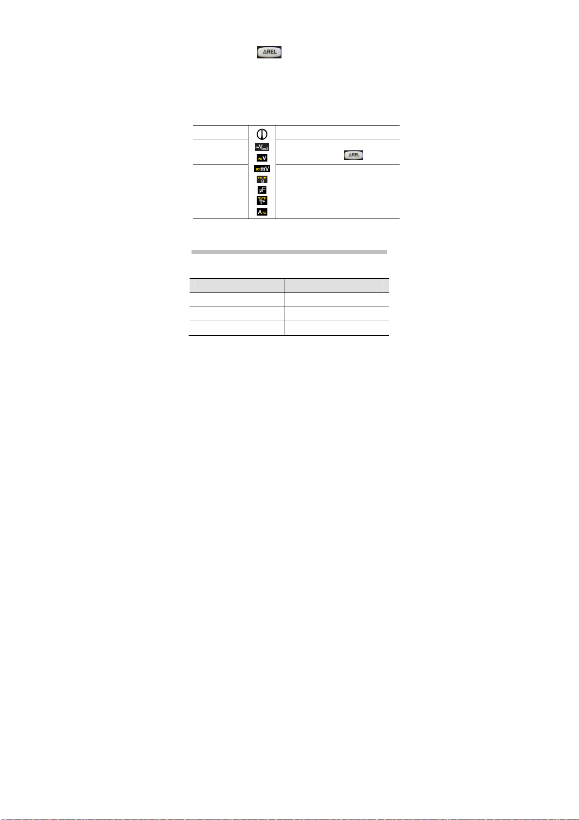
3.2.6
Cette touche permet d’afficher la valeur relative à partir d’une
référence mémorisée lors de l’appui sur la touche.
Par exemple, si la valeur mémorisée lors de l’appui sur la
touche = 10 V, la valeur courante étant 11,5 V, l’affichage en
mode relatif sera de 11,5 – 10 = 1,5 V.
Nota : le mode Autorange est désactivé.
Chaque appui …
Touche
court
long
(> 2 sec)
d’afficher la valeur relative;
de sortir du mode .
de désactiver l’Arrêt automatique.
… permet
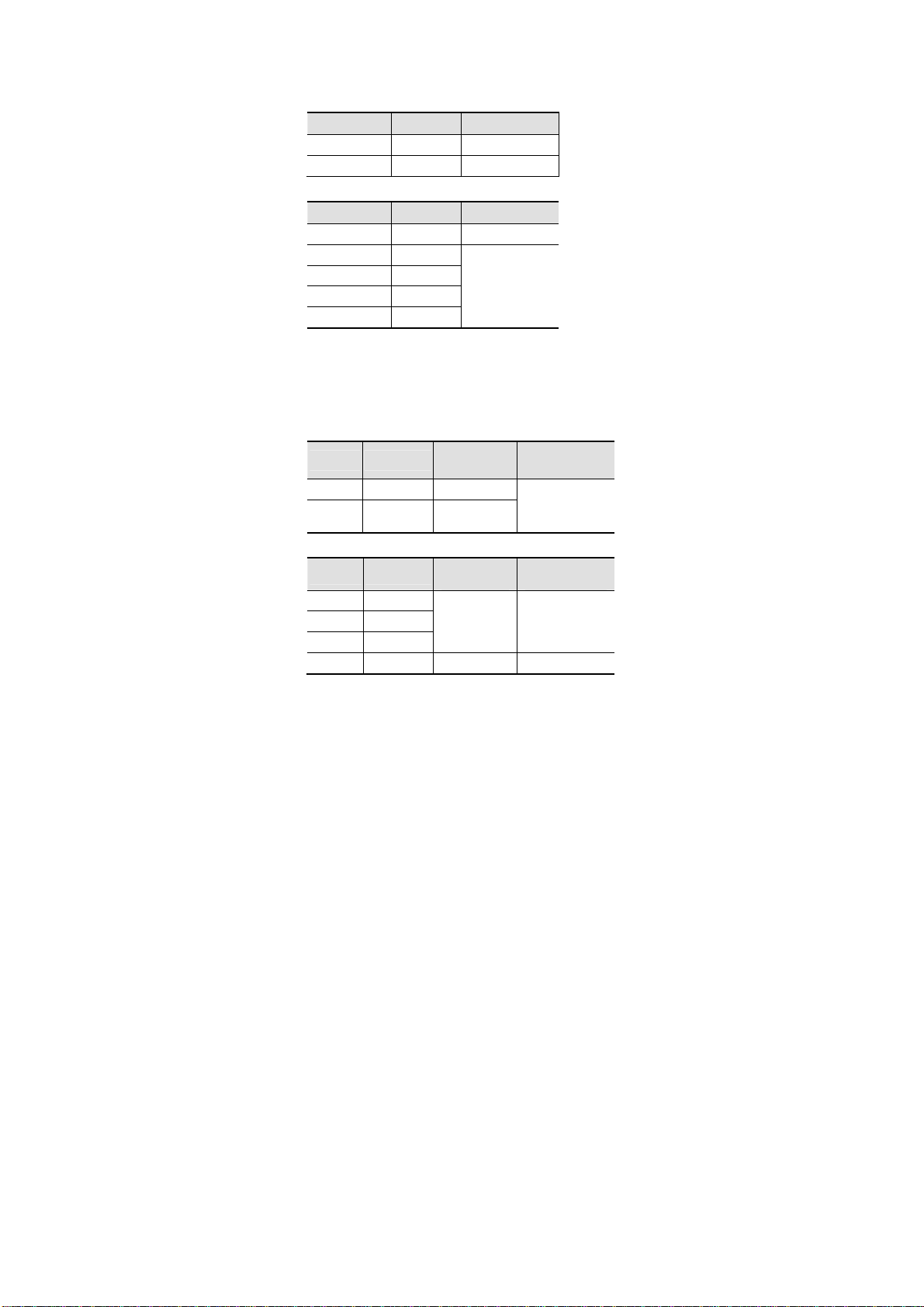
4. CARACTÉRISTIQUES
4.1 CONDITIONS DE RÉFÉRENCE
Grandeurs d’influence Conditions de référence
Température : 23 °C ± 2 °C
Humidité relative : 45 % à 75 %
Tension d’alimentation : 8,5 V ± 0,5 V
4.2 CARACTÉRISTIQUES AUX CONDITIONS DE
RÉFÉRENCE
L’incertitude est exprimée en x % de la lecture + y point(s), de
10% à 100% de chaque gamme de mesure.
21 - 138
Page 22
4.2.1 Tensions continues
Français
L’impédance d’entrée est de 10MΩ.
mV DC
Gamme Résolution
60 mV 0,01 mV 1 % + 12 pts
600 mV 0,1 mV 0,6 % + 2 pts
V DC
Gamme Résolution
600 mV 0,1 mV 0,6 % + 2 pts
6 V 0,001 V
60 V 0,01 V
600 V 0,1 V
1000 V * 1 V
Incertitude (±)
Incertitude (±)
0,2 % + 2 pts
* En application des règles de sécurité, le calibre 1000V est
limité à 600V.
4.2.2 Tensions alternatives
L’impédance d’entrée est de 10 MΩ.
mV AC True RMS
Gamme Résolution
60 mV 0,01 mV 1 % + 12 pts 1 % + 12 pts
600 mV 0,1 mV
V AC True RMS
Gamme Résolution
6 V 0,001 V
60 V 0,01 V
600 V 0,1 V
1000 V * 1 V
Incertitude (±)
40 Hz à 60 Hz
1 % + 3 pts
Incertitude (±)
40 Hz à 60 Hz
1 % + 3 pts
2 % + 3 pts 2,5 % + 3 pts
* En application des règles de sécurité, le calibre 1000V est
limité à 600V.
Incertitude (±)
60 Hz à 1 kHz
2 % + 3 pts
Incertitude (±)
60 Hz à 1 kHz
2 % + 3 pts
22 - 138
Page 23
Français
4.2.3 Tensions alternatives en basse impédance
(V AC LowZ True RMS)
L’impédance d’entrée est de 270kΩ.
Une basse impédance d’entrée permet de s’affranchir des
tensions parasites dues au réseau d’alimentation, et de
mesurer une tension alternative en minimisant les erreurs.
Gamme Résolution
6 V 0,001 V
60 V 0,01 V
600 V 0,1 V
1000 V * 1 V
Incertitude (±)
40 Hz à 60 Hz
2 % + 1 pt
* En application des règles de sécurité, le calibre 1000V est
limité à 600V.
4.2.4 Fréquence (V AC ou A AC)
Gamme Résolution
10 à 3000 Hz 0,01 Hz 0,5 % 15 V RMS
Incertitude (±)
Sensibilité
4.2.5 Duty Cycle
Gamme Résolution
0,1 à 99,9 % 0,1 % 1,2 % + 2 pts 5 Hz à 150 kHz
Incertitude (±)
Fréquence
4.2.6 Résistance
Gamme Résolution
600 Ω 0,1 Ω 2 % + 2 pts
6 kΩ 0,001 kΩ
60 kΩ 0,01 kΩ
600 kΩ 0,1 kΩ
6 MΩ 0,001 MΩ
60 MΩ 0,01 MΩ 0,5 % + 20 pts
23 - 138
0,3 % + 4 pts
Incertitude
(±)
Page 24
4.2.7 Test de continuité
Français
Gamme Résolution Incertitude
600 Ω 0,1 Ω
Signal sonore
déclenché
< 100 Ω ± 3 Ω
Courant
de mesure
< 0,35 mA
4.2.8 Test de diode
Gamme Résolution
2,8 V 0,001 V 1 % + 2 pts
Incertitude
(±)
Tension en circuit
ouvert
< 2,8 V < 0,9 mA
Courant
de mesure
4.2.9 Capacité
Gamme Résolution
40 nF 0,01 nF
400 nF 0,1 nF
4 µF 0,001 µF
40 µF 0,01 µF
400 µF 0,1 µF
1000 µF 1 µF 5 % + 5 pts
Incertitude (±)
3,5 % + 4 pts
4.2.10 Température (thermocouple de type K)
L’incertitude est donnée sans le thermocouple K.
Gamme Résolution
- 20 à 760 °C 1°C
- 4 à 1400 °F 1°F
Incertitude (±)
2 % + 5°C
2 % + 9°F
4.2.11 Max/Min
Temps de capture : 400 ms
Ajoutez une incertitude de ± (0,5 % + 2 pts) à l’incertitude de la
fonction et de la gamme utilisées.
24 - 138
Page 25

Français
4.2.12 Courants continus (10 A DC)
Gamme Résolution
6 A 0,001 A
10 A* 0,01 A
Incertitude (±)
1,5 % + 3 pts
Protection
Fusible rapide
F10 A/600 V/50 kA
6,3x32
*15 A pendant 60 secondes maximum.
4.2.13 Courants alternatifs (10 A AC)
Gamme Résolution
6 A 0,001 A
10 A* 0,01 A
Incertitude (±)
40 Hz à 1 kHz
2 % + 3 pts
*15 A pendant 60 secondes maximum.
Protection
Fusible rapide
F10 A/600 V/50 kA
6,3x32
4.3 CONDITIONS D’ENVIRONNEMENT
Conditions d’environnement en utilisation en stockage
Température : 0 °C à +50 °C -20 °C à +70 °C
Humidité relative (HR) : 90 % à 40 °C 50 % à 60 °C
4.4 CARACTÉRISTIQUES CONSTRUCTIVES
Dimension : H 155 x L 75 x P 55 mm
Masse : 320 g (avec la pile et le fusible)
Bargraphe : 61 segments, vitesse de rafraîchissement 30ms
Acquisition
mesure :
3 fois par seconde
4.5 ALIMENTATION
Alimentation : Pile 9 V LF22/6LR61
Autonomie : > 100 heures à température ambiante
Délai d’auto extinction : Après 15 minutes de non utilisation
25 - 138
Page 26
Français
4.6 CONFORMITÉS AUX NORMES INTERNATIONALES
Application des règles de sécurité selon la
Sécurité électrique :
norme EN 61010-1-Ed.2 : 2001.
600V CAT IV.
Degré de pollution 2. Double isolation.
Compatibilité
électromagnétique :
Résistance
mécanique :
Degré de protection
de l'enveloppe :
Conforme à la norme EN 61326/A2 : 2001
Milieu résidentiel
Chute libre : 1 m (selon la norme
IEC 68-2-32)
IP54 selon EN 60529
4.7 VARIATIONS DANS LE DOMAINE D’UTILISATION
Grandeur d’influence Plage d’influence Influence
Température 0°C à + 50°C
Fréquence 1 à 3 kHz
V AC : 0,5%L/10°C
mV DC : 0,5%L/10°C
Ω (R>20 MΩ) :
0,5%L/10°C
µF (C>50 µF) :
5%L/10°C
V AC : 10%L + 1pt
5. MAINTENANCE
Pour la maintenance, utilisez seulement les pièces de rechange
qui ont été spécifiées.
5.1 NETTOYAGE
Déconnectez tout cordon de l’appareil et positionnez le
commutateur sur .
Utilisez un chiffon doux, légèrement imbibé d’eau
savonneuse. Rincez avec un chiffon humide.
Séchez parfaitement avec un chiffon sec ou de l’air pulsé
avant toute nouvelle utilisation.
26 - 138
Page 27

Français
5.2 REMPLACEMENT DE LA PILE
Le symbole indique que la pile est usée et qu’elle doit être
changée. Quand ce symbole apparaît sur l’afficheur, l’appareil
fonctionne encore quelques minutes puis il s’éteint.
Pour remplacer la pile, procédez comme suit :
34. Positionnez le commutateur sur ;
35. Déconnectez les cordons de mesure des bornes
d’entrées ;
36. A l’aide d’un tournevis, dévissez les quatre vis de la
trappe d’accès à la pile située à l’arrière du boîtier (voir §
2.1) ;
37. Remplacez la pile défectueuse (voir § 2.1) ;
38. Revissez la trappe au boîtier. Remettez en place la
béquille.
5.3 REMPLACEMENT DU FUSIBLE
Pour remplacer le fusible, procédez comme suit :
39. Suivez les étapes 1. à 3. de la procédure décrite ci-
dessus (§ 5.2) ;
40. Retirez le fusible défectueux à l’aide d’un tournevis ;
41. Placez un nouveau fusible de caractéristiques identiques
puis revissez la trappe au boîtier.
5.4 VÉRIFICATION MÉTROLOGIQUE
Comme tous les appareils de mesure ou d’essai, une
vérification périodique est nécessaire.
Nous vous conseillons une vérification annuelle de cet appareil.
Pour les vérifications et étalonnages, adressez-vous à nos
laboratoires de métrologie accrédités COFRAC ou aux centres
techniques MANUMESURE.
Renseignements et coordonnées sur demande :
Tél. : 02 31 64 51 43 Fax : 02 31 64 51 09
27 - 138
Page 28

Français
5.5 RÉPARATION
Pour les réparations sous garantie et hors garantie, contactez
votre agence commerciale CHAUVIN-ARNOUX la plus proche
ou votre centre technique régional Manumesure, qui établira un
dossier de retour et vous communiquera la procédure à suivre.
Coordonnées disponibles sur notre site : http://www.chauvin-
arnoux.com ou par téléphone aux numéros suivants : 02 31 64
51 43 (centre technique Manumesure), 01 44 85 44 85
(Chauvin-Arnoux).
Pour les réparations hors de France métropolitaine, sous
garantie et hors garantie, retournez l’appareil à votre agence
Chauvin-Arnoux locale ou à votre distributeur.
6. GARANTIE
Notre garantie s’exerce, sauf stipulation expresse, pendant
douze mois après la date de mise à disposition du matériel.
Extrait de nos Conditions Générales de Vente, communiquées
sur demande.
La garantie ne s’applique pas suite à :
Une utilisation inappropriée de l’équipement ou à une
utilisation avec un matériel incompatible ;
Des modifications apportées à l’équipement sans
l’autorisation explicite du service technique du fabricant ;
Des travaux effectués sur l’appareil par une personne non
agréée par le fabricant ;
Une adaptation à une application particulière, non prévue par
la définition du matériel ou non indiquée dans la notice
fonctionnement ;
Des dommages dus à des chocs, chutes ou inondations.
28 - 138
Page 29

Français
7. POUR COMMANDER
Le C.A 5233
Le multimètre est livré avec :
• 1 paire de cordons pointe de touche, rouge et noir
• 1 pile 9 V alcaline
• 1 sonde de température (thermocouple type K)
• 1 adaptateur pour capteur de température type K
• la notice de fonctionnement
C.A 5233
P01196733
29 - 138
Page 30

English
PRECAUTIONS FOR USE
This device complies with safety standard IEC-61010-1
(Ed 2–2001) for voltages up to 600V in category IV, at an
altitude below 2000m, indoors, with a pollution level of not more
than 2.
Failure to observe the safety instructions may cause an electric
shock, fire, explosion, or destruction of the instrument and of
the installations.
Do not use the instrument in an explosive atmosphere or in
the presence of flammable gases or fumes.
Do not use the instrument on networks of which the voltage
or category exceeds those mentioned.
Do not exceed the rated maximum voltages and currents
between terminals or with respect to earth.
Do not use the instrument if it appears to be damaged,
incomplete, or not properly closed.
Before each use, check the condition of the insulation on the
leads, housing, and accessories. Any element of which the
insulation is deteriorated (even partially) must be set aside
for repair or scrapped.
Use leads and accessories rated for voltages and categories
at least equal to those of the instrument.
Observe the environmental conditions of use.
Do not modify the instrument and do not replace components
with "equivalents". Repairs and adjustments must be done by
approved qualified personnel.
Replace the battery as soon as the symbol appears on
the display unit. Disconnect all leads before opening the
battery compartment cover.
Use personal protective equipment when conditions require.
Keep your hands away from the unused terminals of the
instrument.
When handling probes or contact tips, keep your fingers
behind the guards.
30 - 138
Page 31

English
MEASUREMENT CATEGORIES
Definitions of the measurement categories according to standard IEC
61010-1:
CAT I: Circuits not directly connected to the network and specially
protected.
Example: protected electronic circuits.
CAT II: Circuits directly connected to the low-voltage installation.
Example: power supply to household electrical appliances and
portable tools.
CAT III: Power supply circuits in the installation of the building.
Example: distribution panel, circuit-breakers, fixed industrial
machines or devices.
CAT IV: Circuits supplying the low-voltage installation of the building.
Example: power lines, meters, and protection devices.
Français ....................................................................................... 2
Deutsch ........................................................................................ 57
Italiano .......................................................................................... 84
Español ........................................................................................ 111
31 - 138
Page 32

Thank you for purchasing a C.A. 5233 multimeter.
For best results from your device:
Read this user manual attentively;
Observe the precautions for its use.
Meaning of the symbols used on the instrument:
Risk of danger. The operator agrees to refer to these
instructions whenever this danger symbol appears.
Fuse.
9V battery.
The CE marking indicates compliance with European
directives.
Double or reinforced insulation.
Selective sorting of wastes for the recycling of electrical
and electronic equipment within the European Union.In
conformity with directive DEEE 2002/96/EC: this equipment
must not be treated as household waste.
AC – Alternating current.
AC or DC – Alternating or direct current.
Earth.
English
32 - 138
Page 33

English
CONTENTS
1. PRÉSENTATION ........................................................................ 34
1.1 THE DISPLAY UNIT .................................................................... 35
1.2 THE KEYS .................................................................................... 37
1.3 THE SWITCH ............................................................................... 38
1.4 THE TERMINALS ........................................................................ 39
2. USE ............................................................................................. 39
2.1 FIRST USE ................................................................................... 39
2.2 POWERING UP THE MULTIMETER ......................................... 40
2.3 POWERING DOWN THE MULTIMETER .................................. 40
2.4 THE PROP ................................................................................... 41
3. FUNCTIONS ................................................................................ 42
3.1 FUNCTIONS OF THE SWITCH.................................................. 42
3.2 FUNCTIONS OF THE KEYS ...................................................... 46
4. CHARACTERISTICS .................................................................. 49
4.1 REFERENCE CONDITIONS ...................................................... 49
4.2 CHARACTERISTICS AT THE REFERENCE CONDITIONS ... 49
4.3 ENVIRONMENTAL CONDITIONS ............................................. 53
4.4 CHARACTERISTICS OF CONSTRUCTION ............................. 53
4.5 POWER SUPPLY ........................................................................ 53
4.6 COMPLIANCE WITH INTERNATIONAL STANDARDS ................ 54
4.7 VARIATIONS IN DOMAIN OF USE ............................................. 54
5. MAINTENANCE .......................................................................... 54
5.1 CLEANING ................................................................................... 54
5.2 REPLACING THE BATTERY ..................................................... 55
5.3 REPLACING THE FUSE ............................................................. 55
5.4 METROLOGICAL CHECK .......................................................... 55
5.5 REPAIR ........................................................................................ 55
6. WARRANTY ................................................................................ 56
7. TO ORDER .................................................................................. 56
33 - 138
Page 34

English
NCV detection zone
1. PRÉSENTATION
The C.A 5233 is a TRMS digital multimeter, specially designed
to combine in a single instrument the various functions and
measurements of the following electrical quantities:
AC voltmeter with low input impedance (voltage
measurements in the fields of electricity and electrical
engineering);
AC or DC voltmeter with high input impedance (voltage
measurements in the field of electronics);
Measurement of frequency and duty cycle;
Ohmmeter;
Continuity test with buzzer;
Diode test;
Ammeter;
Capacitance meter;
Thermometer in °C or °F by measurement and linearis ation
of the voltage across the terminals of a type K thermocouple;
Contact-free detection of presence of network voltage (NCV
function, presence of phase).
Figure 1 : the C.A 5233 multimeter
1
2
3
4
34 - 138
Page 35

English
1
2
4
Item
1 Display unit 1.1
2 Function keys 1.2
3 Switch 1.3
4 Terminals 1.4
Designation See §
1.1 THE DISPLAY UNIT
The display unit allows :
An analog display of the parameter measured, in the form of
a bargraph, associated with a 6,000-point digital display.
Comfortable reading of the information thanks to the
backlighting of the screen.
7 6 8 5
Figure 2 : the display
35 - 138
Page 36

English
Item
Function See §
1 Bargraph
2 Display (values and units of measurement) 3.1
3 Nature of the measurement (AC or DC) 3.2.1
4 Automatic measurement range selection mode 3.2.2
5 Low battery indicator 5.2
6 Audible continuity test
Diode test
7 Display of the modes selected 1.2
8 Non-Permanent Mode : automatic switching off
of the device activated
1.1.1 The symbols on the display unit
The display unit uses the following symbols :
Symbol Designation
AC
Alternating current
DC
Direct current
AUTO
HOLD
Automatic change of range (see § 1.1.3)
Storage and display of stored values
MAX
Maximum RMS value
MIN
Minimum RMS value
REL
Relative value
O.L
Overshoot of measurement capabilities (see §1.1.2)
V
Volt
Hz
Hertz
%
Duty Cycle
F
Farad
°C
Degrees Celsius
°F
Degrees Fahrenheit
A
Ampere
36 - 138
3.1.3
3.1.4
3.2.1
Page 37

English
Permanent Mode (automtic switching off
Ω
Ohm
n
Prefix, nano-
µ
Prefix, micro-
m
Prefix, milli-
k
Prefix, kilo-
M
Prefix, MegaAudible continuity test
Diode test
Non-
activated)
Low battery indicator
1.1.2 Overshoot of measurement capabilities
(O.L.)
The O.L. (Over Load) symbol is displayed when the signal
measured exceeds the range of the device.
1.1.3 Automatic change of measurement range
(Autorange)
The AUTO symbol on the display unit indicates that the
instrument automatically changes the measurement range to
make the measurement. You can change the range manually
by pressing (see § 3.2.2).
1.2 THE KEYS
The keypad has six keys: , , , , et .
Here are the keys of the keypad.
1 2 3 4
5 6
Figure 3 : the keys on the keypad
37 - 138
Page 38

2
9
English
Item
1 Selection of the type of measurement (AC or
DC), , °C , °F or . Activation or de-
Function See §
3.2.1
activation of the automatic switching off of the
device at start-up.
2 Manual selection of the measurement range. 3.2.2
3 Activation or de-activation of the MAX/MIN mode. 0
4 Hold of display of the measured value.
Activation or de-activation of the blue back-
lighting of the screen ( ) (press > 2s).
5 Frequency and duty cycle measurement in V AC
and A AC
3.2.5
6 Measurement of the relative value 3.2.6
1.3 THE SWITCH
The switch has seven positions. The functions are described in
the table below :
4 5 6
3
1
0
7
8
Figure 4 : the switch
Item Function See §
1 OFF mode – Powers down the multimeter 2.3
2 AC voltage measurement at low input
impedance (V
LowZ
)
3.1.1
38 - 138
Page 39

English
3 AC or DC voltage measurement (V) 3.1.1
4 AC or DC voltage measurement (mV) 3.1.1
5 Resistance measurement
Continuity test
Diode test
6 Capacitance measurement 3.1.5
7 Temperature measurement in °C or °F 3.1.6
8 AC or DC current measurement 3.1.7
9 NVC (Non Contact Voltage) + Partial OFF
mode of the multimeter (NCV function active)
1.4 THE TERMINALS
The terminals are used as follows :
1 2 3
3.1.2
3.1.3
3.1.4
3.1.8
Figure 5 : the terminals
Item Function
1 Current measurement terminal (10 A)
2 Cold point terminal (COM)
3 Hot point terminal (+)
2. USE
2.1 FIRST USE
Insert the battery provided with the instrument as follows:
39 - 138
Page 40

1. Using a screwdriver, unscrew the four screws (a, b, c, and
c
English
d) holding the cover (item 1) on the back of the housing;
2. Place the battery in its compartment (item 2); watch out
for the polarity;
3. Screw the cover back onto the housing. Put the stand
back in place.
a
1
b
d
2
Figure 6 : access to the battery
2.2 POWERING UP THE MULTIMETER
The switch is set to
choice. All segments of the display unit light for a few seconds
(see figure 2, § 1.1) the screen corresponding to the chosen
function then appears. The multimeter is now ready for
measurements.
. Turn the switch to the function of your
2.3 POWERING DOWN THE MULTIMETER
The multimeter can be switched off manually, by setting the
switch to
unused for 15 minutes. At the 14th minute, 5 beeps warn that
the multimeter is about to be switched off. To reactivate the
instrument, press any key on the keypad.
Nota : the position does not completely switch off the
multimeter; it remains active for contact-free detection of the
presence of the network voltage (NCV).
, it will also switch itself off automatically if left
40 - 138
Page 41

English
2.4 THE PROP
The prop can be placed in either of two positions according to
how it is to be used: to suspend the multimeter from a hook
(position 1) or to stand it in an inclined position on a support
(position 2). To change the position of the prop, proceed as
follows:
Positon 1 : raise the stand Position 2 : lower the stand
Hooking
zone for
multi-position
attachment
accessory
41 - 138
Page 42

3. FUNCTIONS
3.1 FUNCTIONS OF THE SWITCH
To access to the functions of the switch, set the switch to
, , , , , , or .
3.1.1 Voltage measurement
The instrument measures :
the AC voltage at low input impedance (VLowZ);
direct voltages (DC);
alternating voltages (AC).
To measure a voltage, proceed as follows:
1. Set the switch to , or ; when set to the
device is in AC mode only ;
2. For or ,select AC or DC by pressing . As
default, the device is in DC mode. Depending on your
selection, the screen displays AC or DC.
3. Connect the black lead to the COM terminal and the red
lead to “+”;
4. Place the contact tips on the terminals of the circuit to be
measured;
English
The measured voltage is displayed on screen.
3.1.2 Resistance measurement
Attention : all resistance measurements must be made in the
absence of any voltage.
To measure a resistance, proceed as follows:
1. Set the switch to ;
2. Connect the black lead to the COM terminal and the red
lead to “+”;
3. Place the contact tips on the terminals of the component
or circuit to be measured;
42 - 138
Page 43

English
The measured resistance is displayed on screen.
3.1.3 Continuity tes with buzzer
Attention : all continuity measurements must be made in the
absence of any voltage.
To test electrical continuity, proceed as follows :
1. Set the switch to ;
2. Press . The symbol is displayed ;
3. Connect the black lead to the COM terminal and the red
lead to “+”;
4. Place the contact tips on the terminals of the component
or circuit to be tested;
The buzzer indicates continuity; the measured resistance is
displayed on screen.
3.1.4 Diode test
Attention : all diode test measurements must be made in a
power-off condition.
To test a diode, proceed as follows :
1. Set the switch to ;
43 - 138
Page 44

Forward direction
English
2. Press twice. The symbol is displayed ;
3. Connect the black lead to the COM terminal and the red
lead to “+”;
4. Place the contact tips on the terminals of the component;
The voltage across the terminals of the component is displayed
on screen.
3.1.5 Capacitance measurement
Attention : all capacitance measurements must be made in a
power-off condition. Observe the connection polarity (+ to the
red terminal, - to the black terminal)
To measure the capacitance, proceed as follows :
1. Make sure that the capacitor to be measured is
discharged;
2. Set the switch to ;
3. Connect the black lead to the COM terminal and the red
lead to “+”;
4.
Place the contact tips on the terminals of the component;
The measured capacitance is displayed on screen.
44 - 138
Page 45

English
3.1.6 Temperature measurement
To measure the temperature, proceed as follows :
1. Set the switch to ;
2.
Press
°F) ;
Remark : the default is °C.
3. Connect the temperature probe adapter (item 1) to the
COM and “+” terminals, observing the polarity;
4. Connect the temperature probe (item 2) to the adapter,
observing the polarity;
Nota : if the probe is disconnected or open-circuit, the display
unit indicates OL.
to select the temperature unit and scale (°C or
The thermocouple temperature indication is displayed on
screen.
3.1.7 Current measurement
1. Set the switch to ;
2. Select AC or DC by pressing . As default, the device
is in DC mode. According to your selection, the screen
displays DC or AC ;
3. Connect the black lead to the COM terminal and the red
lead to “10A” ;
4. Connect the multimeter in series in the circuit.
45 - 138
Page 46

English
The measured current is displayed on screen.
3.1.8 Non Contact Voltage NCV
1. Set the switch to ;
2. Move the C.A 5231 (NCV detection zone) close to the
potentially live conductor(s) (presence of phase);
3.
If a network voltage of 230V is present (Europe model),
the back-lighting lights red; otherwise, it remains off.
3.2 FUNCTIONS OF THE KEYS
The functions of the , , , , and keys
can be accessed by successive short or long presses. Each
press is confirmed by an audible signal.
3.2.1 The key
This key is used to select the type of measurement and the
display mode to deactivate the automatic switching off of the
device, at start-up, in combination with the switch. A long press
during start-up, while turning the switch to any position,
deactivates automatic switching off. The symbol is not
displayed. As default, automatic switching off is activated and
the symbol is displayed.
Remark : the Dc mode is activated as default.
46 - 138
Page 47

English
Change the nature of the measurement
or diode
To display the temperature in degrees
Each press of
this length…
short
AC or DC.
Select the continuity test
test mode.
Celsius (°C) or in degrees Fahrenheit (°F).
…serves to
3.2.2 The key
This key is used to choose a measurement range manually.
The range defines the maximum measurement span of which
the device is capable.
Remark : the Auto-range mode is activated as default.
Each press of
this length…
short
Long
(> 2 sec)
Remark : the continuity test and diode test modes are
not Auto-range.
To change the measurement range
manually (span and resolution).
To return to Auto-range mode.
…serves to
3.2.3 The key
This key is used to store and display, successively, the current,
maximum, and minimum TRMS values.
The , , , and , keys are inactive in the
MAX/MIN mode.
The AUTO mode is deactivated.
47 - 138
Page 48

Each press of
this length…
1st short activate MAX/MIN storage.
short
Long
(> 2 sec)
at each press, to view in turn the
MAX, MIN, and current value.
Remark: the MAX value is displayed
as default.
Exit from the mode.
…serves to
English
3.2.4 The key
This key is used to hold the display of the measured value, and
to activate/deactivate the backlighting of the screen.
Each press of
this length…
court
long
(> 2 sec)
To hold the display of the
measured value ;
To exit from the mode.
to activate/deactivate the backlighting
of the screen.
Note: the backlighting is switched off
at the end of 10 seconds.
…serves to
3.2.5 The key
This key is used to display the frequency of the AC signal
measured, along with the duty cycle.
It is inactive in DC mode.
Each press of
this length…
short
to display the frequency,
to display the duty cycle,
to exit from the mode
…serves to
48 - 138
Page 49

English
3.2.6
This key is used to display the value relative to a reference
stored when the key was pressed.
For example, if the value stored when the key was pressed =
10V and the current value is 11.5V, the display in relative mode
will be 11.5 - 10 = 1.5V.
Note: the Autorange mode is deactivated.
Each press of
The key
this length…
short
long
(> 2 sec)
to display the relative value ;
to exit from the mode.
To deactivate automatic switching off.
…serves to
4. CHARACTERISTICS
4.1 REFERENCE CONDITIONS
Quantities of influence Reference conditions
Temperature : 23 °C ± 2 °C
Relative humidity : 45 % to 75 %
Supply voltage : 8,5 V ± 0,5 V
4.2 CHARACTERISTICS AT THE REFERENCE
CONDITIONS
The uncertainty is expressed in the form x% of the reading + y
counts, from 10% to 100% of each measurement range.
49 - 138
Page 50

4.2.1 Direct voltages
English
The input impedance is 10MΩ.
mV DC
Range Resolution
60 mV 0.01 mV 1 % + 12 cts
600 mV 0.1 mV 0,6 % + 2 cts
V DC
Range Resolution
600 mV 0.1 mV 0.6 % + 2 cts
6 V 0.001 V
60 V 0.01 V
600 V 0.1 V
1000 V * 1 V
Uncertainty (±)
Uncertainty (±)
0.2 % + 2 cts
* According to safety rules, 1000V range is limited to 600V.
4.2.2 Alternating voltages
The input impedance is 10 MΩ.
mV AC True RMS
Range Resolution
60 mV 0.01 mV 1 % + 12 cts 1 % + 12 cts
600 mV 0.1 mV
V AC True RMS
Range Resolution
6 V 0,001 V
60 V 0,01 V
600 V 0,1 V
1000 V * 1 V
Uncertainty (±)
40 Hz to 60 Hz
1 % + 3 cts
Uncertainty (±)
40 Hz to 60 Hz
1 % + 3 cts
2 % + 3 cts 2,5 % + 3 cts
* According to safety rules, 1000V range is limited to 600V.
Uncertainty (±)
60 Hz to 1 kHz
2 % + 3 cts
Uncertainty (±)
60 Hz to 1 kHz
2 % + 3 cts
50 - 138
Page 51
English
4.2.3 Alternating voltages at low impedance (V
AC LowZ True RMS)
The input impedance is 270kΩ.
A low input impedance serves to eliminate the effects of
interference voltages due to the supply network, and makes it
possible to measure an AC voltage with a minimum of error.
Range Resolution
6 V 0,001 V
60 V 0,01 V
600 V 0,1 V
1000 V * 1 V
Uncertainty (±)
40 Hz à 60 Hz
2 % + 1 ct
* According to safety rules, 1000V range is limited to 600V.
4.2.4 Frequency (V AC or A AC)
Range Resolution
10 to 3000 Hz 0.01 Hz 0.5 % 15 V RMS
Uncertainty (±)
Sensitivity
4.2.5 Duty Cycle
Range Resolution
0.1 to 99.9 % 0.1 % 1.2 % + 2 cts 5 Hz to 150 kHz
Uncertainty (±)
Frequency
4.2.6 Resistance
Range Resolution
600 Ω 0.1 Ω 2 % + 2 cts
6 kΩ 0.001 kΩ
60 kΩ 0.01 kΩ
600 kΩ 0.1 kΩ
6 MΩ 0.001 MΩ
60 MΩ 0.01 MΩ 0.5 % + 20 cts
51 - 138
Uncertainty (±)
0.3 % + 4 cts
Page 52

4.2.7 Continuity test
Range Resolution Uncertainty
Audible signal
600 Ω 0.1 Ω
triggered
< 100 Ω ± 3 Ω
Measurement
current
< 0.35 mA
4.2.8 Diode test
Range Resolution
2.8 V 0.001 V 1 % + 2 cts < 2.8 V < 0.9 mA
Uncertainty (±)
Open-circuit
voltage
Measurement current
4.2.9 Capacity
Range Resolution
40 nF 0.01 nF
400 nF 0.1 nF
4 µF 0.001 µF
40 µF 0.01 µF
400 µF 0.1 µF
1000 µF 1 µF 5 % + 5 cts
Uncertainty (±)
3.5 % + 4 cts
4.2.10 Temperature (type K thermocouple)
The uncertainty does not include the K thermocouple.
Range Resolution
- 20 to 760 °C 1°C
- 4 to 1400 °F 1°F
Uncertainty (±)
2 % + 5°C
2 % + 9°F
English
4.2.11 Max/Min
Capture time: 400 ms
Add an uncertainty of ± (0.5% + 2 pts) to the uncertainty of the
function and of the range used.
52 - 138
Page 53

English
4.2.12 DC current (10 A DC)
Range Resolution
6 A 0.001 A
10 A* 0.01 A
Uncertainty (±)
1.5 % + 3 cts
Protection
Fast-blow fuse
F10 A/600 V/50 kA
6.3x32
*15 A for a maximum of 60 seconds.
4.2.13 AC current (10 A AC)
Range Resolution
6 A 0.001 A
10 A* 0.01 A
Uncertainty (±)
40 Hz to 1 kHz
2 % + 3 cts
*15 A for a maximum of 60 seconds.
Protection
Fast-blow fuse
F10 A/600 V/50 kA
6.3x32
4.3 ENVIRONMENTAL CONDITIONS
Environmental conditions In use In storage
Temperature : 0 °C to +50 °C -20 °C to +70 °C
Relative humidity (HR) : 90 % at 40 °C 50 % at 60 ° C
4.4 CHARACTERISTICS OF CONSTRUCTION
Dimension : H 155 x W 75 x D 55 mm
Weight : 320 g (with the battery and the fuse)
Bargraph : 61 segments, refresh interval 30 ms
Measurement
acquisition:
3 times per second
4.5 POWER SUPPLY
Power supply : 9 V LF22/6LR61 battery
Battery life : > 100 hours at room temperature
Auomatic switching off
time :
53 - 138
15 minutes of non-use
Page 54

English
4.6 COMPLIANCE WITH INTERNATIONAL STANDARDS
Application of safety rules as per standard
Electrical safety :
EN-61010-1-Ed.2:2001.
1000V CAT-III - 600V CAT-IV.
Pollution level 2. Double insulation.
Electromagnetic
compatibility :
Mechanical
strength :
Degree of protection
of the housing :
Compliant with standard EN61326/A2:2001
Residential environment
Free fall: 1m (in accordance with standard
IEC-68-2-32)
IP54 as per EN 60529
4.7 VARIATIONS IN DOMAIN OF USE
Quantity of influence Range of influence
Temperature 0°C to + 50°C
Frequency 1 to 3 kHz
Influence
V AC : 0.5%L/10°C
mV DC : 0.5%L/10°C
Ω (R>20 MΩ) :
0.5%L/10°C
µF (C>50 µF) :
5%L/10°C
V AC : 10%L + 1ct
5. MAINTENANCE
For maintenance, use only the replacement parts specified.
5.1 CLEANING
Disconnect all leads from the instrument and set the switch
to .
Use a soft cloth, dampened with soapy water. Rinse with a
damp cloth.
Dry thoroughly with a dry cloth or forced air before using
again.
54 - 138
Page 55

English
5.2 REPLACING THE BATTERY
The symbol indicates that the battery is low and must be
changed. When this symbol appears on the display unit, the
instrument continues to operate for a few minutes, then
switches itself off.
To replace the battery, proceed as follows:
1. Set the switch to ;
2. Disconnect the measurement leads from the input
terminals;
3. using a screwdriver, unscrew the four screws of the
battery compartment cover on the back of the housing
(see 2.1) ;
4. Replace the old battery (see §2.1) ;
5. Screw the cover back onto the housing. Put the stand
back in place.
5.3 REPLACING THE FUSE
To replace the fuse, proceed as follows :
1. Follow the steps 1 to 3 of the procedure described above
(§ 5.2) ;
2. Remove the blown fuse using a screwdriver;
3. Insert an identical fuse, then screw the cover back onto
the housing.
5.4 METROLOGICAL CHECK
Like all measuring or testing devices, the instrument must be
checked regularly.
This instrument should be checked at least once a year. For
checks and calibrations, contact one of our accredited
metrology laboratories (information and contact details available
on request), at our Chauvin Arnoux subsidiary or the branch in
your country.
5.5 REPAIR
For all repairs before or after expiry of warranty, please return
the device to your distributor.
55 - 138
Page 56

English
6. WARRANTY
Except as otherwise stated, our warranty is valid for twelve
months starting from the date on which the equipment was sold.
Extract from our General Conditions of Sale provided on
request.
The warranty does not apply in the following cases:
Inappropriate use of the equipment or use with incompatible
equipment;
Modifications made to the equipment without the explicit
permission of the manufacturer’s technical staff;
Work done on the device by a person not approved by the
manufacturer;
Adaptation to a particular application not anticipated in the
definition of the equipment or not indicated in the user’s
manual;
Damage caused by shocks, falls, or floods.
7. TO ORDER
The C.A 5233
The multimeter is delivered with :
• 1 pair of leads, red and black
• 1 9V alkaline battery
• 1 temperature probe (type K thermocouple)
• 1 adapter for type K temperature probe
• 1 user manual
C.A 5233
P01196733
56 - 138
Page 57

Deutsch
BEDIENUNGSHINWEISE
Dieses Gerät entspricht der Sicherheitsnorm IEC-61010-1 (Ed
2–2001) bei Spannungen 600V KAT IV auf bis zu 2000 m Höhe
und in Innenräumen, bis zu einem Verschmutzungsgrad 2.
Die Sicherheitsanweisungen müssen unbedingt beachtet
werden, weil sonst Stoßspannung, Brand, Explosion oder
Zerstörung des Geräts und der Anlagen drohen.
Das Gerät darf nicht in explosibler Atmosphäre verwendet
werden, wo brennbare Stoffe in Form von Gasen und
Dämpfen vorhanden sind.
Verwenden Sie das Gerät niemals in höherwertigen
Spannungsnetzen und Überspannungskategorien als
angegeben!
Halten Sie sich an die max. zul. Nennspannungen und ströme zwischen den Buchsen und gegen Erde.
Benutzen Sie niemals ein Gerät, das beschädigt,
unvollständig oder schlecht geschlossen erscheint.
Prüfen Sie vor jedem Einsatz nach, ob die Isolierung der
Drähte, des Gehäuses und des Zubehörs einwandfrei ist.
Teile mit selbst teilweise beschädigter Isolierungen müssen
repariert oder entsorgt werden.
Verwenden Sie nur Drähte und Zubehör, das mindestens
den angegebenen Spannungen und
Überspannungskategorien des Geräts entspricht.
Achten Sie auf die Umweltdaten für den Gerätebetrieb.
Das Gerät darf nicht geändert und die einzelnen
Komponenten dürfen nicht durch Gleichartige ersetzt
werden. Reparatur- und Einstellarbeiten am Gerät dürfen nur
von befugten Fachleuten vorgenommen werden.
Die Batterien müssen sofort ausgetauscht werden, wenn das
Symbol " " aufleuchtet. Alle Leitungen abnehmen, bevor
man das Batteriefach öffnet.
Tragen Sie je nach Arbeitsbedingungen nötigenfalls
geeignete Schutzkleidung.
Die Hände müssen in möglichst großer Entfernung von den
unbesetzten Gerätebuchsen gehalten werden.
Die Hände müssen beim Umgang mit Sonden bzw.
Prüfspitzen immer hinter der Schutzvorkehrung liegen.
57 - 138
Page 58

Deutsch
MESSKATEGORIE
Definition der Messkategorien gemäß IEC 61010-1:
CAT I: Stromkreise, die nicht direkt mit dem Stromnetz verbunden
sind oder geschützt sind.
Beispiel: geschützte Stromkreise.
CAT II: Stromkreise an Niederspannungsanlagen.
Beispiel: Stromversorgung von Haushaltsgeräten oder
tragbaren Elektrowerkzeugen.
CAT III: Stromversorgungskreise innerhalb der Haus- oder
Gebäudeinstallation.
Beispiel: Verteiler, Leistungsschalter, fest installierte Maschinen
oder Industrieanlagen.
CAT IV: An der Quelle der Niederspannungsinstallation im Gebäude.
Beispiel: Haupktverteilung, Zähler und primärer
Überspannungsschutz.
Français ....................................................................................... 2
English ......................................................................................... 30
Italiano .......................................................................................... 84
Español ........................................................................................ 111
58 - 138
Page 59

Deutsch
Sie haben ein C.A. 5233 Multimeter erstanden, wir danken
Ihnen für Ihr Vertrauen.
Für die Erlangung eines optimalen Betriebsverhaltens Ihres
Gerätes:
Lesen Sie bitte diese Betriebsanleitung aufmerksam durch
und;
Beachten Sie bitte die Anwendungshinweise.
Bedeutung der Gerätesymbole:
Gefahr! Sobald dieses Gefahrenzeichen auftritt, ist der
Bediener verpflichtet, die Anleitung zu Rate zu ziehen.
Sicherung
Batterie-9V.
Die CE-Markierung bedeutet, dass das Gerät die
anwendbaren europäischen Richtlinien erfüllt.
Das Gerät ist schutzisoliert bzw. durch eine verstärkte
Isolierung geschützt.
Der durchgestrichene Mülleimer bedeutet, dass das
Produkt in der Europäischen Union gemäß der Richtlinie
WEEE 2002/96/EC einer Abfalltrennung zur
Wiederaufbereitung von Elektro- und Elektronik-Altgeräten
unterzogen werden muss.
AC – Wechselstrom
AC oder DC – Wechselstrom oder Gleichstrom
Erde.
59 - 138
Page 60

INHALT
1. VORSTELLUNG ................................. Erreur ! Signet non défini.
1.1 ANZEIGE ...................................................................................... 62
1.2 TASTEN ....................................................................................... 64
1.3 SCHALTER .................................................................................. 65
1.4 BUCHSEN .................................................................................... 66
2. VERWENDUNG .......................................................................... 67
2.1 ERSTE SCHRITTE ...................................................................... 67
2.2 MULTIMETER-INBETRIEBNAHME ........................................... 67
2.3 MULTIMETER ABSCHALTEN.................................................... 67
2.4 DER STANDBÜGEL .................................................................... 68
3. FUNKTIONEN ............................................................................. 69
3.1 DREHSCHALTERFUNKTIONEN ............................................... 69
3.2 TASTENFUNKTIONEN ............................................................... 73
4. EIGENSCHAFTEN ...................................................................... 76
4.1 REFERENZBEDINGUNGEN ...................................................... 76
4.2 EINGENSCHAFTEN ZU DEN REFERENZBEDINGUNGEN ... 76
4.3 UMWELTBEDINGUNGEN .......................................................... 80
4.4 ALLGEMEINE BAUDATEN ......................................................... 80
4.5 STROMVERSORGUNG ............................................................. 80
4.6 KONFORMITÄT MIT INTERNATIONALEN NORMEN .................. 81
4.7 SCHWANKUNGEN IM EINSATZBEREICH ................................ 81
5. WARTUNG .................................................................................. 81
5.1 REINIGUNG ................................................................................. 81
5.2 BATTERIEWECHSEL ................................................................. 82
5.3 ERSETZEN DER SICHERUNG ................................................. 82
5.4 MESSTECHNISCHE ÜBERPRÜFUNG ..................................... 82
5.5 REPARTUR.................................................................................. 82
6. GARANTIE .................................................................................. 83
7. BESTELLANGABEN .................................................................. 83
Deutsch
60 - 138
Page 61

Deutsch
Erfassungsbereich NCV
1. VORSTELLUNG
Das C.A. 5233 ist ein TRMS Digital-Multimeter, das als
Mehrzweckgerät verschiedene Funktionen und Messungen für
folgende elektrische Größen bietet:
AC-Voltmeter für niedrige Eingangsimpedanz
(Spannungsmessen in Elektrik und Elektrotechnik);
AC- oder DC-Voltmeter bei hoher Eingangsimpedanz
(Spannungsmessen in Elektronik);
Frequenzmessung und Duty Cycle (Betriebszyklus);
Ohmmeter;
Durchgangsprüfung mit Summer;
Diodenprüfung;
Amperemeter;
Kapazität;
Thermometer in °C oder °F bei Messung oder Linearis ierung
der Lastspannung an den Buchsen eines Thermoelement
Type K;
Berührungsfreie Erfassung von Netzspannung (NCVFunktion Vorhandsein von Phasen).
Abb. 1 : Multimeter C.A 5233
61 - 138
1
2
3
4
Page 62

1
2
4
Nr. Bezeichnung Siehe Abs.
1 Anzeige 1.1
2 Funktionstasten 1.2
3 Drehschalter 1.3
4 Buchsen 1.4
Deutsch
1.1 ANZEIGE
Die Anzeige ermöglicht :
Eine Analog-Anzeige dank einer Balkenanzeige, sowie eine
Digitalanzeige mit 6000 Digits.
Ein bequemes Ablesen der Informationen dank der
Hintergrundbeleuchtung der Anzeige.
7 6 8 5
Abb. 2 : Anzeige
62 - 138
Page 63

Deutsch
Nr.
Funktion
1 Balkenanzeige
2 Anzeige (Werte und Messeinheiten) 3.1
3 Messart (AC oder DC) 3.2.1
4 Automatische Messbereichseinstellung 3.2.2
5 Anzeige bei geringem Batterieladestand 5.2
6 Akustische Durchgangsprüfung
Diodenprüfung
7 Anzeige des ausgewählten Modus 1.2
8 Nicht-Dauerbetriebmodus: Stromsparmodus
(autom. Abschalten des Gerätes) aktiviert
1.1.1 Anzeigesymbole
Folgende Anzeigesymbole werden verwendet:
Symbole Bezeichnung
AC
Wechselstrom
DC
Gleichstrom
AUTO
HOLD
Automatische Bereichseinstellung, (siehe Abs. 1.1.3)
Speicherung und Anzeige der gespeicherten Daten
MAX
Höchster RMS-Wert
MIN
Geringster RMS-Wert
REL
Relativwert
O.L
Überschreitung der Messkapazität (siehe Abs. 1.1.2)
V
Volt
Hz
Hertz
%
Duty Cycle (Betriebszyklus)
F
Farad
°C
Celsius
°F
Fahrenheit
Siehe
Abs. §
3.1.3
3.1.4
3.2.1
63 - 138
Page 64

Deutsch
A
Ampere
Ω
Ohm
n
Vorsilbe für „Nano“
µ
Vorsilbe für „Mikro“
m
Vorsilbe für „Milli-“
k
Vorsilbe für „Kilo-“
M
Vorsilbe für „Mega-“
Akustische Durchgangsprüfung
Diodenprüfung
Nicht-Dauerbetriebsmodus (Abschaltautomatik)
Anzeige bei geringem Batterieladestand
1.1.2 Überschreitung der Messkapazität (O.L)
Das Symbol O.L (Over Load) erscheint auf der Anzeige, wenn
das Messsignal die Messbereichkapazität des Gerätes
übersteigt.
1.1.3 Auto-Range-Modus (Autorange)
Das Symbol AUTO bedeutet, dass das Gerät den Messbereich
automatisch festlegt. Der Messbereich kann manuell mit
Drücken der Taste geändert werden (siehe Abs. 3.2.2).
1.2 TASTEN
Die Tastatur hat sechs Tasten: , , , , und
. Hier sehen Sie die Tastaturtasten:
1 2 3 4
5 6
Abb. 3 : Gerätetasten
64 - 138
Page 65

Deutsch
2
9
Nr.
1 Auswahl für die Messart (AC oder DC), ,
°C , °F oder . Aktivierung oder Deaktivierung
Funktion
Siehe
Abs.
3.2.1
der Abschaltautomatik des Gerätes beim Start.
2 Manuelle Auswahl des Messbereiches. 3.2.2
3 Aktivierung oder Deaktivierung des Modus
MAX/MIN
4 Hold-Modus des angezeigten Werts.
Aktivierung oder Deaktivierung der blauen
Hintergrundbeleuchtung der Anzeige ( )
(Drücken >2s)
5 Frequenzmessung und Duty Cycle Messung in V
AC und A AC
3.2.5
6 Messung der Relativwert 3.2.6
1.3 SCHALTER
Drehschalter mit neun Stellungen. Die Funktionen werden in
der Tabelle unten beschrieben :
4 5 6
3
1
0
0
7
8
Abb. 4 : Schalter
65 - 138
Page 66

Nr.
Funktion
1 OFF – Multimeter ausschalten 2.3
2 Messung von Wechselspannung in niedriger
Eingangsimpedanz (V
LowZ
)
3 Messen der AC- oder DC-Spannung (V) 3.1.1
4 Messen der AC- oder DC-Spannung (mV) 3.1.1
5 Messung des Widerstandes
Durchgangsprüfung
Diodenprüfung
6 Kapazitätsmessung 3.1.5
7 Temperaturmessung in °C oder °F 3.1.6
8 Stromstärke in AC oder DC 3.1.7
9 NCV (Non Contact Voltage) + tlw. OFF Modus
des Multimeters (eingeschaltete NCV-
Funktion)
1.4 BUCHSEN
Verwendung der einzelnen Buchsen:
1 2 3
Deutsch
Siehe
Abs.
3.1.1
3.1.2
3.1.3
3.1.4
3.1.8
Abb. 5 : Buchsen
Nr. Funktion
1 Buchse Stromstärke (10A)
2 Buchse Kaltpunkt (COM)
3 Buchse Heißpunkt (+)
66 - 138
Page 67

Deutsch
c
2. VERWENDUNG
2.1 ERSTE SCHRITTE
Legen Sie die mitgelieferte Batterie so ein:
1. Mit einem Schraubendreher die vier Schrauben a, b, c
und d des Batteriefachdeckels (Nr. 1) hinten am Gehäuse
lösen;
2. Die Batterie in das Gehäuse (Nr. 2) einlegen, Polarität
beachten.
3. Batteriefachdeckel wieder festschrauben. Legen Sie den
Standbügel wieder ein.
a
1
b
d
2
Abb. 6 : Batteriefach
2.2 MULTIMETER-INBETRIEBNAHME
Der Schalter steht auf
gewünschte Funktion. Kurz blinken alle Anzeigesegmente auf
(siehe Abb. 1.1), dann wird die gewählte Funktion angezeigt.
Das Gerät ist nun messbereit.
. Drehen Sie den Schalter auf die
2.3 MULTIMETER ABSCHALTEN
Das Multimeter wird manuell mit dem Drehschalter abgeschaltet
(Schalter auf , drehen), bzw. nach 15 Minuten Inaktivität
automatisch in abgeschaltet. Nach 14 Minuten warnen 5
Piepstöne vor der bevorstehenden Abschaltung des
Multimeters. Um das Gerät wieder zu aktiveren, betätigt man
eine beliebige Gerätetaste.
Anmerkung: Die Position schaltet das Multimeter nicht
völlig aus, es bleibt aktiv für die berührungsfreie Erkennung des
Vorhandenseins einer Netzspannung (NCV).
67 - 138
Page 68

Deutsch
2.4 DER STANDBÜGEL
Es gibt zwei Positionen für den Standbügel: Man kann das
Multimeter daran aufhängen (Position 1), und man kann es
schräg aufstellen (Position 2). Wechseln der Standbügelstellung
wie folgt:
Positon 1 : Legen Sie die
Standbügel nach oben:
Hängevorric
htung für
Multiposition
shalterung
Position 2 : Legen Sie die
Standbügel nach unten:
68 - 138
Page 69

Deutsch
3. FUNKTIONEN
3.1 DREHSCHALTERFUNKTIONEN
Direkter Zugriff auf die Funktionen , , , , ,
, , oder über die jeweilige
Drehschalterposition.
3.1.1 Spannungsmessungen
Das Gerät misst:
Die Wechselspannung in niedriger Eingangsimpedanz
(V
).
LowZ
DC-Spannung;
AC-Spannung;
Zum Spannungsmessen geht man wie folgt vor:
1. Stellen Sie den Drehschalter auf , oder ;
mit ist das Gerät nur im AC-Modus;
2. Für oder , wählen Sie AC oder DC durch
Drücken der Taste . Das Gerät ist auf DC-Modus
voreingestellt. Je nach Ihrer Auswahl erscheint die
Anzeige DC oder AC.
3. Den schwarzen Prüfdraht an die Buchse COM
anschließen, den roten Prüfdraht an +.
4. Die Prüfspitzen an den Buchsen des Prüfkreises
anbringen.
Der Wert der gemessenen Spannung erscheint auf der
Anzeige.
3.1.2 Messung des Widerstandes
Achtung : Widerstände dürfen nur spannungsfrei gemessen
werden.
Zum Messen des Widerstands geht man wie folgt vor:
1. Stellen Sie den Drehschalter auf ;
69 - 138
Page 70

2. Den schwarzen Prüfdraht an die Buchse COM
Deutsch
anschließen, den roten Prüfdraht an +;
3. Die Prüfspitzen an den Buchsen des Prüfkreises bzw.
Prüflings anbringen;
Der Wert des gemessenen Widerstands erscheint auf der
Anzeige.
3.1.3 Durchgangsprüfung mit Summer
Achtung : Alle Durchgangsmessungen müssen außer
Spannung erfolgen.
Für die Durchgangsprüfung geht man wie folgt vor:
1. Stellen Sie den Drehschalter auf ;
Drücken Sie auf
2.
3.
Den schwarzen Prüfdraht an die Buchse COM
anschließen, den roten Prüfdraht an +.
Der Signalton des Summers macht darauf aufmerksam, dass
. Das Symbol wird angezeigt ;
der Durchgang und der Widerstandswert auf der Anzeige
erscheinen.
3.1.4 Diodenprüfung
Achtung : Alle Diodentest-Messungen müssen außer
Spannung erfolgen.
Für die Diodenprüfung geht man wie folgt vor:
1. Stellen Sie den Drehschalter auf ;
70 - 138
Page 71

Deutsch
Drücken Sie zwei Mal auf
2.
. Das Symbol wird
angezeigt.
3. Den schwarzen Prüfdraht an die Buchse COM
anschließen, den roten Prüfdraht an +;
4.
Legen Sie die Prüfspitzen an die Komponentenbuchsen;
Der Wert der Lastspannung erscheint auf der Anzeige.
3.1.5 Kapazitätsmessung
Achtung : Alle Kapazitätsmessungen müssen außer Spannung
erfolgen. Die Anschlusspolarität muss eingehalten werden (+ an
die rote Buchse, - an die schwarze Buchse)
Zur Kapazitätsmessung geht man so vor:
1. Prüfen Sie nach, dass die zu messende Kapazität
entladen ist;
2. Stellen Sie den Drehschalter auf ;
3. Den schwarzen Prüfdraht an die Buchse COM
anschließen, den roten Prüfdraht an +;
4. Legen Sie die Prüfspitzen an die Komponentenbuchsen;
Der gemessene Kapazitätswert erscheint auf der Anzeige.
71 - 138
Page 72

Deutsch
3.1.6 Temperaturmessung
Zur Temperaturmessung geht man so vor:
1. Stellen Sie den Drehschalter auf ;
2.
Drücken Sie auf
(°C oder °F);
Anmerkung : Die angezeigte Einheit ist °C (Voreinstellung).
3. Schließen Sie den Adapter für Temperatursonde (Nr.1) an
die Buchsen COM und „+“ polrichtig an;
4. Schließen Sie die Temperatursonde (Nr.2) an den
Adapter polrichtig an;
Hinweis: bei nicht angeschlossener oder durchgetrennter
Sonde zeigt der Anzeige OL an.
Auswahl der Einheit der Temperatur
Der Temperaturwert des Thermoelements zeigt auf der Anzeige
an.
3.1.7 Stromstärke
1. Stellen Sie den Drehschalter auf ;
2. Wählen Sie AC oder DC durch Drücken der Taste .
Das Gerät ist auf DC-Modus voreingestellt. Je nach Ihrer
Auswahl gibt die Anzeige AC oder DC an.
3. Schließen Sie das schwarze Kabel an die Buchse COM
und das rote Kabel an „10A“ an;
4. Schließen Sie das Multimeter in Serie am Kreis.
72 - 138
Page 73

Deutsch
Die gemessene Stromstärke erscheint auf der Anzeige.
3.1.8 Non Contact Voltage NCV
1. Stellen Sie den Drehschalter auf ;
2. Nähern Sie das C.A 5233 (Erkennungszone NCV)
dem/den möglicherweise spannungsführenden Leiter/n
(Vorhandensein von Phasen);
3.
Beim Vorhandensein von 230V Netzspannung (für
Europa-Modell), leuchtet die Hintergrundbeleuchtung rot
auf; andernfalls bleibt sie ausgeschaltet.
3.2 TASTENFUNKTIONEN
Die Tastenfunktionen , , , , und sind
durch mehrmaliges kurzes oder langes Drücken zugänglich.
Jeder Tastendruck wird mit einem Signalton bestätigt.
3.2.1 Taste
Mit dieser Taste wird die Art und Anzeige der Messungen
gewählt, und beim Start gemeinsam mit dem Schalter die
Abschaltautomatik des Gerätes deaktiviert. Wenn Sie die Taste
lang gedrückt halten und den Funktionsdrehknopf von auf
eine beliebige Position drehen, wird der automatische
Abschalter deaktiviert. Das Symbol wird nicht angezeigt.
Standardmäßig ist die Abschaltautomatik aktiviert, das Symbol
wird angezeigt.
Hinweis: Der DC-Modus wird standardmäßig aktiviert.
73 - 138
Page 74

zw.
Die Temperatur in Celsius (°C) oder in
Mit jedem
Tastendruck…
Kurz
…geschieht Folgendes:
Messart ändern: AC oder DC.
Prüfmodus für Durchgang
Diode wählen.
Fahrenheit (°F) anzeigen.
Deutsch
b
3.2.2 Taste
Mit dieser Taste kann manuell ein Messbereich gewählt
werden. Der Messbereich definiert die minimalen und
maximalen Messwerte des Gerätes.
Hinweis: Der Auto-Range-Modus wird standardmäßig aktiviert.
Mit jedem
Tastendruck…
kurz
Lang
(> 2 sec)
Hinweis : Für die Durchgangsprüfungs- und den
Diodentestmodus gibt es kein Auto-Range.
…geschieht Folgendes:
Manuelle Änderung des
Messbereichs (Bereich und
Auflösung).
Zurück zum Auto-Range-Modus.
3.2.3
Mit dieser Taste werden abwechselnd die aktuellen TRMSWerte, Mindest- und Maximalwerte angezeigt und gespeichert.
Die Tast , , , und , ind inaktiv in Modus
MAX/MIN.
Der AUTO-Modus ist deaktiviert.
Taste
74 - 138
Page 75

Deutsch
Mit jedem
Tastendruck…
1. kurzes Drücken Abspeichern MAX/MIN aktivieren.
kurz
Lang
(> 2 sec)
…geschieht Folgendes:
Bei jedem Drücken, zeigen
abwechselnd die aktuellen / MAX /
MIN Wert an.
Anmerkung: Die MAX-Größe wird
standardmäßig angezeigt.
Modus verlassen.
3.2.4 Taste
Mit dieser Taste kann die Anzeige des gemessenen Werts
gehalten werden, und außerdem die Hintergrundbeleuchtung
der Anzeige aktiviert bzw. deaktiviert werden.
Mit jedem
Tastendruck…
kurz
lang
(> 2 sec)
…geschieht Folgendes:
Hold (Einfrieren) des Messwerts;
Modus verlassen.
Die Hintergrundbeleuchtung
aktivieren oder deaktivieren.
Anmerkung: Die
Hintergrundbeleuchtung erlischt nach
10 s.
3.2.5
Mit dieser Taste wird der Frequenzwert des gemessenen
Signals und der Betriebszyklus (Duty Cycle) angezeigt.
Sie ist im DC-Modus inaktiv.
Tastendruck…
75 - 138
Taste
Mit jedem
kurz
…geschieht Folgendes:
Zeigt den Frequenzwert an,
Zeigt den Betriebszykluswert (Duty
Cycle) an,
Modus verlassen.
Page 76

Deutsch
3.2.6
Beim Drücken dieser Taste wird der relative Wert einer
gespeicherten Referenz angezeigt werden.
Zum Beispiel: Wenn der gespeicherte Wert beim Drücken der
Taste = 10V und der aktuelle Wert 11,5V ist, beträgt die
Anzeige im relativen Modus 11,5-10 = 1,5V.
Hinweis: der Autorange-Modus wird deaktiviert.
Tastendruck…
Taste
Mit jedem
kurz
lang
(> 2 sec)
…geschieht Folgendes:
Zeigt die relative Wert an;
Modus verlassen.
Deaktiviert das automatische
Abschalten.
4. EIGENSCHAFTEN
4.1 REFERENZBEDINGUNGEN
Einflussgrößen Referenzbedingungen
Temperatur : 23 °C ± 2 °C
Relative Luftfeuchtigkeit : 45 % bis 75 %
Stromversorgung : 8,5 V ± 0,5 V
4.2 EINGENSCHAFTEN ZU DEN
REFERENZBEDINGUNGEN
Abweichungen werden in x% für den Leswert und y Punkte
angegeben, 10% bis 100% jeder bereich gegeben.
4.2.1 DC-Spannung
Die Eingangsimpedanz ist 10MΩ
76 - 138
Page 77

Deutsch
mV DC
Bereich Auflösung
60 mV 0,01 mV 1 % + 12 pkte
600 mV 0,1 mV 0,6 % + 2 pkte
V DC
Bereich Auflösung
600 mV 0.1 mV 0.6 % + 2 pkte
6 V 0.001 V
60 V 0.01 V
600 V 0.1 V
1000 V * 1 V
Abweichungen (±)
Abweichungen (±)
0.2 % + 2 pkte
* In Anwendung der Sicherheitsvorschriften, 1000V Bereich ist
in beschränkt 600V.
4.2.2 Ac-Spannung
Die Eingangsimpedanz ist 10 MΩ
mV AC True RMS
Bereich Auflösung
60 mV 0,01 mV 1 % + 12 pkte 1 % + 12 pkte
600 mV 0,1 mV
V AC True RMS
Bereich Auflösung
6 V 0,001 V
60 V 0,01 V
600 V 0,1 V
1000 V * 1 V
Abweichungen (±)
40 Hz bis 60 Hz
1 % + 3 pkte
Abweichungen
(±)
40 Hz bis 60 Hz
1 % + 3 pkte
2 % + 3 pkte 2,5 % + 3 pkte
* In Anwendung der Sicherheitsvorschriften, 1000V Bereich ist
in beschränkt 600V.
Abweichungen (±)
60 Hz bis 1 kHz
2 % + 3 pkte
Abweichungen (±)
60 Hz bis 1 kHz
2 % + 3 pkte
77 - 138
Page 78

4.2.3 AC-Spannung mit niedriger Impedanz (V
Deutsch
AC LowZ True RMS)
Die Eingangsimpedanz ist 270kΩ
Durch eine niedrige Eingangsimpedanz können die
Störspannungen aus dem Versorgungsnetz ausgeglichen
werden. Dadurch kann eine Wechselspannung ohne Fehler
gemessen werden.
Bereich Auflösung
6 V 0,001 V
60 V 0,01 V
600 V 0,1 V
1000 V * 1 V
Abweichungen
(±)
40 Hz à 60 Hz
2 % + 1 pkte
* In Anwendung der Sicherheitsvorschriften, 1000V Bereich ist
in beschränkt 600V.
4.2.4 Frequenz (V AC oder A AC)
Bereich Auflösung
10 bis 3000 Hz 0,01 Hz 0,5 % 15 V RMS
Abweichungen (±)
Empfindlichkeit
4.2.5 Duty Cycle
Bereich Auflösung
0,1 bis 99,9 % 0,1 % 1,2 % + 2 pkte
Abweichungen (±)
Frequenz
5 Hz bis 150
kHz
4.2.6 Widerstand
Bereich Auflösung
600 Ω 0,1 Ω 2 % + 2 pkte
6 kΩ 0,001 kΩ
60 kΩ 0,01 kΩ
600 kΩ 0,1 kΩ
6 MΩ 0,001 MΩ
60 MΩ 0,01 MΩ 0,5 % + 20 pkte
Abweichungen (±)
0,3 % + 4 pkte
78 - 138
Page 79

Deutsch
Abweichungen
4.2.7 Durchgangsprüfung
Bereich Auflösung Abweichungen Messstrom
600 Ω 0,1 Ω
SignallautAuslösung
< 100 Ω ± 3 Ω
< 0,35 mA
4.2.8 Diodenprüfung
Bereich Auflösung
2,8 V 0,001 V 1 % + 2 pkte < 2,8 V < 0,9 mA
(±)
Leerspannung Messstrom
4.2.9 Kapazität
Bereich Auflösung
40 nF 0,01 nF
400 nF 0,1 nF
4 µF 0,001 µF
40 µF 0,01 µF
400 µF 0,1 µF
1000 µF 1 µF 5 % + 5 pkte
Abweichungen (±)
3,5 % + 4 pkte
4.2.10 Temperatur (Thermoelement Type K)
Die Abweichung gilt ohne das Thermoelement K.
Bereich Auflösung
- 20 bis 760 °C 1°C
- 4 à 1400 °F 1°F
Abweichungen (±)
2 % + 5°C
2 % + 9°F
4.2.11 Max/Min
Erfassungsdauer: 400 ms
Berechnen Sie eine Abweichung von ± (0,5% + 2 pkte)
zusätzlich zur Unsicherheit der benutzten Funktion und des
Bereichs hinzu.
4.2.12 Gleichströme (10 A DC)
Bereich Auflösung
79 - 138
Abweichungen
Schutz
Page 80

(±)
6 A 0,001 A
10 A* 0,01 A
1,5 % + 3 pkte
Flinke Sicherung
F10 A/600 V/50 kA
6,3x32
*15 A für max. 60 Sekunden
4.2.13 Wechselströme (10 A AC)
Bereich Auflösung
6 A 0,001 A
10 A* 0,01 A
*15 A für max. 60 Sekunden.
Abweichungen
(±)
40 Hz bis 1 kHz
2 % + 3 pkte
Schutz
Flinke Sicherung
F10 A/600 V/50 kA
6,3x32
4.3 UMWELTBEDINGUNGEN
Umweltbedingungen Benutzung Lagerung
Temperatur :
Relative Luftfeuchtigkeit
(HR) :
0 °C bis
+50 °C
90 % bis
40 °C
-20 °C bis +70 °C
50 % bis 60 °C
4.4 ALLGEMEINE BAUDATEN
Abmessungen : H 155 x B 75 x T 55 mm
Gewicht : 320 g (mit Akku und Sicherung)
Balkenanzeige :
Messdatenerfassung : 3 mal pro Sekunde
61 Segmente,
Aktualisierungsgeschwindigkeit 30ms
Deutsch
4.5 STROMVERSORGUNG
Stromversorgung : Akku 9 V LF22/6LR61
Betriebsautonomie :
Stromsparmodus : Nach 15 Min. Inaktivität
> 100 Stunden bei
Umgebungstemperatur
80 - 138
Page 81

Deutsch
4.6 KONFORMITÄT MIT INTERNATIONALEN NORMEN
Elektrische
Sicherheit:
Elektromagnetische
Verträglichkeit
(EMV):
Schutzgrad Hülle Freier Fall: 1m (gemäß Norm IEC-68-2-32)
Schutzgrad der Hülle IP 54 nach EN-60529
Anwendung der Sicherheitsvorschriften
gemäß EN 61010-1 - Ed. 2:2001.1000V
CAT III - 600V CAT IV.
Verschmutzungsgrad 2. Schutzisoliert.
Gemäß EN-61326/A2:2001
Wohngebiet
4.7 SCHWANKUNGEN IM EINSATZBEREICH
Einflussgröße Einflussbereich Einfluss
Temperatur 0°C bis + 50°C
Frequenz 1 bis 3 kHz
V AC : 0,5%L/10°C
mV DC : 0,5%L/10°C
Ω (R>20 MΩ) :
0,5%L/10°C
µF (C>50 µF) :
5%L/10°C
V AC : 10%L + 1pt
5. WARTUNG
Benutzen Sie ausschließlich die angegebenen Ersatzteile für
die Instandhaltung.
5.1 REINIGUNG
Das Gerät von allen Leitungen trennen und
Funktionsdrehschalter auf stellen.
Mit einem leicht mit Seifenwasser angefeuchteten Tuch
reinigen. Mit einem feuchten Lappen abwischen.
Trocknen Sie das Gerät vor Gebrauch mit einem trockenen
Tuch oder einem Warmluftgebläse.
81 - 138
Page 82

Deutsch
5.2 BATTERIEWECHSEL
Das Symbol bedeutet: Batterie alt, muss gewechselt
werden. Wenn dieses Symbol auf der Anzeige erscheint, läuft
das Gerät noch einige Minuten weiter und schaltet dann ab.
Auswechseln der Batterie:
1. Stellen Sie den Drehschalter auf ;
2. Nehmen Sie die Prüfdrähte aus den Eingangsbuchsen.
3. Mit einem Schraubendreher die vier Schrauben des
Batteriefachdeckels hinten am Gehäuse lösen (siehe Abs.
2.1) ;
4. Wechseln Sie nun die fehlerhafte Batterie aus (siehe Abs.
2.1) ;
5. Batteriefachdeckel wieder festschrauben. Klappen Sie
den Standbügel wieder ein.
5.3 ERSETZEN DER SICHERUNG
Auswechseln der Sicherung:
1. Für die Schritte 1 bis 3 gehen Sie wie oben beschrieben
vor (siehe Abs. 5.2) ;
2. Nehmen Sie die fehlerhafte Sicherung mit einem
Schraubendreher heraus.
3. Legen Sie eine gleichwertige Sicherung ein und
schrauben Sie den Gehäusedeckel wieder fest.
5.4 MESSTECHNISCHE ÜBERPRÜFUNG
Wie auch bei anderen Mess- oder Prüfgeräten ist eine
regelmäßige Geräteüberprüfung erforderlich.
Es wird mindestens eine einmal jährlich durchgeführte
Überprüfung dieses Gerätes empfohlen. Für Überprüfung und
Kalibrierung wenden Sie sich bitte an unsere zugelassenen
Messlabors (Auskunft und Adressen auf Anfrage), bzw. an die
Chauvin Arnoux Niederlassung oder den Händler in Ihrem
Land.
5.5 REPARTUR
Senden Sie das Gerät bei Reparaturen innerhalb und
außerhalb der Garantie an Ihren Händler zurück.
82 - 138
Page 83

Deutsch
6. GARANTIE
Mit Ausnahme von ausdrücklichen anders lautenden
Vereinbarungen ist die Garantiezeit zwölf Monate ab
Bereitstellung des Geräts beim Kunden. Auszug aus den
Allgemeinen Geschäftsbedingungen (Gesamttext auf Anfrage).
Die Garantie verfällt bei:
Unsachgemäße Benutzung des Gerätes oder Verwendung
mit inkompatiblen anderen Geräten;
Veränderung des Geräts ohne die ausdrückliche
Genehmigung der technischen Abteilung des Herstellers;
Eingriffe in das Gerät durch eine nicht vom Hersteller dazu
befugte Person;
Anpassung des Geräts an nicht vorgesehene und nicht in der
Anleitung aufgeführte Verwendungszwecke;
Schäden durch Stöße, Herunterfallen, Überschwemmung.
7. BESTELLANGABEN
C.A 5233
Lieferumfang des Multimeters:
• 1 Satz Prüfdrähte, rot und schwarz
• 1 Alkali-Akku 9V
• 1 Temperatursonde (Thermoelement Type K)
• 1 Adapter für Temperatursonde Type K
• 1 Bedienungsanleitung
C.A 5233
P01196733
83 - 138
Page 84

Italiano
PRECAUZIONI D’USO
Questo strumento è conforme alla norma di sicurezza IEC61010-1
(Ed 2–2001) per tensioni di 600V in categoria IV ad una
altitudine inferiore a 2000 m e all’interno, con un grado
d’inquinamento pari a 2 (Massimo).
Il mancato rispetto delle consegne di sicurezza può causare un
rischio di shock elettrico, incendio, esplosione, distruzione dello
strumento e degli impianti.
Non utilizzate lo strumento in atmosfera esplosiva o in
presenza di gas o di fumi infiammabili.
Non utilizzate lo strumento su reti di tensioni o categorie
superiori a quelle menzionate.
Rispettate le tensioni e intensità massime assegnate fra i
morsetti e rispetto alla terra.
Non utilizzate lo strumento se vi sembra danneggiato,
incompleto o chiuso male.
Prima di ogni utilizzo, verificate che gli isolanti dei cordoni, le
scatole e gli accessori siano in buone condizioni. Ogni
elemento il cui isolante è deteriorato (seppure parzialmente)
va isolato per opportuna riparazione oppure eliminato
(discarica).
Utilizzate cordoni e accessori di tensioni e di categorie uguali
(almeno) a quelle dello strumento.
Rispettate le condizioni ambientali d'utilizzo.
Non modificate lo strumento e non sostituite i componenti
con altri equivalenti. Occorre affidare le riparazioni o le
regolazioni a personale competente e autorizzato.
Sostituite la pila quando appare il simbolo sul display.
Disinserite tutti i cordoni prima dell’apertura dello sportello
d'accesso alla pila.
Utilizzate protezioni individuali di sicurezza quando le
condizioni lo richiedono.
Non avvicinate le mani ai morsetti non utilizzati dello
strumento.
Durante la manipolazione delle sonde o delle punte di
contatto, non mettete le dita oltre il limite di sicurezza.
84 - 138
Page 85

Italiano
CATEGORIE DI MISURA
Definizione delle categorie di misura secondo la norma IEC-61010-1:
CAT I: Circuiti non collegati direttamente alla rete e particolarmente
protetti.
Esempio: circuiti elettronici protetti.
CAT II: Circuiti direttamente collegati all'impianto a bassa tensione.
Esempio: alimentazione d’apparecchi elettrodomestici e
d’attrezzatura portatile.
CAT III: Circuiti d’alimentazione nell'impianto dell’edificio.
Esempio: tabella di distribuzione, disgiuntori, macchine o
apparecchi industriali fissi.
CAT IV: Circuiti sorgente dell'impianto a bassa tensione dell’edificio.
Esempio: arrivo d’energia, contatori e dispositivi di protezione.
Français ....................................................................................... 2
English ......................................................................................... 30
Deutsch ........................................................................................ 57
Español ........................................................................................ 111
85 - 138
Page 86

Avete appena acquistato un multimetro C.A. 5233 e vi
ringraziamo della vostra fiducia.
Per ottenere dal vostro apparecchio le migliori prestazioni:
Leggere attentamente questo modo d’uso,
Rispettare le precauzioni d’uso.
Significato dei simboli utilizzati sull’apparecchio:
Rischio di pericolo. L'operatore s'impegna a consultare il
presente libretto ogni volta che incontra questo simbolo di
pericolo.
Fusibile.
Pila 9V.
La marcatura CE indica la conformità alle direttive europee.
Isolamento doppio oppure isolamento rinforzato.
Cernita selettiva dei rifiuti per il riciclo dei materiali elettrici
ed elettronici in seno all'Unione Europea. Conformemente
alla direttiva DEEE 2002/96/CE: questo materiale non va
trattato come rifiuto domestico.
AC – Corrente alternata.
AC oppure DC – Corrente alternata o continua.
Terra.
Italiano
86 - 138
Page 87

Italiano
INDICE
1. PRESENTAZIONE ...................................................................... 88
1.1 IL DISPLAY .................................................................................. 89
1.2 I TASTI .......................................................................................... 91
1.3 IL COMMUTATORE .................................................................... 92
1.4 I MORSETTI ................................................................................. 93
2. UTILIZZO..................................................................................... 94
2.1 PRIMO UTILIZZO ........................................................................ 94
2.2 MESSA IN SERVIZIO DEL MULTIMETRO ............................... 94
2.3 ARRESTO DEL MULTIMETRO .................................................. 94
2.4 IL PUNTELLO .............................................................................. 95
3. FUNZIONI .................................................................................... 96
3.1 FUNZIONI DEL COMMUTATORE ............................................. 96
3.2 FUNZIONI DEI TASTI................................................................ 100
4. CARATTERISTICHE ................................................................. 103
4.1 CONDIZIONI DI RIFERIMENTO .............................................. 103
4.2 CARATTERISTICHE DELLE CONDIZIONI DI RIFERIMENTO ...
................................................................................................... 103
4.3 CONDIZIONI AMBIENTALI ....................................................... 107
4.4 CARATTERISTICHE COSTRUTTIVE ..................................... 107
4.5 ALIMENTAZIONE ...................................................................... 107
4.6 CONFORMITÁ ALLE NORME INTERNAZIONALI ...................... 108
4.7 VARIAZIONI NEL CAMPO D’UTILIZZO..................................... 108
5. MANUTENZIONE ...................................................................... 108
5.1 PULIZIA ...................................................................................... 108
5.2 SOSTITUZIONE DELLA PILA .................................................. 109
5.3 SOSTITUZIONE DEL FUSIBILE .............................................. 109
5.4 VERIFICA METROLOGICA ...................................................... 109
5.5 RIPARAZIONE ........................................................................... 109
6. GARANZIA ................................................................................ 110
7. PER ORDINARE ....................................................................... 110
87 - 138
Page 88

Italiano
Zona di rivelazione NCV
1. PRESENTAZIONE
C.A 5233 è un multimetro digitale TRMS, portatile e autonomo,
appositamente progettato per raggruppare in un solo strumento
le varie funzioni di misura delle seguenti grandezze elettriche:
Voltmetro in corrente alternata a bassa impedenza d'entrata
(misura di tensioni d’elettricità e d’elettrotecnica);
Voltmetro in corrente alternata o continua ad alta impedenza
d'entrata (misura di tensioni d’elettronica);
Misura di frequenza e Duty Cycle (rapporto ciclico);
Ohmmetro;
Test di continuità con cicalino;
Test diodo;
Amperometro;
Capacimetro;
Termometro in °C o °F mediante misura e linearizzaz ione
della tensione sviluppata ai morsetti di una termocoppia di
tipo K;
Rivelazione di presenza di tensione rete senza contatto
(funzione NCV presenza di fase).
Figura 1 : multimetro C.A 5233
1
2
3
4
88 - 138
Page 89

Italiano
1
2
4
Rif. Descrizione Consultare §
1 Display 1.1
2 Tasti di funzione 1.2
3 Commutatore 1.3
4 Morsetti 1.4
1.1 IL DISPLAY
Il display permette :
Una visualizzazione di tipo analogico del parametro misurato
grazie al bargraph, associato alla visualizzazione digitale su
6000 punti.
Una confortevole lettura delle informazioni grazie alla
retroilluminazione dello schermo.
7 6 8 5
Figurae 2 : il display
89 - 138
Page 90

Superamento delle capacità di misura (consultare
Italiano
Rif. Funzione Consultare §
1 Bargraph
2 Visualizzazione (valori e delle unità di
3.1
misura)
3 Natura della misura (alternata o continua) 3.2.1
4 Modo automatico di selezione del calibro di
3.2.2
misura
5 Indicatore di pila usata 5.2
6 Test de continuità sonore
Test diodo
3.1.3
3.1.4
7 Visualizzazione dei modi selezionati 1.2
8 Modo Non Permanente: arresto automatico
dell’apparecchio attivato
3.2.1
1.1.1 I simboli del display
Il display utilizza i seguenti simboli :
Symboli Descrizione
AC
Corrente alterna
DC
Corrente continua
AUTO
HOLD
Cambio automatico del calibro (consultare § 1.1.3)
Mantenimento del valore visualizzato
MAX
Valore RMS massimo
MIN
Valore RMS minima
REL
Valore relativo
O.L
§1.1.2)
V
Volt
Hz
Hertz
%
Duty Cycle (rapporto ciclico)
F
Farad
°C
Gradi Celsius
90 - 138
Page 91

Italiano
°F
Gradi Fahrenheit
A
Ampere
Ω
Ohm
n
Prefisso nano-
µ
Prefisso micro-
m
Prefisso milli-
k
Prefisso kilo-
M
Prefisso mégaTest di continuà sonora
Test diodo
Modo Non Permanent (arresto automatico attivato)
Indicatore di pila usata
1.1.2 Superamento delle capacità di misura
(O.L.)
Il simbolo O.L (Over Load) appare quando il segnale applicato
supera le capacità del calibro dello strumento.
1.1.3 Cambio automatico del calibro di misura
(Autorange)
Il simbolo AUTO sul display indica che lo strumento cambia
automaticamente il calibro di misura per effettuare la misura.
Potete cambiare manualmente il calibro premendo (vedi §
3.2.2).
1.2 I TASTI
La tastiera possiede sei tasti : , , , ,
. Ecco I tasti della tastiera.
1 2 3 4
5 6
91 - 138
et
Page 92

Figura 3 : tasti della tastiera
2
9
Italiano
Rif. Funzione Consultare §
1 Selezione del tipo di misura (AC o
DC), , °C , °F o . Attivazione o
3.2.1
disattivazione dell’arresto automatico
dell’apparecchio all’avviamento.
2 Selezione manuale del calibro di misura. 3.2.2
3 Attivazione o disattivazione del modo
MAXI/MINI
0
4 Mantenimento della visualizzazione del
valore misurato.
Attivazione o disattivazione della
0
retroilluminazione blu dello schermo ( )
(pressione >2s)
5 Misura di frequenza e di "duty cycle" in V
AC e A AC
3.2.5
6 Misura del valore relativo 3.2.6
1.3 IL COMMUTATORE
Il commutatore possiede novo posizioni. Le funzioni sono
descritte nella seguente tabella:
4 5 6
3
1
7
8
Figura 4 : il commutatore
92 - 138
Page 93

Italiano
Rif. Funzione Consultare §
1 Modo OFF – Arresto del multimetro 2.3
2 Misura di tensione alternata in bassa
impedenza d'entrata (V
LowZ
)
3.1.1
3 Misura di tensione in AC o in DC (V) 3.1.1
4 Misura di tensione in AC o in DC (mV) 3.1.1
5 Misura di resistenza
Test di continuità
Test diodo
3.1.2
3.1.3
3.1.4
6 Misura di capacità 3.1.5
7 Misura di temperatura in °C o °F 3.1.6
8 Misura d’intensità in AC o DC 3.1.7
9 NCV (Non Contact Voltage) + Modo
3.1.8
OFF parziale del multimetro (funzione
NCV attiva)
1.4 I MORSETTI
I morsetti sono utilizzati come segue:
1 2 3
Figura 5 : i morsetti
Rifp. Funzione
1 Morsetto di misura d’intensità (10A)
2 Morsetto punto freddo (COM)
3 Morsetto punto caldo (+)
93 - 138
Page 94

Italiano
c
2. UTILIZZO
2.1 PRIMO UTILIZZO
Inserite la pila fornita con lo strumento come segue:
1. Mediante un cacciavite, svitate le quattro viti a, b, c e d
dello sportello (rif. 1) posto nel retro della scatola;
2. Inserite la pila nel suo alloggiamento (rif. 2) rispettando la
polarità;
3. Riavvitate lo sportello sulla scatola. Rimettete al suo
posto il puntello.
a
1
b
d
2
Figura 6 : accesso alla pila
2.2 MESSA IN SERVIZIO DEL MULTIMETRO
Il commutatore è posizionato su
verso la funzione di vostra scelta. L'insieme dei segmenti del
display appare per alcuni secondi (consultare figura 2, § 1.1) e
poi appare sullo schermo la funzione selezionata. Il multimetro
è allora pronto per le misure.
. Ruotate il commutatore
2.3 ARRESTO DEL MULTIMETRO
L'arresto del multimetro avviene manualmente mediante ritorno
del commutatore in posizione
dopo 15 minuti se inutilizzato. Al 14° minuto, 5 bi p annunciano
l'arresto imminente del multimetro. Per riattivare lo strumento,
premete un tasto della tastiera.
Nota : la posizione non blocca totalmente il multimetro il
quale rimane attivo per la rivelazione di presenza di tensione
rete senza contatto (NCV).
, ossia automaticamente
94 - 138
Page 95

Italiano
2.4 IL PUNTELLO
Il puntello può assumere due posizioni: per l’aggancio del
multimetro (posizione 1), o per posarlo su un supporto in
posizione inclinata (posizione 2). Per cambiare la posizione del
puntello, procedete come segue:
Posizione 1 : posizionate il
puntello verso l’alto :
Zona
d’aggancio
per
accessorio di
fissaggio
multiposizioni
Posizione 2 : posizionate il
puntello verso il basso :
95 - 138
Page 96

3. FUNZIONI
3.1 FUNZIONI DEL COMMUTATORE
Per accedere alle funzioni , , , , , , ,
oppure posizionate il commutatore sulla funzione
scelta.
3.1.1 Misura di tensione
Lo strumento misura :
la tensione alternata in bassa impedenza d'ingresso (V
la tensione continua (DC);
la tensione alternata (AC).
Per misura una tensione, procedete come segue:
1. Posizionate il commutatore su , oppure ; in
2. Per o , selezionate AC o DC premendo .
3. Allacciate il cordone nero al morsetto COM e il cordone
4. Posizionate le punte di contatto sui morsetti del circuito da
l’apparecchio è solo in modo AC ;
Per difetto, l’apparecchio è in modo DC. In funzione della
vostra selezione, lo schermo visualizza AC oppure DC.
rosso a “+”;
misurare.
Italiano
);
LowZ
Il vamore della tensione misurata si visualizza allo schermo.
3.1.2 Misura della resistenza
Attenzione : occorre effettuare tutte le misure di resistenza
fuori tensione.
Per misurare la resistenza, procedete come segue :
1. Posizionate il commutatore su ;
2. Allacciate il cordone nero al morsetto COM e il cordone
rosso a “+”;
3. Posizionate le punte di contatto sui morsetti del
componente o del circuito da misurare;
96 - 138
Page 97

Italiano
Il valore della resistenza misurata si visualizza allo schermo.
3.1.3 Test di continuità con cicalino
Attenzione : tutte le misure di continuità vanno effettuate fuori
tensione.
Per testare la continuità elettrica, procedete come segue:
1. Posizionate il commutatore su ;
2.
Premete
3. Allacciate il cordone nero al morsetto COM e il cordone
. Appare il simbolo ;
rosso a “+”;
4. Ponete le punte di contatto sui morsetti del componente o
del circuito da testare;
Il segnale sonoro del cicalino indica la continuità e il valore della
resistenza misurata si visualizza allo schermo.
3.1.4 Test diodo
Attenzione : tutte le misure di test diodo vanno effettuate fuori
tensione.
Per effettuare un test di diodo, procedete come segue:
1. Posizionate il commutatore su ;
97 - 138
Page 98
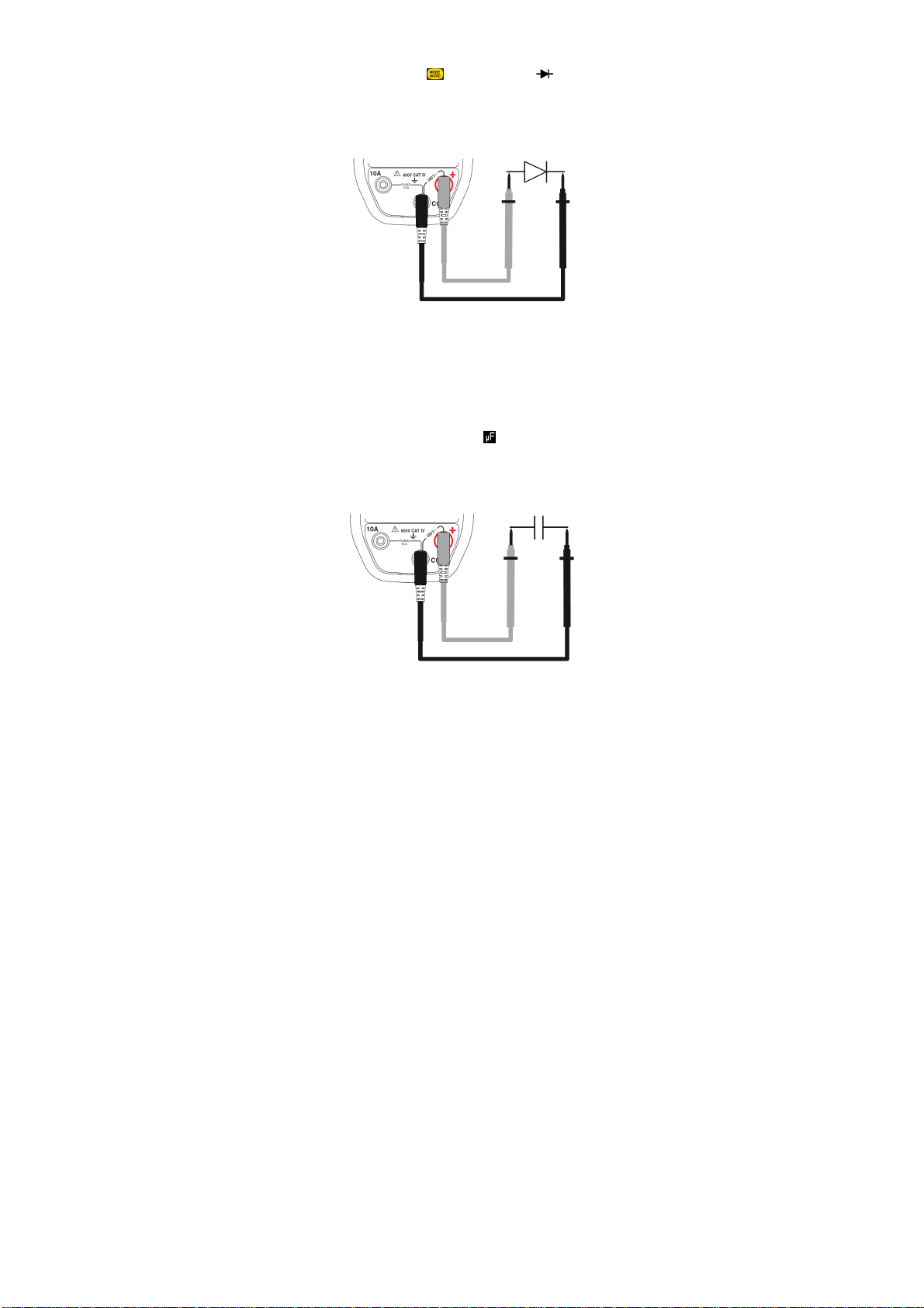
Italiano
2. Premete due volte
3. Allacciate il cordone nero al morsetto COM e il cordone
. Appare il simbolo
;
rosso a “+”;
4. Posizionate le punte di contatto sui morsetti del
componente;
Il valore della tensione sviluppata si visualizza allo schermo.
3.1.5 Misura di capacità
Attenzione : tutte le misure di capacità vanno effettuate fuori
tensione. Rispettare la polarità dell’allacciamento (+ al morsetto
rosso, - al morsetto nero)).
Per misurare la capacità, procedete come segue:
1. Accertatevi che la capacità da misurare sia scarica;
2.
Posizionate il commutatore su ;
3. Allacciate il cordone nero al morsetto COM e il cordone
rosso a “+”;
4.
Posizionate le punte di contatto sui morsetti del
componente
.
Il valore della capacità misurata si visualizza allo schermo.
98 - 138
Page 99

Italiano
3.1.6 Misura di temperatura
Per misurare la temperatura, procedete come segue:
1. Posizionate il commutatore su ;
2.
Premete
(°C o °F) ;
Osservazione : l’unità visualizzata per difetto è in °C.
3. Allacciate l’adattatore per sonda di temperatura (rif. 1) ai
morsetti COM e “+” rispettando la polarità;
4. Allacciate la sonda di temperatura (rif. 2) sull’adattatore
rispettando la polarità;
Nota: in caso di sonda non allacciata oppure interrotta, il
display indica OL
per selezionare l’unità della scala termica
Il valore della temperatura della termocoppia si visualizza allo
schermo.
3.1.7 Misura d’intensità
1. Posizionate il commutatore su ;
2. Selezionate AC o DC premedo . Per difetto,
l’apparecchio è in modo AC. In funzione della vostra
selezione, lo schermo visualizza AC o DC.
3. Allacciate il cordone nero sul morsetto COM e il cordone
rosso su “10°”;
4. Collegate il multimetro in serie nel circuito.
99 - 138
Page 100

Italiano
Il valore dell’intensità misurata si visualizza allo schermo.
3.1.8 Non Contact Voltage NCV
1. Posizionate il commutatore su ;
2. Avvicinate il C.A5233 (zona di rivelazione NCV) al o ai
conduttori potenzialmente sotto tensione (presenza di
fase);
3.
Se presenza di tensione rete di 230V (modello Europeo),
la retroilluminazione si accende in rosso; in caso
contrario, rimane spenta.
3.2 FUNZIONI DEI TASTI
Le funzioni dei tasti , , , , e sono
accessibili mediante pressioni successive brevi o lunghe. Un
segnale sonoro convalida ogni pressione.
3.2.1 Tasto
Questo tasto permette di selezionare la natura e il modo di
visualizzazione delle misure nonché disattivare l’arresto
automatico dell’apparecchio, all’avviamento, in combinazione
con il commutatore. Una pressione mantenuta in fase
d’avviamento ruotando il commutatore da verso qualsiasi
posizione disattiva l’arresto automatico .Il simbolo non è
visualizzato. Per difetto, l’arresto automatico è attivato, il
simbolo è visualizzato.
Osservazione : il modo DC è attivato per difetto.
100 - 138
 Loading...