

Page 1
User M anual
Page 2

Edition
Notes
The WELL Fit User Manual Re v. 3 includes a description, safety precautions, and installation,
as of the releas e date
Trademarks
CHAUVET, the Chauvet logo and WELL Fit are registered trademarks or trademarks of
. (d/b/a Chauvet and Chauvet Lighting) in the United States and other
countries. Other company and product names and logos referred to herein may be trademarks
of t hei r respect ive companies.
Copyri ght Not i c e
The works of authorship contained in this manual, including, but not limited to, all design, text
El ec tronical l y publi shed by Chauvet in t he United S tat es of Am eri ca.
Manual Use
Chauvet authoriz es i ts c ust omers t o download and pri nt t his m anual for profes sional informati on
sage, copy , st orage, dis tri bution, modific ation,
her purpose without written consent from
Chauvet.
Document
Printing
For bett er resul ts , print this docum ent in c olor, on l ett er siz e paper (8.5 x 11 in), double-sided. If
Intended
Any person in charge of i nstal ling, operat ing, and/ or maint aining t his product s hould c omplet ely
read through the guide that s hipped with the product, as well as this manual, before installing,
operating, or maintaining this product.
Disclaimer
Chauvet believes that the information contained in this manual is accurate in all respects.
However, Chauvet ass umes no responsibility and specifically disclaims any and all liability to
used by any errors or omissions in this
document, whether such errors or omissions result from negligence, accident or any other
cause. Chauvet reserves the right to revise the content of this document without any obligation
and does not com m i t to m ake, any s uch revisions..
Document
Revision
The WELL Fit User Manual Rev. 3 is the revised edition of this manual. Go to
Edit ion Not es
Audience
programming, operation, and maintenanc e instructions for the W ELL Fit
of t hi s editi on i n 2017.
Chauvet & Sons, LLC
and images are owned by Chauvet .
© Copyright 2017 Cha uve t & Sons, LLC. All rights reserved.
purposes only . Chauvet expressly prohibits the u
or printing of this manual or its content for any ot
usi ng A4 paper (210 x 297 mm ), c onfigure your pri nt er to s cal e t he content accordingly.
any party for any loss, damage or disruption ca
to notify any pers on or company of suc h revisi on, however, Chauvet has no obl igati on to mak e,
www.chauvetprofessional.com for t he l at est version.
WELL Fit User Manual Rev. 3
Page 3

Table of Content s
T able of Contents
1. Before You Begin ........................................................................................................................................... 1
W hat Is Inc l uded ...............................................................................................................................................1
Claims ................................................................................................................................................................................................................ 1
Manual Conventions ........................................................................................................................................................................................ 1
Symbols ............................................................................................................................................................................................................. 1
Safety Not es .....................................................................................................................................................2
Pers onal Safety ................................................................................................................................................................................................ 2
Mounting And Rigging ..................................................................................................................................................................................... 2
Power And Wiring............................................................................................................................................................................................. 2
Operation ........................................................................................................................................................................................................... 2
Expec ted LE D Lifespan .....................................................................................................................................2
2. Introduction..................................................................................................................................................... 3
Description .......................................................................................................................................................3
Features ...........................................................................................................................................................3
Well Fit Overview ..............................................................................................................................................4
Product Dim ensi ons ..........................................................................................................................................5
Charging C ase Dimens i ons (Not sol d with t he Single Fi xt ure) ..............................................................................6
3. Setup ................................................................................................................................................................ 7
AC P ower .........................................................................................................................................................7
AC Plug .............................................................................................................................................................................................................. 7
Bat tery Charge Note s ...................................................................................................................................................................................... 7
Repl ac ing t he Fuse .......................................................................................................................................................................................... 7
DM X Linki ng .....................................................................................................................................................7
DMX Personalities............................................................................................................................................................................................ 7
W i reless Operat i on ............................................................................................................................................8
Initial Set up........................................................................................................................................................................................................ 8
Configuration ..................................................................................................................................................................................................... 8
Product Pairing ................................................................................................................................................................................................. 8
St or age Note s ................................................................................................................................................................................................... 8
W-DMX Setup ................................................................................................................................................................................................... 8
IR In frar ed R emote Co nt rol ................................................................................................................................9
IR Rem ote Oper atio n ....................................................................................................................................................................................... 9
Mounting ........................................................................................................................................................ 10
Orientation .......................................................................................................................................................................................................10
Rigging .............................................................................................................................................................................................................10
Procedure ........................................................................................................................................................................................................10
4. Operation....................................................................................................................................................... 11
Control Panel Description ................................................................................................................................ 11
Control Opti ons ............................................................................................................................................... 11
Programming .................................................................................................................................................. 11
Control Panel Lock .......................................................................................................................................... 11
Passcode .........................................................................................................................................................................................................11
Menu Map ...................................................................................................................................................... 11
Menu Map ( Cont .) ........................................................................................................................................... 12
Configur at i on (S tandal one) .............................................................................................................................. 13
Automatic Programs ......................................................................................................................................................................................13
Fixed Stat ic Color ...........................................................................................................................................................................................13
Manual St atic Color........................................................................................................................................................................................13
Dimmer Profile s ..............................................................................................................................................................................................13
White Cali br ation ............................................................................................................................................................................................13
Backlight ..........................................................................................................................................................................................................14
Sof tware I nformation......................................................................................................................................................................................14
Fixture Hours ...................................................................................................................................................................................................14
WELL Fit User Manual Rev. 3 -i-
Page 4

Table of Content s
LED T est ..........................................................................................................................................................................................................14
Fac tory Reset..................................................................................................................................................................................................14
Configur at i on (DMX)........................................................................................................................................ 14
DMX Personalities..........................................................................................................................................................................................14
DMX Control....................................................................................................................................................................................................14
Wireless Settings............................................................................................................................................................................................14
IR Setting .........................................................................................................................................................................................................14
DM X V al ues.................................................................................................................................................... 15
DM X V al ues (Co nt. ) ........................................................................................................................................ 16
5. Technical Information .................................................................................................................................. 17
Product M ai nt enance....................................................................................................................................... 17
6. Technical Specifications ............................................................................................................................. 18
Returns .......................................................................................................................................................... 19
Contact Us ............................................................................................................... Error! Bookmark not defined.
-ii- WELL Fit User Manual Rev. 3
Page 5
What Is
Pack
Single
• 6–WE LL Fit
Quic k Reference G uide
• W E LL F i t
Quic k Reference Guide
Claims
Carefully unpack the product immediately and check the charging case to mak e sure all the
or the contents (the product and included acces sories) appear damaged
. F ailure
to report damage t o the c arrier imm ediatel y may invalidate y our clai m. In addit ion, keep t he box
nts or parts, damage not related to shipping, or
conceal ed dam age, fil e a clai m wi t h Chauvet wit hi n 7 days of deli very.
Manual
1–512
A range of values i n t he text
50/60
A set of mut ual l y exc l usi ve values in the t ext
<SET>
A but ton on t he product ’ s cont rol panel
Settings
A product func tion or a menu opti on
MENU>Settings
A sequenc e of menu options
1–10
A range of menu values from whi ch t o choos e in a menu
Yes/No
A set of two mutually ex clus ive menu opt ions in a menu
ON
A uni que value to be ent ered or sel ect ed i n a m enu
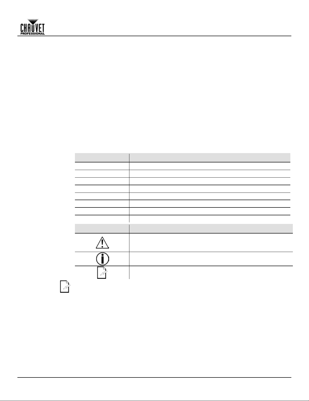
Symbols
Criti cal i nstall ation, configurat i on, or operat i on i nformation. Fail ure to
damage third-party equi pm ent , or cause harm to t he operator.
The te rm “DMX” used throughout this ma nual refers to the USITT DMX512-A di gi tal data
transmission protocol.
1. Before You Be gin
Included
Conventions
• Neutrik powerCON power c ord
• IR remote
• Charging case
• W arranty Card
•
parts are in the pack age and are in good condit ion.
If the charging case
from shipping or show signs of mishandling, notify the carrier immediately, not Chauvet
and cont ents for inspec ti on.
For other issues, such as missing compone
Convention Meaning
• IEC power cable
• IR remote
• Charging base
• W arranty Card
•
Before You Begin
Symbols Meaning
com pl y with t hi s information may cause t he product not t o work,
Important ins t al l ation or configurat i on i nformat i on. F ai l ure t o com pl y
with thi s i nformation may keep t he product from working.
Useful information.
WELL Fit User Manual Rev. 3 -1-
Page 6

Safet y Notes
Read all the following Safety Notes before working with this product. These notes include
import ant informat ion about the inst allat ion, us age, and mai ntenanc e of t hi s product .
This product contains no user-serviceable parts. Any reference to servicing in this User
housing or a ttem pt a ny repai rs.
Personal Safet y
• Avoid di rect eye ex posure t o the light sourc e while t he product is on.
Do not t ouch t hi s product ’ s housing duri ng operation becaus e it m ay be very hot.
Mounting And
• Do not submerge this product (IP65). Temporary outdoor operation is fine.
• W hen hangi ng thi s product , al way s sec ure to a fasteni ng device usi ng a safety cable.
Power And
• Al way s m ake s ure you are connec ti ng t hi s product to t he proper voltage in accordanc e with
• Never disconnect thi s product by pul l i ng or t uggi ng on the power c abl e.
Operation
• Do not operat e this product if you see damage on t he housi ng, lens es, or cabl es. Have t he
In cas e of a s eri ous operat i ng probl em , stop us i ng thi s product imm ediatel y!
In the unlikely event that your Chauvet product requires service, contact Chauvet
Technica l S upport.
Expected LED
LEDs gradually decline in brightness over time, primarily due to heat. Packaged in clusters,
conditions. For this
LEDs at their fullest intens ity s ignificantly reduces the LEDs’ lifespan.
projec t i on intensi t y m ay al s o hel p to ext end the LE Ds’ lifespan.
Before You Begin
Rigging
Manual wil l only a ppl y to properly trai ned Chauvet certifie d te chnicians. Do not open the
All a ppli ca bl e loca l code s and regul ations apply to proper install ation of this product.
• Al way s di s connect this product from i ts power source before servicing.
• Al way s connec t t hi s produc t t o a grounded ci rc ui t t o avoid the ri sk of el ect rocut i on.
• Do not operate the product in a seal ed enclos ure or in an area wit hout air circ ulat ion.
•
• CAUTION: W hen trans ferring product from ext reme tem perature envi ronments , (e. g. cold
truc k to warm hum i d bal l room ) condensat i on m ay form on the i nt ernal el ect roni cs of t he
product . To avoid c ausi ng a failure, allow product to full y ac cli mate to the s urrounding
env ironment befor e connecting it to power.
• Not for permanent outdoor i ns tal l at i on i n l ocat i ons with ext rem e environmental c ondi ti ons .
This incl udes, but i s not li m i ted t o:
• W here the normal hi gh or low tem peratures of the locat ion ex ceed t he tem perature
ranges i n this manual .
• Locations that are prone to flooding or being buried in snow.
• Other areas where t he product will be subj ec t t o extreme radi ation or caust i c
substances.
• Only use the ret ract abl e foot t o ti l t the produc t .
• Be sure retrac tabl e foot is cl osed c om pl etel y before insert i ng i nto t he chargi ng case.
• Mount this produc t in a locat ion with adequate ventilat ion, at l east 20 in (50 cm) from
adjac ent s urfaces.
• Mak e sure t here are no flammable m aterials cl ose to t his product while it is operat ing.
Wiring
Lifespan
-2- WELL Fit User Manual Rev. 3
the spec i ficat i ons i n this m anual or on the produc t’s s peci ficat ion label.
• To eliminat e unneces sary wear and improve i ts lifes pan, during periods of non-use
com pl etely di sc onnect the product from power via breaker or by unpluggi ng i t.
• DO NOT connect the charging cas e to a di m m er or rheos tat .
damaged parts replaced by an aut horized tec hnic ian at once.
• Do not cover the ventilat ion slot s when operating t o avoid int ernal overheati ng.
• The maximum ambient temperature is 113 °F (45 °C). Do not operat e this produc t at a
higher temperature.
•
LEDs exhibit higher operating temperatures than in ideal, single-LED
reason, using clustered
Under norm al condit ions , this lifespan c an be 40,000 t o 50,000 hours . If ext ending thi s li fespan
is vital, lower the operating temperature by improving the ventilation around the product and
reducing the ambient temperature to an opti mal operat ing range. In addit ion, l imit ing the overall
Page 7

Description
The WELL Fit is a quic k setup, high-powered LED up-lighter. This s mall battery powered accent
wash l ight c omes in a reflect ive c hrome housi ng designed t o blend int o any déc or. W ELL Fi t c an
lternatively, it can be
cont rolled manual ly from t he OLED di splay on t he product.
Features
• 3-, 4-, 6- or 10-channel quad-col or LED was h product
your i nves tm ent.
2. Introduction
be controlled wireles sly either by W -DMX or by the included IR remote. A
• Operating modes:
• 3-channel: HS I control
• 3-channel: HSV cont rol
• 4-channel: RGBW
• 6-channel: RGBW, di m m er, strobe
• 10-channel: RGBW , dimmer, st robe, col or mac ro/whit e bal ance, auto programs ,
• A compl etely wi reless IP 65 rated bat tery powered up-light with four high powered quad
col ored RGB A LE Ds t hat is cont rol l ed by W-DMX or IR remote.
• Chrome exterior for blending into its surroundings.
• Drop i n case c hargi ng for easy st orage and re-charging of t he batt ery. (Not available wit h
Si ngle Fix ture)
• 8 hours of operat i on at full and a qui ck 5 hours charging ti m e for frequent use.
• Bui lt i n aut om ated programs recall abl e by IR, W DMX or manual l y.
• Bui lt i n kicks tand for pos i tioni ng light where you need it.
• M12 t hreaded i nsert for easy cl am p i ns tal l at i on and a Kensington l ock posi t i on for securing
dimm er speed, auto s peed
Introduction
WELL Fit User Manual Rev. 3 -3-
Page 8
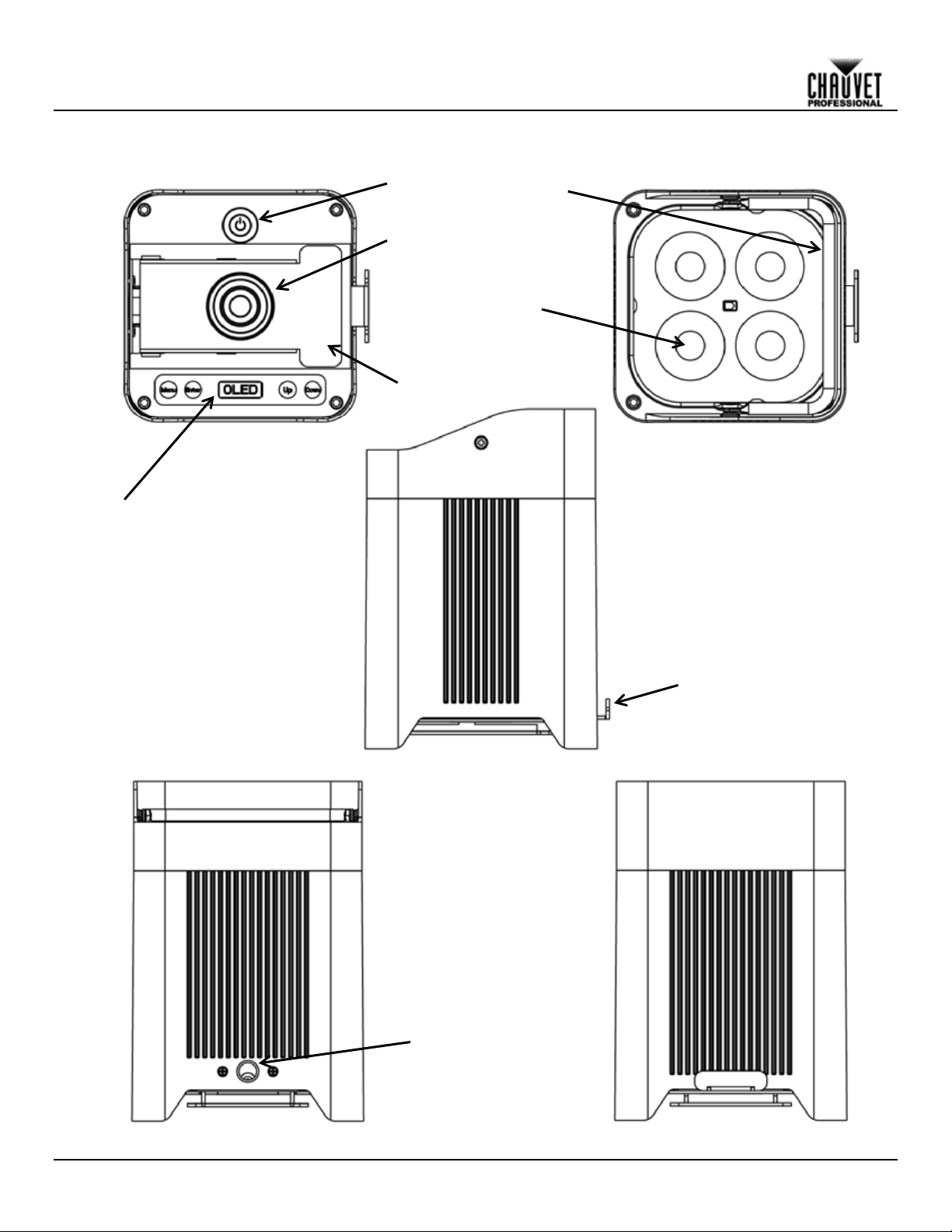
Bottom View
Top View
Side View
Front Vi ew
Rear View
Introduction
Well Fit Overview
Control Panel
Power Switc h
Charging Socket
Retractable Foot
M12
Threaded
Mounting
Hole
Handle
Quad Color LED
R etr act ab l e F o o t Release
-4- WELL Fit User Manual Rev. 3
Page 9

7.95 in
202 mm
5.71 in
145 mm
7.01 in
178 mm
5.43 in
138 mm
5.43 in
138 mm
Introduction
Product Dimensions
WELL Fit User Manual Rev. 3 -5-
Page 10

15.87 i n
403 mm
16.54 i n
420 mm
16.77 i n
426 mm
21.26 i n
540 mm
9.72 i n
247 mm
12.13 i n
308 mm
18.50 i n
470 mm
17.83 i n
453 mm
12.13 i n
308 mm
21.14 i n
537 mm
20.43 i n
519 mm
Introduction
Charging Case Dimens ions (N ot sold with the Single Fixture)
-6- WELL Fit User Manual Rev. 3
Page 11

AC Power
Each WELL Fit has an auto-ranging battery charger inside the flight case that works with an
input voltage range of 100 to 240 VAC, 50/60 Hz. To determine the power requirements for the
The listed current rating indicates the maximum current
from the Chauvet website: www.chauvetprofessional.com.
• Alwa ys connect this product to a prote cted circuit with a n a ppropriate el ectrical
completely disconnect the product from power via breaker or by unplugging it.
Never conne ct this product to a rheostat (varia ble re sistor) or dimme r circuit, e ven if the
rheostat or di mm er cha nne l serves only a s a 0 to 100% switch.
AC P lug
The WELL Fit charging case comes with a power input cord terminated with a Neutrik
A connector on one end and an Edis on plug on the other end (U.S. market). If the
that c ame wit h your produc t has no plug, or i f you need to c hange the E dis on
plug, use the tabl e below to wire the new plug.
AC Live
Black
Brown
Yel low or Brass
AC Neutral
White
Blue
Silver
AC Ground
Green/Yellow
Green/Yellow
Green
Battery Charge
• Recharge t he batt ery within three days from l ast use.
• Perform a full di sc harge/recharge c yc le every three m onths .
Replacing the
Fuse
The WELL F it has no ext ernal fuse. However, the c harging c ase and/ or the c harging bas e come
4. Sc rew the fus e hol der cap back i n pl ace and reconnec t power.
DMX Linking
The WELL Fit will work with a DMX controller using a wireless DMX c onnect ion. If usi ng other
compatible products with the WELL Fit, you can control each individually with a single
DMX controller.
DMX
The W ELL Fit uses a wireless DMX data c onnection for the 4 Ch, 6 Ch, 10Ch, HSI and HSV
personalities.
If you are not famil i a r wi th or need m ore i nforma tion about DMX standa rds, Master/ Sl ave
connectivity, or the DMX cables needed to link this product to a DMX controller,
downl oad the DMX P rim er from the Chauvet website: www.chauvetprofessional.com.
3. Setup
Setup
WELL Fit, refer to the label affixed to the product. You can also refer to the Technical
Specifications chart in this manual.
draw during normal operation. For more information, you may download Sizing Circuit Breakers
ground to a void the risk of electrocution or fire .
• To eliminate unneces sary wear and improve its lifes pan, during periods of non-use
powerCON
power input cord
Connection Wire (U.S.) Wi re (Europe) Screw Color
Notes
Personalities
• Recharge t he batt ery t o full capacity before st ori ng this product.
• For best resul t s, charge the batt ery i n a t em perature bet ween 32 º F (0 º C) and
95 ºF (35 ºC).
• W hen charging the batt ery, keep t he product at no l ess than 1 m from any open flam e or
hot pl at e.
• W hen charging t he batt ery inside t he road c ase charger, keep t he road c ase’s c over open.
• Al ways charge t he batt ery wit h the product i n an upright posit ion.
• Do not charge t he batt ery for more t han 24 hours.
with a replac eabl e fus e.
1. Disc onnect this produc t from power.
2. Using a flat -head s crewdriver, uns crew the fuse holder c ap from the housing.
3. Remove blown fuse and repl ace wit h a good fuse of the same t ype and rati ng.
DMX-
DMX personalities.
• Refer t o the Introduction chapt er for a bri ef des cript ion of each DMX pers onality .
• Refer t o the Operation chapt er to learn how to configure t he WE LL F i t to work i n t hese
personalities.
• The DMX Values s ect i on provides you wit h detai l ed i nformat i on regarding the DM X
WELL Fit User Manual Rev. 3 -7-
Page 12

Wireless
Operation
In optimal conditions, the WELL Fit can operate up to 300 m (900 ft) away from the W -DMX
DMX transmitter
for wireles s operat ion.
Once a WDMX receiver has been linked to a specific WDMX transmitter, it will remain
linke d to that spe cific tra nsmitter until i t is linke d to a di ffere nt one .
Initia l Se tup
1. Turn t he W-DMX t rans m i tt er on.
5. Turn the W E LL F i t on.
Configuration
1. From the WELL Fi t’s c ontrol panel, go t o DMX Add re ss.
W E LL F i t will show a ϟ in front of the bars for 3 seconds while a connec tion i s est ablis hed.)
Product Pai r ing
If the WELL Fit has already been paired with the W-DMX transmitter, the Signal Strength
of the s ignal. In this c as e, the
st rength of the signal .
Storage Notes
• Always s tore the product in an upright pos ition (≤ 10° tilt).
• Store charged product (s) in a dry environment, away from direct sunli ght.
W-DMX operation can be interrupted or inhibited by liquid masses between the
transmitter and receiver such as water, snow, or people. For best results, keep the area
between the transmitter and receiver clear of any liquid mass.
Contr ol Panel
W-DMX Transmitter
Setup
transmitter. The W-DMX receiver in the WELL Fit must be paired with the W-
2. Connect t he W -DMX transmi tt er to a DMX c ontroll er.
3. Plac e the WE LL F i t within 300 m from the W-DMX transmitter.
4. Disc onnect any DMX c able from t he WE LL Fit .
2. Selec t t he st art addres s, as wit h any other DMX compat ible produc t.
3. Go to Wireless Set t i n g > R eceive.
4. Select On. (The S ignal St rength Indic ator will show a ? in front of the bars )
5. Press t he reset butt on on t he W-DMX transm itt er. (The S ignal S trengt h Indicator on the
Indicator in the middle of the LCD screen will show the strength
W E LL F i t is ready to work i n Wi rel ess m ode.
Pai ring the WE LL Fit and a new W-DMX transmitter:
1. From the WELL Fi t’s c ontrol panel, go t o Wirele ss Setting.
2. Select Reset. The Si gnal St rength Indic ator on the WELL F i t will show a ? in front of the
bars.
3. From the W-DMX trans m i tt er, press < RESET> (t he Signal Indicat or on t he trans mit ter wil l
flash).
4. Once t he trans m i tt er has found t he WE LL F i t, the S i gnal i ndi c ator on the W-DMX
transmitter will illuminate solid.
5. The Signal Strengt h Indicator i n the middle of the LCD screen on t he WE LL F i t will show t he
• Recharge t he batt ery t o full capacity before st ori ng the produc t .
W-DMX Setup
-8- WELL Fit User Manual Rev. 3
Page 13

IR Infrared
Remote
Infrared (IR) mode allows the product to be controlled with an infrared remote
remot ely s et t he product to various modes ; adjus t
uvet. To
2. Select On to act i vate t he IR Rec ei ver.
It ma y be nece ssary to turn the product off and on aga in w hen sw itching
I R Remot e
Operation
Be sure the IR remote is point ing direc tly at t he product and there is nothing i n
Automatic Mode
2. Press <+> or <–> to increas e or decreas e the out put level.
Note: The I R re mo te w ill not re spond to a ny inputs w hen the Bla ck Out mode is a ctiva ted. If the
remote does not respond when a button is pressed, try pressing <BLACK OUT>. You may have
inadvertently activated the Black Out mode.
Control
controller. The IR remote can
the color, speed and sens i tivity ; and set the s trobe.
The WELL Fit is compatible with the included IR remote from Cha
enable use wit h the IR remot e, foll ow the ins truc tions below:
1. Go to I R S ettin g in t he m ain level.
from W-DM X to IRC and v ise-versa.
between the remote and the produc t.
Aut om atic m ode wi l l enabl e you t o run the aut om atic program s on the produc t.
To turn on Aut omati c mode:
1. Press <AUTO> on the IR remot e.
2. Press <+> or <–> t o choose between t he four different aut o program s.
To adjust the speed of the automati c program:
1. Press <SPEED> on t he IR remote.
2. Press <+> or <–> to either inc rease or dec rease t he speed of the program.
Manual Color Control
To choose a spec ific col or with t he IR remote:
3. Press <MANUAL> on the IR remote.
4. Press any num ber bet ween <0> and <9> t o choos e your c olor.
To manually cont rol the RGBA perc entage:
1. Press <MANUAL> on the IR remote.
2. Press <R>, <G>, <B>, or <A> (red, green, bl ue, or am ber) t o choose y our
color.
3. Press <+> or <–> to increas e or decreas e the perc entage of each color.
Miscel lane ous Opera tion
To adjust the strobe rat e of the program:
1. Press <STROBE> on t he IR remote.
2. Press <+> or <–> to increas e or decreas e the s trobe rat e.
3. Press <STROBE> again t o turn off the strobe.
To c hoose a fade aut o program:
• Press <FADE> repeatedl y on the IR remote to c hoose between t he two
auto program fade options
To black out t he lights :
• Press <BLACK OUT> on t he IR rem ote. This will turn off all the l i ght s unt i l
the button is pressed again.
To adjust the output level:
1. Press <%> on the IR remot e.
Setup
WELL Fit User Manual Rev. 3 -9-
Page 14

Mounting
Before mounting this product, read and follow the Safety Notes. For our CHAUVET
Professional line of mounting cl am ps, go to http://trusst.com/products/.
Orientation
Always mount this product in a safe position and make sure there is adequate room for
Rigging
Chauvet recommends using the following general guidelines when mounting this product.
• W hen selec ti ng an ins tall ation l ocat ion, c onsi der easy acc ess t o t his product for operati on,
our CHAUVET Profess ional li ne of s afet y c abl es, go to http://trusst.com/products/.
Procedure
The WELL Fit comes with an M12 threaded mounting hole to which you c an attach mounting
When mounting the product overhead, always use a mounting clamp and
safety cable. Mount the product securely to a rigging point, such as a pipe or truss. When
lamp of appropriat e weight c apaci ty . You m ust
For our
When mounting the product on the floor, make sure that the product and any cables are away
from people and vehic les.
Floor M ount ing
Ove r head M ounting
Setup
ventilation, configurati on, and m aintenanc e.
programmi ng adjus tm ents, and routi ne maintenance.
• The product is not intended for permanent installation.
• Mak e sure t o mount this produc t away from any flamm able materi al as indic ated in the
Safety Notes
• If hanging thi s product , m ake s ure that the m ount i ng l ocation can support the produc t ’ s
weight. S ee the Techni cal S peci ficat ions
product.
• W hen hanging this produc t, al ways secure t o a fas tening devic e usi ng a safety cable. F or
clamps for hanging.
rigging the produc t, you s hould use a m ounting c
supply your own mounting clamps. Use at least one mounting point per product.
CHAUVE T Profes sional li ne of mounting c lam ps, go to http://trusst.com/products/.
.
for the wei ght-bearing requirem ents of this
Handle
Mounting Diagra m
M12 Threade d
Mounting Hole
-10- WELL Fit User Manual Rev. 3
Page 15

Control Panel
<ON/OFF>
Turns product on/ off
<MENU>
Exits from the c urrent menu or func t i on
<ENTER>
Enabl es the current ly di splay ed menu or s ets the current ly s elec ted
value in to t he current func tion
<UP>
Navigates upward through t he menu lis t or inc reases the numeric
value when in a func tion
<DOWN>
Navigates downward t hrough the menu l ist or decreases the numeri c
value when in a func tion
Control
Options
DMX range. This enables c ontrol of up to 51
Programming
Refer to the Menu Map to understand the menu options. The menu map s hows the main level
• Press <MENU> repeat edl y to ex i t t o the previous m ai n l evel.
This setting enables you to activate or disable the control panel lock, which keeps non-
2. Select On or Off.
After bei ng prompted to enter t he pass code:
• Press <UP>, <DOWN>, <UP>, <DOWN>, <ENTER>.
Main Level
Program m i ng Level s
Description
Auto Show
Auto 1–5
Speed
0–100
Aut om atic program s and speed
R
Red
G
Green
B
Blue
A
Amber
GB
Green/Blue
RB
Red/Blue
RG
Red/Green
RGB
Red/Green/Blue
RA
Red/Amber
GA
Green/Amber
BA
Blue/Amber
RGA
Red/Green/Amber
RBA
Red/Blue/Amber
GBA
Green/Blue/Amber
RGBA
Red/Green/Blue/Amber
R
G B A
4. Operation
Description
Set the W ELL Fit starting addres s in the 001–512
product s i n the 10-channel 10Ch personality.
and a variabl e num ber of programming levels for each option.
• To go to the desi red main level, press <MENU> repeatedly until the opt i on shows on the
• To selec t an opt ion or value withi n the c urrent programm ing level, press <UP> or <DOWN>
Operation
Button Function
dis pl ay. Pres s <ENTER> to s el ect. This wil l t ake you t o the firs t programm i ng l evel for that
option.
unti l t he option shows on the displ ay. P ress <ENTER> to s el ect. In thi s cas e, if t here i s
another programm i ng l evel, you wil l see t hat firs t opt i on, or y ou wi l l see the select ed value.
Control Panel
Lock
authoriz ed personnel from changing the product’s settings.
1. Go to the Ke y L o ck mai n level.
Passcode
Menu Map
Fix ed Color
Static
Manual
Color
Value 0–255
Combines red, green, blue, and amber to
mak e a cust om color (0–100%)
WELL Fit User Manual Rev. 3 -11-
Page 16

Off
No dimm er
Dimm ing curves Dimmer 1 (fast ) to Dimmer 3
(slow)
Turns off dis play bac k light after 10 sec of
inactivity
Turns off dis play bac k light after 20 sec of
inactivity
Turns off dis play bac k light after 30 sec of
inactivity
On
Dis pl ay backli ght al way s on
Test
Turns on all LEDs i n sequence for t es ti ng
Fix ture Hours
Shows tot al produc t hours
Ve rsion
Shows i nstall ed software version
Sel ects DM X address (highest channel
restricted to personality chosen)
4 Ch
4-channel: RGB A c ontrol
6 Ch
6-channel: RGB A c ontrol, dim mer, and s trobe
10-channel: RGBA c ontrol , dimmer, s trobe,
auto speed, di m m er speed
HSV
3-channel: HSV cont rol
HSI
3-channel: HS I control
Master
Slave
R
Set s red LED max imum value
G
Sets green LED maximum value
B
Set s blue LED m axim um value
Off
Turns wireless DMX functi on off
On
Off
On
Off
On
Off
On
Off
Operation
Menu Map (Cont.)
Main Level Program m i ng Level s Description
Dimmer Mode
Back Light
Information
DMX Address 001–512
DMX Channel
Dimmer 1–3
10S
20S
30S
10Ch
col or macro/ white bal ance, auto programs,
Master/Slave Mode
White Balance Balance
Wireless Setting Receive
IR Setting
Key L o ck
Factory Reset
Value 125–255
On Reset
Reserved for future use
Reset s t he wi rel ess sett i ng
Ac tivates /deac tivates IR rec eiver
Turns the passc ode on or off
Reset s t o fac tory defaults
-12- WELL Fit User Manual Rev. 3
Page 17

Configuration
Use st andal one configurat i on to operat e the product wi t hout a DM X cont rol l er.
Automatic
Aut omati c programs allow for dynam ic RGBA col or m i xing wi thout a DM X c ontroll er.
4. Selec t t he desi red speed 0–100.
Fixed Static
The fix ed stat i c c ol or m ode al l ows for pres et RGB W col or m i xing wi t hout a DM X cont rol l er.
3. Selec t the des ired col or combi nation. See M enu Map.
Manual Static
The manual static color mode allows for manually customizable RGBA color mixing without a
6. Repeat for the other c olors .
Dimmer P ro files
This setting determines how fast the output of the WELL Fit changes when you modify the
This setting provides three different
2. Selec t a di m m er profile (Off, Dimmer 1, Dimmer 2, or Dimmer 3).
OFF:
The out put i s proport i onal (l i near) t o the dimm er and RGBW channel values.
Dimmer 1–3:
The out put follows the dimmer and RGBW c hannel values bas ed on the
slowest.
Wh ite Ca lib r at io n
This setting allows you to select the white color shown by the WELL Fit when the DMX
6. Repeat for the other c olors .
When selecting White Balance, you will only be able to define the values of red (R),
green (G), and bl u e (B).
The va lues of re d (R), gree n (G), a nd blue (B) configured from W hi te Bal ance wi ll define
the color temperature shown when the RGB faders are set to 255.
(Standalone)
Programs
Color
Color
1. Go to the Auto Show main l evel.
2. Selec t t he desi red aut om ati c (Auto 1–5) program.
3. Go to the Speed programming level.
You cannot e dit a ny of the a utomatic program s (Auto 1–5).
1. Go to the Static m ai n l evel.
2. Selec t t he Fixed Color programming level.
DMX controller.
1. Go to the Static m ai n l evel.
2. Selec t t he Manual Color programming level.
3. Selec t t he desi red color R, G, B or A.
4. Go to the Value programming option.
5. Selec t t he desi red color value 0–255 (0–100%).
Operation
values of the red, green, blue, white, and dimmer faders.
opti ons t o si mulat e the dimmi ng curve of an incandes cent lighti ng product .
1. Go to the Dimmer Mode main l evel.
cont roller’s red, green, and blue faders are set to 255.
1. Go to the White Balan ce m ai n l evel.
2. Go to Balance.
3. Selec t a color (R, G, or B).
4. Go to Value.
5. Selec t a color value (125–255).
corres ponding di mmer c urve, Dimmer 1 being t he fastes t and D immer 3 the
WELL Fit User Manual Rev. 3 -13-
Page 18

Backlight
This setting allows you to set the amount of time the backlight on the
2. Select On (remains on), 10S (10 sec onds), 20S (20 s econds), or 30S (seconds).
Software
This opt ion shows what version of s oftware t he W ELL Fi t i s running.
2. Select Version and the version number will s how on t he dis play.
Fixture Hours
This opt ion shows the t otal amount of hours the WE LL F it has been turned on.
2. Select Fixture Hours and the tot al number of hours wil l s how on the dis play .
LED Test
This opt i on runs a chec k of t he LE Ds on the W E LL Fit by t urni ng on al l the LE Ds in s equence.
2. Select Te st programming level.
Factory Reset
This opt i on runs a chec k of t he LE Ds on the W E LL Fit by t urni ng on al l the LE Ds in sequence.
2. Select On to reset the produc t to fac tory set ti ngs.
Configuration
(DMX)
Use DMX configurat i ons to operate the product wi th a DMX c ontroll er.
DMX
This s ett i ng al l ows you to c hoose a partic ular DMX personali ty .
2. Selec t t he desi red pers onal i ty (4 Ch, 6 Ch, 10Ch, HSI, or HSV).
• See th e DMX Values section for the highest sta rting addre ss you ca n sele ct for e ach
the ne w personal i ty setting.
DMX Contr ol
In this mode, each produc t will respond t o a unique st arting addres s from t he DMX control ler. All
b. Selec t t he start ing address (001–512).
The hi ghest re com m e nded sta rting a ddre ss for each DMX mode i s as follows:
4 Ch
509
6 Ch
507
10Ch
503
HSI
510
HSV
510
Wireless Settings
This mode al lows y ou to c ontrol DM X wi reless ly . For det ailed s etup of thi s feature, see Wireless
2. Select Off.
Once a WDMX receiver has been linked to a specific WDMX transmitter, it will remain
linke d to that spe cific tra nsmitter until i t is linke d to a di ffere nt one .
IR Setting
This mode allows you to control the WELL Fit with an IR remote. For detailed setup of this
2. Select Off.
Operation
Information
W E LL F i t ’ s di splay st ays on after t he l ast butt on i s press ed on the cont rol panel .
1. Go to the BackLite main l evel.
1. Go to the Information m ai n l evel.
1. Go to the Information m ai n l evel.
1. Go to the Information m ai n l evel.
1. Go to the Factory Reset m ai n l evel.
Personalities
1. Go to the DMX Channel main l evel .
personality.
• Make sure that the sta rting addre sses on the va ri ous products do not overl a p due to
product s wit h t he same st art i ng address wil l respond i n uni son.
1. Selec t a DMX pers onal i ty as shown i n DMX Personalities.
2. Set the s tart i ng address :
a. Go to DM X Ad dre ss m ain l evel.
DMX Pe rsona l i ty DMX Address
Operation. To disabl e this feature:
1. Go to Wireless Set t i n g > R eceive.
feature, see IR Infrared Remot e Control. To dis able thi s feature:
1. Go to IR Setting .
-14- WELL Fit User Manual Rev. 3
Page 19

10Ch
1
Dimmer
000 ó 255
0–100%
2
Red
000 ó 255
0–100%
3
Green
000 ó 255
0–100%
4
Blue
000 ó 255
0–100%
5
Amber
000 ó 255
0–100%
000 ó 010
011 ó 255
No functi on
Slow to fast
000 ó 010
251 ó 255
No functi on
W hi t e 11
000 ó 051
255
No functi on
Aut o 5
9
Auto Speed
000 ó 255
Slow to fast
000 ó 051
204 ó 255
Pres et di m m er s peed from display m enu
Nonlinear dim ming curve 3 (s l owes t)
Operation
DMX Values
Channel Function Value Percent/Setting
6 Strobe
011 ó 030
031 ó 050
051 ó 070
071 ó 090
091 ó 110
111 ó 130
Color Macro + White
7
Balance
131 ó 150
151 ó 170
171 ó 200
201 ó 205
206 ó 210
211 ó 215
216 ó 220
221 ó 225
226 ó 230
231 ó 235
236 ó 240
241 ó 245
246 ó 250
R: 100% G: 0–100% B: 0
R: 100% –0 G: 100% B: 0
R: 0 G: 100% B: 0–100%
R: 0 G: 100% –0 B: 100%
R: 0 –100% G: 0 B: 100%
R: 100% G: 0 B: 100%–0
R: 100% G: 0–100% B: 0–100%
R: 100% –0 G: 100% –0 B: 100%
R: 100% G: 100% B: 100% A: 100%
W hi t e 1
W hi t e 2
W hi t e 3
W hi t e 4
W hi t e 5
W hi t e 6
W hi t e 7
W hi t e 8
W hi t e 9
W hi t e 10
8 Auto Programs
10 D i mm er S p eed
WELL Fit User Manual Rev. 3 -15-
052 ó 101
102 ó 152
153 ó 203
204 ó 254
052 ó 101
102 ó 152
153 ó 203
Aut o 1
Aut o 2
Aut o 3
Aut o 4
Linear dimmer
Nonlinear dim ming curve 1 (fastes t)
Nonlinear di mming c urve 2
Page 20

6 Ch
1
Dimmer
000 ó 255
0–100%
2
Red
000 ó 255
0–100%
3
Green
000 ó 255
0–100%
4
Blue
000 ó 255
0–100%
5
Amber
000 ó 255
0–100%
000 ó 010
011 ó 255
No functi on
Slow to fast
4 Ch
Channel
Function
Value
Percent/Setting
1
Red
000 ó 255
0–100%
2
Green
000 ó 255
0–100%
3
Blue
000 ó 255
0–100%
4
Amber
000 ó 255
0–100%
HSV
1
Hue
000 ó 255
0–100%
2
Saturation
000 ó 255
0–100%
3
Value
000 ó 255
0–100%
HSI
1
Hue
000 ó 255
0–100%
2
Saturation
000 ó 255
0–100%
3
Intensity
000 ó 255
0–100%
Operation
DMX Values (Cont.)
Channel Function Value Percent/Setting
6 Strobe
Channel Function Value Percent/Setting
Channel Function Value Percent/Setting
-16- WELL Fit User Manual Rev. 3
Page 21

Product
To mai ntain opti mum performance and mini miz e wear, c lean this product frequently . Us age and
up reduces light output
performance and can cause overheating. This can lead to reduced light source life and
7. Gently poli sh t he lens surfac es unt il they are free of haze and lint .
5. Techn ical Inf ormat ion
Maintenance
environment are contributing factors in determining the cleaning frequency.
As a rule, clean this product at least twice a month. Dust build-
inc reased mec hanical wear.
To clean y our product:
1. Unplug the product from power.
2. Wait until the product is at room temperature.
3. Use a vacuum (or dry c ompres sed ai r) and a soft brush t o rem ove dust col l ect ed on the
ext ernal vent s.
4. Clean all ext ernal surfaces wi t h a m i l d sol ution of non-amm oni a gl ass cl eaner or i sopropy l
alcohol.
5. Apply the s ol ution direc tly t o a soft , l i nt-free cot ton cloth or a lens cleani ng ti ss ue.
6. Wi pe any di rt or grim e to t he outs i de edges of t he l ens surface.
Always dry the external surfaces thoroughly a nd ca re full y a fter cle ani ng them .
Technical Inf ormat ion
WELL Fit User Manual Rev. 3 -17-
Page 22

Dimensions and
Length
Width
Height
Weight
5.4 in (138 mm)
5.7 in (145 mm)
7.95 in (202 mm)
7.4 lb (6.5 k g)
Note: Dimens ions in inc hes rounded t o the nearest dec imal digit .
Power
Pow er Suppl y Type
Range
Voltage Selection
Swit chi ng (internal)
100–240 VA C, 50/60 Hz
Auto-ranging
Consumption
(Single Product)
48 W
48 W
Consumption
(Charging Case)
288 W
288 W
Operating(Single Product)
0..44 A
0.23 A
Operating (Charging Case)
2.44 A
1.38 A
Fus e (Charging Cas e)
3.15 A, 250 V
3.15 A, 250 V
Fus e (Charging base)
1 A, 250 V
1 A, 250 V
Power input connec tor
(Charging Case)
Neutrik powerCON A
Neutrik powerCON A
Power input connec tor
(Charging Base)
IEC power cable
IEC power cable
Power c ord pl ug
Edi s on (U. S. )
Local plug
Light Source
LED
10W
50,000 hours
Quad-color RGBA
4
720 mA
Photometrics
Illumi nance @ 5 m
800 lux
Beam angle
11°
Fiel d angle
18°
Thermal
Max. External Temperature
Cooling System
113 °F (45 °C)
Convection
DMX
I/O Connectors
Connector Type
Channe l Ra nge
W i reless DMX
Wireless
3, 4, 6, or 10
Ordering
Product Na me
Item Code
UPC Nu mb er
W E LL F i t
03031152
781462215002
W E LL F i t (Singl e)
03031255
781462216030
Technical Specif icati ons
6. Tech nical Specif icatio ns
Weight
Parameter 120 VAC, 60 Hz 230 VAC, 50 Hz
Power I/O U.S./Canada Worldwide
Type Power Lifespan
Color Quantity Current
Parameter Standa rd Optics
-18- WELL Fit User Manual Rev. 3
Page 23

Returns
Send the product prepaid, in the original box, and with the original packing and accessories.
and request a Return Merchandise Authorization (RMA) number before shipping
del number, serial number, and a bri ef descri ption of
will refuse any product returned
without an RMA number.
DO NOT write the RMA number dire ctly on the box . Instead, wri te it on a properly a ffixed
label.
Once y ou have received the RMA number, inc lude t he following informat ion on a piec e of paper
properly. Any shipping damage resulting from inadequate
recommended.
Chauvet reserves the right to use its own discretion to repair or replace returned
product(s).
Technical Specifications
Chauvet will not issue c al l tags .
Call Chauvet
the product. Be prepared to provide the mo
the caus e(s) for the ret urn.
Clearly label the package with an RMA number. Chauvet
ins i de the box :
• Your name
• Your addres s
• Your phone number
• The RMA num ber
• A brief desc ription of t he problem(s)
Be sure to pack the product
packaging will be the customer’s responsibility. FedEx packing or double-boxing is
WELL Fit User Manual Rev. 3 -19-
Page 24

Contact
USA W ORL D HEADQUART ERS
General Information – Chauvet
Technical Support
EUROPE
General Information - Chauvet Europe BVBA
Technical Support
General Information - Chauvet Europe Ltd.
Technical Support
MEXICO
General Information - Chauvet Mexico
Voice: +52 (728) 690-2010
Technical Support
Outside the U.S., United Kingdom, Ireland, Mexico, or Benelux contact the dealer of record.
Follow their instructions to request support or to return a product. Visit our website for contact
details.
User Manual
Us
Address: 5200 NW 108th A venue
Sunrise, FL 33351
Voice: (954) 577-4455
Fax: (954) 929-5560
Toll free: (800) 762-1084
Voice: (844) 393-7575
Fax: (954) 756-8015
Email: chauvetcs@chauvetlighting.com
World Wide Web www.chauvetlighting.com
Address: S t okst raat 18
9770 Kruishout em
Belgium
Voice: +32 9 388 93 97
Address: Unit 1C
Brookhil l Road Industri al Es tate
Pinxton, Not ti ngham , UK
NG16 6NT
Voice: +44 (0)1773 511115
Fax: +44 (0)1773 511110
Address: A v. de las Part idas 34, 3-B
(Entrance by Calle 2)
Zona Industrial Lerma
Lerma, E do. de M éxico, CP 52000
Email: Eutech@chauvetlighting.eu
World Wide Web www.chauvetlighting.eu
Email: uktech@chauvetlighting.com
World Wide Web www.chauvetlighting.co.uk
Email: servicio@chauvet.com.mx
World Wide Web www.chauvet.com.mx
WELL Fit User Manual Rev. 3
 Loading...