

Page 1
User Manual
Page 2

EDITION NOTES
The VIP Drive 43s User Manual includes a description, safety precautions, installation, programming,
operation, and maintenance instructions for the VIP Drive 43s as of the release date of this edition.
Trademarks
CHAUVET, the Chauvet logo and VIP Drive 43s are registered trademarks or trademarks of Chauvet &
Sons, LLC (d/b/a Chauvet and Chauvet Lighting) in the United States and other countries. Othe r company
and product names and logos referred to herein may be trademarks of their respective companies.
Copyright Notice
The works of authorship contained in this manual, including, but not limited to, all design, text and images
are owned by Chauvet.
© Copyright 2016 Chauvet & Sons, LLC. All rights reserved.
Electronically published by Chauvet in the United States of America.
Manual Use
Chauvet authorizes its customers to download and print this manual for profession al information pu rposes
only. Chauvet expressly prohibits the usage, copy, storage, distribution, modification, or printing of this
manual or its content for any other purpose without written consent from Chauvet.
Document Printing
For best results, print this document in color, on letter size paper (8.5 x 11 in), double-sided. If using A4
paper (210 x 297 mm), configure the printer to scale the content accordingly.
Intended Audience
Any person installing, operating, and/or maintaining this product should comple tely read thro ugh the guide
that shipped with the product, as well as this manual, before installing, operating, or maintaining this
product.
Disclaimer
Chauvet believes that the information contained in this manual is accurate in all respects. However,
Chauvet assumes no responsibility and specifically disclaims any and all liability to any party for any loss,
damage or disruption caused by any errors or omissions in this document, whether such errors or
omissions result from negligence, accident or any other cause. Chauvet reserves the right to revise the
content of this document without any obligation to notify any person or company of such revision, howe ver ,
Chauvet has no obligation to make, and does not co mmit to make, any such revisions. Download the latest
version from www.chauvetprofessional.com
.
Document Revision
This VIP Drive 43s User Manual is the 1st edition of this document. Go to www.chauvetprofessional.com
for the latest version.
VIP Drive 43s User Manual Rev. 1
Page 3

TABLE OF CONTENTS
1. Before You Begin....................................................................... 1
What Is Included ........................................................................................... 1
Claims........................................................................................................... 1
Manual Conventions ..................................................................................... 1
Symbols ........................................................................................................ 1
Safety Notes.................................................................................................. 2
2. Introduction ................................................................................ 3
Description.................................................................................................... 3
Features........................................................................................................ 3
Product Overview.......................................................................................... 3
Front Panel Overview..................................................................................................... 3
Rear Panel Overview..................................................................................................... 4
Product Dimensions...................................................................................... 4
3. Setup ........................................................................................... 5
AC Power...................................................................................................... 5
AC Plug......................................... ... ... ... .... ... ... ... ....................................... ... .... ... ... ... .... 5
Mounting ....................................................................................................... 5
Signal Connections....................................................................................... 5
Video Source Connection .............................................................................................. 5
Computer Connection.................................................................................................... 5
Art-Net™ Connection..................................................................................................... 5
Preview Monitor Connection................................................................................ ... ... ... . 5
Connection Diagrams.......................... ... .... ... ... ... .... ... .......................................... ... ... ... . 6
Input Connections Diagram..................................................................................... 6
Output Connections Diagram .................................................................................. 6
4. Operation .................................................................................... 7
Control Panel Operation................................................................................ 7
Programming................................................................................................. 7
Menu Map..................................................................................................... 7
Operating Settings Configuration.................................................................. 13
Home Screen................................................................................................................. 13
Brightness...................................................................................................................... 14
Front Panel Lock............................................................................................................ 14
Color Adjustments.......................................................................................................... 14
Ethernet.......................................................................................................................... 15
Art-Net™ Start Address........................................................................................... 15
Art-Net™ Universe .................................................................................................. 15
IP Address.................................................... .... ... ... ... .... ... ... ... ................................. 15
Subnet Mask............................................................................................................ 16
Art-Net™ Values............................................................................................................ 16
Backup........................................................................................................................... 20
Save Configuration................................................. ... .... ... ... ... ................................. 21
Load Configuration ....................... ... .... ... ... ... .......................................... .... ... ... ... ... . 21
Load One Configuration from USB.......................................................................... 21
Load All from USB................................................................................................... 21
Save All to USB....................................................................................................... 21
Transition ....................................................................................................................... 21
Deinterlacing............................................................................................................ 21
Image Enhance ....................................................................................................... 22
Fade Type ................................. .............................................................................. 22
Fade Time ................................. .............................................................................. 22
VIP Drive 43Nova User Manual Rev. 1
i
Page 4

Test Pattern.................................................................................................................... 23
Test Pattern Mode................................................................................................... 23
Auto Switch.............................................................................................................. 24
Picture In Picture................................. ... .... ... ... ... .......................................... .... ... .......... 24
Input Selection.............. ... ........................................................................................ 24
Position.................................................................................................................... 24
Input Mode.......... .... ... ... ... .......................................... .... ... ....................................... 25
Swap Inputs............... ... ... .... ... ... ... ... .......................................... .............................. 25
Display Brightness ......................................................................................................... 25
Video Input..................................................................................................................... 25
Temperature................................................................................................................... 26
Advanced....................................................................................................................... 26
Firmware Version .................................................................................................... 26
Double-tap To Switch .............................................................................................. 26
Preview Output....................................................... ... .... ......................................... . 26
Preview DVI Port ....................... ... ... .... ... ... ... .... ... ... ... .......................................... ... . 26
Factory Reset ............... ... .... ... ... ... ... .... .................................................................... 27
Customized Button .................... ... ... .... ... .......................................... ... ... .... ... ... ....... 27
Output Format ......................................................................................................... 27
Scale.............................................................................................................................. 27
Horizontal Size ........................................................................................................ 27
Vertical Size..... ... ................................................................................. .................... 28
Horizontal and Vertical Scale .................................................................................. 28
Horizontal Offset...................................................................................................... 28
Vertical Offset............................................... .... ... ... ... .... ... ... ... ................................. 28
Auto Scale ............................................................................................................... 28
Reset Scaling .......................................................................................................... 29
Zoom/Crop Image.................................................................................................... 29
Map................................................................................................................................ 29
Offset Settings.............................................. .... ... ... ... .... ... ... ... ................................. 29
Position Settings........... ... .... ... ... ... ... .... ... ................................................................. 30
Port Tutorial......................................................... .......................................... ... ... .... 30
Set Width................................................................................................................. 31
Test Grid.................................................................................................................. 31
Mapping by Port ...................................................................................................... 32
5. Technical Information................................................................ 34
Product Maintenance.................................................................................... 34
6. Technical Specifications ........................................................... 35
7. Returns........................................................................................ 36
8. Contact Us .................................................................................. 37
1. Antes de empezar....................................................................... 39
Qué va incluido ............................................................................................. 39
Reclamaciones.............................................................................................. 39
Convenciones del manual............................................................................. 39
Símbolos....................................................................................................... 39
Notas de seguridad....................................................................................... 40
2. Introducción................................................................................ 41
Descripción ................................................................................................... 41
Características.............................................................................................. 41
Vista general del producto ............................................................................ 41
Vista general del panel frontal........................................................................................ 41
Vista general del panel posterior.................................................................................... 42
ii
VIP Drive 43Nova User Manual Rev. 1
Page 5

Dimensiones del producto............................................................................. 42
3. Instalación................................................................................... 43
Corriente alterna ........................................................................................... 43
Enchufe CA.................................................................................................................... 43
Montaje ......................................................................................................... 43
Conexiones de señal..................................................................................... 43
Conexión de fuente de vídeo........................................... .... ... ... ... ... .... ... ... ... .... ... ... ....... 43
Conexión con el ordenador............................................................................................ 43
Conexión Art-Net™.................................................................... ... ... .... ... ... .................... 43
Conexión del monitor de vista previa............................................................................. 44
Diagramas de conexiones.............................................................................................. 44
Diagrama de conexiones de entrada....................................................................... 44
Diagrama de conexiones de salida ......................................................................... 44
4. Funcionamiento.......................................................................... 45
Funcionamiento del panel de control............................................................ 45
Programación ................................................................................................ 45
Mapa de menú.............................................................................................. 45
Configuración de ajustes de funcionamiento................................................ 52
Pantalla de inicio............................................................................................................ 52
Brillo............................................................................................................................... 53
Bloqueo del panel frontal ............................................................................................... 53
Ajuste de color ............................................................................................................... 53
Ethernet.......................................................................................................................... 54
Dirección Art-Net™ de inicio.................................................................................... 54
Universo Art-Net™ .................................................................................................. 54
Dirección IP ............................................................................................................. 54
Máscara de subred.................................................................................................. 55
Valores Art-Net™........................................................................................................... 55
Copia de seguridad........................................................................................................ 60
Guardar configuración............................................................................................. 60
Cargar configuración ............................................................................................... 60
Cargar una configuración desde USB..................................................................... 61
Cargar todo desde USB .......................................................................................... 61
Guardar todo a USB............................................................ ... ... .... ... ....................... 61
Transición....................................................................................................................... 61
Desentrelazado ....................................................................................................... 61
Mejora de imagen.................................................................................................... 61
Tipo de fundido........................................................................................................ 62
Tiempo de fundido..................... ... ... .... ... ... ... .......................................... .... ... ... ... ... . 62
Patrón de prueba ........................................................................................................... 63
Modo de patrón de prueba ...................................................................................... 63
Cambio automático.................................................................................................. 64
Picture In Picture................................. ... .... ... ... ... .......................................... .... ... .......... 64
Selección de entrada............................................................................................... 64
Posición................................................................................................................... 64
Modo de entrada ....................................... ... .... ... ... ... .... ......................................... . 65
Intercambiar entradas.............................................................................................. 65
Visualizar el brillo........................................................................................................... 65
Entrada de vídeo . ... ... .......................................... .... .......................................... ... ... ....... 65
Temperatura................................................................................................................... 66
Avanzado....................................................................................................................... 66
Versión de firmware................................................................................................. 66
Doble toque para cambiar ....................................................................................... 66
Salida de vista previa .............................................................................................. 66
VIP Drive 43Nova User Manual Rev. 1
iii
Page 6

Puerto de vista previa DVI....................................................................................... 66
Restablecer a valores de fábrica............................................................................. 67
Botón personalizado................................................................................................ 67
Formato de salida.................................................................................................... 67
Escala ............................................................................................................................ 67
Tamaño horizontal................................................................................................... 67
Tamaño vertical....................................................................................................... 68
Escala horizontal y vertical...................................................................................... 68
Compensación horizontal........................................................................................ 68
Compensación vertical ............................................................................................ 68
Auto Scale ............................................................................................................... 68
Restablecer la escala .............................................................................................. 69
Zoom/Recortar imagen............................................................................................ 69
Mapear........................................................................................................................... 69
Ajustes de compensación........................................................................................ 69
Ajustes de posición.................................................................................................. 70
Tutorial de puerto ................................ ... ... ... .... ... .......................................... ... ... .... 70
Configurar la anchura.................................................... ... ... ... ... .... .......................... 71
Cuadrícula de prueba....................................................... ... ... ... .... ... ... ... .... ... ... ... ... . 71
Mapeo por puerto .................................................................................................... 72
5. Información Técnica .................................................................. 74
Mantenimiento............................................................................................... 74
6. Especificaciones Técnicas........................................................ 75
7. Devoluciones.............................................................................. 76
8. Contacto...................................................................................... 77
1. Avant De Commencer................................................................ 79
Contenu......................................................................................................... 79
Réclamations ................................................................................................ 79
Conventions manuelles................................................................................. 79
Symboles ...................................................................................................... 79
Consignes de Sécurité.................................................................................. 80
2. Introduction ................................................................................ 81
Description.................................................................................................... 81
Caractéristiques............................................................................................ 81
Vue d'ensemble de l'appareil........................................................................ 81
Vue d'ensemble du panneau frontal .............................................................................. 81
Vue d'ensemble du panneau arrière.............................................................................. 82
Dimensions de l'appareil............................................................................... 82
3. Configuration.............................................................................. 83
Alimentation CA ............................................................................................ 83
Prise CA. ... ... ....................................... ... .... ... ... ... .... ...................................... .... ... ... ... .... 83
Fixation.......................................................................................................... 83
Connexions du signal.................................................................................... 83
Connexion de la source vidéo........................................................................................ 83
Connexion à un ordinateur............................................................................................. 83
Connexion Art-Net™...................................................................................................... 83
Connexion du moniteur de prévisualisation................................................................... 84
Schémas de connexions................................................................................................ 84
Schéma des connexions en entrée ......................................................................... 84
Schéma des connexions en sortie........................................................................... 84
4. Fonctionnement ......................................................................... 85
iv
VIP Drive 43Nova User Manual Rev. 1
Page 7

Utilisation du panneau de commande........................................................... 85
Programmation.............................................................................................. 85
Plan du menu................................................................................................ 85
Configuration des paramètres de fonctionnement........................................ 92
Écran d'accueil............................................................................................................... 92
Luminosité...................................................................................................................... 93
Verrouillage du panneau avant...................................................................................... 93
Réglages de couleur........................................... .... ... ... ... .... ......................................... . 93
Ethernet.......................................................................................................................... 94
Adresse Art-Net™ de départ ................................................................................... 94
Univers Art-Net™ ............................ .......................................... .... ... ....................... 94
Adresse IP............................................................................................................... 94
Masque de sous-réseau...................................................... ... ... .............................. 95
Valeurs Art-Net™........................................................................................................... 95
Sauvegarde.................................................................................................................... 100
Enregistrement de la configuration.......................................................................... 100
Chargement de la configuration .............................................................................. 100
Chargement d'une configuration par USB............................................................... 101
Tout charger par USB.......... ... .......................................... ... ... ... .... ... ... ... .... ... ... ... ... . 101
Tout sauvegarder par USB.................. ... ... ... .... ... ... ... .... ... ... ... ... .... ... ... ... .... ... ... ... .... 101
Transition ....................................................................................................................... 101
Désentrelacement ................................................................................................... 101
Amélioration de l'image ........................................................................................... 101
Type de fondu.......................................................................................................... 102
Délai de fondu ......................................................................................................... 102
Motif de test.................................................................................................................... 102
Mode de motif de test 19......................................................................................... 103
Changement automatique ....................................................................................... 103
Incrustation d'image....................................................................................................... 104
Sélection d'entrée.................................................................................................... 104
Position.................................................................................................................... 104
Mode d'entrée............................ ... ... .... ... ... ... .... ... ... ... .... ......................................... . 105
Permutation des entrées ......................................................................................... 105
Luminosité de l'affichage............ ... ... ... ... ........................................................................ 105
Entrée vidéo................................................................................................................... 105
Température................................................................................................................... 106
Avancé........................................................................................................................... 106
Version micrologiciel................................................................................................ 106
Double appui pour permuter.................................................................................... 106
Sortie de prévisualisation ........................................................................................ 106
Port DVI de prévisualisation ............................. ... ... ... .... ... ... ... ... .... ... ... ... .... ... ... ... ... . 106
Réinitialisation aux réglages d'usine........................................................................ 107
Bouton personnalisé................................................................................................ 107
Output Format ......................................................................................................... 107
Mise à l'échelle.......... .... ... ... ... .......................................... .... ... ....................................... 107
Taille Horizontale..................................................................................................... 107
Taille verticale.......................................................................................................... 108
Mise à l'échelle horizontale et verticale ............................... ... ... .... ... ... ... ................. 108
Décalage horizontal................ ... ... .......................................... ... .... ... ... ... .... ... ... ....... 108
Décalage vertical.................................................... ... .... ... ....................................... 108
Auto Scale ............................................................................................................... 108
Réinitialisation de la mise à l'échelle....................................................................... 109
Zoom/recadrage d'image......................................................................................... 109
Mappage........................................................................................................................ 109
VIP Drive 43Nova User Manual Rev. 1
v
Page 8

Paramètre de décalage ........................................................................................... 109
Paramètre de position ............................................................................................. 110
Didacticiel de port.................................................................................................... 110
Largeur définie......................................................................................................... 111
Grille de test ............................................................................................................ 111
Mappage par port ......................... .......................................... ... .... ... ... ... .... ............. 112
5. Informations Techniques........................................................... 114
Entretien de l'Appareil................................................................................... 114
6. Spécificités Techniques ............................................................ 115
7. Renvois ....................................................................................... 116
8. Nous Contacter........................................................................... 117
1. Voordat tu begint........................................................................ 119
Wat is er inbegrepen..................................................................................... 119
Claims........................................................................................................... 119
Conventies van deze handleiding................................................................. 119
Symbolen...................................................................................................... 119
Veiligheidsinstructies..................................................................................... 120
2. Inleiding....................................................................................... 121
Beschrijving................................................................................................... 121
Eigenschappen ............................................................................................. 121
Productoverzicht ........................................................................................... 121
Overzicht van het voorpaneel ........................................................................................ 121
Overzicht achterpaneel.................................... ... .... .......................................... ... ... ... ... . 122
Afmetingen van het product.......................................................................... 122
3. Instelling...................................................................................... 123
AC-stroom..................................................................................................... 123
AC-stekker ..................................................................................................................... 123
Montage........................................................................................................ 123
Signaalverbindingen...................................................................................... 123
Videobronaansluiting...................................................................................................... 123
Computerverbinding....................................................................................................... 123
Art-Net™-aansluiting...................................................................................................... 123
Aansluiting voorbeeldweergavemonitor ......................................................................... 123
Aansluitingsdiagrammen................................................................................................ 124
Diagram met ingangsaansluitingen ......................................................................... 124
Diagram met uitgangsaansluitingen ........................................................................ 124
4. Werking. ...................................................................................... 125
Werking van het bedieningspaneel............................................................... 125
Programmeren.............................................................................................. 125
Menu Map..................................................................................................... 125
Configuratie gebruiksinstellingen.................................................................. 131
Startscherm.................................................................................................................... 131
Helderheid...................................................................................................................... 132
Front Panel Lock............................................................................................................ 132
Kleuraanpassingen ........................................................................................................ 132
Ethernet.......................................................................................................................... 133
Art-Net™-startadres ................................................................................................ 133
Art-Net™ Universe .................................................................................................. 133
IP-adres................................................................................................................... 133
Subnet Mask............................................................................................................ 134
Art-Net™-waarden......................................................................................................... 134
Backup........................................................................................................................... 138
vi
VIP Drive 43Nova User Manual Rev. 1
Page 9

Sla de configuratie op.............................................................................................. 139
Configuratie laden ................................................................................................... 139
Een configuratie vanaf USB laden........................................................................... 139
Alles laden vanaf USB............................................................................................. 139
Alles opslaan naar USB........................................................................................... 139
Transition ....................................................................................................................... 139
Deinterlacing............................................................................................................ 140
Image Enhance ....................................................................................................... 140
Fade Type ................................. ... ... .......................................... .... ... ....................... 140
Fadetijd.................................................................................................................... 141
Test Pattern.................................................................................................................... 141
Test Pattern-modus................................................................................................. 141
Auto Switch.............................................................................................................. 142
Picture In Picture................................. ... .... ... ... ... .......................................... .... ... .......... 142
Invoerselectie .......................................................................................................... 142
Positie...................................................................................................................... 142
Ingangsmodus......................................................................................................... 143
Swap Inputs......................................................... ... .......................................... ... ... . 143
Helderheid van het beeldscherm ................................................................................... 143
Video-invoer................................................................................................................... 143
Temperatuur................................................................................................................... 144
Geavanceerd.................................................................................................................. 144
Firmwareversie........................................................................................................ 144
Double-tap To Switch .............................................................................................. 144
Preview Output....................................................... ... .... ... ... ... ... .... .......................... 144
Preview DVI Port .......................... ... .... .......................................... ... ... ... .... ... ... ... ... . 144
Reset naar fabrieksinstellingen ............................................................................... 144
Aangepaste knop..................................................................................................... 145
Uitvoerformaat......................................................................................................... 145
Scale.............................................................................................................................. 145
Horizontale grootte .................... ... ... .... ... ... ... .... .......................................... ... ... ... ... . 145
Verticale grootte ...................................................................................................... 145
Horizontale en verticale Scale.......................................................... ... ... .... ... ... ... ... . 146
Horizontal Offset...................................................................................................... 146
Vertical Offset................................................... ... ... .......................................... ... ... . 146
Auto Scale ............................................................................................................... 146
Reset Scaling .......................................................................................................... 146
Zoom/Crop Image.................................................................................................... 147
Map................................................................................................................................ 147
Offset-instellingen.................................................................................................... 147
Positie-instellingen................................................................................................... 147
Port Tutorial......................................................... ... ... .... ... ... .................................... 148
Set Width................................................................................................................. 148
Test Grid.................................................................................................................. 149
Mapping op poort..................................................................................................... 150
5. Technische Informatie............................................................... 152
Product Onderhoud....................................................................................... 152
6. Technische Specificaties........................................................... 153
7. Retouren...................................................................................... 154
8. Neem contact op ........................................................................ 155
VIP Drive 43Nova User Manual Rev. 1
vii
Page 10
BEFORE YOU BEGIN
1. BEFORE YOU BEGIN
What Is Included
• VIP Drive 43s
• 4 Rubber Feet
• Neutrik® powerCON® Power Cord
Claims
Carefully unpack the product immediately and check the container to make sure all the parts are in the
package and are in good condition.
If the box or the contents (the product and included accessories) appear damaged from shipping, or show
signs of mishandling, notify the carrier immediately, not Chauvet. Failure to report damage to the carrier
immediately may invalidate your claim. In addition, keep the box and contents for inspection.
For other issues, such as missing components or parts, damage not related to shipping, or concealed
damage, file a claim with Chauvet within 7 days of delivery.
Manual Conventions
CONVENTION MEANING
1–512 A range of values
50/60 A set of values of which only one can be chosen
<SET> A button on the product’s control panel
Settings A product function or a menu option
• USB Cable
• Warranty Card
Symbols
SYMBOL MEANING
Critical installation, configuration, or operation information. Not following these
instructions may make the product not work, ca use damage to the product, or cause
harm to the operator.
Important installation or configuration information. The product may not function
correctly if this information is not used.
Useful information.
1
VIP Drive 43s User Manual Rev. 1
Page 11

BEFORE YOU BEGIN
Safety Notes
Read all the following safety notes before working with this product. These notes contain important
information about the installation, usage, and maintenance of this product.
This product contains no user-serviceable parts. Any reference to servicing in
this User Manual will only apply to properly trained, certified technicians. Do not
open the housing or attempt any repairs.
All applicable local codes and regulations apply to proper installation of this
product.
Personal Safety
• Avoid direct eye exposure to the light source while the product is on.
• Always disconnect the product from the power source before cleaning or replacing the fuse.
• Always connect the product to a grounded circuit to avoid the risk of electrocution.
• Do not touch the product’s housing when operatin g be ca us e it ma y be ve ry ho t.
Mounting
• This product is for indoor use only! To prevent risk of fire or shock, do not expose this product to
rain or moisture. (IP20)
• CAUTION: When transferring product from extreme temperature environments, (e.g. cold truck to
warm humid ballroom) condensation may form on the internal electronics of the product. To avoid
causing a failure, allow product to fully acclimate to the surrounding envir onment before connecting
it to power.
• Mount this product in a location with adequate ventilation, at least 20 in (50 cm) from adjacent
surfaces.
• Make sure there are no flammable materials close to this product while it is operating.
• Never carry the product by the power cord .
Power and Wiring
• Make sure the power cord is not crimped or damaged.
• Always make sure you are connecting this product to the proper voltage in accordance with the
specifications in this manual or on the product’s specification label.
• To eliminate unnecessary wear and improve its lifespan, during periods of non-use completely
disconnect the product from power via breaker or by unplugging it.
• Never connect this product to a dimmer pack or rheostat.
• Never disconnect this product by pulling or tugging on the power cable.
Operation
• Do not operate this product if there is damage on the housing or cables. Have the damaged parts
replaced by an authorized technician at once.
• Do not cover the ventilation slots when operating to avoid internal overheating.
• The maximum ambient temperature is 1 13 °F (4 5 °C). Do not operate the product at higher temperatures.
• In the event of a serious operation problem, stop using this product immediately!
If your Chauvet product requires service, contact Chauvet Technical Support.
VIP Drive 43s User Manual Rev. 1
2
Page 12
INTRODUCTION
1 2678
35
910
4
2. INTRODUCTION
Description
The VIP Drive 43s is a streamlined all in one video wall mapper/scal er/switcher designed for u se with Linsn
video control protocol. With 4 inputs, 3 outputs and a preview monitor, the VIP Drive 43s will map your wall,
scale/switch your video source, and allow remote triggering via Art-Net (DMX over Ethernet) eliminating
the need for individual mappers, scalers, an d vi deo switchers. HDCP support and EDID management
further improve the flexibility of the VIP Drive 43s.
Features
• Video wall processor that switches, scales, and outputs video signa l to any Linsn video panels
(including PVP S5, PVP X3, PVP X6IP, C6)
• Powerful standalone mapping for video panels, without a computer
• Custom user interface makes setting up your wall fast and easy
• Front, integrated video screen assists switching and timing for live events
• Remote control via Art-Net supports mapping, triggering, and video adjustments, including scaling
and positioning
• Supports DVI, HDMI, and HD-SDI for flexibility in various applications
• Includes 4 etherCON video outputs to support full HD at 2.6 million LED resolution
• Works with LED Studio for complex configurations and panel calibration
• Compact 1U packing eases transportation and integration into your existing setup
Product Overview
Front Panel Overview
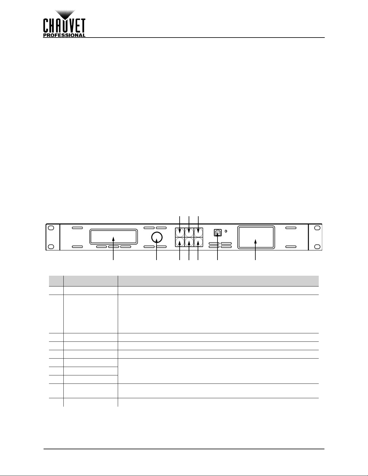
# NAME FUNCTION
1 Menu Display An interface for the menu options of the product
Press to enable the currently selected menu option or set the currently
SCROLL/ENTER
2
3 MENU Button Press to return to the previous menu level
4 SCALE Button Accesses the Scale menu. Can also be set to Black Out or Freeze .
5MAP ButtonAccesses the Map menu. Can also be set to Black Out or Freeze.
6 HDMI Button
8DVI Button
9
10 Preview Display Previews selected input source before output to video panel
Knob
USB Port
(Type B)
selected value into the selected function.
Turn clockwise to scroll down throug h the menu or increase a valu e when
in a function.
Turn counter-clockwise to scroll up through the menu or decrease a value
when in a function.
Select input source7SDI Button
Control port to interface with computer
3
VIP Drive 43s User Manual Rev. 1
Page 13
INTRODUCTION
1 23457 10
6
9
8
17.3 in
439 mm
2 in
51 mm
1.7 in
44 mm
1 in
25 mm
17.4 in
443 mm
12 in
305 mm
19 in
483 mm
9.8 in
248 mm
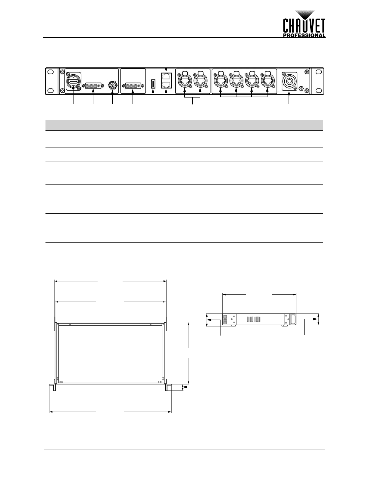
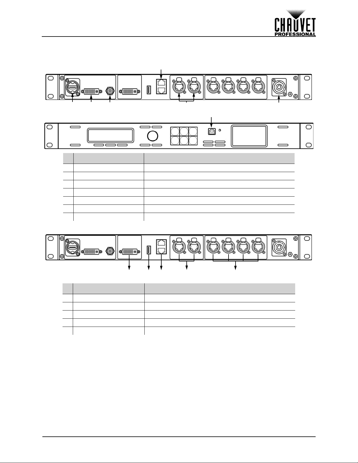
Rear Panel Overview
# NAME FUNCTION
1 HDMI Input HDMI video input
2 DVI Input DVI video input
3
4 DVI PREVIEW OUT For output preview on an external monitor
5 USB Port (Type A)
6
7
8
9
10
SD/HD/3G-SDI
Input
Ethernet Slave In
Port
Ethernet Slave Out
Port
Art-Net™ Through
Ports
Neutrik®
etherCON® Ports
Neutrik®
powerCON® Input
SDI video input
For connecting to a computer, or for USB cascade output (control only, no
video)
Reserved for future use
Reserved for future use
For Art-Net™ control
For output to LED video panels
Power input
Product Dimensions
VIP Drive 43s User Manual Rev. 1
4
Page 14
SETUP
3. SETUP
AC Power
Each VIP Drive 43s has an auto-ranging power supply that works with an input voltage range of 100 to 240
VAC, 50/60 Hz. To determine the power requirements for each VIP Drive 43s, refer to the label affixed to
the product. You can also refer to the Technical Specifications chart in this manual.
The listed current rating indicates the maximum current draw during normal operation. For more
information, download Sizing Circuit Breakers from the Chauvet website: www.chauvetprofessional.com
• Always connect the product to a protected circuit (circuit breaker or fuse). Make
sure the product has an appropriate electrical ground to avoid the risk of
electrocution or fire.
• T o eliminate unnecessary wear and improve its lifespan, during periods of non-use
completely disconnect the product from power via breaker or by unplugging it.
Never connect the product to a rheostat (variab le resistor ) or dimmer circuit , even if
the rheostat or dimmer channel serves only as a 0 to 100% switch.
AC Plug
The VIP Drive 43s comes with a power input cord terminated with a Neutrik® powerCON® connector on
one end and an Edison plug on the other end (U.S. market). If the power input cord that came with your
product has no plug, or if you need the change the plug, use the table below to wire the new plug.
CONNECTION WIRE (U.S.) WIRE (EUROPE) SCREW COLOR
AC Live Black Brown Yellow or Brass
AC Neutral White Blue Silver
AC Ground Green/Yellow Green/Yellow Green
.
Mounting
The VIP Drive 43s fits nicely on a standard 19” rack, or it can be placed on its rubber feet on a flat level
surface.
Signal Connections
The VIP Drive 43s uses the Linsn control protocol to send video signal to the connected panels. The VIP
Drive 43s has USB and Ethernet ports for interfacing with a computer, HDMI, SDI and DVI ports for video
input, as well as 4 Neutrik® etherCON® out ports, a DVI out port, 2 ethernet slave ports, and 2 ethernet
ports for Art-Net™ control.
Video Source Connection
You can link the VIP Drive 43s directly to a video source using a DVI connection, an HDMI connection, or
an SDI connection.
Computer Connection
You can link the VIP Drive 43s to a computer running video mapping software (such as LED Studio) using
a USB (type A or B) connection. This will provide control options for the VIP Drive 43s through a computer
interface. Download the LED Studio software and User Manual from www.chauvetvideo.com
Art-Net™ Connection
With Art-Net™, you can control the mapping and scaling, as well as the color balance and dimmer levels
for all connected panels. You can link the VIP Drive 43s to a controller using an ethernet connection. If
using other Art-Net™-compatible products with this product, you can control each individually with a single
controller. The Art-Net™ Values section provides detailed information regard ing the control channels.
Art-Net™ is an Ethernet protocol that uses TCP/IP which transfers a large amount of DMX512 data us ing
an Neutrik® etherCON® RJ45 connection over a large network. An Art-Net™ protocol document is
available from www.chauvetprofessional.com
Art-Net™ designed by and copyright Artistic Licence Holdings Ltd.
.
Preview Monitor Connection
Y o u can link the VIP Drive 43s to a monitor that will preview the LED output using a DVI cable plugged into
the PREVIEW OUT port. This port can also be set to forward the selected input signal to another product.
(See Preview DVI Port
)
.
5
VIP Drive 43s User Manual Rev. 1
Page 15
SETUP
2 3
4
51 6
7
1 2 3 54
Connection Diagrams
Input Connections Diagram
# CONNECTIONS PURPOSE
1 HDMI Link to an HDMI signal
2 DVI Link to a computer video output
3 SDI Link to a video device, such as a camera or a DVD player
4 Slave Ethernet Reserved for future use
5 Art-Net™ Ethernet Link to an Art-Net™ networ k
6 Neutrik® powerCON® Receive AC power
7 USB Type B Interface with a computer
Output Connections Diagram
# CONNECTIONS PURPOSE
1 DVI Preview monitor or another product
2 USB Type A Interface with a computer
3 Slave Ethernet Reserved for future use
4 Art-Net™ Ethernet Link to an Art-Net™ network
5 Neutrik® etherCON® LED video panels, such as the PVP X6IP from CHAUVET
VIP Drive 43s User Manual Rev. 1
6
Page 16
OPERATION
4. OPERATION
Control Panel Operation
See the Product Overview for a detailed description of the control panel.
Programming
Refer to the Menu Map to understand the menu options. The menu map shows the main level an d a
variable number of programming levels for each option.
• To access the menu from the Home Screen, press the <MENU> button.
• To scroll through the options on each level of the menu, turn the <SCROLL/ENTER> knob. Turn it
clockwise to scroll down, and turn it counter-clockwise to scroll up.
• Press the <SCROLL/ENTER> knob to select the highlighted option. This will take you to the next
programming level for that option, or it will highlight a value that can be edited.
• To increase a selected number value, turn the <SCROLL/ENTER> knob clockwise. To decrease a
selected number value, turn the <SCROLL/ENTER> knob counter-clockwise.
• Press <MENU> to exit to the previous main level.
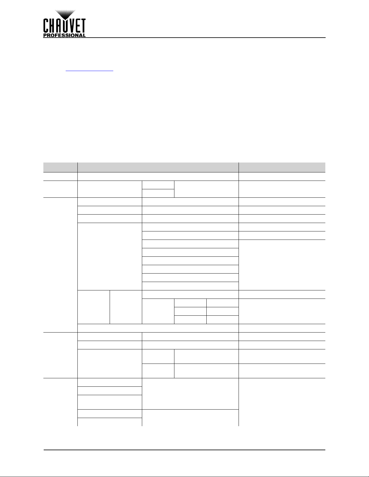
Menu Map
MAIN LEVEL PROGRAMMING LEVELS DESCRIPTION
Brightness 0–100 Controls total output level
Front Panel
Lock
Color
Adjustments
Ethernet
Backup
Front Panel Lock
Contrast 0–100 Sets contrast level
Saturation 0–100 Sets saturation level
Sharpness 0–100 Sets sharpness
Gamma
Color
T emperature
Art-Net Start Address 1–512 Sets Art-Net™ starting address
Art-Net Universe 0–255 Sets Art-Net™ universe
IP Address
Save Setup
Load Setup
Load Single From
Load all from USB
Save all to USB
Color
T emperature
USB
Off
On
Custom
Reset Resets color adjustments
Local IP
Address
Subnet
Mask
Input New Password
0000–9999
Linear Linear gamma correction
sRGB sRGB gamma correction
-1.2
1.2
-1.4
1.4
-1.6
1.6
Full RGB
Red Level 0–255
Green Level
Blue Level 0–255
_ _ _._ _ _._ _ _._ _ _
(000–255)
_ _ _._ _ _._ _ _._ _ _
(000–255)
Save1–10
All
0–255
Locks the control functions on
the front panel
Sets gamma correction level
Color temperature is full white
Sets maximum value of selected
color to control color
temperature
Sets IP address
Sets Subnet mask
Saves and loads configurations
<SCROLL/ENTER> knob to
confirm.
<MENU> button to cancel.
7
VIP Drive 43s User Manual Rev. 1
Page 17
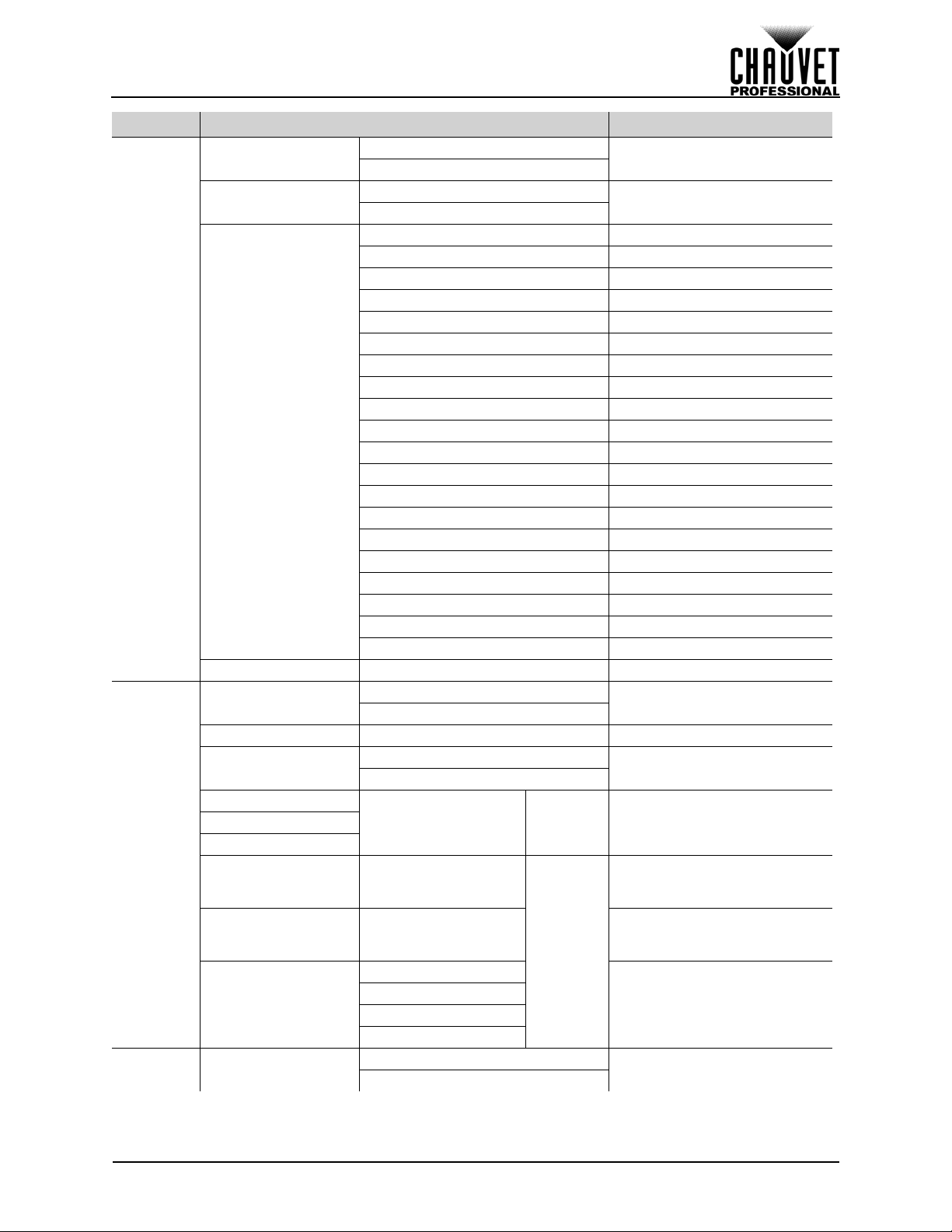
OPERATION
MAIN LEVEL PROGRAMMING LEVELS DESCRIPTION
Off
On
Off
On
Dissolve Fade dissolve
Cut Quick cut
Wipe Square In Square wipe inward
Wipe T_L In Top left wipe inward
Wipe T_L Top left wipe outward
Wipe T_R In Top right wipe inward
Wipe T_R
Wipe B_L In
Wipe B_L Bottom left wipe outward
Wipe B_R In
Wipe B_R Bottom right wipe outward
Wipe Left In Left wipe inward
Wipe Left Left wipe outward
Wipe Right In Right wipe inward
Wipe Right Right wipe outward
Wipe Top In Top wipe inward
Wipe Top Top wipe outward
Wipe Bottom In Bottom wipe inward
Wipe Bottom
Off
On
Off
1–10s
(Mode 19
Only)
(Mode 20
Red
Off
On
Only)
Enables/Disables Deinterlacing
Enables/Disables Image
Enhance
Square wipe outward
Top right wipe
Bottom left wipe inward
Bottom right wipe inward
Bottom wipe outward
Enables/disables test pattern
Turns off or sets switch time
Edits color of Test Pattern Mode
19
Sets number of horizontal steps
in gradient of Test Pattern Mode
20
Sets number of vertical steps in
gradient of Test Pattern Mode
20
Selects color of gradient of Test
Pattern Mode 20
Enables/disables Picture In
Picture
Image Enhance
Transition
Test
Pattern
PIP PIP
Deinterlace
Wipe Square Ou
Fade Type
Fade 0.0-3.0s (increments of 0.5s) Defines fade time
Test Pattern
Mode 1–20 Selects test pattern
Auto Switch
Red
Green
Blue
HOR STEP 2–64 (by doubles)
VER STEP 0–64 (increments of 4)
COLOR
0–255
Green
Blue
White
outward
VIP Drive 43s User Manual Rev. 1
8
Page 18
MAIN LEVEL PROGRAMMING LEVELS DESCRIPTION
Default Unchanged inputs
HDMI/DVI Input 1: DVI / Input 2: HDMI
HDMI/SDI Input 1: SDI / Input 2: HDMI
SDI/DVI Input 1: DVI / Input 2: SDI
SDI/HDMI Input 1: HDMI / Input 2: SDI
DVI/HDMI Input 1: HDMI / Input 2: DVI
DVI/SDI Input 1: SDI / Input 2: DVI
L+T Top left position
R+T Top right position
L+B Bottom left position
R+B
Cent Center position
L+R Left and right position
T+B Top and bottom position
INPUT1
INPUT2
Off Input 1 is the foreground
On Input 1 is the background
Auto Detects input format
RGB DVI Receive RGB DVI over HDMI
RGB HDMI Receive RGB HDMI
PREVIEW DVI Match format to PREVIEW OUT
FOLLOW Reserved for future use
CUSTOM
Auto Detects input format
PREVIEW DVI Match format to PREVIEW OUT
FOLLOW Reserved for future use
CUSTOM
Celsius
Fahrenheit
Off
On
Pre
Post
Preview DVI port outputs preview
Program DVI port outputs video
_ _ _ _x
_ _ _ _@
_ _
RGB DVI Receive RGB DVI
_ _ _ _x
_ _ _ _@
_ _
Bottom right position
Selects which input can be
scaled or changed with buttons
Sets the brightness of the menu
display
Define input parameters
Define input parameters
Selects temperature unit
Displays current product
temperature in selected unit
Enables/disables double-tap to
switch input sources
Selects original video or edited
video to preview
PIP (cont.)
OLED
Brightness
Video Input
T emperature
Advanced
Input
Position
Select
Swap
1–15
HDMI
DVI
SDI Auto Detects input format
Temperature
Temperature _ _ C/F
Firmware Version _._ _ Displays firmware version
Double-tap To
Preview Output
Preview DVI Port
Overwrite
Overwrite
Switch
EDID
Source
EDID
Source
OPERATION
9
VIP Drive 43s User Manual Rev. 1
Page 19
OPERATION
MAIN LEVEL PROGRAMMING LEVELS DESCRIPTION
Resets product to factory
defaults
Selects preset output resolution
and refresh rate
Sets width and height of video
output in proportion with
resolution
Enables/disables Auto Scale
Sets top and bottom zoom in
proportion
Advanced
(cont.)
Scale
Factory Reset
Scale Button navigates to Scale menu
Scale
Customized Button
Map
Output Format Standard
H Size 2–_ _ _ _ Sets width of video output
V Size 2–_ _ _ _ Sets height of video output
H/V Size 2–_ _ _ _
H Position 0–(H Size) Sets horizontal offset
V Position 0–(V Size) Sets vertical offset
Auto Scale
Reset Resets scale
Scale Mode Global Scale Reserved for future use
Top 0–_ _ _ _ Sets zoom from top
Bottom 0–_ _ _ _ Sets zoom from bottom
Top/Bottom 0–_ _ _ _
Left 0–_ _ _ _ Sets zoom from left
Right 0–_ _ _ _ Sets zoom from right
Advanced
Zoom/
Crop
Image
Blackout Button blacks out panels
Freeze Button freezes output
Map Button navigates to Map menu
Blackout Button blacks out panels
Freeze Button freezes output
800x600@60
1024x768@60
1024x768@75
1280x720@60
1280x720@50
1280x768@60
1280x800@60
1280x1024@60
1360x768@60
1366x768@60
1400x1050@60
1440x900@60
1600x1200@60
1680x1050@60
1920x1080@60
1920x1080@50
1920x1200@60
2048x1152@60
2560x812@60
2560x816@60
No
Yes
VIP Drive 43s User Manual Rev. 1
10
Page 20
MAIN LEVEL PROGRAMMING LEVELS DESCRIPTION
Sets left and right zoom in
proportion
Sets horizontal offset for ports 1
and 2
Sets vertical offset for ports 1
and 2
Sets horizontal offset for ports 3
and 4
Sets vertical offset for ports 3
and 4
Sets horizontal and vertical
positions of each port
Enter width and height of panel
assembly
Enter number of pixels per
panel
Enables/disables test grid
Selects color of gridGreen
Selects pattern of grid
Move test panel manually,
based on numbers mapped
Scale
(cont.)
Map
Zoom/
Advanced
(cont.)
Offset Settings
Position Settings
Port
Tutorial
Set Width
Test Grid
Crop
Image
(cont.)
Port 1–4
H Size
Port Port 1–4 Selects port to output test grid
Test Grid
Grid
Color
Type
Test
Patterns
Moving 1–255 Auto move speed, fast to slow
Left/Right 0–_ _ _ _
Center 0–_ _ _ _ Sets all zoom in proportion
Reset Resets zoom settings
Port 1/2 Offset X 0–65535
Port 1/2 Offset Y 0–65535
Port 3/4 Offset X 0–65535
Port 3/4 Offset Y 0–65535
Port 1 X 0–6553 5
Port 1 Y 0–65535
Port 2 X 0–6553 5
Port 2 Y 0–65535
Port 3 X 0–6553 5
Port 3 Y 0–65535
Port 4 X 0–6553 5
Port 4 Y 0–65535
Auto Auto detect panels
Wall Size:
Panel
Manual
Manual 2–_ _ _ _ Define width in pixels manually
Set Width Saves setting
Manual
Pixel
Count:
T otal Pixel
Res:
Auto Populates width from mapping
Off
On
Red
Yellow
Cross
Row
Column
Rectangle
Auto Move Test panel moves automatically
H Position 1–_ _
V Position 1–_ _
1–255x1–
255
1–999x
1–999
_ _ _ _ _ _ Displays total number of pixels
OPERATION
11
VIP Drive 43s User Manual Rev. 1
Page 21
OPERATION
MAIN LEVEL PROGRAMMING LEVELS DESCRIPTION
Red
Preset test panel colorsGreen
Test Grid
(cont.)
Wall Size WxH 1–255x1–255
Panel Pixel WxH 1–999x1–999 Sets number of pixels per panel
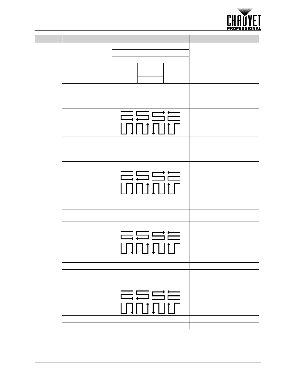
Connection Type Sets data flow path
Wall Size WxH 1–255x1–255
Panel Pixel WxH 1–999x1–999 Sets number of pixels per panel
Patterns
Color
Custom
Port 1 The following options for port 1
Save To Port Saves configuration settings
Port 2 The following options for port 2
Blue
Red
0–255 Custom test panel colorGreen
Blue
Sets number of panels
connected to port 1
Sets number of panels
connected to port 2
Map (cont.)
Connection Type Sets data flow path
Save To Port Saves configuration settings
Port 3 The following options for port 3
Wall Size WxH 1–255x1–255
Panel Pixel WxH 1–999x1–999 Sets number of pixels per panel
Connection Type Sets data flow path
Save To Port Saves configuration settings
Port 4 The following options for port 4
Wall Size WxH 1–255x1–255
Panel Pixel WxH 1–999x1–999 Sets number of pixels per panel
Connection Type Sets data flow path
Save To Port Saves configuration settings
Reset Reset mapping
Sets number of panels
connected to port 3
Sets number of panels
connected to port 4
VIP Drive 43s User Manual Rev. 1
12
Page 22
OPERATION
1
2
3
4
Operating Settings Configuration
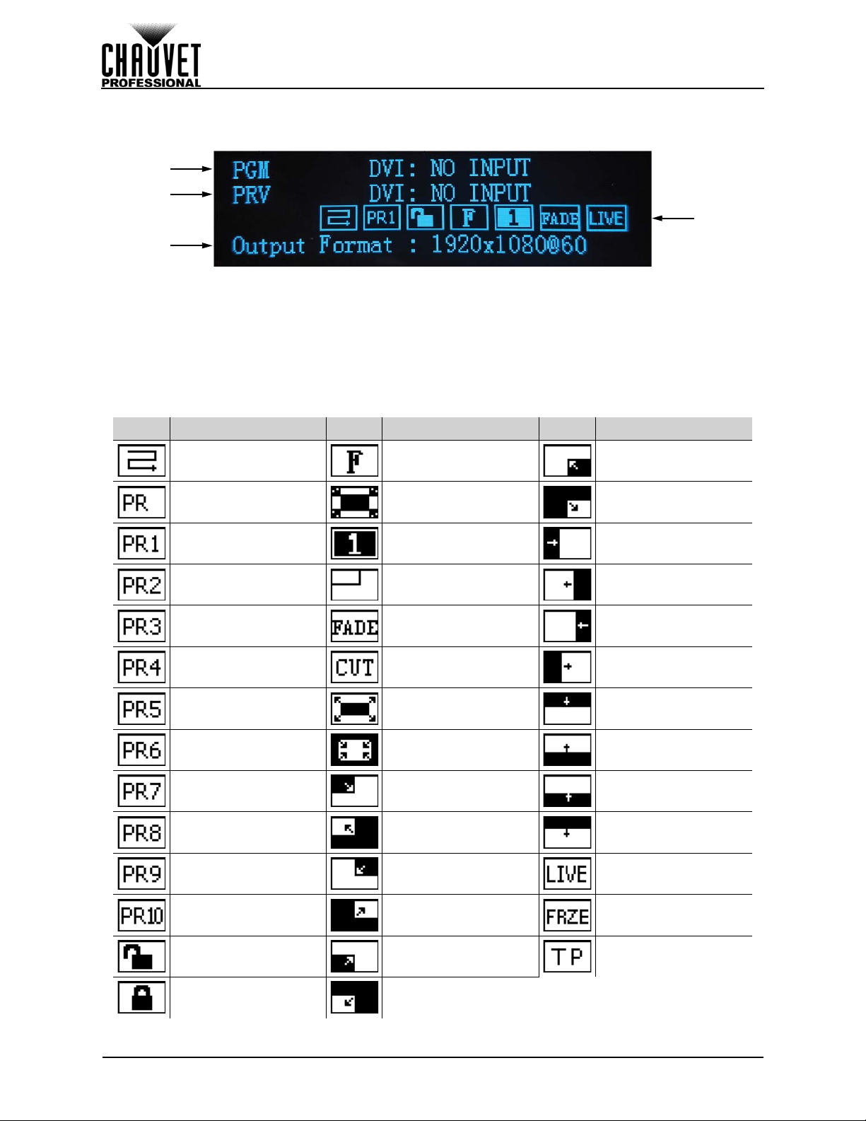
Home Screen
The VIP Drive 43s has a home screen that shows the current inp ut source s, resol utions, refresh rates, and
other operating settings. To see the home screen, wait until the display times out, or press <MENU>
repeatedly until it shows on the display. To access the main menu from the home screen, press <MENU>.
1. With PIP off: shows the currently selected input source, resolution, and refresh rate.
With PIP on: shows the Input 1 source. resolution, and refresh rate.
2. With PIP off: shows the currently previewed input source, resolution, and refresh rate.
With PIP on: shows the Input 2 source. resolution, and refresh rate.
3. Shows the output resolution and refresh rate.
4. Shows the status of the product, with the following icons:
ICON MEANING ICON MEANING ICON MEANING
Displays current Port 1
Data Flow
No save is loaded Auto-Scale is disabled
Save1 is loaded PIP is disabled
Save2 is loaded PIP is enabled
Save3 is loaded
Save4 is loaded Fade is set to Cut
Save5 is loaded
Save6 is loaded
Save7 is loaded
Save8 is loaded
Auto-Scale is enabled
Fade Type is set to
Dissolve
Fade Type is set to
Wipe Square In
Fade Type is set to
Wipe Square Ou
Fade Type is set to
Wipe T_L In
Fade Type is set to
Wipe T_L
Fade Type is set to
Wipe B_R In
Fade Type is set to
Wipe B_R
Fade Type is set to
Wipe Left In
Fade Type is set to
Wipe Left
Fade Type is set to
Wipe Right In
Fade Type is set to
Wipe Right
Fade Type is set to
Wipe Top In
Fade Type is set to
Wipe Top
Fade Type is set to
Wipe Bottom In
Fade Type is set to
Wipe Bottom
Save9 is loaded
Save10 is loaded
Display is not locked
Display is locked
13
Fade Type is set to
Wipe T_R In
Fade Type is set to
Wipe T_R
Fade Type is set to
Wipe B_L In
Fade Type is set to
Wipe B_L
VIP Drive 43s User Manual Rev. 1
Output is video
playback
Output is frozen
Output is test pattern
Page 23

OPERATION
Brightness
The brightness setting controls the total output level of the connected video panels.
1. Press <MENU> to access the menu.
2. Turn the <SCROLL/ENTER> knob until Brightness is selected.
3. Press the <SCROLL/ENTER> knob.
4. Turn the <SCROLL/ENTER> knob clockwise or counterclockwise to increase or decrease the
brightness, from 0–100.
5. Press the <SCROLL/ENTER> knob.
Front Panel Lock
The front panel interface of the VIP Drive 43s can be locked with a 4-digit passcode.
1. Press <MENU> to access the menu.
2. Turn the <SCROLL/ENTER> knob until Front Panel Lock is selected.
3. Press the <SCROLL/ENTER> knob. Front Panel Lock should be selected. Press the
<SCROLL/ENTER> knob again.
4. Turn the <SCROLL/ENTER> knob clockwise or counterclockwise to select Off or On.
5. Turn the <SCROLL/ENTER> knob clockwise or counterclockwise to increase or decrease the
first digit, from 0–9. Repeat with the second, third, and fourth digits. Select each digit carefully.
6. Press the <SCROLL/ENTER> knob.
7. Repeat step 5 to enter the same number, to confirm the new passcode.
8. Press the <SCROLL/ENTER> knob.
To unlock the front panel interface of the VIP Drive 43s:
1. Press <MENU>, <SCALE>, <MAP>, or the <SCROLL/ENTER> knob.
2. Use the <SCROLL/ENTER> knob to enter the passcode as it was set in the previous instruction.
Alternatively, entering 1 2 1 2 will also unlock the front panel interface.
3. Press the <SCROLL/ENTER> knob.
Color Adjustments
The Color Adjustments settings control output settings such as the contrast and color balance.
• Contrast controls the separation of different colors in the output.
• Saturation controls the intensity of all colors.
• Sharpness determines the amount of detail in the output.
• Color T emperature sets maximum values for each color, which affects the color temperature of the
video output.
• Gamma controls the gamma correction, which applies a non-linear function to the tonal ranges in
the video before output, which balances the brightness and darkness of the resulting video.
• Reset sets Color Adjustment settings to back to default.
To alter the Color Adjustment settings:
1. Press <MENU> to access the menu.
2. Turn the <SCROLL/ENTER> knob until Color Adjustments is selected.
3. Press the <SCROLL/ENTER> knob.
4. Use the <SCROLL/ENTER> knob to select from Contrast, Saturation, Sharpness, Gamma,
Color Temperature, or Reset.
5. For:
• Contrast, Saturation, or Sharpness:
a. Press the <SCROLL/ENTER> knob.
b. Turn the <SCROLL/ENTER> knob clockwise or counterclockwise to increase or
decrease the selected value, from 0–100.
c. Press the <SCROLL/ENTER> knob.
• Gamma:
a. Press the <SCROLL/ENTER> knob.
b. Use the <SCROLL/ENTER> knob to select from Linear, sRGB, -1.2, 1.2, -1.4, 1.4, -
1.6, or 1.6.
c. Press the <SCROLL/ENTER>
knob.
VIP Drive 43s User Manual Rev. 1
14
Page 24

OPERATION
• Color Temperature:
a. Press the <SCROLL/ENTER> knob.
b. Use the <SCROLL/ENTER> knob to select from Full RGB or Custom.
c. Press the <SCROLL/ENTER> knob.
d. If Custom was selected, use the <SCROLL/ENTER> knob to select from Red Level,
Green Level, or Blue Level.
e. Press the <SCROLL/ENTER> knob.
f. Turn the <SCROLL/ENTER> knob clockwise or counterclockwise to increase or
decrease the maximum value of the selected color, from 0–255.
g. Press the <SCROLL/ENTER> knob.
h. Repeat steps d-g until the color temperature is set as desired.
• Reset, press the <SCROLL/ENTER> knob.
Ethernet
The VIP Drive 43s can connect with an Art-Net™ controller to allow control of a majority of the product’s
settings.
The Ethernet settings control the Art-Net™ and network addressing for the product.
To access the Ethernet menu:
1. Press <MENU> to access the menu.
2. Turn the <SCROLL/ENTER> knob until Ethernet is selected.
3. Press the <SCROLL/ENTER> knob.
Art-Net™ Start Address
The VIP Drive 43s uses 95 channels, which makes the highest recommended starting address 418.
1. Access the Ethernet
2. Turn the <SCROLL/ENTER> knob until Art-Net Start Address is selected.
3. Press the <SCROLL/ENTER> knob.
4. Turn the <SCROLL/ENTER> knob clockwise or counterclockwise to increase or decrease the
address, from 1–512.
5. Press the <SCROLL/ENTER> knob.
Art-Net™ Universe
To select in which Art-Net™ universe the VIP Drive 43s is addressed:
1. Access the Ethernet
2. Turn the <SCROLL/ENTER> knob until Art-Net Universe is selected.
3. Press the <SCROLL/ENTER> knob.
4. Turn the <SCROLL/ENTER> knob clockwise or counterclockwise to increase or decrease the
universe address, from 0–255.
5. Press the <SCROLL/ENTER> knob.
IP Address
To set the IP address of the VIP Drive 43s:
1. Access the Ethernet
2. Turn the <SCROLL/ENTER> knob until IP Address is selected.
3. Press the <SCROLL/ENTER> knob.
4. Press the <SCROLL/ENTER> knob again.
5. Turn the <SCROLL/ENTER> knob clockwise or counterclockwise to increase or decrease the
first digit, from 000–255.
6. Press the <SCROLL/ENTER> knob.
7. Turn the <SCROLL/ENTER> knob clockwise or counterclockwise to increase or decrease the
next digit, from 000–255.
8. Repea t step s 6 an d 7 twic e.
9. Press the <SCROLL/ENTER> knob.
menu.
menu.
menu.
15
VIP Drive 43s User Manual Rev. 1
Page 25
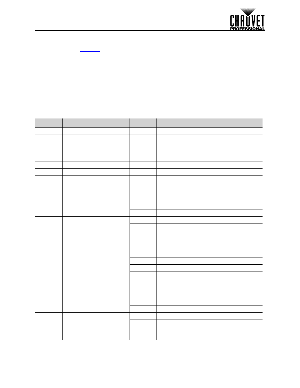
OPERATION
Subnet Mask
To set the subnet mask of the VIP Drive 43s:
1. Access the Ethernet
2. Turn the <SCROLL/ENTER> knob until Subnet Mask is selected.
3. Press the <SCROLL/ENTER> knob.
4. Press the <SCROLL/ENTER> knob again.
5. Turn the <SCROLL/ENTER> knob clockwise or counterclockwise to increase or decrease the
first digit, from 000–255.
6. Press the <SCROLL/ENTER> knob.
7. Turn the <SCROLL/ENTER> knob clockwise or counterclockwise to increase or decrease the
next digit, from 000–255.
8. Repea t step s 6 an d 7 twic e.
9. Press the <SCROLL/ENTER> knob.
Art-Net™ Values
CHANNEL FUNCTION VALUE PERCENT/SETTING
1 Master Dimmer 000 255 0–100%
2 Port 1 Dimmer 000
3 Port 2 Dimmer 000
4 Port 3 Dimmer 000
5 Port 4 Dimmer 000
6 Contrast 000
7 Saturation 000
8Control
9Test Patterns
10 HDMI Trigger/Dimmer
11 DVI Trigger/Dimmer
12 SDI Trigger/Dimmer
menu.
255 0–100%
255 0–100%
255 0–100%
255 0–100%
255 0–100%
255 0–100%
000
010 No function
011
020 Soft reset
021
189 Reserved for future use
190
195 Enable Map functions
196
200 Factory reset
201
255 Reserved for future use
000
009 No function
010
019 Test pattern 1
020
029 Test pattern 2
030
039 Test pattern 3
040
049 Test pattern 4
050
059 Test pattern 5
060
069 Test pattern 6
070
079 Test pattern 7
080
089 Test pattern 8
090
099 Test pattern 9
100
109 Test pattern 10
110
255 No function
000 No function
001
255 Selects HDMI input; Dimmer 1–100%
000 No function
001
255 Selects DVI input; Dimmer 1–100%
000 No function
001
255 Selects SDI input; Dimmer 1–100%
VIP Drive 43s User Manual Rev. 1
16
Page 26

Art-Net™ Values (cont.)
CHANNEL FUNCTION VALUE PERCENT/SETTING
13 Red Balance 000 255 0–100%
14 Green Balance 000
15 Blue Balance 000
16 Input 1 Horizontal Offset 000
17
Input 1 Fine Horizontal
Offset
18 Input 1 Vertical Offset 000
19 Input 1 Fine Vertical Offset 000
20 Input 1 Horizontal Scaling 000
21
Input 1 Fine Horizontal
Scaling
22 Input 1 Vertical Scaling 000
23 Input 1 Fine Vertical Scaling 000
24 Input 1 Center Zoom 000
25 Input 1 Fine Center Zoom 000
26 Input 1 Left/Right Zoom 000
27
Input 1 Fine Left/Right
Zoom
28 Input 1 Top/Bottom Zoom 000
29
Input 1 Fine Top/Bottom
Zoom
30 Input 2 Horizontal Offset 000
31
Input 2 Fine Horizontal
Offset
32 Input 2 Vertical Offset 000
33 Input 2 Fine Vertical Offset 000
34 Input 2 Horizontal Scaling 000
35
Input 2 Fine Horizontal
Scaling
36 Input 2 Vertical Scaling 000
37 Input 2 Fine Vertical Scaling 000
38 Input 2 Center Zoom 000
39 Input 2 Fine Center Zoom 000
40 Input 2 Left/Right Zoom 000
41
Input 2 Fine Left/Right
Zoom
42 Input 2 Top/Bottom Zoom 000
43
Input 2 Fine Top/Bottom
Zoom
44 Port 1/2 Horizontal Offset 000
45
Port 1/2 Fine Horizontal
Offset
46 Port 1/2 Vertical Offset 000
47 Port 1/2 Fine Vertical Offset 00 0
48 Port 3/4 Horizontal Offset 000
49
Port 3/4 Fine Horizontal
Offset
50 Port 3/4 Vertical Offset 000
255 0–100%
255 0–100%
255 0–100%, left to right
000
255 0–100%, left to right
255 0–100%, top to bottom
255 0–100%, top to bottom
255 0–100%, narrow to wide
000
255 0–100%, narrow to wide
255 0–100%, short to tall
255 0–100%, short to tall
255 0–100%, far to close
255 0–100%, far to close
255 0–100%, far to close
000
255 0–100%, far to close
255 0–100%, far to close
000
255 0–100%, far to close
255 0–100%, left to right
000
255 0–100%, left to right
255 0–100%, top to bottom
255 0–100%, top to bottom
255 0–100%, narrow to wide
000
255 0–100%, narrow to wide
255 0–100%, short to tall
255 0–100%, short to tall
255 0–100%, far to close
255 0–100%, far to close
255 0–100%, far to close
000
255 0–100%, far to close
255 0–100%, far to close
000
255 0–100%, far to close
255 0–100%, left to right
000
255 0–100%, left to right
255 0–100%, top to bottom
255 0–100%, top to bottom
255 0–100%, left to right
000
255 0–100%, left to right
255 0–100%, top to bottom
OPERATION
17
VIP Drive 43s User Manual Rev. 1
Page 27
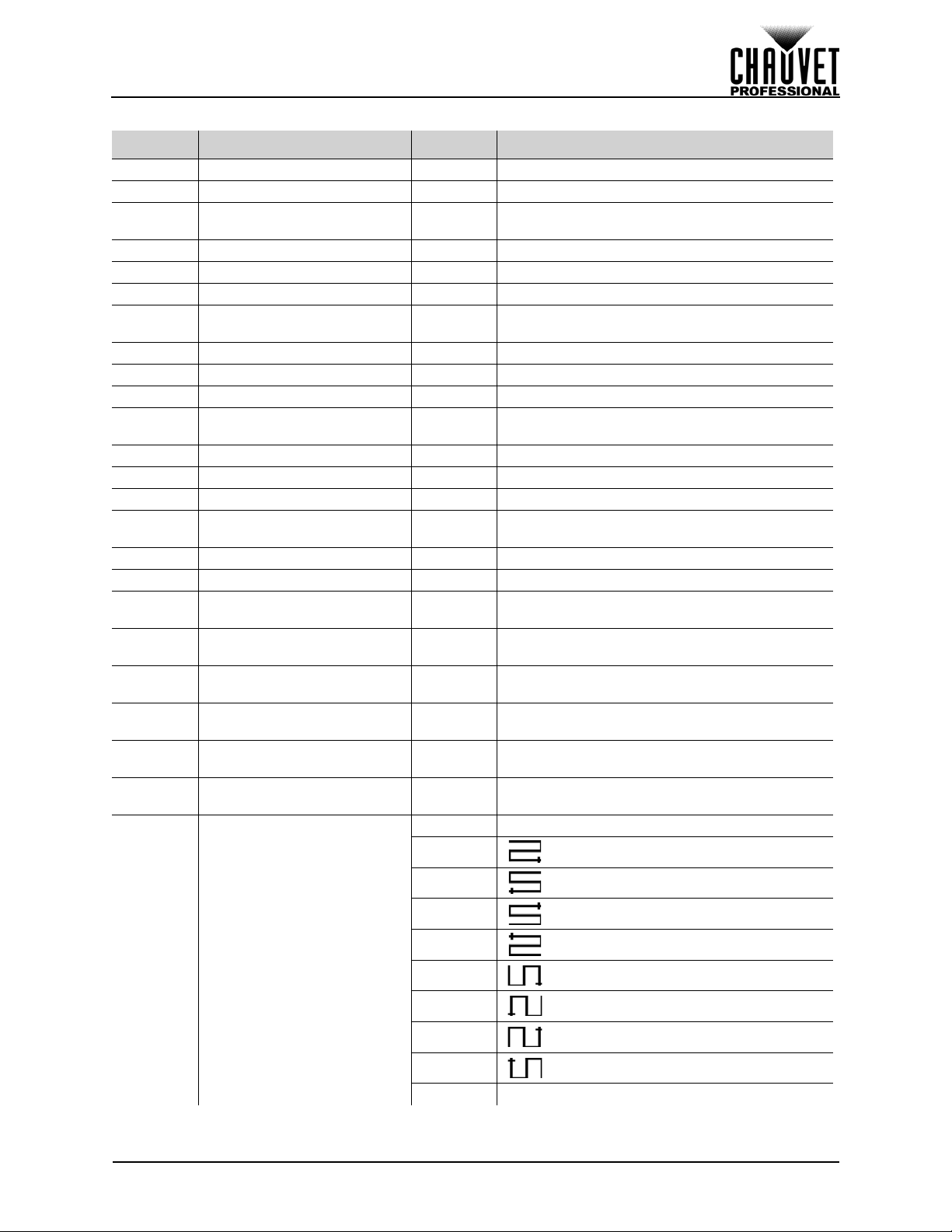
OPERATION
Art-Net™ Values (cont.)
CHANNEL FUNCTION VALUE PERCENT/SETTING
51 Port 3/4 Fine Vertical Offset 00 0 255 0–100%, top to bottom
52 Port 1 Horizontal Offset 000
53
Port 1 Fine Horizontal
Offset
54 Port 1 Vertical Offset 000
55 Port 1 Fine Vertical Offset 000
56 Port 2 Horizontal Offset 000
57
Port 2 Fine Horizontal
Offset
58 Port 2 Vertical Offset 000
59 Port 2 Fine Vertical Offset 000
60 Port 3 Horizontal Offset 000
61
Port 3 Fine Horizontal
Offset
62 Port 3 Vertical Offset 000
63 Port 3 Fine Vertical Offset 000
64 Port 4 Horizontal Offset 000
65
Port 4 Fine Horizontal
Offset
66 Port 4 Vertical Offset 000
67 Port 4 Fine Vertical Offset 000
68
69
70
71
72
73
Port 1 Horizontal Panel
Quantity
Port 1 Vertical Panel
Quantity
Port 1 Horizontal Pixels Per
Panel
Port 1 Fine Horizontal
Pixels Per Panel
Port 1 Vertical Pixels Per
Panel
Port 1 Fine Vertical Pixels
Per Panel
255 0–100%, left to right
000
255 0–100%, left to right
255 0–100%, top to bottom
255 0–100%, top to bottom
255 0–100%, left to right
000
255 0–100%, left to right
255 0–100%, top to bottom
255 0–100%, top to bottom
255 0–100%, left to right
000
255 0–100%, left to right
255 0–100%, top to bottom
255 0–100%, top to bottom
255 0–100%, left to right
000
255 0–100%, left to right
255 0–100%, top to bottom
255 0–100%, top to bottom
000
255 1 to maximum (Ch. 8 must be 190–195)
000
255 1 to maximum (Ch. 8 must be 190–195)
000
255 1 to 900 (Ch. 8 must be 190–195)
000
255 1 to 99 (Ch. 8 must be 190–195)
000
255 1 to 900 (Ch. 8 must be 190–195)
000
255 1 to 99 (Ch. 8 must be 190–195)
000
009 No function
019
010
74
Port 1 Data Flow (Ch. 8 must
be 190–195)
VIP Drive 43s User Manual Rev. 1
029
020
039
030
049
040
059
050
069
060
079
070
089
080
255 Reserved for future use
090
18
Page 28
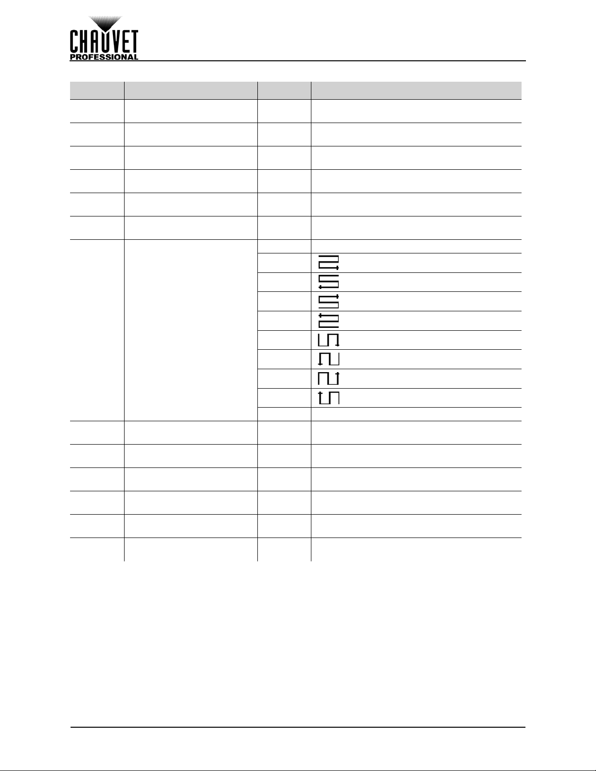
Art-Net™ Values (cont.)
CHANNEL FUNCTION VALUE PERCENT/SETTING
75
76
77
78
79
80
81
Port 2 Horizontal Panel
Quantity
Port 2 Vertical Panel
Quantity
Port 2 Horizontal Pixels Per
Panel
Port 2 Fine Horizontal
Pixels Per Panel
Port 2 Vertical Pixels Per
Panel
Port 2 Fine Vertical Pixels
Per Panel
Port 2 Data Flow (Ch. 8 must
be 190–195)
000 255 1 to maximum (Ch. 8 must be 190–195)
000
255 1 to maximum (Ch. 8 must be 190–195)
000
255 1 to 900 (Ch. 8 must be 190–195)
000
255 1 to 99 (Ch. 8 must be 190–195)
000
255 1 to 900 (Ch. 8 must be 190–195)
000
255 1 to 99 (Ch. 8 must be 190–195)
000
009 No function
019
010
029
020
039
030
049
040
059
050
OPERATION
82
83
84
85
86
87
Port 3 Horizontal Panel
Quantity
Port 3 Vertical Panel
Quantity
Port 3 Horizontal Pixels Per
Panel
Port 3 Fine Horizontal
Pixels Per Panel
Port 3 Vertical Pixels Per
Panel
Port 3 Fine Vertical Pixels
Per Panel
069
060
079
070
089
080
255 Reserved for future use
090
000
255 1 to maximum (Ch. 8 must be 190–195)
000
255 1 to maximum (Ch. 8 must be 190–195)
000
255 1 to 900 (Ch. 8 must be 190–195)
000
255 1 to 99 (Ch. 8 must be 190–195)
000
255 1 to 900 (Ch. 8 must be 190–195)
000
255 1 to 99 (Ch. 8 must be 190–195)
19
VIP Drive 43s User Manual Rev. 1
Page 29
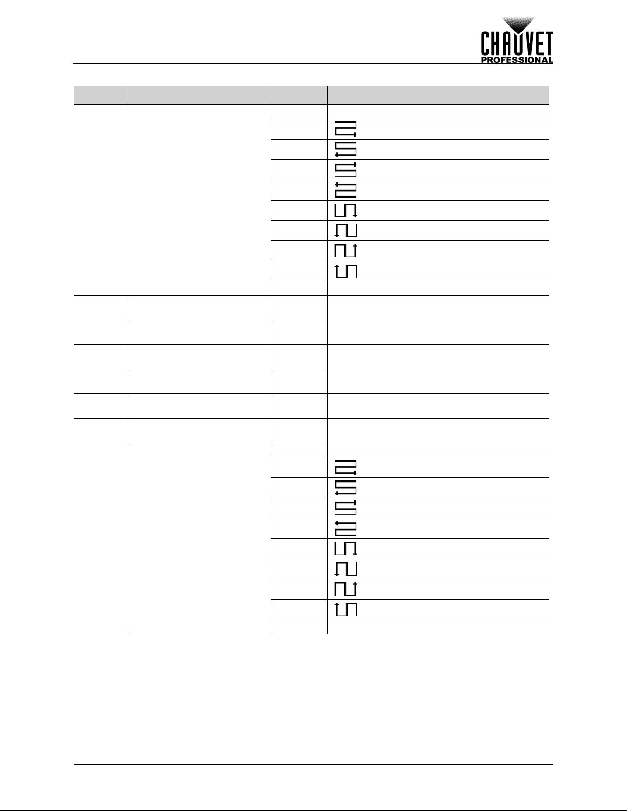
OPERATION
Art-Net™ Values (cont.)
CHANNEL FUNCTION VALUE PERCENT/SETTING
000
009 No function
019
010
029
020
030
039
049
88
89
90
91
92
93
94
Port 3 Data Flow (Ch. 8 must
be 190–195)
Port 4 Horizontal Panel
Quantity
Port 4 Vertical Panel
Quantity
Port 4 Horizontal Pixels Per
Panel
Port 4 Fine Horizontal
Pixels Per Panel
Port 4 Vertical Pixels Per
Panel
Port 4 Fine Vertical Pixels
Per Panel
040
059
050
069
060
079
070
089
080
255 Reserved for future use
090
000
255 1 to maximum (Ch. 8 must be 190–195)
000
255 1 to maximum (Ch. 8 must be 190–195)
000
255 1 to 900 (Ch. 8 must be 190–195)
000
255 1 to 99 (Ch. 8 must be 190–195)
000
255 1 to 900 (Ch. 8 must be 190–195)
255 1 to 99 (Ch. 8 must be 190–195)
000
000
009 No function
019
010
029
020
039
030
049
95
Port 4 Data Flow (Ch. 8 must
be 190–195)
040
059
050
069
060
079
070
089
080
255 Reserved for future use
090
Backup
The VIP Drive 43s can save up to 10 different settings configurations to be recalled at any time or loaded
onto another VIP Drive 43s.
To access the Backup menu:
1. Press <MENU> to access the menu.
2. Turn the <SCROLL/ENTER> knob until Backup is selected.
3. Press the <SCROLL/ENTER> knob.
VIP Drive 43s User Manual Rev. 1
20
Page 30

OPERATION
Save Configuration
To save the current settings configuration so it can be recalled at any time:
1. Access the Backup
2. Turn the <SCROLL/ENTER> knob until Save Setup is selected.
3. Press the <SCROLL/ENTER> knob.
4. Turn the <SCROLL/ENTER> knob clockwise or counter-clockwise to select from Save1–10.
5. Press the <SCROLL/ENTER> knob to save the current configuration to the selected save file.
6. Press <MENU> to exit.
Load Configuration
To load a previously saved configuration:
1. Access the Backup
2. Turn the <SCROLL/ENTER> knob until Load Setup is selected.
3. Press the <SCROLL/ENTER> knob.
4. Turn the <SCROLL/ENTER> knob clockwise or counter-clockwise to select from Save1–10.
5. Press the <SCROLL/ENTER> knob to load the selected save file into the product’s settings.
6. Press <MENU> to exit.
Load One Configuration from USB
To save the current settings configuration from a USB-connected VIP Drive 43s:
1. Access the Backup
2. Turn the <SCROLL/ENTER> knob until Load Single From USB is selected.
3. Press the <SCROLL/ENTER> knob.
4. Turn the <SCROLL/ENTER> knob clockwise or counter-clockwise to select from Save1–10.
5. Press the <SCROLL/ENTER> knob to copy the connected product’s settings into the selected
save file.
6. Press <MENU> to exit.
Load All from USB
To copy all save files from a USB-connected VIP Drive 43s:
1. Access the Backup
2. Turn the <SCROLL/ENTER> knob until Load all from USB is selected.
3. Press the <SCROLL/ENTER> knob. The display will show All as the only option.
4. Press the <SCROLL/ENTER> knob to copy all of the connected product’s save files.
5. Press <MENU> to exit.
Save All to USB
To copy all save files to a USB-connected VIP Drive 43s:
1. Access the Backup
2. Turn the <SCROLL/ENTER> knob until Save all to USB is selected.
3. Press the <SCROLL/ENTER> knob. The display will show All as the only option.
4. Press the <SCROLL/ENTER> knob to copy all save files to the connected product.
5. Press <MENU> to exit.
Transition
The Transition settings control deinterlacing and image enhancing, and determine the way the VIP Drive
43s will transition from one input source to another.
To access the Transition menu:
1. Press <MENU> to access the menu.
2. Turn the <SCROLL/ENTER> knob until Transition is selected.
3. Press the <SCROLL/ENTER> knob.
Deinterlacing
Deinterlacing is the process of converting an interlaced video signal (two fields of images per frame,
traditionally for analog systems) into a progressive signal (a single image per frame). This option can be
enabled for interlaced signals, or disabled for progressive signals.
1. Access the Transition
2. Turn the <SCROLL/ENTER> knob until Deinterlace is selected.
3. Press the <SCROLL/ENTER> knob.
4. Turn the <SCROLL/ENTER> knob clockwise or counterclockwise to select Off or On.
5. Press the <SCROLL/ENTER> knob.
menu.
menu.
menu.
menu.
menu.
menu.
21
VIP Drive 43s User Manual Rev. 1
Page 31

OPERATION
Image Enhance
The Image Enhance setting corrects for data loss or corrup tion, often due to cables (damage d, poor quality
or too long) or radio frequency interference. With Image Enhance enabled, the VIP Drive 43s will detect
any errors and correct them before the signal reaches the connected panel assembly.
1. Access the Transition
2. Turn the <SCROLL/ENTER> knob until Image Enhance is selected.
3. Press the <SCROLL/ENTER> knob.
4. Turn the <SCROLL/ENTER> knob clockwise or counterclockwise to select Off or On.
5. Press the <SCROLL/ENTER> knob.
Fade Type
The Fade Type setting determines the way the VIP Drive 43s will transition from one image source to
another.
1. Access the Transition
2. Turn the <SCROLL/ENTER> knob until Fade Type is selected.
3. Press the <SCROLL/ENTER> knob.
4. Turn the <SCROLL/ENTER> knob clockwise or counterclockwise to select from:
• Dissolve (The first image fades into the second),
• Cut (No transition effect),
• Wipe Square In (The second image wipes in from all sides, covering the first),
• Wipe Square Ou (The first im ag e wip es ou t fro m the center, revealing the second),
• Wipe T_L In (The second image wipes in from the top left, covering the first),
• Wipe T_L (The first image wipes out to the top left, revealing the second),
• Wipe T_R In (The second image wipes in from the top right, covering the first),
• Wipe T_R (The first image wipes out to the top right, revealing the second),
• Wipe B_L In (The second image wipes in from the bottom left, covering the first),
• Wipe B_L (The first image wipes out to the bottom left, revealing the second),
• Wipe B_R In (The second image wipes in from the bottom right, covering the first),
• Wipe B_R (The first image wipes out to the bottom right, revealing the second),
• Wipe Left In (The second image wipes in from the left, covering the first),
• Wipe Left (The first image wipes out to the left, revealing the second),
• Wipe Right In (The second image wipes in from the right, covering the first),
• Wipe Right (The first image wipes out to the right, revealing the second),
• Wipe Top In (The second image wipes in from the top, covering the first),
• Wipe Top (The first image wipes out to the top, revealing the second),
• Wipe Bottom In (The second image wipes in from the bottom, covering the first),
or
• Wipe Bottom (The first image wipes out to the bottom, revealing the second).
5. Press the <SCROLL/ENTER> knob.
Fade Time
The Fade Time setting determines the delay between selecting an input source and the transition.
1. Access the Transition
2. Turn the <SCROLL/ENTER> knob until Fade is selected.
3. Press the <SCROLL/ENTER> knob.
4. Turn the <SCROLL/ENTER> knob clockwise or counterclockwise to select from 0.0s, 0.5s, 1.0s,
1.5s, 2.0s, 2.5s, or 3.0s.
5. Press the <SCROLL/ENTER> knob.
menu.
menu.
menu.
VIP Drive 43s User Manual Rev. 1
22
Page 32

OPERATION
Test Pattern
The Test Pattern function sends one of 20 patterns to the connected panel asse mbly to test the panels, the
connections, and the mapping.
To access the Test Pattern menu:
1. Press <MENU> to access the menu.
2. Turn the <SCROLL/ENTER> knob until Test Pattern is selected.
3. Press the <SCROLL/ENTER> knob.
To enable or disable the Test Pattern function:
1. Access the Test Pattern
2. Turn the <SCROLL/ENTER> knob until Test Pattern is selected.
3. Press the <SCROLL/ENTER> knob.
4. Turn the <SCROLL/ENTER> knob clockwise or counterclockwise to select Off or On.
5. Press the <SCROLL/ENTER> knob.
Test Pattern Mode
To select which pattern is sent to the connected panel assembly:
1. Access the Test Pattern
2. Turn the <SCROLL/ENTER> knob until Mode is selected.
3. Press the <SCROLL/ENTER> knob.
4. Turn the <SCROLL/ENTER> knob clockwise or counterclockwise to select from 1–20.
5. Press the <SCROLL/ENTER> knob.
Some panel configurations may be too small to view Test Patterns 3–10 and 13
properly.
menu.
menu.
Test Pattern Mode 19
With Test Pattern Mode 19 selected, after pressing the <SCROLL/ENTER> knob, 3 new options will
appear. Test Pattern Mode 19 will only output to the connected panels after one of these options is
selected.
After selecting Test Pattern Mode 19:
1. Turn the <SCROLL/ENTER> knob until Red, Green, or Blue is selected.
2. Press the <SCROLL/ENTER> knob.
3. Turn the <SCROLL/ENTER> knob clockwise or counterclockwise to increase or decrease the
color value, from 0–255.
4. Press the <SCROLL/ENTER> knob.
Test Pattern Mode 20
With Test Pattern Mode 20 selected, after pressing the <SCROLL/ENTER> knob, 3 new options will
appear:
• Horizontal Gradient Steps
1. Turn the <SCROLL/ENTER> knob until HOR STEP is selected.
2. Press the <SCROLL/ENTER> knob.
3. Turn the <SCROLL/ENTER> knob clockwise or counterclockwise to increase or decrease
the number of horizontal steps in the grad ie nt, from 2, 4, 8, 16, 32, or 64.
4. Press the <SCROLL/ENTER> knob.
• Vertical Gradient Steps
1. Turn the <SCROLL/ENTER> knob until VER STEP is selected.
2. Press the <SCROLL/ENTER> knob.
3. Turn the <SCROLL/ENTER> knob clockwise or counterclockwise to increase or decrease
the number of vertical steps in the gradient, from 0, 4, 8, 12, 16, 20, 24, 28, 32, 36, 40, 44,
48, 52, 56, 60, or 64.
4. Press the <SCROLL/ENTER> knob.
•Color
1. Turn the <SCROLL/ENTER> knob until COLOR is selected.
2. Press the <SCROLL/ENTER> knob.
3. Turn the <SCROLL/ENTER> knob to select the color of the gradient, from Red, Green,
Blue, or White.
4. Press the <SCROLL/ENTER> knob.
23
VIP Drive 43s User Manual Rev. 1
Page 33

OPERATION
Auto Switch
The Auto Switch function cycles through all of the test pattern modes at an adjustable rate.
1. Access the Test Pattern
2. Turn the <SCROLL/ENTER> knob until Auto Switch is selected.
3. Press the <SCROLL/ENTER> knob.
4. Turn the <SCROLL/ENTER> knob clockwise or counterclockwise to select from Off, or 1–10s.
5. Press the <SCROLL/ENTER> knob.
Picture In Picture
The PIP (Picture In Picture) function allows 2 input sources to be displayed on the connected panel
assembly at once.
To access the PIP menu:
1. Press <MENU> to access the menu.
2. Turn the <SCROLL/ENTER> knob until PIP is selected.
3. Press the <SCROLL/ENTER> knob.
To enable or disable PIP:
1. Access the PIP
2. Turn the <SCROLL/ENTER> knob until PIP is selected.
3. Press the <SCROLL/ENTER> knob.
4. Turn the <SCROLL/ENTER> knob clockwise or counterclockwise to select Off or On.
5. Press the <SCROLL/ENTER> knob.
Input Selection
There are two methods of selecting the inputs in PIP mode. For button options, see Input Mode.
To select both inputs through the menu:
1. Access the PIP
2. Turn the <SCROLL/ENTER> knob until Input is selected.
3. Press the <SCROLL/ENTER> knob.
4. Turn the <SCROLL/ENTER> knob clockwise or counterclockwise to select from:
• Default (Input settings will be unchanged),
• HDMI/DVI (Input 1: DVI, Input 2: HDMI),
• HDMI/SDI (Input 1: SDI, Input 2: HDMI),
• SDI/DVI (Input 1: DVI, Input 2: SDI),
• SDI/HDMI (Input 1: HDMI, Input 2: SDI),
• DVI/HDMI (Input 1: HDMI, Input 2: DVI),
or
• DVI/SDI (Input 1: SDI, Input 2: DVI).
5. Press the <SCROLL/ENTER> knob.
Position
The position setting determines where on the connected panel assembly the input designated as PIP will
be displayed.
1. Access the PIP
2. Turn the <SCROLL/ENTER> knob until Position is selected.
3. Press the <SCROLL/ENTER> knob.
4. Turn the <SCROLL/ENTER> knob clockwise or counterclockwise to select from:
• L+T (Top left of the panel assembly),
• R+T (Top right of the panel assembly),
• L+B (Bottom left of the panel assemb ly),
• R+B (Bottom right of the panel assembly),
• Cent (Center of the panel assembly),
• L+R (One input on the left, the other on the right of the panel assembly),
or
• T+B (One input on the top, the other on the bottom of the panel assembly).
5. Press the <SCROLL/ENTER> knob.
menu.
menu.
menu.
menu.
VIP Drive 43s User Manual Rev. 1
24
Page 34

OPERATION
Input Mode
Selecting INPUT 1 or INPUT 2 under PIP de termines which input can be scaled, as well as which input can
be changed by pressing one of the buttons on the front panel.
1. Access the PIP
2. Turn the <SCROLL/ENTER> knob until Select is selected.
3. Press the <SCROLL/ENTER> knob.
4. Turn the <SCROLL/ENTER> knob clockwise or counterclockwise to select INPUT 1 or INPUT 2.
5. Press the <SCROLL/ENTER> knob.
Press <HDMI>, <SDI>, or <DVI> to change the source of the selected input.
Swap Inputs
The swap function switches which input is in the foreground and which is in the background.
1. Access the PIP
2. Turn the <SCROLL/ENTER> knob until Swap is selected.
3. Press the <SCROLL/ENTER> knob.
4. Turn the <SCROLL/ENTER> knob clockwise or counterclockwise to select Off (INPUT 1 is in the
foreground) or On (INPUT 2 is in the foreground).
5. Press the <SCROLL/ENTER> knob.
Display Brightness
To alter the brightness of the menu display:
1. Press <MENU> to access the menu.
2. Turn the <SCROLL/ENTER> knob until OLED Brightness is selected.
3. Press the <SCROLL/ENTER> knob.
4. Turn the <SCROLL/ENTER> knob clockwise or counterclockwise to increase or decrease the
display brightness, from 1–15.
5. Press the <SCROLL/ENTER> knob.
Video Input
The Video Input settings determine the method the VIP Drive 43s communicates with the video sources.
The product can detect the format of an incoming signal automatically, or can be overwritten with a specific
format.
1. Press <MENU> to access the menu.
2. Turn the <SCROLL/ENTER> knob until Video Input is selected.
3. Press the <SCROLL/ENTER> knob.
4. Turn the <SCROLL/ENTER> knob clockwise or counterclockwise to select from HDMI, DVI, or
HD-SDI.
5. Press the <SCROLL/ENTER> knob.
6. Turn the <SCROLL/ENTER> knob clockwise or counterclockwise to select either Auto or
Overwrite (not available for HD-SDI).
7. Press the <SCROLL/ENTER> knob. If Auto was selected, the format of the input signal will be
displayed. If Overwrite was selected, continue.
8. The display will read EDID Source. Press the <SCROLL/ENTER> knob.
9. Turn the <SCROLL/ENTER> knob clockwise or counterclockwise to select from RGB DVI, RGB
HDMI, PREVIEW DVI, FOLLOW, or CUSTOM.
10. Press the <SCROLL/ENTER> knob.
11. For:
• RGB DVI (for an RGB DVI signal over DVI or HDMI), RGB HDMI (only available for HDMI),
PREVIEW DVI (to copy the format of being output through the PREVIEW OUT port), or
FOLLOW (reserved for future use), press the <SCROLL/ENTER> knob.
• CUSTOM, set the resolution and refresh rate:
a. Turn the <SCROLL/ENTER> knob clockwise or counterclockwise to increase or
b. Press the <SCROLL/ENTER> knob.
c. Repeat with each digit until the resolution and refresh rate are set as desired.
menu.
menu.
decrease the value of the firs t digit. Select carefully.
25
VIP Drive 43s User Manual Rev. 1
Page 35

OPERATION
Temperature
The Temperature option displays the current product temperature in either Celsius or Fahrenheit.
1. Press <MENU> to access the menu.
2. Turn the <SCROLL/ENTER> knob until Temperature is selected.
3. Press the <SCROLL/ENTER> knob. The current product temperature will be displayed.
To select the unit of temperature to display:
4. Press the <SCROLL/ENTER> knob again.
5. Turn the <SCROLL/ENTER> knob clockwise or counterclockwise to select from Celsius or
Fahrenheit.
6. Press the <SCROLL/ENTER> knob.
Advanced
The Advanced menu includes button controls, port assignment, a factory reset option, and preset output
formats.
To access the Advanced menu:
1. Press <MENU> to access the menu.
2. Turn the <SCROLL/ENTER> knob until Advanced is selected.
3. Press the <SCROLL/ENTER> knob.
Firmware Version
To view the firmware version of the product, access the Advanced menu. The first line will display the
firmware version.
Double-tap To Switch
The Double-tap To Switch option determines how many button presses are required to switch input
sources.
1. Access the Advanced
2. Turn the <SCROLL/ENTER> knob until Double-tap To Switch is selected.
3. Press the <SCROLL/ENTER> knob.
4. Turn the <SCROLL/ENTER> knob clockwise or counterclockwise to select Off (One press will
switch input sources) or On (Button must be pressed twice to switch input sources).
5. Press the <SCROLL/ENTER> knob.
Preview Output
The Preview Output setting determines whether the pr eview display shows the video signal befo re or after
scaling.
1. Access the Advanced
2. Turn the <SCROLL/ENTER> knob until Preview Output is selected.
3. Press the <SCROLL/ENTER> knob.
4. Turn the <SCROLL/ENTER> knob clockwise or counterclockwise to select Pre (Outputs the
unscaled video signal) or Post (Outputs the scaled video signal).
5. Press the <SCROLL/ENTER> knob.
Preview DVI Port
The Preview DVI Port setting determines whether the PREVIEW OUT port outputs a preview signal to a
monitor, or a full video signal to another product.
1. Access the Advanced
2. Turn the <SCROLL/ENTER> knob until Preview DVI Port is selected.
3. Press the <SCROLL/ENTER> knob.
4. Turn the <SCROLL/ENTER> knob clockwise or counterclockwise to select Preview or Program.
5. Press the <SCROLL/ENTER> knob.
menu.
menu.
menu.
With Program selected, the signal from the PREVIEW OUT port is unscaled.
VIP Drive 43s User Manual Rev. 1
26
Page 36

OPERATION
Factory Reset
To reset the product to factory default settings:
1. Access the Advanced
2. Turn the <SCROLL/ENTER> knob until Factory Reset is selected.
3. Press the <SCROLL/ENTER> knob.
4. Press the <SCROLL/ENTER> knob to confirm, or <MENU> to cancel.
Do not remove the product from power until it has finished performing the factory
reset.
Customized Button
Aside from their default functions, the <SCALE> and <MAP> buttons can be assigned to either black out
or freeze the output.
1. Access the Advanced
2. Turn the <SCROLL/ENTER> knob until Customized Button is selected.
3. Press the <SCROLL/ENTER> knob.
4. Turn the <SCROLL/ENTER> knob clockwise or counterclockwise to select Scale or Map.
5. Press the <SCROLL/ENTER> knob.
6. For:
• Scale, turn the <SCROLL/ENTER> knob clockwise or counterclockwise to select from
Scale (accesses the Scale
output).
• Map, turn the <SCROLL/ENTER> knob clockwise or counterclockwise to select from Map
(accesses the Map menu), Blackout (Blacks out the output), or Freeze (Freezes the ou tput).
7. Press the <SCROLL/ENTER> knob.
Output Format
To select a pre-defined output format:
1. Access the Advanced
2. Turn the <SCROLL/ENTER> knob until Output Format is selected.
3. Press the <SCROLL/ENTER> knob.
4. Standard will be selected. Press the <SCROLL/ENTER> knob again.
5. Turn the <SCROLL/ENTER> knob clockwise or counterclockwise to select from 800x600@60,
1024x768@60, 1024x768@75, 1280x720@60, 1280x720@50, 1280x768@60, 1280x800@60,
1280x1024@60, 1360x768@60, 1366x768@60, 1400x1050@60, 1440x900@60,
1600x1200@60, 1680x1050@60, 1920x1080@60, 1920x1080@50, 1920x1200@60,
2048x1152@60, 2560x812@60, or 2560x816@60.
6. Press the <SCROLL/ENTER> knob.
Scale
The Scale settings determine the size of the video output as well as a the position of the output on the
connected panel assembly. In PIP mode, the Input Mode determines which input is being scaled.
To access the Scale menu, press <SCALE> (if it is set to default), or:
1. Press <MENU> to access the menu.
2. Turn the <SCROLL/ENTER> knob until Scale is selected.
3. Press the <SCROLL/ENTER> knob.
Horizontal Size
To set the horizontal size of the product’s output:
1. Access the Scale
2. Turn the <SCROLL/ENTER> knob until Scale is selected.
3. Press the <SCROLL/ENTER> knob.
4. Turn the <SCROLL/ENTER> knob until H Size is selected.
5. Press the <SCROLL/ENTER> knob.
6. Turn the <SCROLL/ENTER> knob clockwise or counterclockwise to increase or decrease the
value, from 2–_ _ _ _ (This value is determined by the Video Input
7. Press the <SCROLL/ENTER> knob.
menu.
menu.
menu), Blackout (Blacks out the output), or Freeze (Freezes the
menu.
menu.
).
27
VIP Drive 43s User Manual Rev. 1
Page 37

OPERATION
Vertical Size
To set the vertical size of the product’s output:
1. Access the Scale
2. Turn the <SCROLL/ENTER> knob until Scale is selected.
3. Press the <SCROLL/ENTER> knob.
4. Turn the <SCROLL/ENTER> knob until V Size is selected.
5. Press the <SCROLL/ENTER> knob.
6. Turn the <SCROLL/ENTER> knob clockwise or counterclockwise to increase or decrease the
value, from 2–_ _ _ _ (This value is determined by the Video Input
7. Press the <SCROLL/ENTER> knob.
Horizontal and Vertical Scale
To set both the horizontal and vertical sizes of the product’s output simultaneously:
1. Access the Scale
2. Turn the <SCROLL/ENTER> knob until Scale is selected.
3. Press the <SCROLL/ENTER> knob.
4. Turn the <SCROLL/ENTER> knob until H/V Size is selected.
5. Press the <SCROLL/ENTER> knob.
6. Turn the <SCROLL/ENTER> knob clockwise or counterclockwise to increase or decrease the
value, from 2–_ _ _ _ (This value is determined by the Video Input
7. Press the <SCROLL/ENTER> knob. The H Size and V Size fields will automatically populate in
proportion.
Horizontal Offset
The Horizontal Offset setting determines how far to the right on the connected panel assembly the output
of this VIP Drive 43s begins.
1. Access the Scale
2. Turn the <SCROLL/ENTER> knob until Scale is selected.
3. Press the <SCROLL/ENTER> knob.
4. Turn the <SCROLL/ENTER> knob until H Position is selected.
5. Press the <SCROLL/ENTER> knob.
6. Turn the <SCROLL/ENTER> knob clockwise or counterclockwise to increase or decrease the
value, from 0–_ _ _ _ (This value is determined by the difference between the Video Input
the Horizontal Size
7. Press the <SCROLL/ENTER> knob.
Vertical Offset
The Vertical Offset setting determines how far down on the connected panel assembly the output of this
VIP Drive 43s begins.
1. Access the Scale
2. Turn the <SCROLL/ENTER> knob until Scale is selected.
3. Press the <SCROLL/ENTER> knob.
4. Turn the <SCROLL/ENTER> knob until V Position is selected.
5. Press the <SCROLL/ENTER> knob.
6. Turn the <SCROLL/ENTER> knob clockwise or counterclockwise to increase or decrease the
value, from 0–_ _ _ _ (This value is determined by the difference between the Video Input
the Vertical Size
7. Press the <SCROLL/ENTER> knob.
Auto Scale
The Auto Scale function sets the scaling based on the mapping, the connected panel assembly, and the
Video Input
1. Access the Scale
2. Turn the <SCROLL/ENTER> knob until Scale is selected.
3. Press the <SCROLL/ENTER> knob.
4. Turn the <SCROLL/ENTER> knob until Auto Scale is selected.
5. Press the <SCROLL/ENTER> knob.
6. Turn the <SCROLL/ENTER> knob clockwise or counterclockwise to select No or Yes.
7. Press the <SCROLL/ENTER> knob.
.
menu.
).
menu.
).
menu.
and
).
menu.
and
).
menu.
VIP Drive 43s User Manual Rev. 1
28
Page 38

OPERATION
Reset Scaling
To reset the scaling settings to default:
1. Access the Scale
2. Turn the <SCROLL/ENTER> knob until Scale is selected.
3. Press the <SCROLL/ENTER> knob.
4. Turn the <SCROLL/ENTER> knob until Reset is selected.
5. Press the <SCROLL/ENTER> knob.
Zoom/Crop Image
The Zoom/Crop Image menu provides the zoom functions for cropping the video output.
To access the Zoom/Crop Image menu:
1. Access the Scale
2. Turn the <SCROLL/ENTER> knob until Advanced is selected.
3. Press the <SCROLL/ENTER> knob.
4. Turn the <SCROLL/ENTER> knob until Zoom/Crop Image is selected.
5. Press the <SCROLL/ENTER> knob.
There are 7 different zoom values that can be set to pre cision. Each one str etches the video ou tput in 1, 2,
or 4 directions.
1. Access the Zoom/Crop Image
2. Turn the <SCROLL/ENTER> knob to select from Top (1), Bottom (1), Top/Bottom (2), Left (1),
Right (1), Left/Right (2), or Center (4).
3. Press the <SCROLL/ENTER> knob.
4. Turn the <SCROLL/ENTER> knob clockwise or counterclockwise to increase or decrease the
zoom, from 0–_ _ _ _ (The maximum values are determined by the scale and the other zoom
values. Editing these values may cause changes to the other zoom values).
5. Press the <SCROLL/ENTER> knob.
6. Repeat steps 2-5 until the zoom is set as desired.
Reset Zoom
To reset the zoom values to 0:
1. Access the Zoom/Crop Image
2. Turn the <SCROLL/ENTER> knob to select Reset.
3. Press the <SCROLL/ENTER> knob.
Map
The Map settings define the arrangement and number of pa nels for each port, a nd well as semi-globa l and
individual offsets.
To access the Map menu, press <MAP> (if it is set to default) or:
1. Press <MENU> to access the menu.
2. Turn the <SCROLL/ENTER> knob until Map is selected.
3. Press the <SCROLL/ENTER> knob.
Offset Settings
The Offset Settings determine the semi-global positions of ports 1 and 2 together and ports 2 and 3
together on the connected panel assembly.
1. Access the Map
2. Turn the <SCROLL/ENTER> knob to select Offset Settings.
3. Press the <SCROLL/ENTER> knob.
4. Turn the <SCROLL/ENTER> knob clockwise or counterclockwise to select from Port 1/2 Offs et
X (ports 1 and 2 horizontal position), Port 1/2 Offset Y (ports 1 and 2 vertical position), Port 3/4
Offset X (ports 3 and 4 horizontal position), or Port 3/4 Offset Y (ports 3 and 4 vertical position).
5. Press the <SCROLL/ENTER> knob.
6. Turn the <SCROLL/ENTER> knob clockwise or counterclockwise to increase or decrease the
value, from 0–65535.
7. Press the <SCROLL/ENTER> knob.
8. Repeat steps 4-7 until the offsets are set as desired.
menu.
menu.
menu.
menu.
menu.
29
VIP Drive 43s User Manual Rev. 1
Page 39

OPERATION
Position Settings
The Position Settings determine the individual offsets of each port.
1. Access the Map
2. Turn the <SCROLL/ENTER> knob to select Position Settings.
3. Press the <SCROLL/ENTER> knob.
4. Turn the <SCROLL/ENTER> knob clockwise or counterclockwise to select from Port 1 X (port 1
horizontal offset), Port 1 Y (port 1 vertical of fset), Port 2 X (port 2 horizontal of fset), Port 2 Y (por t
2 vertical offset), Port 3 X (port 1 horizontal offset), Port 3 Y (p ort 3 vertical offset), Port 4 X (port
4 horizontal offset), or Port 4 Y (port 4 vertical offset).
5. Press the <SCROLL/ENTER> knob.
6. Turn the <SCROLL/ENTER> knob clockwise or counterclockwise to increase or decrease the
value, from 0–65535.
7. Press the <SCROLL/ENTER> knob.
8. Repeat steps 4-7 until the positions are set as desired.
Port Tutorial
The Port Tutorial settings provide 2 methods of mapping the size and number of pixels in the connected
panel assembly to the VIP Drive 43s.
To access the Port Tutorial menu:
1. Access the Map
2. Turn the <SCROLL/ENTER> knob to select Port Tutorial.
3. Press the <SCROLL/ENTER> knob.
Auto Port Tutorial
Selecting Auto under Port Tutorial will trigger the VIP Drive 43s to detect the panels connected to the
selected port.
1. Access the Port Tutorial
2. Turn the <SCROLL/ENTER> knob to select from Port 1–4.
3. Press the <SCROLL/ENTER> knob.
4. Turn the <SCROLL/ENTER> knob to select Auto.
5. Press the <SCROLL/ENTER> knob.
Manual Port Tutorial
Selecting Manual under Port Tutorial will allow the arrangement of panels and pixels per panel to be
entered precisely.
1. Access the Port Tutorial
2. Turn the <SCROLL/ENTER> knob to select from Port 1–4.
3. Press the <SCROLL/ENTER> knob.
4. Turn the <SCROLL/ENTER> knob to select Manual.
5. Press the <SCROLL/ENTER> knob.
6. Turn the <SCROLL/ENTER> knob clockwise or counterclockwise to increase or decrease the
horizontal number of panels, from 1–255.
7. Press the <SCROLL/ENTER> knob.
8. Turn the <SCROLL/ENTER> knob clockwise or counterclockwise to increase or decrease the
vertical number of panels, from 1–255.
9. Press the <SCROLL/ENTER> knob.
10. Turn the <SCROLL/ENTER> knob clockwise or counterclockwise to increase or decrease the
horizontal number of pixels, from 1–999.
11. Press the <SCROLL/ENTER> knob.
12. Turn the <SCROLL/ENTER> knob clockwise or counterclockwise to increase or decrease the
vertical number of pixels, from 1–999.
13. Press the <SCROLL/ENTER> knob. The total number of pixels will auto-populate.
menu.
menu.
menu.
menu.
VIP Drive 43s User Manual Rev. 1
30
Page 40

OPERATION
Set Width
The Set Width option determines the total width in pixels of the connected panel assembly.
1. Access the Map
2. Turn the <SCROLL/ENTER> knob to select Set Width.
3. Press the <SCROLL/ENTER> knob.
4. Turn the <SCROLL/ENTER> knob to select H Size .
5. Press the <SCROLL/ENTER> knob.
6. Turn the <SCROLL/ENTER> knob to select from Auto (populates width from map settings) or
Manual (enter width manually).
7. Press the <SCROLL/ENTER> knob.
8. If Auto, go to step 10. If Manual, turn the <SCROLL/ENTER> knob clockwise or
counterclockwise to increase or decrease the pixel width, from 2–_ _ _ _ (this value determined
by the Video Input
9. Press the <SCROLL/ENTER> knob.
10. Turn the <SCROLL/ENTER> knob to select Set Width.
11. Press the <SCROLL/ENTER> knob.
menu.
).
For Set Width to function correctly, the minimum Wall Size
(WxH) is 3x2.
Test Grid
The Test Grid function sends a customizable grid to the connected pan el assembly, with a single panel at a
time lit up to test the mapping.
To access the Test Grid menu:
1. Access the Map
2. Turn the <SCROLL/ENTER> knob to select Test Grid.
3. Press the <SCROLL/ENTER> knob.
To enable or disable the Test Grid:
1. Access the Test Grid
2. Turn the <SCROLL/ENTER> knob to select Test Grid.
3. Press the <SCROLL/ENTER> knob.
4. Turn the <SCROLL/ENTER> knob to select from Off or On.
5. Press the <SCROLL/ENTER> knob.
menu.
menu.
Test Grid Port
To select which port to test:
1. Access the Test Grid
2. Turn the <SCROLL/ENTER> knob to select Port.
3. Press the <SCROLL/ENTER> knob.
4. Turn the <SCROLL/ENTER> knob to select from Port 1–4.
5. Press the <SCROLL/ENTER> knob.
menu.
Test Grid Color
To select the color of the Test Grid:
1. Access the Test Grid
2. Turn the <SCROLL/ENTER> knob to select Grid Color.
3. Press the <SCROLL/ENTER> knob.
4. Turn the <SCROLL/ENTER> knob to select from Red, Green, or Yellow.
5. Press the <SCROLL/ENTER> knob.
menu.
Test Grid Type
There are 4 available types of test grid.
1. Access the Test Grid
2. Turn the <SCROLL/ENTER> knob to select Type.
3. Press the <SCROLL/ENTER> knob.
4. Turn the <SCROLL/ENTER> knob to select from Cross, Row, Column, or Rectangle.
5. Press the <SCROLL/ENTER> knob.
menu.
31
VIP Drive 43s User Manual Rev. 1
Page 41

OPERATION
Test Grid Pattern Motion
The lit panel of the Test Grid can move from panel to panel automatically or manually.
1. Access the Test Grid
2. Turn the <SCROLL/ENTER> knob to select Test Patterns.
3. Press the <SCROLL/ENTER> knob.
4. Turn the <SCROLL/ENTER> knob to select from Auto Move or Manual.
5. Press the <SCROLL/ENTER> knob.
6. For Manual, turn the <SCROLL/ENTER> knob to select from H Position (horizontal) or V
Position (vertical).
7. Press the <SCROLL/ENTER> knob.
8. Turn the <SCROLL/ENTER> knob clockwise or counterclockwise to increase or decrease the
value, from 1–_ _ _ (this value determined by the number of panels mapped to the selected port).
9. Repeat steps 5-8 to manually test that all panels were mapped correctly.
Test Grid Speed
To set the speed of the Auto Move:
1. Access the Test Grid
2. Turn the <SCROLL/ENTER> knob to select Moving.
3. Press the <SCROLL/ENTER> knob.
4. Turn the <SCROLL/ENTER> knob clockwise or counterclockwise to increase or decrease the
speed, from 1–255 (fast to slow).
5. Press the <SCROLL/ENTER> knob.
Test Grid Pattern Color
To select the color of the panel of the lit panel in the test grid:
1. Access the Test Grid
2. Turn the <SCROLL/ENTER> knob to select Patterns Color. The default setting is White.
3. Press the <SCROLL/ENTER> knob.
4. Turn the <SCROLL/ENTER> knob to select from Red, Green, Blue, or Custom.
5. Press the <SCROLL/ENTER> knob.
6. If Custom, turn the <SCROLL/ENTER> knob to select from Red, Green, or Blue.
7. Press the <SCROLL/ENTER> knob.
8. Turn the <SCROLL/ENTER> knob clockwise or counterclockwise to increase or decrease the
color value, from 0–255.
9. Press the <SCROLL/ENTER> knob.
10. Repeat steps 6-9 until the lit panel is the desired color.
Mapping by Port
The rest of the options under Map determine the mapping for each port separately. Each of the following
options appears 4 times, once for each port.
Wall Size
The Wall Size setting determines the number and arrangement of panels by width and height for the
selected port.
1. Access the Map
2. Turn the <SCROLL/ENTER> knob to select Wall Size WxH under Port 1, Port 2, Port 3, or Port
4.
3. Press the <SCROLL/ENTER> knob.
4. Turn the <SCROLL/ENTER> knob clockwise or counterclockwise to increase or decrease the
horizontal quantity, from 1–255.
5. Press the <SCROLL/ENTER> knob.
6. Turn the <SCROLL/ENTER> knob clockwise or counterclockwise to increase or decrease the
vertical quantity, from 1–255.
7. Press the <SCROLL/ENTER> knob.
menu.
menu.
menu.
menu.
VIP Drive 43s User Manual Rev. 1
32
Page 42

OPERATION
Pixels per Panel
The Panel Pixel setting determines the number and arrangement of pixels per panel by width and height
for the selected port.
1. Access the Map
2. Turn the <SCROLL/ENTER> knob to select Panel Pixel WxH under Port 1, Port 2, Port 3, or
Port 4.
3. Press the <SCROLL/ENTER> knob.
4. Turn the <SCROLL/ENTER> knob clockwise or counterclockwise to increase or decrease the
horizontal quantity of pixels per panel, from 1–999.
5. Press the <SCROLL/ENTER> knob.
6. Turn the <SCROLL/ENTER> knob clockwise or counterclockwise to increase or decrease the
vertical quantity of pixels per panel, from 1–999.
7. Press the <SCROLL/ENTER> knob.
Connection Type
The Connection Type setting determines the path of data flow for the selected port.
1. Access the Map
2. Turn the <SCROLL/ENTER> knob to select Connection Type under Port 1, Port 2, Port 3, or
Port 4.
3. Press the <SCROLL/ENTER> knob.
4. Turn the <SCROLL/ENTER> knob to select from one of the following icons:
ICON MEANING ICON MEANING
Starts at the top left, goes all the way
right, down one, all the way left, down
one, and repeats
Starts at the top right, goes all the
way left, down one, all the way right,
down one, and repeats
Starts at the bottom left, goes all the
way right, up one, all the way left, up
one, and repeats
Starts at the bottom right, goes all the
way left, up one, all the way right, up
one, and repeats
menu.
menu.
Starts at the top left, goes all the way
down, right one, all the way up, right
one, and repeats
Starts at the bottom left, goes all the
way up, right one, all the way down,
right one, and repeats
Starts at the top right, goes all the
way down, left one, all the way up, left
one, and repeats
Starts on the bottom right, goes all
the up, left one, all the way down, left
one, and repeats
5. Press the <SCROLL/ENTER> knob.
Save To Port
To save the configuration of the map settings to each port:
1. Access the Map
2. Turn the <SCROLL/ENTER> knob to select Save To Port under Port 1, Port 2, Port 3, or Port 4.
3. Press the <SCROLL/ENTER> knob.
menu.
Reset
To reset all of the mapping settings for each port:
1. Access the Map
2. Turn the <SCROLL/ENTER> knob to select Reset.
3. Press the <SCROLL/ENTER> knob.
menu.
33
VIP Drive 43s User Manual Rev. 1
Page 43

TECHNICAL INFORMATION
5. TECHNICAL INFORMATION
Product Maintenance
To maintain optimum performance and minimize wear, clean this product frequently. Usage and
environment are contributing factors in determining the cleaning frequency.
Clean this product at least twice a month. Dust build-up reduces performance and can cause overheating.
This can lead to reduced life and increased mechanical wear.
To clean the product:
1. Unplug the product from power.
2. Wait until the product is at room temperature.
3. Use a vacuu m (o r dr y com p re sse d air) an d a soft brush to remove dust collected on the external
vents.
4. Clean all transparent surfaces with a mild soap solution, ammonia-free glass cleaner, or isopropyl
alcohol.
5. Apply the solution directly to a soft, lint free cotton cloth or a lens cleaning tissue.
6. Softly drag any dirt or grime to the outside of the transparent surface.
7. Gently po lish the tran sp ar en t su rfa ce s un til the y ar e fre e of haz e an d lint .
Always dry the transparent surfaces carefully after cleaning them.
VIP Drive 43s User Manual Rev. 1
34
Page 44

TECHNICAL SPECIFICATIONS
6. TECHNICAL SPECIFICATIONS
Dimensions and Weight
LENGTH WIDTH HEIGHT WEIGHT
19 in (483 mm) 16 in (407 mm) 1.7 in (44 mm) 7.2 lb (3.27 kg)
Note: Dimensions in inches rounded to the nearest decimal digit.
Power
POWER SUPPLY TYPE RANGE VOLTAGE SELECTION
Switching (internal) 100 to 240 VAC, 50/60 Hz Auto-ranging
PARAMETER 120 V, 60 HZ 208 V, 60 HZ 230 V, 50 HZ
Consumption 40 W 40 W 40 W
Operating Current 0.33 A 0.19 A 0 .17 A
POWER I/O U.S./WORLDWIDE UK/EUROPE
Power input connector Neutrik® powerCON® A Neutrik® powerCON® A
Power Cord plug Edison (U.S.) Local Plug
Video
INPUT SPECIFICATIONS OUTPUT PURPOSE
EIA/CEA-861 standard,
1 HDMI
1 DVI-I
1 HD-SDI
meeting HDMI-1.3 stan-
dard, HDCP support
Digital signal,
1080p60fps, HDCP sup-
port
SD/HD/3G-SDI, 480i,
576i, 720p, 1080i/p
4 Neutrik® etherCON® Video Output
1 DVI-I Preview Output
MAXIMUM SUPPORTED RESOLUTION MAXIMUM SUPPORTED LEDS
1920x1080 2,621,440
Connections
INPUT PURPOSE OUTPUT PURPOSE
1 USB Type B
2 Ethernet RJ45 Art-Net™ Connection
Software Connection,
Transfer Presets
1 USB Type A
Software Connection,
Transfer Presets
Control
PC SOFTWARE CONTROL PROTOCOL ART-NET™ CHANNEL RANGE
LED Studio LINSN 95
Thermal
MAXIMUM EXTERNAL TEMPERATURE COOLING SYSTEM
104 °F (40 °C) Convection
Ordering
PRODUCT NAME ITEM NAME ITEM CODE UPC NUMBER
VIP Drive 43s VIPDRIVE43S 21091190 781462215385
35
VIP Drive 43s User Manual Rev. 1
Page 45

RETURNS
RETURNS
Send the product prepaid, in the original box, and with the original packing and accessories. Chauvet will
not issue call tags.
Call Chauvet and request a Return Merchandise Authorization (RMA) number before shipping the product.
Be prepared to provide the model number, serial number, and a brief description of the cause(s) for the
return.
To submit a service request online, go to www.chauvetprofessional.com/service-request
Clearly label the package with an RMA number. Chauvet will refuse any product returned without an RMA
number.
Write the RMA number on a properly affixed label. DO NOT write the RMA number
directly on the box.
Once you have the RMA number, provide the following information on a pie ce of paper and place it inside
the box:
• Your name
• Your address
• Your phone number
• RMA number
• A brief description of the problem
Be sure to pack the product properly. Any shipping damage resulting from inadequate packaging will be
your responsibility. FedEx packing or double-boxing are recommended.
Chauvet reserves the right to use its own discretion to repair or replace returned
product(s).
.
VIP Drive 43s User Manual Rev. 1
36
Page 46

CONTACT US
World Headquarters
EUROPE
MEXICO
Lerma, Edo. de México, CP 52000
General Information Technical Support
Address: 5200 NW 108th Ave. Voice: (844) 393-7575
Sunrise, FL 33351 Fax: (954) 756-8015
Voice: (954) 577-4455 Email: chauvetcs@chauvetlighting.com
Fax: (954) 929-5560
Toll Free: (800) 762-1084 www.chauvetlighting.com
Website
General Information Technical Support
Address: Stokstraat 18 Email: eutech@chauvetlighting.eu
9770 Kruishoutem
Belgium www.chauvetlighting.eu
Voice: +32 9 388 93 97
Website
General Information Technical Support
Address: Unit 1C Email: uktech@chauvetlighting.com
Brookhill Road Industrial Estate
Pinxton, Nottingham, UK
NG16 6NT www.chauvetlighting.co.uk
Voice: +44 (0) 1773 511115
Fax: +44 (0) 1773 511110
Website
General Information Technical Support
Av. de las Partidas 34 - 3B, Zona
Industrial Lerma
Email: servicio@chauvet.com.mx
Website
Voice: +52 (728) 285-5000 www.chauvet.com.mx
CONTACT US
Visit the applicable website above to verify our contact information and instructions to request support.
Outside the U.S., United Kingdom, Ireland, Mexico or Benelux, contact the dealer of record.
37
VIP Drive 43s User Manual Rev. 1
Page 47

NOTAS DE LA EDICIÓN
El Manual de usuario del VIP Drive 43s contiene una descripción, precauciones de seguridad e
instrucciones de instalación, programación, funcionamiento y mantenimiento del VIP Drive 43s en el
momento de la publicación de esta edición.
Marcas registradas
CHAUVET, el logotipo de Chauvet y VIP Drive 43s son marcas comerciales o marcas registradas de
Chauvet & Sons LLC (con nombres comerciales Chauvet y Chauvet Lighting) en los Estados Unidos y
otros países. Otras empresas, nombres de productos y logotipos a los que se haga referencia aquí
pueden ser marcas comerciales de sus respectivas empresas.
Aviso de derechos de autor
Las obras de autoría contenidas en este manual, incluyendo, pero sin limitarse a ellas, todos los dibujos,
textos e imágenes, son propiedad de Chauvet.
© Copyright 2016, Chauvet & Sons, LLC. Todos los derechos reservados.
Publicado en formato electrónico por Chauvet en los Estados Unidos de América.
Uso del manual
Chauvet autoriza a sus clientes a descargar e imprimir este manual solo para propósitos de información
profesional. Chauvet prohíbe expresamente la utilización, copia, almacenamiento, distribución,
modificación o impresión de este manual o su contenido, con cualquier fin, sin consentimiento escrito de
Chauvet.
Impresión del documento
Para mejores resultados, imprima este documento en color, en papel tamaño carta (215,9 × 279,4 mm), a
doble cara. Si usa papel A4 (210 x 297 mm), configure la impresora para escalar el contenido
proporcionalmente.
Destinatarios
Cualquier persona a cargo de la instalación, manejo y/o mantenimiento de este producto debe leer
íntegramente la guía que se entrega con el producto, así como este manual, antes de instalar, manejar o
mantener este producto.
Exención de responsabilidad
Chauvet cree que la información contenida en este manual es ex acta en todos los aspecto s. Sin embargo,
Chauvet no asume responsabilidad alguna, y queda exenta específicamente de todas y cada una de las
responsabilidades y obligaciones, de la clase que sean y para con cualquier parte, por pérdida, perjuicio o
trastorno causados por cualquier error u omisión e n este d ocumento, tanto si tales er rore s y omisiones se
deben a negligencia o accidente como a cualquier otra causa. Chauvet se reserva el derecho a revisar el
contenido de este documento sin ninguna obligación de notificar dicha revisión a ninguna persona o
empresa; sin embargo, Chauvet no está en absoluto obligado a hacerlo así, ni se compromete a realizar
revisión alguna.
Revisión del documento
Este manual del usuario del VIP Drive 43s es la 1a edición de este documento. Visite
www.chauvetprofessional.com
para obtener la última versión.
Manual de usuario de VIP Drive 43s, Rev. 1
Page 48

ANTES DE EMPEZAR
1. ANTES DE EMPEZAR
Qué va incluido
• VIP Drive 43s
• 4 pies de goma
• Cable de alimentación Neutrik® powerCON®
Reclamaciones
Inmediatamente después de recibirlo, desembale este producto con cuidado y compruebe el contenedor.
Asegúrese de que ha recibido todas las partes que se indican arriba en buenas condiciones.
A su recepción, si el continente o el contenido (el producto y los accesorios incluidos) parecen dañados a
causa del transporte o muestran signos de manipulación inadecuada, notifíqueselo inmediatamente al
transportista, y no a Chauvet. Si no lo hace oportunamente, puede quedar invalidada su reclamación al
transportista. Además, guarde la caja y todo el material de embalaje para su inspección.
Para otras incidencias, como componentes o piezas que falten, daños no re lacionados con el transpo rte o
daños no evidentes, presente una reclamación a Chauvet en el plazo de 7 días de la recepción d e la
mercancía.
Convenciones del manual
CONVENCIÓN SIGNIFICADO
1–512 Un rango de valores en el texto
50/60 Un conjunto de valores mutuamente excluyentes en el texto
<SET> Un botón en el panel de control del producto
Settings Una función del producto o una opción de menú
•Cable USB
• Tarjeta de garantía
Símbolos
SÍMBOLOS SIGNIFICADO
Instalación, configuración o información crítica sobre el funcionamiento. El
incumplimiento de esta información puede causar que el producto no funcione, qu e
se averíe, u ocasionar daños al usuario.
Instalación o información de configuración importante. Hacer caso omiso de esta
información puede hacer que el producto no funcione.
Información útil
39
Manual de usuario de VIP Drive 43s, Rev. 1
Page 49

ANTES DE EMPEZAR
Notas de seguridad
Por favor, lea todas las notas de seguridad siguientes antes de poner en funcionamiento este producto.
Estas notas contienen información importante de seguridad sobre la instalación, uso y mantenimiento de
este producto.
Este producto no contiene piezas reparables por el usuario. Cualquier referenc ia
a la reparación en este manual de usuario se aplicará solamente a técnicos
certificados, adecuadamente formados. No abra la carcasa ni intente ninguna
reparación.
Todos los códigos locales y regulaciones correspondientes se aplican a la
instalación adecuada de este producto.
Seguridad personal
• Evite la exposición directa de los ojos a la fuente de luz mientras es producto esté encendido.
• Desconecte siempre el producto de la fuente de alimentación antes de limpiarlo o cambiar el
fusible.
• Conecte siempre el producto a un circuito con toma de tier ra para evitar el riesgo de electro cución.
• No toque la carcasa del producto cuando esté en funcionamiento, porque podría estar muy
caliente.
Montaje
• ¡Este producto es para uso en interiores solamente! Para evitar riesgos de incendio o descarga, no
exponga este producto a la lluvia o la humedad (IP20).
• CUIDADO: cuando traslade el producto desde ambientes de temperatura extrema (p. ej., desde un
camión frío a una sala de fiestas húmeda y caliente) se puede formar condensació n en la
electrónica interna del producto. Para evitar que se produzca un fallo, deje que el producto se
aclimate totalmente al entorno antes de conectar la alimentación.
• Monte este producto en una ubicación con ventilación adecuada, al menos a 20 in (50 cm) de
superficies adyacentes.
• Asegúrese de que no hay materiales inflamables cerca de este producto cuando esté en
funcionamiento.
• No mueva nunca el producto tirando del cable de alimentación.
Alimentación y cableado
• Asegúrese de que el cable de alimentación no está retorcido ni estropeado.
• Asegúrese siempre de que conecta este producto a la tensión adecuada, en concordancia con la s
especificaciones de este manual o de la etiqueta de especificación del producto.
• Para evitar un desgaste innecesario y al argar su vid a útil, desconecte comple tamente el p roducto
de la alimentación mediante el interruptor o desenchufándolo durante periodos en que no se use.
• Nunca conecte este producto a un regulador de intensidad o reostato .
• Nunca desconecte este producto agarrando o tirando del cable de alimentación.
Funcionamiento
• No haga funcionar este producto si hay daño en la carcasa o en los cables. Haga que un técnico
autorizado sustituya todas las piezas estropeadas.
• No cubra las ranuras de ventilación cuando esté funcionando, para evitar sobrecalentamiento
interno.
• La temperatura ambiente máxima es de 113 °F (45 °C). No haga funcionar el producto a
temperaturas más altas.
• ¡En caso de un problema grave de funcionamiento, deje de usar este producto inmediatamente!
Si su producto de Chauvet necesita reparación, póngase en contacto con el
servicio técnico de Chauvet.
Manual de usuario de VIP Drive 43s, Rev. 1
40
Page 50

INTRODUCCIÓN
1 2678
35
910
4
2. INTRODUCCIÓN
Descripción
El VIP Drive 43s es un sencillo mapeador/escalador/conmutador de mural de vídeo todo en uno, diseñado
para usarse con el protocolo de control de vídeo Linsn. Con 4 entradas, 3 salidas y un monitor de vista
previa, el VIP Drive 43s puede mapear el mural de vídeo, escalar/conmutar la fuente de vídeo y dispararse
de forma remota a través de Art-Net™ (DMX sobre Ethernet) sin necesidad de ningún conmutador,
escalador o mapeador adicional. Al admitir HDCP y gestión EDID, aumenta aún más la flexibilidad del VIP
Drive 43s.
Características
• Procesador de mural de vídeo que conmuta, escala y emite señal de vídeo a cualquier panel de
vídeo Linsn (incluyendo PVP S5, PVP X3, PVP X6IP, C6)
• Mapeo independiente muy potente para paneles de vídeo, sin ordenador
• La interfaz de usuario personalizada hace que la configuración del mural sea rápida y sencilla
• La pantalla frontal integrada asiste en la conmutación y temporización de eventos en vivo
• El control remoto a través de Art-Net admite mapeo, disparo y ajustes de vídeo, incluyendo
escalado y posicionamiento
• Admite DVI, HDMI y HD-SDI, siendo así flexible para varias aplicaciones
• Cuenta con salidas de vídeo 4 etherCON que admiten full HD a una resolución LED de 2,6 millones
• Funciona con LED Studio para configuraciones complejas y calibración de panel
• El embalaje compacto de 1U facilita el transporte y la integración en la instalación existente
Vista general del producto
Vista general del panel frontal
# NOMBRE FUNCIÓN
1
Pantalla de menú
Mando
2
3
4
5
6
8
9
Puerto USB (tipo B)
Pantalla de vista
10
ENTER
Botón
Botón
Botón
Botón
Botón
Botón
previa
SCROLL/
SCALE
MENU Pulse para volver al nivel de menú anterior
MAP
HDMI
SDI
DVI
Una interfaz para las opciones de menú del producto
Pulse para habilitar la opción de menú actualmente seleccionada o
configura el valor seleccionado actualmente dentro de la función
seleccionada.
Gire en sentido horario para desplazarse hacia abajo por el menú o
aumentar un valor al estar en una función.
Gire en sentido antihorario para desplazarse hacia arriba por el menú o
disminuir un valor al estar en una función.
Accede al menú Scale (Escalar). También se puede configurar en Black
Out (Apagado) o Freeze (Congelar).
Accede al menú Map (Mapear). También se p uede configur ar en Black Out
(Apagado) o Freeze (Congelar).
Seleccione la fuente de entrada7
Puerto de control para interfaz con ordenador
Vista previa de la fuente de entrada seleccionada an tes de la salida al
panel de vídeo
41
Manual de usuario de VIP Drive 43s, Rev. 1
Page 51

INTRODUCCIÓN
1 23457 10
6
9
8
17,3”
439 mm
2”
51 mm
1,7”
44 mm
1”
25 mm
17,4”
443 mm
12”
305 mm
19”
483 mm
9,8”
248 mm
Vista general del panel posterior
# NOMBRE FUNCIÓN
1
2
3
4
5
6
7
8
9
10
Entrada HDMI
Entrada
Entrada
Salida DVI
PREVIEW
Puerto USB (tipo A)
Puerto de entrada
Puerto de salida
Puerto de paso
Art-Net™
Puertos Neutrik®
etherCON®
Entrada Neutrik®
powerCON®
DVI Entrada de vídeo DVI
SD/HD/3G-
SDI
esclavo
esclavo
Entrada de vídeo HDMI
Entrada de vídeo SDI
Para vista previa de la salida en un monitor externo
Para conectar a un ordenador o para salida en cascada USB (solo
control, no vídeo)
Reservado para usos futuros
Reservado para usos futuros
Para control Art-Net™
Para salida a paneles de vídeo LED
Entrada de alimentación
Dimensiones del producto
Manual de usuario de VIP Drive 43s, Rev. 1
42
Page 52

INSTALACIÓN
3. INSTALACIÓN
Corriente alterna
Todos los VIP Drive 43s tienen una fuente de alimentación con detección automática (auto-rango) que
funciona con un rango de tensión de entrada de 100–240 VCA, 50/60 Hz. Para determinar los requisitos
de alimentación de cada F4, consulte la etiqueta fijada en el producto. También p uede consulta r el cuadro
de Especificaciones Técnicas
La especificación de corriente listada indica el consumo de corriente máximo con funcionamiento normal.
Para más información, puede descargar Dimensionar Interruptores Automáticos del sitio web de Chauvet:
www.chauvetprofessional.com
• Conecte siempre este producto a un circuito protegido con una toma de tierra
eléctrica apropiada para evitar el riesgo de electrocución o incendio.
• Pa r a evitar un desgaste innecesario y alargar su vida útil, desconecte
completamente el producto de la alimentación mediante el interruptor o
desenchufándolo durante periodos en que no se use.
Nunca conecte este producto a un reos tato (resistor variable) o circuito de atenuación,
incluso si el canal del reostato o atenuador sirve solo como conmutador 0 a 100%.
Enchufe CA
Cada VIP Drive 43s viene con un cable de alimentación termina do en conector Neutrik® powerCON® A
en un extremo y un enchufe Edison en el otro (mercado EE. UU.). Si el cable de alimentación que viene
con su producto no tiene enchufe o necesita cambiar el enchufe Edison, utilice la tabla inferior para
cablear el nuevo enchufe:
CONEXIÓN CABLE (EE.UU.) CABLE (EUROPA) COLOR DEL TORNILLO
CA Cargado Negro Marrón Amarillo/Latón
CA Neutro Blanco Azul Plata
CA Tierra Verde/Amarillo Verde/Amarillo Verde
de este manual.
.
Montaje
El VIP Drive 43s cabe perfectamente en un rack estándar de 19’’, pero también se puede colocar sobre
sus patas de goma en una superficie plana y nivelada.
Conexiones de señal
El VIP Drive 43s utiliza el protocolo de control Linsn para enviar señal de vídeo a los paneles conectados.
El VIP Drive 43s tiene puertos USB y Ethernet para conectarse con un ordenador, puertos HDMI, SDI y
DVI para entrada de vídeo, y 4 puertos de salida Neutrik® etherCON®, 1 puerto de salida DVI, 2 puertos
esclavos Ethernet y 2 puertos Ethernet para control Art-Net™.
Conexión de fuente de vídeo
Puede enlazar directamente el VIP Drive 43s a una fuente de vídeo utilizando una conexión DVI, una
conexión HDMI o una conexión SDI.
Conexión con el ordenador
El VIP Drive 43s puede conectarse a un ordenador que ejecute un software de mapeo de vídeo (como
LED Studio) mediante una conexión USB (tipo A o B). Esto le propo rciona opcion es de control para el VIP
Drive 43s a través de una interfaz de ordenador. Descargue el software LED Studio y el manual de usuario
de www.chauvetvideo.com
Conexión Art-Net™
Con Art-Net™ puede controlar el mapeo y el escalado, así como el equilibrio de color y los niveles de
atenuación para todos los paneles conectados. Puede conectar el VIP Drive 43 s a un controlador usando
una conexión Ethernet. Si usa otros productos compatibles con Art-Net™ con este producto, puede
controlar cada uno individualmente con un solo controlador. En el apartado Valores Art-Net™ encontrará
información detallada relativa a las personalidades de control.
Art-Net™ es un protocolo Ethernet que utiliza TCP/IP para transferir gran cantidad de datos DMX512
usando una conexión Neutrik® etherCON® RJ45 sobre una red de gran tamaño. Hay disponible un
documento sobre el protocolo Art-Net™ en www.chauvetprofessional.com
El diseño y copyright de Art-Net™ pertenece a Artistic Licence Holdings Ltd.
.
.
43
Manual de usuario de VIP Drive 43s, Rev. 1
Page 53

INSTALACIÓN
2 3
4
51 6
7
1 2 3 54
Conexión del monitor de vista previa
Puede conectar el VIP Drive 43s a un monitor que realizará la vista previa de la salida LED utilizando un
cable DVI conectado al puerto PREVIEW OUT (Salida vista previa). Este puerto se puede configurar
también para reenviar la señal de entrada seleccionada a otro producto. (Ver Puerto de vista previa DVI
Diagramas de conexiones
Diagrama de conexiones de entrada
# CONEXIÓN FINALIDAD
1 HDMI Conectar a una señal HDMI
2 DVI Conectar a una salida de vídeo de ordenador
3 SDI
4 Ethernet esclavo Reservado para usos futuros
5 Art-Net™ Ethernet Conectar a una red Art-Net™
6 Neutrik® powerCON® Recibir alimentación de CA
7 USB tipo B Interfaz con un ordenador
Conectar a otro dispositivo de vídeo, como un a cámara o
un reproductor de DVD
)
Diagrama de conexiones de salida
# CONEXIÓN FINALIDAD
1 DVI Vista previa de monitor u otro producto
2 USB tipo A Interfaz con un ordenador
3 Ethernet esclavo Reservado para usos futuros
4 Art-Net™ Ethernet Conectar a una red Art-Net™
5 Neutrik® etherCON® Paneles de vídeo LED, como el PVP X6IP de CHAUVET
Manual de usuario de VIP Drive 43s, Rev. 1
44
Page 54

FUNCIONAMIENTO
4. FUNCIONAMIENTO
Funcionamiento del panel de control
Véase Vista general del producto para una descripción detallada del panel de control.
Programación
Consulte Mapa de menú para comprender las opciones de menú. El mapa de menú muestra el nivel
principal y un número variable de niveles de programación para cada opción.
• Para acceder al menú desde la pantalla de inicio, pulse el botón <MENU>.
• Para desplazarse por las opciones de cada nivel del me nú, gire el mando
sentido horario para desplazarse hacia abajo y en sentido contrario para desplazarse hacia arriba.
• Pulse el mando <SCROLL/ENTER> para seleccionar la opción resaltada. Esto le llevará al
siguiente nivel de programación para esa opción, o resaltará un valor que se podrá editar.
• Para aumentar el valor de un número sele ccionado, gire el mando <SCROLL/ENTER> en sentido
horario. Para disminuir el valor de u n número seleccio nado, gire el mando <SCROLL/ENTER> en
sentido antihorario.
• Pulse <MENU> para regresar al nivel principal anterior.
Mapa de menú
NIVEL
PRINCIPAL
Brightness 0–100 Controla el nivel de salida total
Front Panel
Lock
Color
Adjustments
Ethernet
Front Panel Lock
Contrast 0–100 Configura el nivel de contraste
Saturation 0–100 Configura el nivel de saturación
Sharpness 0–100 Configura la nitidez
Gamma
Color
T emperature
Art-Net Start Address 1–512
Art-Net Universe 0–255 Configura el universo Art-Net™
IP Address
NIVELES DE PROGRAMACIÓN DESCRIPCIÓN
Color
T emperature
Off
On
Custom
Reset Restablece los ajuste s de color
Local IP
Address
Subnet
Mask
Input New Password
0000–9999
Linear Corrección de gama lineal
sRGB Corrección de gama sRGB
-1.2
1.2
-1.4
1.4
-1.6
1.6
Full RGB
Red Level 0–255
Green Level
Blue Level 0–255
_ _ _._ _ _._ _ _._ _ _
(000–255)
_ _ _._ _ _._ _ _._ _ _
(000–255)
0–255
<SCROLL/ENTER>
Bloquea las funciones de
control en el panel frontal
Configura el nivel de corrección
de gama
La temperatura del color es
blanco total
Configura el valor máximo del
color seleccionado para controlar
la temperatura del color
Configura la dirección Art-Net™
de inicio
Configura la dirección IP
Configura la máscara de subred
. Gire en
45
Manual de usuario de VIP Drive 43s, Rev. 1
Page 55

FUNCIONAMIENTO
NIVEL
PRINCIPAL
Backup
Transition
Test
Pattern
NIVELES DE PROGRAMACIÓN DESCRIPCIÓN
Save Setup
Load Setup
Load Single From
USB
Load all from USB
Save all to USB
Deinterlace
Image Enhance
Fade Type
Fade 0.0-3.0s (incrementos de 0.5s) Define la duración del fundido
Test Pattern
Mode 1–20 Selecciona el patrón de prueba
Auto Switch
Red
Green
Blue
Save1–10
All
Off
On
Off
On
Dissolve Fundido por disolución
Cut Corte rápido
Wipe Square In Barrido cuadrado hacia adentro
Wipe Square Ou
Wipe T_L In
Wipe T_L
Wipe T_R In
Wipe T_R
Wipe B_L In
Wipe B_L
Wipe B_R In
Wipe B_R
Wipe Left In Barrido izquierda hacia adentro
Wipe Left Barrido izquierda hacia afuera
Wipe Right In Barrido derecha hacia adentro
Wipe Right Barrido derecha hacia afuera
Wipe Top In Barrido superior hacia adentro
Wipe Top Barrido superior hacia afuera
Wipe Bottom In Barrido inferior hacia adentro
Wipe Bottom
Off
On
Off
1–10s
0–255
(Solo Modo
19)
Guarda y carga las
configuraciones:
Mando <SCROLL/ENTER>
para confirmar.
Botón <MENU> para cancelar.
Habilita/deshabilita el
desentrelazado
Habilita/deshabilita la mejora de
imagen
Barrido cuadrado hacia afuera
Barrido superior izquierda hacia
adentro
Barrido superior izquierda hacia
afuera
Barrido superior derecha hacia
adentro
Barrido superior derecha hacia
afuera
Barrido inferior izquierda hacia
adentro
Barrido inferior izquierda hacia
afuera
Barrido inferior derecha hacia
adentro
Barrido inferior derecha hacia
afuera
Barrido inferior hacia afuera
Habilita/deshabilita el patrón de
prueba
Apaga o establece el tiempo de
cambio
Edita el color o el Modo patrón
de prueba 19
Manual de usuario de VIP Drive 43s, Rev. 1
46
Page 56

FUNCIONAMIENTO
NIVEL
PRINCIPAL
HOR STEP 2–64 (por dobles)
Test
Pattern
(cont.)
PIP PIP
PIP
OLED
Brightness
Video Input HDMI
VER STEP
COLOR
Input
Position
Select
Swap
Overwrite
NIVELES DE PROGRAMACIÓN DESCRIPCIÓN
Configura el número de pasos
horizontales en degradado del
el Modo patrón de prueba 20
0–64 (incrementos de
4)
Red
Green
Blue
White
Off
On
Default Entradas sin cambio
HDMI/DVI Entrada 1: DVI/Entrada 2: HDMI
HDMI/SDI Entrada 1: SDI/Entrada 2: HDMI
SDI/DVI Entrada 1: DVI/Entrada 2: SDI
SDI/HDMI Entrada 1: HDMI/Entrada 2: SDI
DVI/HDMI Entrada 1: HDMI/Entrada 2: DVI
DVI/SDI Entrada 1: SDI/Entrada 2: DVI
L+T Posición superior izquierda
R+T Posición superior derecha
L+B Posición inferior izquierda
R+B
Cent Posición central
L+R Posición izquierda y derecha
T+B Posición superior e inferior
INPUT1 Selecciona qué entrada se
INPUT2
Off La entrada 1 es el primer plano
On La entrada 1 es el fondo
1–15
Auto Detecta el formato de entrada
RGB DVI Recibe RGB DVI sobre HDMI
RGB HDMI Recibe RGB HDMI
EDID
Source
PREVIEW DVI
FOLLOW Reservado para usos futuros
CUSTOM
(Solo Modo
20)
_ _ _ _x
_ _ _ _@
_ _
Configura el número de pasos
verticales en degradado del el
Modo patrón de prueba 20
Selecciona el color de
degradado del Modo patrón de
prueba 20
Habilita/deshabilita Picture In
Picture
Posición inferior derecha
puede escalar o cambiar con
los botones
Configura el brillo de la pantalla
de menú
Hace coincidir el formato con
PREVIEW OUT
Define los parámetros de
entrada
47
Manual de usuario de VIP Drive 43s, Rev. 1
Page 57

FUNCIONAMIENTO
NIVEL
PRINCIPAL
Video Input
(cont.)
T emperature
Advanced
NIVELES DE PROGRAMACIÓN DESCRIPCIÓN
Auto Detecta el formato de entrada
RGB DVI Recibe RGB DVI
PREVIEW DVI
DVI
SDI Auto Detecta el formato de entrada
Temperature
Temperature _ _ C/F
Firmware Version _._ _
Double-tap To
Preview Output
Preview DVI Port
Customized Button
Output Format Standard
Overwrite
Switch
EDID
Source
Factory Reset
Scale
Map
FOLLOW Reservado para usos futuros
_ _ _ _x
CUSTOM
Celsius
Fahrenheit
Off Habilita/deshabilita el doble
On
Pre
Post
Preview
Program
800x600@60
1024x768@60
1024x768@75
1280x720@60
1280x720@50
1280x768@60
1280x800@60
1280x1024@60
1360x768@60
1366x768@60
1400x1050@60
1440x900@60
1600x1200@60
1680x1050@60
_ _ _ _@
_ _
Scale
Blackout El botón apaga los paneles
Freeze El botón congela la salida
Map
Blackout El botón apaga los paneles
Freeze El botón congela la salida
Hace coincidir el formato con
PREVIEW OUT
Define los parámetros de
entrada
Selecciona la temperatura de la
unidad
Muestra en pantalla la
temperatura actual del producto
en la unidad seleccionada
Muestra en pantalla la versión
de firmware
toque para cambiar las fuentes
de entrada
Selecciona vídeo original o vídeo
editado para la vista previa
Vista previa de las salidas del
puerto DVI
Vídeo de las salidas del puerto
DVI
Restablece el producto a los
valores de fábrica
El botón navega al menú Escalar
El botón navega al menú Mapear
Selecciona la resolución de
salida y la tasa de refresco
preestablecidas
Manual de usuario de VIP Drive 43s, Rev. 1
48
Page 58

FUNCIONAMIENTO
NIVEL
PRINCIPAL
Advanced
(cont.)
Scale
Map
NIVELES DE PROGRAMACIÓN DESCRIPCIÓN
Output Format (cont.)
H Size 2–_ _ _ _
V Size 2–_ _ _ _
H/V Size 2–_ _ _ _
H Position 0–(H Size)
V Position 0–(V Size)
Auto Scale
Scale Mode Global Scale Reservado para usos futuros
Advanced
Offset Settings
Position Settings
Zoom/
Crop
Image
Standard
(cont.)
Reset Restablece la escala
Bottom 0–_ _ _ _ Configura el zoom desde abajo
Top/Bottom 0–_ _ _ _
Right 0–_ _ _ _
Left/Right 0–_ _ _ _
Center 0–_ _ _ _
Port 1/2 Offset X 0–65535
Port 1/2 Offset Y 0–65535
Port 3/4 Offset X 0–65535
Port 3/4 Offset Y 0–65535
Port 1 X 0–6553 5
Port 1 Y 0–65535
Port 2 X 0–6553 5
Port 2 Y 0–65535
Port 3 X 0–6553 5
Port 3 Y 0–65535
Port 4 X 0–6553 5
Port 4 Y 0–65535
1920x1080@60
1920x1080@50
1920x1200@60
2048x1152@60
2560x812@60
2560x816@60
No
Yes
Top 0–_ _ _ _ Configura el zoom desde arriba
Left 0–_ _ _ _
Reset
Selecciona la resolución de
salida y la tasa de refresco
preestablecidas
Configura la anchura de la
salida de vídeo
Configura la altura de la salida
de vídeo
Configura la altura y la anchura
de la salida de vídeo en
proporción con la resolución
Configura la compensación
horizontal
Configura la compensación
vertical
Habilita/deshabilita el Auto
Scale
Confitura el zoom superior e
inferior en proporción
Configura el zoom desde la izquierda
Configura el zoom desde la derecha
Confitura el zoom izquierdo y
derecho en proporción
Configura todo el zoom en
proporción
Restablece la configuración del
zoom
Configura la compensación
horizontal para los puertos 1 y 2
Configura la compensación
vertical para los puertos 1 y 2
Configura la compensación
horizontal para los puertos 3 y 4
Configura la compensación
vertical para los puertos 3 y 4
Configura las posiciones
horizontal y vertical para todos
los puertos
49
Manual de usuario de VIP Drive 43s, Rev. 1
Page 59

FUNCIONAMIENTO
NIVEL
PRINCIPAL
Map (cont.)
NIVELES DE PROGRAMACIÓN DESCRIPCIÓN
Auto
Wall Size:
Port
Tutorial
Set Width
Test Grid
Wall Size WxH 1–255x1–255
Panel Pixel WxH 1–999x1–999
Port 1–4
Manual
H Size
Port Port 1–4
Test Grid
Grid
Color
Type
Test
Patterns
Moving 1–255
Patterns
Color
Manual 2–_ _ _ _
Set Width Guarda la configuración
Manual
Custom
Port 1
Panel
Pixel
Count:
T otal Pixel
Res:
Auto
Off
On
Red
Green
Yellow
Cross
Row
Column
Rectangle
Auto Move
H Position 1–_ _ Mueve el patrón de prueba
V Position 1–_ _
Red
Green
Blue
Red
Green
Blue
1–255x1–
255
1–999x
1–999
_ _ _ _ _ _
0–255
Detecta automáticamente los
paneles
Introduzca la anchura y altura
del conjunto de paneles
Introduzca el número de píxeles
por panel
Muestra en pantalla el número
de píxeles
Rellena la anchura a partir del mapeo
Defina la anchura en píxeles
manualmente
Selecciona el puerto para la
cuadrícula de prueba de salida
Habilita/deshabilita la
cuadrícula de prueba
Selecciona el color de la
cuadrícula
Selecciona el patrón de la
cuadrícula
El panel de prueba se mueve
automáticamente
manualmente, a partir de los
números mapeados
Mueve la velocidad
automáticamente, de lento a rápido
Colores del panel de prueba
preestablecidos
Colores del panel de prueba
personalizados
Las siguientes opciones para el
puerto 1
Configura el número de paneles
conectados al puerto 1
Configura el número de píxeles
por panel
Connection Type
Save To Port
Manual de usuario de VIP Drive 43s, Rev. 1
Configura la ruta del flujo de
datos
Guarda los ajustes de
configuración
50
Page 60

FUNCIONAMIENTO
NIVEL
PRINCIPAL
Map (cont.)
NIVELES DE PROGRAMACIÓN DESCRIPCIÓN
Port 2
Wall Size WxH 1–255x1–255
Panel Pixel WxH 1–999x1–999
Connection Type
Save To Port
Port 3
Wall Size WxH 1–255x1–255
Panel Pixel WxH 1–999x1–999
Connection Type
Las siguientes opciones para el
puerto 2
Configura el número de paneles
conectados al puerto 2
Configura el número de píxeles
por panel
Configura la ruta del flujo de
datos
Guarda los ajustes de
configuración
Las siguientes opciones para el
puerto 3
Configura el número de paneles
conectados al puerto 3
Configura el número de píxeles
por panel
Configura la ruta del flujo de
datos
Save To Port
Port 4
Wall Size WxH 1–255x1–255
Panel Pixel WxH 1–999x1–999
Connection Type
Save To Port
Reset Restablecer el mapeado
Guarda los ajustes de
configuración
Las siguientes opciones para el
puerto 4
Configura el número de paneles
conectados al puerto 4
Configura el número de píxeles
por panel
Configura la ruta del flujo de
datos
Guarda los ajustes de
configuración
51
Manual de usuario de VIP Drive 43s, Rev. 1
Page 61

FUNCIONAMIENTO
1
2
3
4
Configuración de ajustes de funcionamiento
Pantalla de inicio
El VIP Drive 43s tiene una pantalla de inicio que muestra las fuentes de entrada, resoluciones, tasas de
refresco y otras configuraciones de funcionamiento. Para ver la pantalla de inicio, espere a que transcurra
el tiempo de espera de la pantalla o pulse <MENU> varias veces hasta que esta aparezca en la pantalla.
Para acceder al menú principal desde la pantalla de inicio, pulse <MENU>.
1.
Con PIP desactivado: muestra la fuente de entrada, resolución y tasa de refresco actualmente selecciona das.
Con PIP activado: muestra la fuente de la entrada 1, resolución y tasa de refresco.
2.
Con PIP desactivado: muestra la fuente de entrada, resolución y tasa de refresco actualmente en vista previa.
Con PIP activado: muestra la fuente de la entrada 2, resolución y tasa de refresco.
3. Muestra la resolución de salida y la tasa de refresco.
4. Muestra el estado del producto con los siguientes iconos:
ICONO SIGNIFICADO ICONO SIGNIFICADO ICONO SIGNIFICADO
Se visualiza el flujo de
datos actual del puerto 1
No se carga ningún
archivo Save (guardado)
Se carga el Save1 PIP está deshabilitado
Se carga el Save2 PIP está habilitado
Se carga el Save3
Se carga el Save4
Se carga el Save5
Se carga el Save6
Se carga el Save7
Se carga el Save8
El Auto-Scale está
habilitado
El Auto-Scale está
deshabilitado
El tipo de fundido está
configurado en
El tipo de fundido está
configurado en Cut
El tipo de fundido está
configurado en
El tipo de fundido está
configurado en
El tipo de fundido está
configurado en
El tipo de fundido está
configurado en
Dissolve
Wipe Square In
Wipe Square Ou
Wipe T_L In
Wipe T_L
El tipo de fundido está
configurado en
El tipo de fundido está
configurado en
El tipo de fundido está
configurado en
El tipo de fundido está
configurado en
El tipo de fundido está
configurado en
El tipo de fundido está
configurado en
El tipo de fundido está
configurado en
El tipo de fundido está
configurado en
El tipo de fundido está
configurado en Wipe
Bottom In
El tipo de fundido está
configurado en
Wipe B_R In
Wipe B_R
Wipe Left In
Wipe Left
Wipe Right In
Wipe Right
Wipe Top In
Wipe Top
Wipe Bottom
Se carga el Save9
Se carga el Save10
La pantalla no está
bloqueada
Manual de usuario de VIP Drive 43s, Rev. 1
La pantalla está
bloqueada
El tipo de fundido está
configurado en
El tipo de fundido está
configurado en
El tipo de fundido está
configurado en
El tipo de fundido está
configurado en Wipe B_L
Wipe T_R In
Wipe T_R
Wipe B_L In
La salida es la
reproducción de vídeo
La salida está congelada
La salida es el patrón de
prueba
52
Page 62

FUNCIONAMIENTO
Brillo
La configuración del brillo controla el nivel total de salida de los paneles de vídeo conectados.
1. Pulse <MENU> para acceder al menú.
2. Gire el mando <SCROLL/ENTER> hasta seleccionar el Brightness.
3. Pulse el man do <S CROLL/ENTER>.
4. Gire el mando <SCROLL/ENTER> en sentido horario o antihorario para aumentar o disminuir el
brillo, entre 0–100.
5. Pulse el man do <S CROLL/ENTER>.
Bloqueo del panel frontal
La interfaz de panel frontal del VIP Drive 43s se puede bloquear con una contraseña de 4 dígitos.
1. Pulse <MENU> para acceder al menú.
2. Gire el mando <SCROLL/ENTER> hasta seleccionar el Front Panel Lock.
3. Pulse el man do <S CROLL/ENTER>. Hay que seleccionar Front Panel Lock. Pulse el mando
<SCROLL/ENTER> de nuevo.
4. Gire el mando <SCROLL/ENTER> en sentido horario o antihorario para seleccionar Off o On.
5. Gire el mando <SCROLL/ENTER> en sentido horario o antihorario para aumentar o disminuir el
primer dígito, entre 0–9. Repita para el segundo, tercero y cuarto dígito. Seleccione cada dígito
con atención.
6. Pulse el man do <S CROLL/ENTER>.
7. Repita el paso 5 para introducir el mismo número, para confirmar la contraseña nueva.
8. Pulse el man do <S CROLL/ENTER>.
Para desbloquear la interfaz del panel frontal del VIP Drive 43s:
1. Pulse <MENU>, <SCALE>, <MAP> o el mando <SCROLL/ENTER>.
2. Utilice el mando <SCROLL/ENTER> para introducir la contraseña que se configuró según las
instrucciones anteriores. Alternativamente, si introduce 1 2 1 2 también se desbloqueará la
interfaz del panel frontal.
3. Pulse el man do <S CROLL/ENTER>.
Ajuste de color
La configuración de los ajustes de color controla ajustes como el contraste o el equilibrio de color.
• Contrast (Contraste) controla la separación entre los distintos colores en la salida.
• Saturation (Saturación) controla la intensidad de todos los colores.
• Sharpness (Nitidez) configura la cantidad de detalle de la salida.
• Color Temperature (temperatura de color) establece el valor máximo para cada color, lo que
afecta a la temperatura de color de la salida de vídeo.
• Gamma (Gama) controla la corrección de gama, que aplica una función no lineal a los rangos
tonales en el vídeo antes de la salida, lo que equilibra el brillo y las sombras del vídeo resultante.
• Reset (Restablecer) devuelve la configuración de Ajuste de color a sus valores predeterminados.
Para modificar la configuración de Ajuste de color:
1. Pulse <MENU> para acceder al menú.
2. Gire el mando <SCROLL/ENTER> hasta seleccionar el Color Adjustments.
3. Pulse el man do <S CROLL/ENTER>.
4. Utilice el mando <SCROLL/ENTER> para seleccionar Contrast, Saturation, Sharpness,
Gamma, Color Temperature o Reset.
5. Para:
• Contrast, Saturation, or Sharpness:
a. Pulse el man do <SCROLL/ENTER>.
b. Gire el mando <SCROLL/ENTER> en sentido horario o antihorario para aumentar o
disminuir el valor seleccionado, entre 0–100.
c. Pulse el mando <SCROLL/ENTER>.
• Gamma:
a. Pulse el man do <SCROLL/ENTER>.
b. Utilice el mando <SCROLL/ENTER> para seleccionar Linear, sRGB, -1.2, 1.2, -1.4,
1.4, -1.6 o 1.6.
c. Pulse el mando
<SCROLL/ENTER>.
53
Manual de usuario de VIP Drive 43s, Rev. 1
Page 63

FUNCIONAMIENTO
• Color Temperature:
a. Pulse el man do <SCROLL/ENTER>.
b. Utilice el mando <SCROLL/ENTER> para seleccionar Full RGB (RGB completo) o
Custom (Personalizado).
c. Pulse el mando <SCROLL/ENTER>.
d. Si seleccionó Custom, utilice el mando <SCROLL/ENTER> para seleccionar Red
Level (Nivel de rojo), Green Level (Nivel de verde) o Blue Level (Nivel de azul).
e. Pulse el man do <SCROLL/ENTER>.
f. Gire el mando <SCROLL/ENTER> en sentido horario o antihorario para aumentar o
disminuir el valor máximo del color seleccionado, entre 0–255.
g. Pulse el man do <SCROLL/ENTER>.
h. Repita los pasos d-g hasta haber configurado la temperatura de color deseada.
• Reset, pulse el mando <SCROLL/ENTER>.
Ethernet
El VIP Drive 43s se puede conectar con un controlador Art-Net™ para poder controlar la mayoría de los
ajustes del producto.
La configuración de Ethernet controla la asignación de direcciones Art-Net™ y de red para el producto.
Para acceder al menú de Ethernet:
1. Pulse <MENU> para acceder al menú.
2. Gire el mando <SCROLL/ENTER> hasta seleccionar el Ethernet.
3. Pulse el man do <S CROLL/ENTER>.
Dirección Art-Net™ de inicio
El VIP Drive 43s uses 95 utiliza 95 canales, con lo que la dirección de inicio recomendada más alta es
418.
1. Acceda al me n ú de Ethernet
2. Gire el mando <SCROLL/ENTER> hasta seleccionar el Art-Net Start Address.
3. Pulse el man do <S CROLL/ENTER>.
4. Gire el mando <SCROLL/ENTER> en sentido horario o antihorario para aumentar o disminuir la
dirección, entre 1–512.
5. Pulse el man do <S CROLL/ENTER>.
Universo Art-Net™
Para seleccionar en qué universo Art-Net™ se le asigna dirección al VIP Drive 43s:
1. Acceda al me n ú de Ethernet
2. Gire el mando <SCROLL/ENTER> hasta seleccionar el Art-Net Universe.
3. Pulse el man do <S CROLL/ENTER>.
4. Gire el mando <SCROLL/ENTER> en sentido horario o antihorario para aumentar o disminuir la
dirección del universo, entre 0–255.
5. Pulse el man do <S CROLL/ENTER>.
Dirección IP
Para configurar la dirección IP del VIP Drive 43s:
1. Acceda al me n ú de Ethernet
2. Gire el mando <SCROLL/ENTER> hasta seleccionar el IP Address.
3. Pulse el man do <S CROLL/ENTER>.
4. Pulse el man do <S CROLL/ENTER> de nuevo.
5. Gire el mando <SCROLL/ENTER> en sentido horario o antihorario para aumentar o disminuir el
primer dígito, entre 000–255.
6. Pulse el man do <S CROLL/ENTER>.
7. Gire el mando <SCROLL/ENTER> en sentido horario o antihorario para aumentar o disminuir el
siguiente dígito, entre 000–255.
8. Repita los pasos 6 y 7 dos veces.
9. Pulse el man do <S CROLL/ENTER>.
.
.
.
Manual de usuario de VIP Drive 43s, Rev. 1
54
Page 64

FUNCIONAMIENTO
Máscara de subred
Para configurar la dirección de subred del VIP Drive 43s:
1. Acceda al me n ú de Ethernet
2. Gire el mando <SCROLL/ENTER> hasta seleccionar el Subnet Mask.
3. Pulse el man do <S CROLL/ENTER>.
4. Pulse el man do <S CROLL/ENTER> de nuevo.
5. Gire el mando <SCROLL/ENTER> en sentido horario o antihorario para aumentar o disminuir el
primer dígito, entre 000–255.
6. Pulse el man do <S CROLL/ENTER>.
7. Gire el mando <SCROLL/ENTER> en sentido horario o antihorario para aumentar o disminuir el
siguiente dígito, entre 000–255.
8. Repita los pasos 6 y 7 dos veces.
9. Pulse el man do <S CROLL/ENTER>.
V alores Art-Net™
CANAL FUNCIÓN VALOR PORCENTAJE/CONFIGURACIÓN
1 Atenuador maestro 000 255 0–100%
2 Atenuador puerto 1 000
3 Atenuador puerto 2 000
4 Atenuador puerto 3 000
5 Atenuador puerto 4 000
6 Contraste 000
7 Saturación 000
8Control
9 Patrones de prueba
10
11 Disparador/Atenuador DVI
12 Disparador/Atenuador SDI
Disparador/Atenuador
HDMI
.
255 0–100%
255 0–100%
255 0–100%
255 0–100%
255 0–100%
255 0–100%
000
010 Sin función
011
020 Reinicio por software
021
189 Reservado para usos futuros
190
195 Habilitar funciones de mapa
196
200 Restablecer a valores de fábrica
201
255 Reservado para usos futuros
000
009 Sin función
010
019 Patrón de prueba 1
020
029 Patrón de prueba 2
030
039 Patrón de prueba 3
040
049 Patrón de prueba 4
050
059 Patrón de prueba 5
060
069 Patrón de prueba 6
070
079 Patrón de prueba 7
080
089 Patrón de prueba 8
090
099 Patrón de prueba 9
100
109 Patrón de prueba 10
110
255 Sin función
000 Sin función
001
255
Selecciona entrada HDMI
Atenuador 1–100%
000 Sin función
001
255
Selecciona entrada DVI
Atenuador 1–100%
000 Sin función
001
255
Selecciona entrada SDI
Atenuador 1–100%
55
Manual de usuario de VIP Drive 43s, Rev. 1
Page 65

FUNCIONAMIENTO
Valores Art-Net™ (cont.)
CANAL FUNCIÓN VALOR PORCENTAJE/CONFIGURACIÓN
13 Equilibrio de rojo 000 255 0–100%
14 Equilibrio de verde 000
15 Equilibrio de azul 000
16
17
18
19
20
21
Compensación horizontal
de Input 1
Compensación horizontal
fina de Input 1
Compensación vertical de
Input 1
Compensación vertical fina
de Input 1
Escalado horizontal de
Input 1
Escalado horizontal fino de
Input 1
22 Escalado vertical de Input 1 000
23
Escalado vertical fino de
Input 1
24 Zoom central de Input 1 000
25 Zoom central fino de Input 1 000
26
27
28
29
30
31
32
33
34
35
Zoom izquierda/derecha de
Input 1
Zoom izquierda/derecha
fino de Input 1
Zoom arriba/abajo de Input 1
Zoom arriba/abajo fino de
Input 1
Compensación horizontal
de Input 2
Compensación horizontal
fina de Input 2
Compensación vertical de
Input 2
Compensación vertical fina
de Input 2
Escalado horizontal de
Input 2
Escalado horizontal fino de
Input 2
36 Escalado vertical de Input 2 000
37
Escalado vertical fino de
Input 2
38 Zoom central de Input 2 000
39 Zoom central fino de Input 2 000
40
41
42
Zoom izquierda/derecha de
Input 2
Zoom izquierda/derecha
fino de Input 2
Zoom arriba/abajo de Input 2
255 0–100%
255 0–100%
000
255 0–100%, izquierda a derecha
000
255 0–100%, izquierda a derecha
000
255 0–100%, de arriba abajo
000
255 0–100%, de arriba abajo
000
255 0–100%, estrecho a ancho
000
255 0–100%, estrecho a ancho
255 0–100%, corto a largo
000
255 0–100%, corto a largo
255 0–100%, lejos a cerca
255 0–100%, lejos a cerca
000
255 0–100%, lejos a cerca
000
255 0–100%, lejos a cerca
000 255 0–100%, lejos a cerca
000
255 0–100%, lejos a cerca
000
255 0–100%, izquierda a derecha
000
255 0–100%, izquierda a derecha
000
255 0–100%, de arriba abajo
000
255 0–100%, de arriba abajo
000
255 0–100%, estrecho a ancho
000
255 0–100%, estrecho a ancho
255 0–100%, corto a largo
000
255 0–100%, corto a largo
255 0–100%, lejos a cerca
255 0–100%, lejos a cerca
000
255 0–100%, lejos a cerca
000
255 0–100%, lejos a cerca
000 255 0–100%, lejos a cerca
Manual de usuario de VIP Drive 43s, Rev. 1
56
Page 66

Valores Art-Net™ (cont.)
CANAL FUNCIÓN VALOR PORCENTAJE/CONFIGURACIÓN
43
44
45
46
47
48
49
50
51
52
53
54
55
56
57
58
59
60
61
62
63
64
65
66
67
Zoom arriba/abajo fino de
Input 2
Compensación horizontal
de puertos 1/2
Compensación horizontal
fina de puertos 1/2
Compensación vertical de
puertos 1/2
Compensación vertical fina
de puertos 1/2
Compensación horizontal
de puertos 3/4
Compensación horizontal
fina de puertos 3/4
Compensación vertical de
puertos 3/4
Compensación vertical fina
de puertos 3/4
Compensación horizontal
de puerto 1
Compensación horizontal
fina de puerto 1
Compensación vertical de
puerto 1
Compensación vertical fina
de puerto 1
Compensación horizontal
de puerto 2
Compensación horizontal
fina de puerto 2
Compensación vertical de
puerto 2
Compensación vertical fina
de puerto 2
Compensación horizontal
de puerto 3
Compensación horizontal
fina de puerto 3
Compensación vertical de
puerto 3
Compensación vertical fina
de puerto 3
Compensación horizontal
de puerto 4
Compensación horizontal
fina de puerto 4
Compensación vertical de
puerto 4
Compensación vertical fina
de puerto 4
000 255 0–100%, lejos a cerca
000
255 0–100%, izquierda a derecha
000
255 0–100%, izquierda a derecha
000
255 0–100%, de arriba abajo
000
255 0–100%, de arriba abajo
000
255 0–100%, izquierda a derecha
000
255 0–100%, izquierda a derecha
000
255 0–100%, de arriba abajo
000
255 0–100%, de arriba abajo
000
255 0–100%, izquierda a derecha
000
255 0–100%, izquierda a derecha
000
255 0–100%, de arriba abajo
000
255 0–100%, de arriba abajo
255 0–100%, izquierda a derecha
000
000
255 0–100%, izquierda a derecha
000
255 0–100%, de arriba abajo
000
255 0–100%, de arriba abajo
000
255 0–100%, izquierda a derecha
000
255 0–100%, izquierda a derecha
000
255 0–100%, de arriba abajo
000
255 0–100%, de arriba abajo
000
255 0–100%, izquierda a derecha
000
255 0–100%, izquierda a derecha
000
255 0–100%, de arriba abajo
000
255 0–100%, de arriba abajo
FUNCIONAMIENTO
57
Manual de usuario de VIP Drive 43s, Rev. 1
Page 67

FUNCIONAMIENTO
Valores Art-Net™ (cont.)
CANAL FUNCIÓN VALOR PORCENTAJE/CONFIGURACIÓN
68
69
70
71
72
73
74
Cantidad de panel
horizontal del puerto 1
Cantidad de panel vertical
del puerto 1
Píxeles por panel horizontal
del puerto 1
Píxeles por panel horizontal
fino del puerto 1
Píxeles por panel vertical
del puerto 1
Píxeles por panel vertical
fino del puerto 1
Flujo de datos del puerto 1
(C 8 deber ser 190–195)
000 255 1 a máximo (C 8 deber ser 190–195)
000
255 1 a máximo (C 8 deber ser 190–195)
000
255 1 a900 (C 8 deber ser 190–195)
000
255 1 a 99 (C 8 deber ser 190–195)
000
255 1 a 900 (C 8 deber ser 190–195)
000
255 1 a 99 (C 8 deber ser 190–195)
000
009 Sin función
019
010
029
020
039
030
049
040
059
050
75
76
77
78
79
80
Cantidad de panel
horizontal del puerto 2
Cantidad de panel vertical
del puerto 2
Píxeles por panel horizontal
del puerto 2
Píxeles por panel horizontal
fino del puerto 2
Píxeles por panel vertical
del puerto 2
Píxeles por panel vertical
fino del puerto 2
069
060
079
070
089
080
255 Reservado para usos futuros
090
000
255 1 a máximo (C 8 deber ser 190–195)
000
255 1 a máximo (C 8 deber ser 190–195)
000
255 1 a900 (C 8 deber ser 190–195)
000
255 1 a 99 (C 8 deber ser 190–195)
000
255 1 a 900 (C 8 deber ser 190–195)
000
255 1 a 99 (C 8 deber ser 190–195)
Manual de usuario de VIP Drive 43s, Rev. 1
58
Page 68

Valores Art-Net™ (cont.)
CANAL FUNCIÓN VALOR PORCENTAJE/CONFIGURACIÓN
000
009 Sin función
019
010
029
020
030
039
049
81
82
83
84
85
86
87
Flujo de datos del puerto 2
(C 8 deber ser 190–195)
Cantidad de panel
horizontal del puerto 3
Cantidad de panel vertical
del puerto 3
Píxeles por panel horizontal
del puerto 3
Píxeles por panel horizontal
fino del puerto 3
Píxeles por panel vertical
del puerto 3
Píxeles por panel vertical
fino del puerto 3
040
059
050
069
060
079
070
089
080
255 Reservado para usos futuros
090
000
255 1 a máximo (C 8 deber ser 190–195)
000
255 1 a máximo (C 8 deber ser 190–195)
000
255 1 a900 (C 8 deber ser 190–195)
000
255 1 a 99 (C 8 deber ser 190–195)
000
255 1 a 900 (C 8 deber ser 190–195)
255 1 a 99 (C 8 deber ser 190–195)
000
000
009 Sin función
019
010
FUNCIONAMIENTO
59
88
Flujo de datos del puerto 3
(C 8 deber ser 190–195)
029
020
039
030
049
040
059
050
069
060
079
070
089
080
255 Reservado para usos futuros
090
Manual de usuario de VIP Drive 43s, Rev. 1
Page 69

FUNCIONAMIENTO
Valores Art-Net™ (cont.)
CANAL FUNCIÓN VALOR PORCENTAJE/CONFIGURACIÓN
89
90
91
92
93
94
95
Cantidad de panel
horizontal del puerto 4
Cantidad de panel vertical
del puerto 4
Píxeles por panel horizontal
del puerto 4
Píxeles por panel horizontal
fino del puerto 4
Píxeles por panel vertical
del puerto 4
Píxeles por panel vertical
fino del puerto 4
Flujo de datos del puerto 4
(C 8 deber ser 190–195)
000 255 1 a máximo (C 8 deber ser 190–195)
000
255 1 a máximo (C 8 deber ser 190–195)
000
255 1 a900 (C 8 deber ser 190–195)
000
255 1 a 99 (C 8 deber ser 190–195)
000
255 1 a 900 (C 8 deber ser 190–195)
000
255 1 a 99 (C 8 deber ser 190–195)
000
009 Sin función
019
010
029
020
039
030
049
040
059
050
069
060
079
070
089
080
255 Reservado para usos futuros
090
Copia de seguridad
El VIP Drive 43s puede guardar hasta 10 configuraciones diferentes que se pueden recuperar en
cualquier momento o cargar en otro VIP Drive 43s.
Para acceder al menú de copia de seguridad:
1. Pulse <MENU> para acceder al menú.
2. Gire el mando <SCROLL/ENTER> hasta seleccionar Backup.
3. Pulse el man do <S CROLL/ENTER>.
Guardar configuración
Para guardar la configuración de los ajustes actuales y recuperarla en cualquier momento:
1. Acceda al me n ú de Copia de seguridad
2. Gire el mando <SCROLL/ENTER> hasta seleccionar Save Setup.
3. Pulse el man do <S CROLL/ENTER>.
4. Gire el mando
5. Pulse el mando
<SCROLL/ENTER>
<SCROLL/ENTER>
6. Pulse <MENU> para salir.
Cargar configuración
Para cargar una configuración previamente guardada:
1. Acceda al me n ú de Copia de seguridad
2. Gire el mando <SCROLL/ENTER> hasta seleccionar Load Setup.
3. Pulse el man do <S CROLL/ENTER>.
4. Gire el mando
5. Pulse el man do <S CROLL/ENTER> para cargar el archivo seleccionado en la configuración del
producto.
6. Pulse <MENU> para salir.
<SCROLL/ENTER>
.
en sentido horario o antihorario para seleccionar entre
Save1–10
para guardar la configuración actual al archivo seleccionado.
.
en sentido horario o antihorario para seleccionar entre
Save1–10
.
.
Manual de usuario de VIP Drive 43s, Rev. 1
60
Page 70

FUNCIONAMIENTO
Cargar una configuración desde USB
Para guardar los ajustes de la configuración actual desde un VIP Drive 43s conectado por USB:
1. Acceda al me n ú de Copia de seguridad
2. Gire el mando <SCROLL/ENTER> hasta seleccionar Load Single From USB.
3. Pulse el man do <S CROLL/ENTER>.
4. Gire el mando
5. Pulse el mando <SCROLL/ENTER> para copiar la configuración de los productos conectados al
archivo seleccionado.
6. Pulse <MENU> para salir.
<SCROLL/ENTER>
Cargar todo desde USB
Para copiar todos los archivos de configuración desde un VIP Drive 43s conectado por USB:
1. Acceda al me n ú de Copia de seguridad
2. Gire el mando <SCROLL/ENTER> hasta seleccionar Load all from USB.
3. Pulse el man do <S CROLL/ENTER>. En la pantalla, la única opción disponible será All (Todos).
4. Pulse el man do <S CROLL/ENTER> para copiar todos los archivos de configuración de los
productos conectados.
5. Pulse <MENU> para salir.
Guardar todo a USB
Para copiar todos los archivos de configuración a un VIP Drive 43s conectado por USB:
1. Acceda al me n ú de Copia de seguridad
2. Gire el mando <SCROLL/ENTER> hasta seleccionar Save all to USB.
3. Pulse el man do <S CROLL/ENTER>. En la pantalla, la única opción disponible será All (Todos).
4. Pulse el man do <S CROLL/ENTER> para copiar todos los archivos de configuración al pr oducto
conectado.
5. Pulse <MENU> para salir.
Transición
Los ajustes de Tran sició n controlan el desen trelaz ado y la mejora de la imagen, y de te rmin an la forma en
la que el VIP Drive 43s realizará la transición entre una fuente de entrada y otra.
Para acceder al menú de transición:
1. Pulse <MENU> para acceder al menú.
2. Gire el mando <SCROLL/ENTER> hasta seleccionar Transition.
3. Pulse el man do <S CROLL/ENTER>.
Desentrelazado
El desentrelazado es el proceso de convertir una señal de vídeo entrelazada (dos campos de imágenes
por fotograma, tradicionalmente para sistemas analógicos) en una señal progresiva (una sola imagen por
fotograma). Esta opción se puede habilitar para señales entrelazadas o deshabilitar para señales
progresivas.
1. Acceda al me n ú de Transición
2. Gire el mando <SCROLL/ENTER> hasta seleccionar Deinterlace.
3. Pulse el man do <S CROLL/ENTER>.
4. Gire el mando <SCROLL/ENTER> en sentido horario o antihorario para seleccionar Off o On.
5. Pulse el man do <S CROLL/ENTER>.
Mejora de imagen
Los ajustes de mejora de imagen corrige la corrupción o pérdida de datos, usualmente debida a los cables
(estropeados, de baja calidad o demasiado largos) o a interfer encias de radiofrecu encia. Con la mejo ra de
imagen habilitada, el VIP Drive 43s detectará cualquier error y lo corregirá antes de que la señal llegue al
conjunto de paneles conectado.
1. Acceda al me n ú de Transición
2. Gire el mando <SCROLL/ENTER> hasta seleccionar Image Enhance.
3. Pulse el man do <S CROLL/ENTER>.
4. Gire el mando <SCROLL/ENTER> en sentido horario o antihorario para seleccionar Off o On.
5. Pulse el man do <S CROLL/ENTER>.
.
.
.
en sentido horario o antihorario para seleccionar entre
.
.
Save1–10
.
61
Manual de usuario de VIP Drive 43s, Rev. 1
Page 71

FUNCIONAMIENTO
Tipo de fundido
Los ajustes de tipo de fundido determinan la forma en que el VIP Drive 43s realizará las transiciones de
una fuente de imágenes a otra.
1. Acceda al me n ú de Transición
2. Gire el mando <SCROLL/ENTER> hasta seleccionar Fade Type.
3. Pulse el man do <S CROLL/ENTER>.
4. Gire el mando <SCROLL/ENTER> en sentido horario o antihorario para seleccionar entre:
• Dissolve (La primera imagen funde a la segunda),
• Cut (Sin efecto de transición),
• Wipe Square In (La segunda imagen barre hacia adentro por todos los lados, cubriendo a la
primera),
• Wipe Square Ou (La primera imagen barre hacia afuera desde el centro, revelando la
segunda),
• Wipe T_L In (La segunda imagen barre hacia adentro desde la esquina superior izquierda,
cubriendo a la primera),
• Wipe T_L (La primera imagen barre hacia afuera desde la esquina superior izquierda,
revelando la segunda),
• Wipe T_R In (La segunda imagen barre hacia adentro desde la esquina superior derecha,
cubriendo a la primera),
• Wipe T_R (La primera imagen barre hacia afuera desde la esquina superior derecha,
revelando la segunda),
• Wipe B_L In (La segunda imagen barre hacia adentro desde la esquina inferior izquierda,
cubriendo a la primera),
• Wipe B_L (La primera imagen barre hacia afuera desde la esquina inferior izquierda,
revelando la segunda),
• Wipe B_R In (La segunda imagen barre hacia adentro desde la esquina inferior derecha,
cubriendo a la primera),
• Wipe B_R (La primera imagen barre hacia afuera desde la esquina inferior derecha,
revelando la segunda),
• Wipe Left In (La segunda imagen barre hacia adentro desde la izquierda, cubriendo a la
primera),
• Wipe Left (La primera imagen barre hacia afuera desde la izquierda, re velando la segu nda),
• Wipe Right In (La segunda imagen barre hacia adentro desde la derecha, cubriendo a la
primera),
• Wipe Right (La primera imagen barre hacia afuera desde la derecha, revelando la
segunda),
• Wipe Top In (La segunda imagen barre hacia adentro desde arriba, cubriendo a la primera),
• Wipe Top (La primera imagen barre hacia afuera desde arriba, revelando la segunda),
• Wipe Bottom In (La segunda imagen barre hacia adentro desde abajo, cubriendo a la
primera)
o
• Wipe Bottom (La primera imagen barre hacia afuera desde abajo, revelando la segunda).
5. Pulse el man do <S CROLL/ENTER>.
Tiempo de fundido
Los ajustes de tiempo de fundido determinan el retardo en segundos entre la selección de una fuente de
entrada y la transición.
1. Acceda al me n ú de Transición
2. Gire el mando <SCROLL/ENTER> hasta seleccionar Fade.
3. Pulse el man do <S CROLL/ENTER>.
4. Gire el mando <SCROLL/ENTER> en sentido horario o antihorario para seleccionar 0.0s, 0.5s,
1.0s, 1.5s, 2.0s, 2.5s o 3.0s.
5. Pulse el man do <S CROLL/ENTER>.
.
.
Manual de usuario de VIP Drive 43s, Rev. 1
62
Page 72

FUNCIONAMIENTO
Patrón de prueba
La función de patrón de prueba envía uno de los 20 patrones al conj unto de paneles conectado para
probar los paneles, las conexiones y el mapeo.
Para acceder al menú de patrón de prueba:
1. Pulse <MENU> para acceder al menú.
2. Gire el mando <SCROLL/ENTER> hasta seleccionar Test Pattern.
3. Pulse el man do <S CROLL/ENTER>.
Para habilitar o deshabilitar la función de patrón de prueba:
1. Acceda al me n ú de Patrón de prueba
2. Gire el mando <SCROLL/ENTER> hasta seleccionar Test Pattern.
3. Pulse el man do <S CROLL/ENTER>.
4. Gire el mando <SCROLL/ENTER> en sentido horario o antihorario para seleccionar Off o On.
5. Pulse el man do <S CROLL/ENTER>.
Modo de patrón de prueba
Para selección qué patrón se envía al conjunto de paneles conectado:
1. Acceda al me n ú de Patrón de prueba
2. Gire el mando <SCROLL/ENTER> hasta seleccionar Mode.
3. Pulse el man do <S CROLL/ENTER>.
4. Gire el mando <SCROLL/ENTER> en sentido horario o antihorario para seleccionar entre 1–20.
5. Pulse el man do <S CROLL/ENTER>.
Es posible que algunas configuraciones de paneles sean demasiado pequeñas
para que los patrones de prueba 3–10 y 13 se vean correctamente.
:
:
Modo patrón de prueba 19
Con el modo de patrón de prueba 19 seleccionado, aparecerán 3 nuevas opciones después de pulsar el
mando <SCROLL/ENTER>. El modo de patrón de prueba 19 emitirá solamente hacia los paneles
conectados después de seleccionar una de estas opciones.
Después de seleccionar el modo patrón de prue b a 19 :
1. Gire el mando <SCROLL/ENTER> hasta seleccionar Red (rojo), Green (verde) o Blue (azul).
2. Pulse el man do <S CROLL/ENTER>.
3. Gire el mando <SCROLL/ENTER> en sentido horario o antihorario para aumentar o disminuir el
valor del color, entre 0–255.
4. Pulse el man do <S CROLL/ENTER>.
Modo patrón de prueba 20
Con el modo de patrón de prueba 20 seleccionado, aparecerán 3 nuevas opciones después de pulsar el
mando <SCROLL/ENTER>:
• Pasos de degradado horizontal
1. Gire el mando <SCROLL/ENTER> hasta seleccionar HOR STEP.
2. Pulse el man do <SCROLL/ENTER>.
3. Gire el mando <SCROLL/ENTER> en sentido horario o antihorario para aumentar o
disminuir el número de pasos horizontales del degradado, entre 2, 4, 8, 16, 32 o 64.
4. Pulse el man do <SCROLL/ENTER>.
• Pasos de degradado vertical
1. Gire el mando <SCROLL/ENTER> hasta seleccionar VER STEP.
2. Pulse el man do <SCROLL/ENTER>.
3. Gire el mando <SCROLL/ENTER> en sentido horario o antihorario para aumentar o
disminuir el número de pasos verticales del degradado, entre 0, 4, 8, 12, 16, 20, 24, 28, 32,
36, 40, 44, 48, 52, 56, 60 o 64.
4. Pulse el man do <SCROLL/ENTER>.
•Color
1. Gire el mando <SCROLL/ENTER> hasta seleccionar COLOR.
2. Pulse el man do <SCROLL/ENTER>.
3. Gire el mando <SCROLL/ENTER> para seleccionar el color del degradado entre Red (rojo),
Green (verde), Blue
4. Pulse el man do <SCROLL/ENTER>.
(azul). o White (blanco).
63
Manual de usuario de VIP Drive 43s, Rev. 1
Page 73

FUNCIONAMIENTO
Cambio automático
La función de cambio automático recorre todos los modos de patrón de prueba a un ritmo regulable.
1. Acceda al me n ú de Patrón de prueba
2. Gire el mando <SCROLL/ENTER> hasta seleccionar Auto Switch.
3. Pulse el man do <S CROLL/ENTER>.
4. Gire el mando <SCROLL/ENTER> en sentido horario o antihorario para seleccionar Off o 1–10s.
5. Pulse el man do <S CROLL/ENTER>.
Picture In Picture
La función PIP (Picture In Picture) permite que se visualicen 2 fuentes de entrada a la vez en el conjunto
de paneles conectado.
Para acceder al menú PIP:
1. Pulse <MENU> para acceder al menú.
2. Gire el mando <SCROLL/ENTER> hasta seleccionar PIP.
3. Pulse el man do <S CROLL/ENTER>.
Para habilitar o deshabilitar PIP:
1. Acceda al menú PIP
2. Gire el mando <SCROLL/ENTER> hasta seleccionar PIP.
3. Pulse el man do <S CROLL/ENTER>.
4. Gire el mando <SCROLL/ENTER> en sentido horario o antihorario para seleccionar Off o On.
5. Pulse el man do <S CROLL/ENTER>.
Selección de entrada
Hay dos métodos para seleccionar las entradas en el modo PIP. Pa ra las opciones de botón, véase Modo
de entrada.
Para seleccionar ambas entradas a través del menú:
1. Acceda al menú PIP
2. Gire el mando <SCROLL/ENTER> hasta seleccionar Input.
3. Pulse el man do <S CROLL/ENTER>.
4. Gire el mando <SCROLL/ENTER> en sentido horario o antihorario para seleccionar entre:
• Default (no se cambiará la configuración de la entrada),
• HDMI/DVI (Entrada 1: DVI, Entrada 2: HDMI),
• HDMI/SDI (Entrada 1: SDI, Entrada 2: HDMI),
• SDI/DVI (Entrada 1: DVI, Entrada 2: SDI),
• SDI/HDMI (Entrada 1: HDMI, Entrada 2: SDI),
• DVI/HDMI (Entrada 1: HDMI, Entrada 2: DVI)
o
• DVI/SDI (Entrada 1: SDI, Entrada 2: DVI).
5. Pulse el man do <S CROLL/ENTER>.
Posición
La configuración de posición determina dónde se visualizará en el conjunto de paneles conectado la
entrada designada como PIP.
1. Acceda al menú PIP
2. Gire el mando <SCROLL/ENTER> hasta seleccionar Position.
3. Pulse el man do <S CROLL/ENTER>.
4. Gire el mando <SCROLL/ENTER> en sentido horario o antihorario para seleccionar entre:
• L+T (esquina superior izquierda del conjunto de paneles),
• R+T (esquina superior derecha del conjunto de paneles),
• L+B esquina inferior izquierda del conjunto de paneles),
• R+B (esquina inferior derecha del conjunto de paneles),
• Cent (centro del conjunto de paneles),
• L+R (una entrada en la izquierda y otra en la derecha del conjunto de paneles)
o
• T+B (una entrada en la parte superior y otra en la inferior del conjunto de paneles).
5. Pulse el man do <S CROLL/ENTER>.
.
.
.
:
Manual de usuario de VIP Drive 43s, Rev. 1
64
Page 74

FUNCIONAMIENTO
Modo de entrada
Seleccionar INPUT 1 o INPUT 2 en PIP determ ina qué entrada se pued e escalar , así como q ué entrada se
puede cambiar pulsando uno de los botones del panel frontal.
1. Acceda al menú PIP
2. Gire el mando <SCROLL/ENTER> hasta seleccionar Select.
3. Pulse el man do <S CROLL/ENTER>.
4. Gire el mando <SCROLL/ENTER> en sentido horario o antihorario para seleccionar INPUT 1 o
INPUT 2.
5. Pulse el man do <S CROLL/ENTER>.
Pulse <HDMI>, <SDI> o <DVI> para cambiar la fuente de la entrada seleccionada.
Intercambiar entradas
La función de intercambiar cambia la entrada que está en primer plano y la que está de fondo .
1. Acceda al menú PIP
2. Gire el mando <SCROLL/ENTER> hasta seleccionar Swap.
3. Pulse el man do <S CROLL/ENTER>.
4. Gire el mando <SCROLL/ENTER> en sentido horario o antihorario para seleccionar Off (INPUT
1 en primer plano) o On (INPUT 2 en primer plano).
5. Pulse el man do <S CROLL/ENTER>.
Visualizar el brillo
Para alterar el brillo de la pantalla de menú:
1. Pulse <MENU> para acceder al menú.
2. Gire el mando <SCROLL/ENTER> hasta seleccionar OLED Brightness.
3. Pulse el man do <S CROLL/ENTER>.
4. Gire el mando <SCROLL/ENTER> en sentido horario o antihorario para aumentar o disminuir el
brillo de la pantalla, entre 1–15.
5. Pulse el man do <S CROLL/ENTER>.
Entrada de vídeo
La configuración de la entrada de vídeo determina el método en que el VIP Drive 43s se comunica con las
fuentes de vídeo. El producto puede detectar el formato de una señal entrante automáticamente o se
puede sobrescribir con un formato específico.
1. Pulse <MENU> para acceder al menú.
2. Gire el mando <SCROLL/ENTER> hasta seleccionar Video Input.
3. Pulse el man do <S CROLL/ENTER>.
4. Gire el mando <SCROLL/ENTER> en sentido horario o antihorario para seleccionar HDMI, DVI o
HD-SDI.
5. Pulse el man do <S CROLL/ENTER>.
6. Gire el mando <SCROLL/ENTER> en sentido horario o antihorario para seleccionar Auto o
Overwrite (Sobrescribir; no disponible para HD-SDI).
7. Pulse el mando <SCROLL/ENTER>. Si seleccionó Auto, se visualizará el formato de la señal de
entrada. Si seleccionó Overwrite (Sobrescribir), continúe.
8. En la pantalla se leerá EDID Source. Pulse el mando <SCROLL/ENTER>.
9. Gire el mando <SCROLL/ENTER> en sentido horario o antihorario para seleccionar RGB DVI,
RGB HDMI, PREVIEW DVI (Vista previa DVI), FOLLOW (Seguir) o CUSTOM (Personalizado).
10. Pulse el mando <SCROLL/ENTER>.
11. Para:
• RGB DVI (para una señal RGB DVI sobre DVI o HDMI), RGB HDMI (solo disponible para
HDMI), PREVIEW DVI (para copiar el formato que va a salir por el puerto PREVIEW OUT) o
FOLLOW (reservado para usos futuros); pulse el mando <SCROLL/ENTER>.
• CUSTOM, configure la resolución y la tasa de refresco.
a. Gire el mando <SCROLL/ENTER> en sentido horario o antihorario para aumentar o
disminuir el valor del primer dígito. Seleccione con atención.
b. Pulse el man do <SCROLL/ENTER>.
c. Repita con cada dígito hasta que la resolución y tasa de refresco sean las deseadas.
.
.
65
Manual de usuario de VIP Drive 43s, Rev. 1
Page 75

FUNCIONAMIENTO
Temperatura
La opción de temperatura muestra la temperatura actual de producto en Celsius o Fahrenheit.
1. Pulse <MENU> para acceder al menú.
2. Gire el mando <SCROLL/ENTER> hasta seleccionar Temperature.
3. Pulse el man do <S CROLL/ENTER>. La pantalla muestra la temperatura actual de producto.
Para seleccionar la unidad de temperatura visualizada:
4. Pulse el man do <S CROLL/ENTER> de nuevo.
5. Gire el mando <SCROLL/ENTER> en sentido horario o antihorario para seleccionar Celsius o
Fahrenheit.
6. Pulse el man do <S CROLL/ENTER>.
Avanzado
El menú Avanzado contiene controles de botones, asignación de puertos, una opción de restablecer a la
configuración de fábrica y formatos de salida preestablecidos.
Para acceder al menú Avanzado:
1. Pulse <MENU> para acceder al menú.
2. Gire el mando <SCROLL/ENTER> hasta seleccionar Advanced.
3. Pulse el man do <S CROLL/ENTER>.
Versión de firmware
Para ver la versión de firmware del producto, acceda al menú Avanzado. La primera línea indica la versión
de firmware.
Doble toque para cambiar
La opción de doble toque para cambiar determina cuántas pulsaciones de botón son necesarias para
cambiar entre fuentes de entrada.
1. Acceda al menú Avanzado
2. Gire el mando <SCROLL/ENTER> hasta seleccionar Double-tap To Switch.
3. Pulse el man do <S CROLL/ENTER>.
4. Gire el mando <SCROLL/ENTER> en sentido horario o antihorario para seleccionar Off (una
pulsación cambiará las fuentes de entrada) o On (hay que pulsar el botón dos veces para
cambiar entre fuentes de entrada).
5. Pulse el man do <S CROLL/ENTER>.
Salida de vista previa
La configuración de la salida de vista previa determina si la pantalla de vista previa muestra la señal de
vídeo antes o después de escalar.
1. Acceda al menú Avanzado
2. Gire el mando <SCROLL/ENTER> hasta seleccionar Preview Output.
3. Pulse el man do <S CROLL/ENTER>.
4. Gire el mando <SCROLL/ENTER> en sentido horario o antihorario para seleccionar Pre (sale la
señal de vídeo sin escalar) o Post (sale la señal de vídeo escalada).
5. Pulse el man do <S CROLL/ENTER>.
Puerto de vista previa DVI
La configuración del puerto de vista previa DVI determina si el pue rto PREVIEW OUT emite una señal de
vista previa a un monitor o una señal de vídeo comp let a a ot ro pro du cto .
1. Acceda al menú Avanzado
2. Gire el mando <SCROLL/ENTER> hasta seleccionar Preview DVI Port.
3. Pulse el man do <S CROLL/ENTER>.
4. Gire el mando <SCROLL/ENTER> en sentido horario o antihorario para seleccionar Preview
(Vista previa) o Program (Programa).
5. Pulse el man do <S CROLL/ENTER>.
.
.
.
Con Program (Programa) seleccionado, la señal del puerto PREVIEW OUT está sin
escalar.
Manual de usuario de VIP Drive 43s, Rev. 1
66
Page 76

FUNCIONAMIENTO
Restablecer a valores de fábrica
Para restablecer el producto a los valores de fábrica:
1. Acceda al menú Avanzado
2. Gire el mando <SCROLL/ENTER> hasta seleccionar Factory Reset.
3. Pulse el man do <S CROLL/ENTER>.
4. Pulse el man do <S CROLL/ENTER> para confirmar o <MENU> para cancelar.
No desenchufe el producto de la alimentación hasta que haya terminado de
restablecer los valores de fábrica.
Botón personalizado
Aparte de las funciones predeterminadas, los botones <SCALE> y <MAP> pueden asignarse para
blackout o para congelar la salida.
1. Acceda al menú Avanzado
2. Gire el mando <SCROLL/ENTER> hasta seleccionar Customized Button.
3. Pulse el man do <S CROLL/ENTER>.
4. Gire el mando <SCROLL/ENTER> en sentido horario o antihorario para seleccionar Scale o
Map.
5. Pulse el man do <S CROLL/ENTER>.
6. Para:
• Scale, gire el mando <SCROLL/ENTER> en sentido horario o antihorario para seleccionar
Scale (accede al menú de Escala
la salida).
• Map, gire el mando <SCROLL/ENTER> en sentido horario o antihorario para seleccionar
Map (accede al menú de Escala
la salida).
7. Pulse el man do <S CROLL/ENTER>.
Formato de salida
Para seleccionar un formato de salida predefinido:
1. Acceda al menú Avanzado
2. Gire el mando <SCROLL/ENTER> hasta seleccionar Output Format
3. Pulse el man do <S CROLL/ENTER>.
4. Se seleccionará Standard (Estándar). Pulse el mando <SCROLL/ENTER> de nuevo.
5. Gire el mando <SCROLL/ENTER> en sentido horario o antihorario para seleccionar
800x600@60, 1024x768@60, 1024x768@75, 1280x720@60, 1280x720@50, 1280x768@60,
1280x800@60, 1280x1024@60, 1360x768@60, 1366x768@60, 1400x1050@60,
1440x900@60, 1600x1200@60, 1680x1050@60, 1920x1080@60, 1920x1080@50,
1920x1200@60, 2048x1152@60, 2560x812@60 o 2560x816@60.
6. Pulse el man do <S CROLL/ENTER>.
Escala
La configuración de la escala determina el tamaño de la salida de vídeo, así como la posición de la salida
en el conjunto de paneles conectado. En modo PIP, el Modo de entrada
escalar.
Para acceder al menú Scale (Escalar), pulse <SCALE> (si está configurado por defecto) o:
1. Pulse <MENU> para acceder al menú.
2. Gire el mando <SCROLL/ENTER> hasta seleccionar Scale.
3. Pulse el man do <S CROLL/ENTER>.
Tamaño horizontal
Para configurar el tamaño horizontal de la salida del producto:
1. Acceda al me n ú de Escala
2. Gire el mando <SCROLL/ENTER> hasta seleccionar Scale.
3. Pulse el man do <S CROLL/ENTER>.
4. Gire el mando <SCROLL/ENTER> hasta seleccionar H Size.
5. Pulse el man do <S CROLL/ENTER>.
6. Gire el mando <SCROLL/ENTER> en sentido horario o antihorario para aumentar o disminuir el
valor, a partir de 2–_ _ _ _ (este valor está determinado por la Entrada de vídeo
7. Pulse el man do <S CROLL/ENTER>.
.
.
), Blackout (pone la salida en blackout) o Freeze (congela
), Blackout (pone la salida en blackout) o Freeze (congela
.
determina la entrada que se va a
.
).
67
Manual de usuario de VIP Drive 43s, Rev. 1
Page 77

FUNCIONAMIENTO
Tamaño vertical
Para configurar el tamaño vertical de la salida del producto:
1. Acceda al me n ú de Escala
2. Gire el mando <SCROLL/ENTER> hasta seleccionar Scale.
3. Pulse el man do <S CROLL/ENTER>.
4. Gire el mando <SCROLL/ENTER> hasta seleccionar V Size.
5. Pulse el man do <S CROLL/ENTER>.
6. Gire el mando <SCROLL/ENTER> en sentido horario o antihorario para aumentar o disminuir el
valor, a partir de 2–_ _ _ _ (este valor está determinado por la Entrada de vídeo
7. Pulse el man do <S CROLL/ENTER>.
Escala horizontal y vertical
Para configurar el tamaño horizontal y vertical de la salida del producto simultáneamente:
1. Acceda al me n ú de Escala
2. Gire el mando <SCROLL/ENTER> hasta seleccionar Scale.
3. Pulse el man do <S CROLL/ENTER>.
4. Gire el mando <SCROLL/ENTER> hasta seleccionar H/V Size.
5. Pulse el man do <S CROLL/ENTER>.
6. Gire el mando <SCROLL/ENTER> en sentido horario o antihorario para aumentar o disminuir el
valor, a partir de 2–_ _ _ _ (este valor está determinado por la Entrada de vídeo
7. Pulse el man do <S CROLL/ENTER>. Los campos H Size y V Size se rellenarán
automáticamente de forma proporcional.
Compensación horizontal
La configuración de la compensación horizontal determina en qué punto a la derecha de este VIP Drive
43s empieza la salida del conjunto de paneles conectados.
1. Acceda al me n ú de Escala
2. Gire el mando <SCROLL/ENTER> hasta seleccionar Scale.
3. Pulse el man do <S CROLL/ENTER>.
4. Gire el mando <SCROLL/ENTER> hasta seleccionar H Position.
5. Pulse el man do <S CROLL/ENTER>.
6. Gire el mando <SCROLL/ENTER> en sentido horario o antihorario para aumentar o disminuir el
valor, a partir de 0–_ _ _ _ (este valor está determinado por la diferencia entre la Entrada de
vídeo y el Tamaño horizontal).
7. Pulse el man do <S CROLL/ENTER>.
Compensación vertical
La configuración de la compensación vertical determina en qué punto desde abajo de este VIP Drive 43s
empieza la salida del conjunto de paneles conectados.
1. Acceda al me n ú de Escala
2. Gire el mando <SCROLL/ENTER> hasta seleccionar Scale.
3. Pulse el man do <S CROLL/ENTER>.
4. Gire el mando <SCROLL/ENTER> hasta seleccionar V Position.
5. Pulse el man do <S CROLL/ENTER>.
6. Gire el mando <SCROLL/ENTER> en sentido horario o antihorario para aumentar o disminuir el
valor, a partir de 0–_ _ _ _ (este valor está determinado por la diferencia entre la Entrada de
vídeo y el Tamaño vertical).
7. Pulse el man do <S CROLL/ENTER>.
Auto Scale
La función de Auto Scale ( escala automática) configura la escala a partir del mapeo, el conjunto de
paneles conectados y la Entrada de vídeo
1. Acceda al me n ú de Escala
2. Gire el mando <SCROLL/ENTER> hasta seleccionar Scale.
3. Pulse el man do <S CROLL/ENTER>.
4. Gire el mando <SCROLL/ENTER> hasta seleccionar Auto Scale.
5. Pulse el man do <S CROLL/ENTER>.
6. Gire el mando <SCROLL/ENTER> en sentido horario o antihorario para selecciona No o Yes
(Sí).
7. Pulse el man do <S CROLL/ENTER>.
.
).
.
).
.
.
.
.
Manual de usuario de VIP Drive 43s, Rev. 1
68
Page 78

FUNCIONAMIENTO
Restablecer la escala
Para restablecer la configuración predeterminada de la escala:
1. Acceda al me n ú de Escala
2. Gire el mando <SCROLL/ENTER> hasta seleccionar Scale.
3. Pulse el man do <S CROLL/ENTER>.
4. Gire el mando <SCROLL/ENTER> hasta seleccionar Reset.
5. Pulse el man do <S CROLL/ENTER>.
Zoom/Recortar imagen
El menú Zoom/Recortar imagen proporciona las funciones de zoom para recortar la salida de vídeo.
Para acceder al menú Zoom/Recortar imagen:
1. Acceda al me n ú de Escala
2. Gire el mando <SCROLL/ENTER> hasta seleccionar Advanced.
3. Pulse el man do <S CROLL/ENTER>.
4. Gire el mando <SCROLL/ENTER> hasta seleccionar Zoom/Crop Image.
5. Pulse el man do <S CROLL/ENTER>.
Hay 7 valores de zoom diferentes que se pueden configurar con precisión. Cada uno estira la salida de
vídeo en 1, 2 o las 4 direcciones.
1. Acceda al menú Zoom/Recortar imagen
2. Gire el mando <SCROLL/ENTER> para seleccionar Top (Superior; 1), Bottom (Inferior; 1), Top/
Bottom (Superior/Inferior; 2), Left (Izquierda;1), Right (Derecha; 1), Left/Right (Izquierda/
Derecha; 2) o Center (Centro; 4).
3. Pulse el man do <S CROLL/ENTER>.
4. Gire el mando <SCROLL/ENTER> en sentido horario o antihorario para aumentar o disminuir el
zoom, a partir de 0–_ _ _ _ (el valor máximo está determinado por la escala y los otros valores de
zoom. Editar estos valores puede provocar cambios en los otros valores de zoom).
5. Pulse el man do <S CROLL/ENTER>.
6. Repita los pasos 2-5 hasta haber configurado el zoom deseado.
Restablecer zoom
Para restablecer los valores de zoom a 0:
1. Acceda al menú Zoom/Recortar imagen
2. Gire el mando <SCROLL/ENTER> hasta seleccionar Reset.
3. Pulse el man do <S CROLL/ENTER>.
Mapear
La configuración de Mapear define la disposición y número de paneles para cada puerto, así como las
compensaciones semiglobal e individual.
Para acceder al menú Mapear, pulse <MAP> (si está configurado por defecto) o:
1. Pulse <MENU> para acceder al menú.
2. Gire el mando <SCROLL/ENTER> hasta seleccionar Map.
3. Pulse el man do <S CROLL/ENTER>.
Ajustes de compensación
Los ajustes de compensación determinan las posiciones semiglobales de los puertos 1 y 2 juntos y de los
puertos 3 y 4 juntos en el conjunto de paneles conectado.
1. Acceda al me n ú de Mapear
2. Gire el mando <SCROLL/ENTER> hasta seleccionar Offset Settings.
3. Pulse el man do <S CROLL/ENTER>.
4. Gire el mando <SCROLL/ENTER> en sentido horario o antihorario para seleccionar Port 1/2
Offset X (posición horizontal de los puertos 1 y 2), Port 1/2 Offset Y (posición vertical de los
puertos 1 y 2), Port 3/4 Offset X (posición horizontal de los puertos 3 y 4) o Port 3/4 Offset Y
(posición vertical de los puertos 3 y 4).
5. Pulse el man do <S CROLL/ENTER>.
6. Gire el mando <SCROLL/ENTER> en sentido horario o antihorario para aumentar o disminuir el
valor, entre 0–65535.
7. Pulse el man do <S CROLL/ENTER>.
8. Repita los pasos 4-7 hasta haber configurado las compensaciones.
.
.
.
.
.
69
Manual de usuario de VIP Drive 43s, Rev. 1
Page 79

FUNCIONAMIENTO
Ajustes de posición
Los ajustes de posición determinan las compensaciones individuales de cada puerto.
1. Acceda al me n ú de Mapear
2. Gire el mando <SCROLL/ENTER> hasta seleccionar Position Settings.
3. Pulse el man do <S CROLL/ENTER>.
4. Gire el mando <SCROLL/ENTER> en sentido horario o antihorario para seleccionar Port 1 X
(compensación horizontal del puerto 1), Port 1 Y (compensación vertical del puerto 1), Port 2 X
(compensación horizontal del puerto 2), Port 2 Y (compensación vertical del puerto 2), Port 3 X
(compensación horizontal del puerto 3), Port 3 Y (compensación vertical del puerto 3), Port 4 X
(compensación horizontal del puerto 4) o Port 4 Y (compensación vertical del puerto 4).
5. Pulse el man do <S CROLL/ENTER>.
6. Gire el mando <SCROLL/ENTER> en sentido horario o antihorario para aumentar o disminuir el
valor, entre 0–65535.
7. Pulse el man do <S CROLL/ENTER>.
8. Repita los pasos 4-7 hasta haber configurado las posiciones.
Tutorial de puerto
La configuración de tutorial de puerto proporciona 2 métod os para mapea r el tamaño y número de píxeles
en el conjunto de paneles conectado al VIP Drive 43s.
Para acceder al menú de tutorial de puerto:
1. Acceda al me n ú de Mapear
2. Gire el mando <SCROLL/ENTER> hasta seleccionar Port Tutorial.
3. Pulse el man do <S CROLL/ENTER>.
Tutorial de puerto automático
Si se selecciona el tutorial de puerto automático, el VIP Drive 43s detectará los paneles conectados al
puerto seleccionado.
1. Acceda al me n ú de Tutorial de puerto
2. Gire el mando <SCROLL/ENTER> para seleccionar el Port 1–4.
3. Pulse el man do <S CROLL/ENTER>.
4. Gire el mando <SCROLL/ENTER> para seleccionar Auto.
5. Pulse el man do <S CROLL/ENTER>.
Tutorial de puerto manual
Si se selecciona Manual en el tutorial de puerto, se podrá introducir con precisión la disposición de los
paneles y píxeles por panel.
1. Acceda al me n ú de Tutorial de puerto
2. Gire el mando <SCROLL/ENTER> para seleccionar el Port 1–4.
3. Pulse el man do <S CROLL/ENTER>.
4. Gire el mando <SCROLL/ENTER> hasta seleccionar Manual.
5. Pulse el man do <S CROLL/ENTER>.
6. Gire el mando <SCROLL/ENTER> en sentido horario o antihorario para aumentar o disminuir el
número horizontal de paneles, entre 1–255.
7. Pulse el man do <S CROLL/ENTER>.
8. Gire el mando <SCROLL/ENTER> en sentido horario o antihorario para aumentar o disminuir el
número vertical de paneles, entre 1–255.
9. Pulse el man do <S CROLL/ENTER>.
10. Gire el mando <SCROLL/ENTER> en sentido horario o antihorario para aumentar o disminuir el
número horizontal de píxeles, entre 1–999.
11. Pulse el mando <SCROLL/ENTER>.
12. Gire el mando <SCROLL/ENTER> en sentido horario o antihorario para aumentar o disminuir el
número vertical de píxeles, entre 1–999.
13. Pulse el mando <SCROLL/ENTER>. El número total de píxeles se rellenará automáticamente.
.
.
.
.
Manual de usuario de VIP Drive 43s, Rev. 1
70
Page 80

FUNCIONAMIENTO
Configurar la anchura
La opción de configurar la anchura determina la anchura total en píxeles del conjunto de paneles
conectado.
1. Acceda al me n ú de Mapear
2. Gire el mando <SCROLL/ENTER> hasta seleccionar Set Width.
3. Pulse el man do <S CROLL/ENTER>.
4. Gire el mando <SCROLL/ENTER> para seleccionar H Size.
5. Pulse el man do <S CROLL/ENTER>.
6. Gire el mando <SCROLL/ENTER> para seleccionar Auto rellena la anchura a partir de la
configuración del mapa) o Manual (para introducir la anchura manualmente).
7. Pulse el man do <S CROLL/ENTER>.
8. Si es Auto, vaya al paso 10. Si es Manual, gire el mando <SCROLL/ENTER> en sentido horario
o antihorario para aumentar o disminuir la anchura de píxeles, a partir de 2–_ _ _ _ (este valor
está determinado por la Entrada de vídeo
9. Pulse el man do <S CROLL/ENTER>.
10. Gire el mando <SCROLL/ENTER> hasta seleccionar Set Width.
11. Pulse el mando <SCROLL/ENTER>.
Para que la función de configurar la anchura funcione correctamente, el mínimo
Tamaño del mural
Cuadrícula de prueba
La función de cuadrícula de prueba envía una cuadrícula personalizable al conjunto de paneles
conectado, encendiendo un solo panel cada vez para probar el mapeo.
Para acceder al menú de cuadrícula de prueba:
1. Acceda al me n ú de Mapear
2. Gire el mando <SCROLL/ENTER> hasta seleccionar Test Grid.
3. Pulse el man do <S CROLL/ENTER>.
Para habilitar o deshabilitar Test Grid (Cuadrícula de prueba):
1. Acceda al me n ú de Cuadrícula de prueba
2. Gire el mando <SCROLL/ENTER> para seleccionar Test Grid.
3. Pulse el man do <S CROLL/ENTER>.
4. Gire el mando <SCROLL/ENTER> para seleccionar Off o On.
5. Pulse el man do <S CROLL/ENTER>.
Puerto de cuadrícula de prueba
Para seleccionar el puerto que se va a probar:
1. Acceda al me n ú de Cuadrícula de prueba
2. Gire el mando <SCROLL/ENTER> hasta seleccionar Port.
3. Pulse el man do <S CROLL/ENTER>.
4. Gire el mando <SCROLL/ENTER> para seleccionar el Port 1–4.
5. Pulse el man do <S CROLL/ENTER>.
Color de la cuadrícula de prueba
Para seleccionar el color de la cuadrícula de prueba:
1. Acceda al me n ú de Cuadrícula de prueba
2. Gire el mando <SCROLL/ENTER> hasta seleccionar Grid Color.
3. Pulse el man do <S CROLL/ENTER>.
4. Gire el mando <SCROLL/ENTER> para seleccionar Red (Rojo), Green (Verde) o Yellow
(Amarillo).
5. Pulse el man do <S CROLL/ENTER>.
Tipo para probar la cuadrícula
Hay 4 tipos de prueba de cuadrícula disponibles.
1. Acceda al me n ú de Cuadrícula de prueba
2. Gire el mando <SCROLL/ENTER> hasta seleccionar Type.
3. Pulse el man do <S CROLL/ENTER>.
4. Gire el mando <SCROLL/ENTER> para seleccionar Cross (Cruz), Row (Fila), Column
(Columna) o Rectangle (Rectángulo).
5. Pulse el man do <S CROLL/ENTER>.
.
).
(WxH) debe ser 3x2.
.
.
.
.
.
71
Manual de usuario de VIP Drive 43s, Rev. 1
Page 81

FUNCIONAMIENTO
Movimiento del patrón de la cuadrícula de prueba
El panel iluminado de la cuadrícula de prueba se puede mover de un panel a otro de forma manual o
automática.
1. Acceda al me n ú de Cuadrícula de prueba
2. Gire el mando <SCROLL/ENTER> hasta seleccionar Test Patterns.
3. Pulse el man do <S CROLL/ENTER>.
4. Gire el mando <SCROLL/ENTER> para seleccionar Auto Move (Movimiento automático) o
Manual.
5. Pulse el man do <S CROLL/ENTER>.
6. Para Manual, gire el mando <SCROLL/ENTER> para seleccionar H Position (horizontal) o V
Position (vertical).
7. Pulse el man do <S CROLL/ENTER>.
8. Gire el mando <SCROLL/ENTER> en sentido horario o antihorario para aumentar o disminuir el
valor, a partir de 1–_ _ _ (este valo r está determinado por el número de paneles map e ad os al
puerto seleccionado).
9. Repita los pasos 5-8 para probar manualmente que todos los paneles están mapeados
correctamente.
Velocidad de la cuadrícula de prueba
Para ajustar la velocidad del movimiento automático:
1. Acceda al me n ú de Cuadrícula de prueba
2. Gire el mando <SCROLL/ENTER> hasta seleccionar Moving.
3. Pulse el man do <S CROLL/ENTER>.
4. Gire el mando <SCROLL/ENTER> en sentido horario o antihorario para aumentar o disminuir la
velocidad, entre 1–255 (lento a rápido).
5. Pulse el man do <S CROLL/ENTER>.
Color del patrón de la cuadrícula de prueba
Para seleccionar el color del panel del panel encendido en la cuadrícula de prueba:
1. Acceda al me n ú de Cuadrícula de prueba
2. Gire el mando <SCROLL/ENTER> para seleccionar Patterns Color. La configuración por
defecto es White (Blanco).
3. Pulse el man do <S CROLL/ENTER>.
4. Gire el mando <SCROLL/ENTER> para seleccionar Red (Rojo), Green (Verde), Blue (Azul) o
Custom (Personalizado).
5. Pulse el man do <SCROLL/ENTER>.
6. Si es Custom, gire el mando <SCROLL/ENTER> para seleccionar Red, Green o Blue.
7. Pulse el man do <S CROLL/ENTER>.
8. Gire el mando <SCROLL/ENTER> en sentido horario o antihorario para aumentar o disminuir el
valor del color, entre 0–255.
9. Pulse el man do <S CROLL/ENTER>.
10. Repita los pasos 6-9 hasta haber configurado el color deseado.
Mapeo por puerto
El resto de las opciones bajo Mapear determina el mapeo para cada puerto por separado. Cada una de
las opciones siguientes aparece 4 veces, una para cada puerto.
Tamaño del mural
La configuración del tamaño del mural determina el número y disposición de los paneles por anchura y
altura para el puerto seleccionado.
1. Acceda al me n ú de Mapear
2. Gire el mando <SCROLL/ENTER> para seleccionar Wall Size WxH bajo Port 1, Port 2, Port 3 o
Port 4.
3. Pulse el man do <S CROLL/ENTER>.
4. Gire el mando <SCROLL/ENTER> en sentido horario o antihorario para aumentar o disminuir el
valor horizontal, entre 1–255.
5. Pulse el man do <S CROLL/ENTER>.
6. Gire el mando <SCROLL/ENTER> en sentido horario o antihorario para aumentar o disminuir el
valor vertical, entre 1–255.
7. Pulse el man do <S CROLL/ENTER>.
.
.
.
.
Manual de usuario de VIP Drive 43s, Rev. 1
72
Page 82

FUNCIONAMIENTO
Píxeles por panel
La configuración de píxeles por panel determina el número y disposición de los píxeles por anchura y
altura para el puerto seleccionado.
1. Acceda al me n ú de Mapear
2. Gire el mando <SCROLL/ENTER> para seleccionar Panel Pixel WxH bajo Port 1, Port 2, Port 3
o Port 4.
3. Pulse el man do <S CROLL/ENTER>.
4. Gire el mando <SCROLL/ENTER> en sentido horario o antihorario para aumentar o disminuir la
cantidad horizontal de píxeles, entre 1–999.
5. Pulse el man do <S CROLL/ENTER>.
6. Gire el mando <SCROLL/ENTER> en sentido horario o antihorario para aumentar o disminuir la
cantidad vertical de píxeles, entre 1–999.
7. Pulse el man do <S CROLL/ENTER>.
Tipo de conexión
La configuración del tipo de conexión determina la ruta del flujo de datos para el puerto seleccionado.
1. Acceda al me n ú de Mapear
2. Gire el mando <SCROLL/ENTER> para seleccionar Connection Type bajo Port 1, Port 2, Port
3 o Port 4.
3. Pulse el man do <S CROLL/ENTER>.
4. Gire el mando <SCROLL/ENTER> para seleccionar uno de los iconos siguientes:
ICONO SIGNIFICADO ICONO SIGNIFICADO
Empieza en la esquina superior
izquierda, va a la derecha hasta el
final, baja uno, a la izquierda hasta el
final, baja uno, y repite
Empieza en la esquina superior
derecha, va a la izquierda hasta el
final, baja uno, a la derecha hasta el
final, baja uno, y repite
Empieza en la esquina inferior
izquierda, va a la derecha hasta el
final, sube uno, a la izquierda hasta el
final, sube uno, y repite.
Empieza en la esquina inferior
derecha, va a la izquierda hasta el
final, sube uno, a la derecha hasta el
final, sube uno, y repite
5. Pulse el man do <S CROLL/ENTER>.
Guardar a puerto
Para guardar la configuración de los ajustes de mapa para cada puerto:
1. Acceda al me n ú de Mapear
2. Gire el mando <SCROLL/ENTER> para seleccionar Save To Port bajo Port 1, Port 2, Port 3 o
Port 4.
3. Pulse el man do <S CROLL/ENTER>.
Restablecer
Para restablecer toda la configuración de mapeo para cada puerto:
1. Acceda al me n ú de Mapear
2. Gire el mando <SCROLL/ENTER> hasta seleccionar Reset.
3. Pulse el man do <S CROLL/ENTER>.
.
.
Empieza en la esquina superior
izquierda, va hacia abajo hasta el
final, a la derecha uno, hacia arriba
hasta el final, a la derecha uno, y
repite
Empieza en la esquina inferior
izquierda, va hacia arriba hasta el
final, a la derecha uno, hacia abajo
hasta el final, a la derecha uno, y
repite
Empieza en la esquina superior
derecha, va hacia abajo hasta el final,
a la izquierda uno, hacia arriba hasta
el final, a la izquierda uno, y repite
Empieza en la esquina inferior
derecha, va hacia arriba hasta el
final, a la izquierda uno, hacia abajo
hasta el final, a la izquierda uno, y
repite
.
.
73
Manual de usuario de VIP Drive 43s, Rev. 1
Page 83

INFORMACIÓN TÉCNICA
5. INFORMACIÓN TÉCNICA
Mantenimiento
Para mantener un rendimiento óptimo y minimizar el desgaste, debe limpiar este producto con fre cuencia.
El uso y el entorno pueden influir para determinar la frecuencia de las limpiezas.
Como norma general, limpie este producto al menos dos veces al mes. El polvo acumulad o reduce el
rendimiento de la salida de luz y puede provocar sobrecalentamiento. Esto puede conducir a una
reducción de la vida de la fuente de luz e incrementar el desgaste mecánico.
Para limpiar tu producto:
1. Desenchufe el producto de la alimentación.
2. Espere a que el producto esté a temperatura ambiente.
3. Use un aspirador (o aire seco comprimido) y un cepillo suave para quitar el polvo depositado en
orificios de aireación externos.
4. Limpie todas las superficies exteriores con una solución suave de limpiador de cristales sin
amoniaco o alcohol isopropílico.
5. Aplique la solución directamente sobre un paño suave que no deje pelusa o un paño de limpiar
lentes.
6. Quite todo el polvo o suciedad de los bordes externos de la superficie de la lente.
7. Con cuidado, frote las superficies de la lente hasta que no quede turbiedad ni pelusas.
Seque siempre meticulosamente y con cuidado las superficies exteriores después
de limpiarlas.
Manual de usuario de VIP Drive 43s, Rev. 1
74
Page 84

ESPECIFICACIONES TÉCNICAS
6. ESPECIFICACIONES TÉCNICAS
Dimensiones y Peso
LONGITUD ANCHURA ALTURA PESO
19” (483 mm) 16” (407 mm) 1,7” (44 mm) 7,2 lb (3,27 kg)
Nota: Las dimensiones en pulgadas están redondeadas al dígito decimal más próximo.
Alimentación
TIPO DE FUENTE DE ALIMENTACIÓN RANGO SELECCIÓN DE TENSIÓN
Conmutación (interna) 100 a 240 VCA, 50/60 Hz Detección automática (autorango)
PARÁMETRO 120 VCA, 60 HZ 208 VCA, 60 HZ 230 VCA, 50 HZ
Consumo 40 W 40 W 40 W
Intensidad 0,33 A 0,19 A 0,17 A
ALIMENTACIÓN E/S EE.UU./CANADÁ INTERNACIONAL
Conector de entrada de alimentación
Enchufe de cable de alimentación
Video
ENTRADA ESPECIFICACIONES SALIDA FINALIDAD
Estándar EIA/CEA-861,
1 HDMI
1 DVI-I
1 HD-SDI
cumple el estándar HDMI-
1.3, compatible con HDCP
Señal de datos,
1080p60fps, compatibili-
SD/HD/3G-SDI, 480i,
576i, 720p, 1080i/p
Neutrik® powerCON® A Neutrik® powerCON® A
Enchufe Edison (EE.UU.) Enchufe local
4 Neutrik® etherCON® Salida de vídeo
1 DVI-I Salida de vista pre via
dad HDCP
MÁXIMA RESOLUCIÓN SOPORTADA MÁXIMOS LED SOPORTADOS
1920x1080 2.621.440
Conexiones
ENTRADA FINALIDAD SALIDA FINALIDAD
Conexión de software,
1 USB tipo B
2 Ethernet RJ45 Conexión Art-Net™
preconfiguraciones de
transferencia
1 USB tipo A
Conexión de software,
preconfiguraciones de
Control
SOFTWARE PC PROTOCOLO DE CONTROL RANGO DE CANALES ART-NET™
LED Studio LINSN 95
Térmicas
TEMPERATURA EXTERNA MÁXIMA SISTEMA DE REFRIGERACIÓN
104 °F (40 °C) Convección
Pedidos
D
ESCRIPCIÓN DEL PRODUCTO
VIP Drive 43s VIPDRIVE43S 21091190 781462215385
NOMBRE DEL PRODUCTO CÓDIGO DE ARTÍCULO NÚMERO UPC
transferencia
75
Manual de usuario de VIP Drive 43s, Rev. 1
Page 85

DEVOLUCIONES
DEVOLUCIONES
Envíe el producto a portes pagados, en su caja original y con su embalaje y accesorios originales.
Chauvet no expedirá etiquetas de devolución.
Llame a Chauvet y pida un número de a utori za ción de de volución d e la m erca ncía ( RMA) ante s de en via r
el producto. Esté preparado para proporcionar el número de modelo, número de serie y una breve
descripción de la(s) causa(s) de la devolución.
Para enviar una solicitud de asistencia online, visite www.chauvetprofessional.com/service-request
Etiquete el paquete claramente con un número de RMA. Chauvet rechazará cualquier producto devuelto
sin un número de RMA.
Escriba el número de RMA en una etiqueta convenientemente adherida. NO escriba el
número de RMA directamente sobre la caja.
Una vez tenga el número de RMA, facilite la siguiente información en una hoja de papel dentro de la caja:
• Su nombre
• Su dirección
• Su número de teléfono
• Número de RMA
• Una breve descripci ón del pro blem a
Asegúrese de que empaqueta el producto adecuadamente. Cualq uier daño en el transporte que resulte
de un empaquetado inadecuado será responsab ilidad suya. Se recomienda empaquetado FedEx o de
doble caja.
Chauvet se reserva el derecho de usar su propio criterio para reparar o reemplazar
productos devueltos.
.
Manual de usuario de VIP Drive 43s, Rev. 1
76
Page 86

CONTACTO
Oficina Central
EUROPE
MEXICO
Dirección: Av. de las Partidas 34 - 3B,
Información general Servicio Técnico
Dirección: 5200 NW 108th Ave. Voz: (844) 393-7575
Sunrise, FL 33351 Fax: (954) 756-8015
Voz: (954) 577-4455 Email: chauvetcs@chauvetlighting.com
Fax: (954) 929-5560
Número gratuito: (800) 762-1084 www.chauvetlighting.com
Web
Información general Servicio Técnico
Dirección: Stokstraat 18 Email: eutech@chauvetlighting.eu
9770 Kruishoutem
Belgium www.chauvetlighting.eu
Voz: +32 9 388 93 97
Web
Información general Servicio Técnico
Dirección: Unit 1C Email: uktech@chauvetlighting.com
Brookhill Road Industrial Estate
Pinxton, Nottingham, UK
NG16 6NT www.chauvetlighting.co.uk
Voz: +44 ( 0) 1773 511115
Fax: +44 (0) 1773 511110
Web
Información general Servicio Técnico
Zona Industrial Lerma
Lerma, Edo. de México, CP 52000
Voz: +52 (728) 285-5000 www.chauvet.com.mx
Email: servicio@chauvet.com.mx
Web
CONTACTO
Visite el sitio web correspondiente para verificar la información de contacto y las instrucciones para solicitar asistencia. Fuera de EE. UU., Reino Unido, Irlanda, México o Benelux, póngase en contacto con su
proveedor oficial.
77
Manual de usuario de VIP Drive 43s, Rev. 1
Page 87

NOTES D’ÉDITION
Ce manuel d'utilisation comprends une description du VIP Drive 43s ainsi que des instructions sur la
programmation, l'utilisation et la maintenance valides en date de publication de cette édition.
Marques
CHAUVET, le logo Chauvet et VIP Drive 43s sont des marques déposées ou des marques de Chauvet &
Son, LLC. (d/b/a Chauvet et Chauvet Lighting) aux États-Unis et dans d'autres pays. Les autres noms de
produits et logos mentionnés dans le présent manuel peuvent être des marques commerciales de leurs
sociétés respectives.
Avis de copyright
Les œuvres d'auteur contenues dans ce manuel, y compris, mais sans s'y limiter, l'ensemble des
conceptions, des textes et des images sont la propriété de Chauvet.
© Copyright 2016 Chauvet & Sons, LLC. Tous droits réservés.
Publié électroniquement par Chauvet aux États-Unis.
Utilisation du manuel
Chauvet autorise ses clients à télécharger et à imprimer ce manuel uniquement à des fins d'information
professionnelle. Chauvet interdit expressément l'utilisation, la copie, le stockage, la distribution, la
modification ou l'impression de ce manuel ou de son contenu à d'autres fins sans son consentement écrit.
Impression du document
Pour obtenir les meilleurs résultats, imprimez ce document en couleur, sur du papier au format lettre (8,5 x
11 pouces), recto-verso. Si vous utilisez du papier A4 (210 x 297 mm), configurez votre imprimante afin
que le contenu soit correctement mis à l'échelle.
Public visé
Toute personne en charge de l'installation, de l'utilisation et/ou de la maintenance de cet appareil doit lire le
guide qui a été livré avec l'appareil ainsi que ce manuel dans leur intégralité avant toute installation,
utilisation ou maintenance de l'appareil.
Clause de non Responsabilité
Chauvet estime que les informations contenues dans ce manuel sont exactes à tous les égards.
Cependant, Chauvet n'assume aucune responsabilité et décline expressément toute responsabilité envers
toute partie de toute perte, tout dommage ou tout dérangeme nt qui aurait été causé par des erreurs ou des
omissions dans ce document, que ces erreurs ou omissions résultent d'une négligence, d'un accident ou
de toute autre cause. Chauvet se réserve le droit de réviser le contenu de ce document sans au cune
obligation d'en notifier quelque personne ou société que ce soit. Cep endant, Chauvet n'a ni d' obligation de
réaliser de telles révisions, ni d'engagement à les réaliser.
Révision du document
Ceci est la 1er édition du Manuel d'utilisation du VIP Drive 43s. Veuillez consulter le site internet
www.chauvetprofessional.com
pour la dernière version.
Manuel d’Utilisation du VIP Drive 43s Rév. 1
Page 88

AVANT DE COMMENCER
1. AVANT DE COMMENCER
Contenu
• VIP Drive 43s
• 4 pieds en caoutchouc
• Câble USB
Réclamations
Dès la réception, veuillez ouvrir et vérifier avec soin l'emballage. Assurez-vous que vous avez reçu tous
les éléments indiqués plus haut et qu'ils sont en bon état.
A la réception, si l'emballage ou le contenu (l'appareil et les accessoires livrés avec) semble avoir été
endommagé pendant le transport, ou s'il présente des signes de manipulation sans précaution, veuillez en
notifier immédiatement le transporteur et non pas Chauvet. Ne pas enregistrer votre réclamation auprè s du
transporteur en temps et en heure peut entraîner une invalidation de celle-ci. Gardez l'emballage et tous
les matériaux d'emballage pour inspection.
Pour tout autre problème comme des pièces ou composants non livrés, des dommages indépendants de
la livraison ou des vices cachés, veuillez déposer votre réclamation auprès de Chauvet dans les 7 jours
suivant la réception de la marchandise.
Conventions manuelles
CONVENTION SIGNIFICATION
1–512 Une plage de valeur dans le texte
50/60 Un ensemble de valeur mutuellement exclusives dans le texte
<SET> Un bouton sur le panneau de commande de l'appareil
Settings Une fonction de l'appareil ou une option de menu
• Cordon d’alimentation Neutrik®
powerCON®
• Fiche de garantie
Symboles
SYMBOLE SIGNIFICATION
Consignes importantes en matière d'installation, de configuration et de
fonctionnement. Le non-respect de ces consignes peut entraîner le non
fonctionnement de l'appareil, des dommages à des équipements tiers ou à
l'opérateur.
Consignes importantes en matière d'installation ou de configur ation. Le non resp ect
de ces consignes peut empêcher le bon fonctionnement de l'appareil.
Information utile
79
Manuel d’Utilisation du VIP Drive 43s Rév. 1
Page 89

AVANT DE COMMENCER
Consignes de Sécurité
Veuillez lire les consignes de sécurité qui suivent avant d'utiliser cet appareil. Ces consignes comprennent
d'importantes informations en matière d'installation, d'utilisation et de maintenance de l'appareil.
Cet appareil ne contient aucune pièce réparable par l'utilisateur. Toute référence
à des réparations dans ce manuel d'utilisat ion ne s'applique qu'à des techniciens
certifiés ayant reçu une formation adéquate. Ne pas ouvrir le boîtier ou essayer
d'effectuer des réparations.
T ous les codes et règlemen ts locaux en vigueur doivent être respec tés pour une
installation correcte de cet appareil.
Sécurité des personnes
• Évitez tout contact visuel direct avec la source lumineuse quand cet appareil est en marche.
• Toujours débrancher l'appareil de la source d'alimentation avant de le nettoyer ou de re mplacer le
fusible.
• Toujours connecter l'appareil à un circuit à la terre pour éviter les risques d'électrocution.
• Ne touchez pas le boîtier de l'appareil lorsqu'il est en fonctionnement, celui-ci pouvant être très
chaud.
Fixation
• Cet appareil doit uniquement être utilisé en intérieur! Afin d'éviter tout risque d'incendie ou de
décharge électrique, veillez à n'exposer cet appareil ni à la pluie ni à l'humidité. (IP20)
• A TTENTION : Lorsque l'appareil est déplacé d'un environn ement à température extrême à un autre
(par exemple d'un camion froid vers une salle de bal chaude et humide), de la condensation peut
se former sur les composants électriques internes. Pour éviter de causer des dommages, laissez
l'appareil s'acclimater entièrement au milieu environnant avant de le mettre sous tension.
• Installez cet appareil dans un endroit bien ventilé à au moins 50 cm (20 po) des surfaces
adjacentes.
• Veillez à ce qu'il ne se trouve jamais à proximité de matériaux inflammables lorsqu'il est en
fonctionnement.
• Ne transportez jamais l'appareil en le tenant par le cordon d'alimentation.
Alimentation et câblage
• Veillez à ce que le cordon d'alimentation ne soit jamais pincé ou endommagé.
• Assurez-vous de toujours brancher cet appareil sur la bonne tension comme indiqué dans les
spécifications techniques de ce manuel ou sur l'étiquette des spécifications de l'appareil.
• Durant les périodes de non-utilisation, pour éviter toute usure inutile et pour prolonger la durée de
vie, déconnectez entièrement l'appareil en le débranchant de l'alimentation électrique ou en
coupant le disjoncteur.
• Ne connectez jamais cet appareil à un bloc de gradateurs ou à un rhéostat.
• Ne débranchez jamais cet appareil en tirant sur le cordon d'alimentation.
Utilisation
• Ne pas utiliser cet appareil si vous constatez que le boîtier ou des câbles ont subit des dommages.
Faites remplacer les pièces endommagées dès que possible par un technicien agréé.
• Ne recouvrez pas les fentes de ventilation lors du fonctionnement pour éviter toute surchauffe
interne.
• La température ambiante maximale est de 45 °C (1 13 °F). Ne faites pas fonctionner l'appareil à des
températures plus élevées.
• En cas de problème de fonctionnement grave, arrêtez l'appareil immédiatement!
Si votre appareil Chauvet nécessite une réparation, veuillez co ntacter le sup port
technique de Chauvet.
Manuel d’Utilisation du VIP Drive 43s Rév. 1
80
Page 90

INTRODUCTION
1 2678
35
910
4
2. INTRODUCTION
Description
Le VIP Drive 43s est un mur vidéo tout en un au look épuré, à la fo is mappeur, scaleur et répartiteur , conçu
pour être utilisé avec le protocole de contrôle vidéo Linsn. Doté de 4 entrées, 3 sorties et d'un moniteur de
prévisualisation, le VIP Drive 43s vous permet de mapper votre mur vidéo, de mettre à l'échelle/répartir
votre source vidéo et peut être déclenché à distance via le protoco le Art-Ne t (DMX par Ethernet), éliminant
ainsi le besoin d'appareils autonomes de mappage, de mise à l'échelle et de répartition vidéo. Le support
HDCP et la gestion EDID améliore encore d'un cran la flexibilité du VIP Drive 43s.
Caractéristiques
• Processeur de mur vidéo qui permet la répartition, la mise à l'échelle et la sortie d'une source vidéo
vers n'importe quel panneau vidéo Linsn (comme par exemple les PVP S5, PVP X3, PVP X6IP, C6)
• Mappage puissant et autonome pour pan n e aux vidéo ne nécessitant pas d'ordinateur
• Interface utilisateur personnalisée permettant une mise en place rapide et facile de votre mur
• Écran vidéo intégré à l'avant pour l'aide à la répartition et au cadencement des événements en live
• Le contrôle à distance par Art-Net permet le mappage, le déclenchement et les réglages vidéo, y
compris la mise à l'échelle et le positionnement
• Support du DVI, de l'HDMI et du HD-SDI pour une flexibilité dans de nombreuses applications
• Inclus 4 sorties vidéo etherCON pour un support HD à une résolution LED de 2,6 millions
• Fonctionne avec le logiciel LED Studio permettant d'effectuer des configurations complexes et des
calibrages de panneau
• Le format compact de type 1U facilite le transport et l'intégration dans votre installation existante
Vue d'ensemble de l'appareil
Vue d'ensemble du panneau frontal
# NOM FONCTION
Affichage du
1
2
3 Bouton MENU Appuyez pour retourner au niveau de menu précédent
4 Bouton SCALE
5 Bouton MAP
6 Bouton HDMI
8 Bouton DVI
9
10
menu
Molette
SCROLL/ENTER
Port USB
(type B)
Écran de
prévisualisation
Une interface pour les options de menu de l'appareil
Appuyez pour activer l'entrée de menu actuellement sélectionnée ou
pour confirmer la valeur actuellement sélectionnée pour la fonction en
cours de sélection.
Tournez dans le sens horaire pour faire défiler le menu vers le bas ou
pour augmenter une valeur dans une fonction.
Tournez dans le sens antihoraire pour faire défiler le menu vers le haut
ou pour diminuer une valeur dans une fonction.
Permet d'accéder au menu de mise à l'échelle. Peut également être
paramétré pour les fonctions Black Out (noir général) ou Freeze (gel).
Permet d'accéder à l'arborescence des menus. Peut également être
paramétré pour les fonctions Black Out (noir général) ou Freeze (gel).
Sélection de la source d'entrée7 Bouton SDI
Port de commande pour l'interfaçage avec un ordinateur
Permet la prévisualisation d'une source d'entrée avant l'affichage sur un
panneau vidéo
81
Manuel d’Utilisation du VIP Drive 43s Rév. 1
Page 91

INTRODUCTION
1 23457 10
6
9
8
17,3 po
439 mm
2 po
51 mm
1,7 po
44 mm
1 po
25 mm
17,4 po
443 mm
12 po
305 mm
19 po
483 mm
9,8 po
248 mm
Vue d'ensemble du panneau arrière
# NOM FONCTION
1Entrée HDMIEntrée vidéo HDMI
2 Entrée DVI Entrée vidéo DVI
Entrée SD/HD/3G-
3
4 DVI PREVIEW OUT Pour la prévisualisation de la sortie sur un moniteur externe
5 Port USB (type A)
6
esclave Ethernet
7
esclave Ethernet
8
transmission Art-
9
10
SDI
Port d'entrée
Port de sortie
Port de
Net™
Ports Neutrik®
etherCON®
Entrée Neutrik®
powerCON®
Entrée vidéo SDI
Pour la connexion à un ordinateur ou pour la sortie USB en cascad e
(contrôle uniquement, pas de vidéo)
Réservé pour une utilisation future
Réservé pour une utilisation future
Pour le contrôle Art-Net™
Pour la sortie vers un panneau vidéo LED
Entrée d'alimentation
Dimensions de l'appareil
Manuel d’Utilisation du VIP Drive 43s Rév. 1
82
Page 92

CONFIGURATION
3. CONFIGURATION
Alimentation CA
Chaque panneau VIP Drive 43s est doté d'une alimentation universelle qui peut prendre en charge
n'importe quelle tension d'entrée comprise entre 1 00 et 240 V CA, 50/60 Hz. Pour connaître les beso ins en
alimentation de chaque VIP Drive 4 3s, veui llez-vou s ré fére r à l'étiq uette co llée sur l' app ar eil. Vous pouvez
également vous référer au tableau des Spécificités Techniques
La capacité nominale affichée indique la consommation maximale de cou rant pendant le fonctionnement normal.
Pour plus d'informations, vous pouvez télécharger le manuel "Sizing Circuit Breakers" (dimensionnement des
disjoncteurs) sur le site internet de Chauvet à l'adresse: www.chauvetprofessional.com
• Cet appareil doit toujours être relié à un circuit protégé et correctement mis à la
terre pour éviter tout risque d'électrocution ou d'incendie.
• Durant les périodes de non-utilisation, pour éviter tout usure inutile et pour
prolonger la durée de vie, déconnecte z entièrement l'appareil en le débranchant de
l'alimentation électrique ou en coupant le disjoncteur.
Ne connectez jamais cet appareil à un rhéostat (résistance variable) ou un circuit
gradateur, même si vous n'avez l'intention de vous servir du rhéostat ou du canal
d'assombrissement que comme interrupteur 0 à 100%.
Prise CA
Le VIP Drive 43s est fourni avec un câble d'alimentation doté d'un connecteur Neutrik® powerCON® A
d'un côté et d'une prise Edison de l'autre côté (marché américain). Si le câble d'alimentation fourni avec
votre appareil n'est pas équipé d'une prise, ou si vous souhaitez changer la prise Edison, veuillez utiliser le
tableau ci-dessous pour brancher la nouvelle prise.
CONNEXION CÂBLE (USA) CÂBLE (EUROPE) COULEUR DE VIS
Phase CA Noir Marron Jaune ou laiton
Neutre CA Blanc Bleu Argent
Terre CA Vert/Jaune Vert/Jaune Vert
Fixation
Le VIP Drive 43s se loge parfaitement dans un rack de 48cm (19 po) mais il peut également être installé
sur une surface plane grâce à ses pieds en caoutchouc.
Connexions du signal
Le VIP Drive 43s utilise le protocole de contrôle Linsn pour envoyer des signaux vidéo aux panneaux
connectés. Le VIP Drive 43s dispose de ports USB et Ethernet pour l'interfaçage avec un ordinateur, des
ports HDMI, HD-SDI et DVI pour la sortie vidéo, mais également 4 ports de sortie Neutrik® etherCON®, un
port de sortie DVI, 2 ports de sortie Ethernet esclave et 2 ports de sortie Ethernet pour le contrôle ArtNet™.
Connexion de la source vidéo
Vous pouvez relier directement le VIP Drive 43s à une source vidéo en utilisant une connexion DVI, une
connexion HDMI ou une connexion SDI.
Connexion à un ordinateur
Vous pouvez relier le VIP Drive 43s à un ordinateur sur lequel s'exécute un logiciel de mappage vidéo
(comme par exemple LED Studio) en utilisant une connexion USB (type A ou B). Cela permet d'effectuer
un contrôle du VIP Drive 43s par le biais d'une interface sur ordinateur. Vous pouvez télécharger le logiciel
LED Studio ainsi que son manuel d'utilisation à l'adresse www.chauvetvideo.com
Connexion Art-Net™
Avec le Art-Net™ vous pouvez contrôler le mappage, la mise à l'échelle ainsi que la balance des couleurs
et les niveaux d'assombrissement pour tous les panneau x conn ecté s. Vous pouvez relier le VIP Drive 43s
à un contrôleur en utilisant une connexion Ethernet. Si vous utilisez d'autres appareils compatibles ArtNet™ avec cette unité, vous pouvez contrôler chacun d'entre eux de manière individuelle avec un seul
contrôleur. La section sur les valeurs Art-Net™ fournit des informations détaillées sur les canaux de
contrôle.
Art-Net™ est un protocole Ethernet par TCP/IP qui per met de transfér er de grand es quantités de donné es
DMX512 en utilisant une connexion Neutrik® etherCON® RJ45 sur un grand réseau. Une introduction au
protocole Art-Net™ est disponible sur le site internet www.chauvetprofessional.com
Art-Net™ est conçu et protégé par droits d'auteur par Artistic Licence Holdings Ltd.
de ce manuel.
.
.
.
83
Manuel d’Utilisation du VIP Drive 43s Rév. 1
Page 93

CONFIGURATION
2 3
4
51 6
7
1 2 3 54
Connexion du moniteur de prévisualisation
Vous pouvez relier le VIP Drive 43s à un moniteur en utilisant un câble DVI branché sur le port PREVIEW
OUT, ce qui permettra de prévisualiser la sortie LED. Ce port peut également être configuré pour
transmettre le signal d'entrée sélectionné vers un autre appareil. (Voir Port DVI de prévisualisation
Schémas de connexions
Schéma des connexions en entrée
# CONNEXION OBJECTIF
1 HDMI Lien vers un signal HDMI
2 DVI Lien vers une sortie vidéo d'ordinateur
3 SDI
4 Ethernet esclave Réservé pour une utilisation future
5 Art-Net™ Ethernet Lien vers un réseau Art-Net™
6 Neutrik® powerCON® Réception d'alimentation CA
7 USB Type B Interface avec un ordinateur
Lien vers un appareil vidéo, par exemple une caméra ou
un lecteur DVD
)
Schéma des connexions en sortie
# CONNEXION OBJECTIF
1 DVI Écran de prévisualisation ou autre appareil
2 USB Type A Interface avec un ordinateur
3 Slave Ethernet Réservé pour une utilisation future
4 Art-Net™ Ethernet Lien vers un réseau Art-Net™
5 Neutrik® etherCON®
Panneaux vidéo LED, par exemple le PVP X6IP de
CHAUVET
Manuel d’Utilisation du VIP Drive 43s Rév. 1
84
Page 94

FONCTIONNEMENT
4. FONCTIONNEMENT
Utilisation du panneau de commande
Consultez la Vue d'ensemble de l'appareil pour une description détaillée du panneau de commande.
Programmation
Reportez-vous au plan du menu pour prendre connaissance des options du menu. Le plan du menu
affiche le niveau principal et un nombre variable de niveaux de programmation pour chaque option.
• Pour accéder au menu à partir de l'écran d'accueil, appuyez sur le bouton <MENU>.
• Pour faire défiler les options de chaque niveau du menu, tournez la molette <SCROLL/ENTER>.
Tournez-la dans le sens horaire pour faire défiler vers le bas et dans le sen s antihoraire pour faire
défiler vers le haut.
• Appuyez sur la molette <SCROLL/ENTER> pour sélectionner l'option en surbrillance. Cela vous
amènera vers le prochain niveau de programmation pour cette option, ou bien cela mettra en
surbrillance une valeur qui peut être modifiée.
• Pour augmenter une valeur numérique séle ctionnée, tourne z la molette <SCROLL/ENTER> dans
le sens horaire. Pour diminuer une valeur numérique sélectionnée, tournez la molette <SCROLL/
ENTER> dans le sens antihoraire.
• Appuyez sur <MENU> pour retourner au niveau de menu principal précédent.
Plan du menu
NIVEAU
PRINCIPAL
Brightness 0–100
Front Panel
Lock
Color
Adjustments
Ethernet
Backup
Front Panel Lock
Contrast 0–100 Définit le niveau de contraste
Saturation 0–100 Définit le niveau de saturation
Sharpness 0–100 Définit la netteté
Gamma
Color
T emperature
Art-Net Start Address 1–512
Art-Net Universe 0–255 Définit l'univers Art-Net™
IP Address
Save Setup
Load Setup
Load Single From
Load all from USB
Save all to USB
NIVEAUX DE PROGRAMMATION DESCRIPTION
Color
T emperature
USB
Off
On
Custom
Reset
Local IP
Address
Subnet
Mask
Input New Password
0000–9999
Linear Correction gamma linéaire
sRGB Correction gam ma sRGB
-1.2
1.2
-1.4
1.4
-1.6
1.6
Full RGB
Red Level 0–255
Green Level
Blue Level 0–255
_ _ _._ _ _._ _ _._ _ _
(000–255)
_ _ _._ _ _._ _ _._ _ _
(000–255)
Save1–10
All
0–255
Contrôle le niveau de sortie total.
Verrouille les fonctions de
contrôle sur le panneau avant.
Définit le niveau de correction
gamma
La température de couleur est au
niveau maximal de blanc
Définit la valeur maximale de la
couleur sélectionnée pour contrôler
la température de couleur
Réinitialisation des réglages de
couleur
Définit l'adresse Ar t-Net™ de
départ
Définit l'adresse IP
Définit le masque de sous-
réseau
Permet de sauvegarder et
charger des configurations
Utilisez la molette <SCROLL/
ENTER> pour confirmer.
Utilisez le bouton <MENU> pour
annuler.
85
Manuel d’Utilisation du VIP Drive 43s Rév. 1
Page 95

FONCTIONNEMENT
NIVEAU
PRINCIPAL
Image Enhance
Transition
Test
Pattern
PIP PIP
NIVEAUX DE PROGRAMMATION DESCRIPTION
Deinterlace
Wipe Square Ou
Fade Type
Fade 0.0-3.0s (incréments de 0,5s) Définit le délai de fondu
Test Pattern
Mode 1–20
Auto Switch
Red
Green
Blue
HOR STEP 2–64 (en doubles)
VER STEP 0–64 (incréments de 4)
COLOR
0–255
Green
Blue
White
Off
On
Off
On
Dissolve Fondu-enchainé
Cut Coupe rapide
Wipe Square In Balayage carré entrant
Wipe T_L In Balayage haut gauche entrant
Wipe T_L Balayage haut gauche sortant
Wipe T_R In Balayage haut droit entrant
Wipe T_R Balayage haut droit sortant
Wipe B_L In
Wipe B_L Balayage bas gauche sortant
Wipe B_R In
Wipe B_R Balayage bas droite sortant
Wipe Left In Balayage gauche entrant
Wipe Left Balayage gauche sortant
Wipe Right In Balayage droit entrant
Wipe Right Balayage droit sortant
Wipe Top In Balayage haut entrant
Wipe Top Balayage haut sortant
Wipe Bottom In Balayage bas entrant
Wipe Bottom
Off
On
Off
1–10s
(Seulement
Mode 19)
(Seulement
Mode 20)
Red
Off
On
Active ou désactive le
désentrelacement
Active ou désactive
l'amélioration d'image
Balayage carré sortant
Balayage bas gauche entrant
Balayage bas droite entrant
Balayage bas sortant
Active ou désactive le motif de
test
Permet de sélectionner le motif
de test
Permet de désactiver ou de
définir le délai de commutation
Permet de modifier la couleur du
mode Motif de test 19
Permet de définir le nombre de
pas horizontaux du dégradé du
mode Motif de test 20
Permet de définir le nombre de
pas verticaux du dégradé du
mode Motif de test 20
Permet de sélectionner la
couleur du dégradé du mode
Motif de test 20
Active ou désactive l'incrustation
d'image
Manuel d’Utilisation du VIP Drive 43s Rév. 1
86
Page 96

FONCTIONNEMENT
NIVEAU
PRINCIPAL
PIP (suite)
OLED
Brightness
Video Input
T emperature
NIVEAUX DE PROGRAMMATION DESCRIPTION
Default Entrées inchangées
HDMI/DVI Entrée 1: DVI / Entrée 2: HDMI
HDMI/SDI Entrée 1: SDI / Entrée 2: HDMI
Input
Position
Select
Swap
1–15
HDMI
DVI
SDI Auto Détecte le format en entrée
Temperature
Temperature _ _ C/F
Overwrite
Overwrite
EDID
Source
EDID
Source
SDI/DVI Entrée 1: DVI / Entrée 2: SDI
SDI/HDMI Entrée 1: HDMI / Entrée 2: SDI
DVI/HDMI Entrée 1: HDMI / Entrée 2: DVI
DVI/SDI Entrée 1: SDI / Entrée 2: DVI
L+T Position en haut à gauche
R+T Position en haut à droite
L+B Position en bas à gauche
R+B
Cent Position au centre
L+R Position à gauche et à droite
T+B Position en haut et en bas
INPUT1 Permet de sélectionner quelles
INPUT2
Off L'entrée 1 est au premier plan
On L'entrée 1 est en arrière plan
Auto Détecte le format en entrée
RGB DVI Réception RGB DVI par HDMI
RGB HDMI Réception RGB HDMI
PREVIEW DVI
FOLLOW
_ _ _ _x
CUSTOM
Auto Détecte le format en entrée
PREVIEW DVI
CUSTOM
Celsius
Fahrenheit
_ _ _ _@
_ _
RGB DVI Réception RGB DVI
FOLLOW
_ _ _ _x
_ _ _ _@
_ _
Position en bas à droite
entrées peuvent être mises à
l'échelle ou modifiées avec les
boutons
Permet de définir la luminosité
de l'écran de menu
Fait correspondre le format à
PREVIEW OUT
Réservé pour une utilisation
future
Définition des paramètres
d'entrée
Fait correspondre le format à
PREVIEW OUT
Réservé pour une utilisation
future
Définition des paramètres
d'entrée
Permet de sélectionner la
température de l'appareil
Affiche la température courante
de l'appareil de l'unité
sélectionné
87
Manuel d’Utilisation du VIP Drive 43s Rév. 1
Page 97

FONCTIONNEMENT
NIVEAU
PRINCIPAL
Advanced
NIVEAUX DE PROGRAMMATION DESCRIPTION
Firmware Version _._ _
Double-tap To
Switch
Preview Output
Preview DVI Port
Factory Reset
Scale
Customized Button
Map
Output Format Standard
Off Active ou désactive la fonction
On
Pre Permet de sélectionner la vidéo
Post
Preview
Program
1280x1024@60
1400x1050@60
1600x1200@60
1680x1050@60
1920x1080@60
1920x1080@50
1920x1200@60
2048x1152@60
Scale
Blackout
Freeze
Map
Blackout
Freeze
800x600@60
1024x768@60
1024x768@75
1280x720@60
1280x720@50
1280x768@60
1280x800@60
1360x768@60
1366x768@60
1440x900@60
2560x812@60
2560x816@60
Affiche la version du micrologiciel
de double pression pour
permuter les sources d'entrée
d'origine ou la vidéo modifiée
pour la prévisualisation
Le port DVI est utilisé pour la
prévisualisation
Le port DVI est utilisé pour la vidéo
Permet de réinitialiser l'appareil
aux réglages d'usine
Ce bouton permet d'aller au
menu de mise à l'échelle
Ce bouton déclenche l'extinction
de tous les panneaux
Ce bouton permet de figer la sortie
Ce bouton permet d'aller à
l'arborescence des menus
Ce bouton déclenche l'extinction
de tous les panneaux
Ce bouton permet de figer la sortie
Permet de sélectionner les préréglages de résolution et de taux
de rafraichissement
Manuel d’Utilisation du VIP Drive 43s Rév. 1
88
Page 98

FONCTIONNEMENT
NIVEAU
PRINCIPAL
Scale
Map
NIVEAUX DE PROGRAMMATION DESCRIPTION
H Size 2–_ _ _ _
V Size 2–_ _ _ _
H/V Size 2–_ _ _ _
H Position 0–(H Size) Définit le décalage horizontal
V Position 0–(V Size) Définit le décalage vertical
Auto Scale
Advanced
Offset Settings
Position Settings
Port
Tutorial
Zoom/
Crop
Image
Port 1–4
Reset
Scale Mode Global Scale
Bottom 0–_ _ _ _ Définit le zoom depuis le bas
Top/Bottom 0–_ _ _ _
Right 0–_ _ _ _ Définit le zoom depuis la droite
Left/Right 0–_ _ _ _
Center 0–_ _ _ _
Port 1/2 Offset X 0–65535
Port 1/2 Offset Y 0–65535
Port 3/4 Offset X 0–65535
Port 3/4 Offset Y 0–65535
Port 1 X 0–6553 5
Port 1 Y 0–65535
Port 2 X 0–6553 5
Port 2 Y 0–65535
Port 3 X 0–6553 5
Port 3 Y 0–65535
Port 4 X 0–6553 5
Port 4 Y 0–65535
Manual
No
Yes
Top 0–_ _ _ _ Définit le zoom depuis le haut
Left 0–_ _ _ _
Reset
Auto
Wall Size:
Panel
Pixel
Count:
T otal Pixel
Res:
1–255x1–
255
1–999x
1–999
_ _ _ _ _ _ Affiche le nombre total de pixels
Définit le largeur de la vidéo en
sortie
Définit le hauteur de la vidéo en
sortie
Définit la largeur et la hauteur de
la vidéo en sortie de manière
proportionnelle à la résolution
Active ou désactive la mise à
l'échelle automatique
Réinitialisation de la mise à l'échelle
Réservé pour une utilisation future
Définit le zoom haut et bas de
manière proportionnelle
Définit le zoom depuis la gauche
Définit le zoom gauche et droite
de manière proportionnelle
Définit tous les zoom de manière
proportionnelle
Réinitialisation des paramètres
de zoom
Définit le décalage horizontal
pour les ports 1 et 2
Définit le décalage vertical pour
les ports 1 et 2
Définit le décalage horizontal
pour les ports 3 et 4
Définit le décalage vertical pour
les ports 3 et 4
Définit les positions horizontales
et verticales pour chaque port
Détection automatique des
panneaux
Saisissez la largeur et la hauteur
de l'assemblage de panneaux
Saisissez le nombre de pixels
par panneau
89
Manuel d’Utilisation du VIP Drive 43s Rév. 1
Page 99

FONCTIONNEMENT
NIVEAU
PRINCIPAL
Map (suite)
NIVEAUX DE PROGRAMMATION DESCRIPTION
Auto
H Size
Set Width
Port Port 1–4
Test Grid
Grid
Color
Type
Test Grid
Test
Patterns
Moving 1–255
Patterns
Color
Wall Size WxH 1–255x1–255
Panel Pixel WxH 1–999x1–999
Manual 2–_ _ _ _
Set Width
Off
On
Red
Green
Yellow
Cross
Row
Column
Rectangle
Auto Move
H Position 1–_ _ Changement du panneau de test
Manual
Custom
Port 1
V Position 1–_ _
Red
Green
Blue
Red
Green
Blue
0–255
Remplissage de la largeur à
partir du mappage
Permet de définir la largeur en
pixel manuellement
Permet de sauvegarder les
paramètres
Permet de sélectionner le port
pour la sortie de la grille de test
Active ou désactive la grille de
test
Sélection de la couleur de la
grille
Sélection du motif de la grille
Le panneau de test change
automatiquement
manuel, en fonction du nombre
de panneaux mappés
Vitesse de changement
automatique, rapide à lent
Préréglage de couleur de
panneau de test
Couleur de panneau de test
personnalisée
Les options suivantes
concernent le port 1
Définit le nombre de panneaux
connectés au port 1
Définit le nombre de pixels par
panneau
Connection Type
Save To Port
Manuel d’Utilisation du VIP Drive 43s Rév. 1
Définit le chemin de flux de
données
Permet de sauvegarder les
paramètres de configuration
90
Page 100

FONCTIONNEMENT
NIVEAU
PRINCIPAL
Map (suite)
NIVEAUX DE PROGRAMMATION DESCRIPTION
Port 2
Wall Size WxH 1–255x1–255
Panel Pixel WxH 1–999x1–999
Connection Type
Save To Port
Port 3
Wall Size WxH 1–255x1–255
Panel Pixel WxH 1–999x1–999
Connection Type
Les options suivantes
concernent le port 2
Définit le nombre de panneaux
connectés au port 2
Définit le nombre de pixels par
panneau
Définit le chemin de flux de
données
Permet de sauvegarder les
paramètres de configuration
Les options suivantes
concernent le port 3
Définit le nombre de panneaux
connectés au port 3
Définit le nombre de pixels par
panneau
Définit le chemin de flux de
données
Save To Port
Port 4
Wall Size WxH 1–255x1–255
Panel Pixel WxH 1–999x1–999
Connection Type
Save To Port
Reset Réinitialisation du mappage
Permet de sauvegarder les
paramètres de configuration
Les options suivantes
concernent le port 4
Définit le nombre de panneaux
connectés au port 4
Définit le nombre de pixels par
panneau
Définit le chemin de flux de
données
Permet de sauvegarder les
paramètres de configuration
91
Manuel d’Utilisation du VIP Drive 43s Rév. 1
 Loading...