

Page 1
User Manual
Page 2

Edition
Notes
The STRIKE 4 User Manual Rev. 2 covers the description, safety precautions, installation,
released this edition of
Trademarks
CHAUVET, the Chauvet logo and STRIKE 4 are registered trademarks or trademarks of
. (d/b/a Chauvet and Chauvet Lighting) in the United States and other
countries. Other com pany and product names and lo gos referred to her ein may be tradem arks
of their respective companies.
Copyright Notice
The works of authors hip contained in this manual, includi ng, but not limited to, all design, t ext
Electronically published by Chauvet in the United States of America.
Manual Use
Chauvet authorizes it s c us tomers to download and pr i nt th is manual for profess ional inf or mation
sage, copy, stora ge, distributio n, modification,
content for any other purpose without written consent from
Chauvet.
Document
Printing
For better results, pr int this docum ent in c olor, on lett er size pap er (8.5 x 11 i n), d ouble-sided. If
Intended
Any person in charge of ins talling, operatin g, and/or m aintaining this product s hould com pletely
read through the guide tha t shipped with the product, as well as this manual, before install ing,
operating, or maintaining this product.
Disclaimer
Chauvet believes that the information contained in this manual is accurate in all respects.
any party for any loss, damage or disruption caused by any errors or omissions in this
document, whether such errors or omissions result from negligence, accident or any other
and does not commit to make, any such revisions..
Document
The ST RIKE 4 User Manu al Rev. 2 sup ersedes all previous versions of this manual. D iscard
any older versions of this manual and replace with this version. Go to
www.chauvetprofessional.com for the latest version.
Edition Notes
programming, operat ion, and maintenanc e of the STRIKE 4. Chauvet
the STRIKE 4 User Manual in June 2017.
Chauvet & Sons LLC
and images are owned by Chauvet.
© Copyright 2017 Chauvet & Sons, LLC. All rights reserved.
purposes only. Chauv et expressly proh ibits the u
or printing of this manual or its
using A4 paper (210 x 297 mm), configure your printer to scale the content accordingly.
Audience
However, Chauvet assum es no responsibility and specifically discla ims any and all liabilit y to
cause. Chauvet res erves the ri ght to re vise the c ontent of this docum ent without an y obligatio n
to notify any pers on or c ompany of such r e visi on, ho wever , Ch au vet has no obligation to make,
Revision
STRIKE 4 User Manual Rev. 2
Page 3

Table of Contents
Table of Contents
1. Before You Begin ...................................................................................................................................... 1
What Is Included ........................................................................................................................................................... 1
Claims .......................................................................................................................................................................................... 1
Manual Conventions .................................................................................................................................................................... 1
Symbols ....................................................................................................................................................................................... 1
Product At A Glance ..................................................................................................................................................... 2
Safety Notes ................................................................................................................................................................. 2
Personal Safety ............................................................................................................................................................................ 2
Mounting And Rigging .................................................................................................................................................................. 2
Power And Wiring ........................................................................................................................................................................ 2
Operation ..................................................................................................................................................................................... 2
Expected LED Lifespan ................................................................................................................................................ 2
2. Introduction ............................................................................................................................................... 3
Description .................................................................................................................................................................... 3
Features ........................................................................................................................................................................ 3
Overview ....................................................................................................................................................................... 4
Dimensions ................................................................................................................................................................... 5
3. Setup .......................................................................................................................................................... 6
AC Power ...................................................................................................................................................................... 6
AC Plug ........................................................................................................................................................................................ 6
Power Linking ............................................................................................................................................................... 6
Fuse Replacement ....................................................................................................................................................................... 6
DMX Linking.................................................................................................................................................................. 7
DMX Personalities ........................................................................................................................................................................ 7
Master/Slave Connectivity ............................................................................................................................................................ 7
Mounting ....................................................................................................................................................................... 8
Orientation ................................................................................................................................................................................... 8
Rigging ......................................................................................................................................................................................... 8
Procedure .................................................................................................................................................................................... 8
4. Operation ................................................................................................................................................... 9
Control Panel Description ............................................................................................................................................. 9
Control Options ............................................................................................................................................................................ 9
Programming................................................................................................................................................................................ 9
DMX Personality ........................................................................................................................................................... 9
DMX Control................................................................................................................................................................................. 9
Static Operation .......................................................................................................................................................... 10
Auto Programs ............................................................................................................................................................ 10
Auto Test .................................................................................................................................................................................... 10
Master/Slave .............................................................................................................................................................................. 10
Software Information ................................................................................................................................................... 10
Temperature ............................................................................................................................................................... 10
Backlight ..................................................................................................................................................................... 10
Dimmer Curves .......................................................................................................................................................................... 11
Fixture Hours.............................................................................................................................................................................. 11
LED Frequency .......................................................................................................................................................................... 11
Fan Control ................................................................................................................................................................................ 11
Menu Map ................................................................................................................................................................... 12
DMX Values ................................................................................................................................................................ 13
STRIKE 4 Pod Selection for DMX Control .................................................................................................................. 14
STRIKE 4 Angle Adjustment for DMX Control ............................................................................................................ 14
STRIKE 4 User Manual Rev. 2 -i-
Page 4

Table of Contents
5. Technical Information ............................................................................................................................. 15
Product Maintenance .................................................................................................................................................. 15
6. Technical Specifications ......................................................................................................................... 16
Photometrics Chart ..................................................................................................................................................... 17
Returns ....................................................................................................................................................................... 18
Contact Us ................................................................................................................................................... 19
-ii- STRIKE 4 User Manual Rev. 2
Page 5
1. BEFORE YOU BEGIN
What Is
• STRIKE 4
• Quick Reference Guide
Claims
Carefully unpack the pr oduct immediately and check the box to make sure all the parts ar e in
If the box or the contents (the product and included accessories) appear damaged from
. Failure to
he carrier imm ediately may invalidate your claim . In addition, keep the box
For other issues, such as missing components or parts, damage not related to shipping, or
concealed damage, file a claim with Chauvet within 7 days of delivery.
Manual
1–512
A range of values in the text
50/60
A set of mutually exclusive values in the text
<SET>
A button on the product’s control panel
Settings
A product function or a menu option
MENU>Settings
A sequence of menu options
1–10
A range of menu values from which to choose in a menu
Yes/No
A set of two mutually exclusive menu options in a menu
ON
A unique value to be entered or selected in a menu
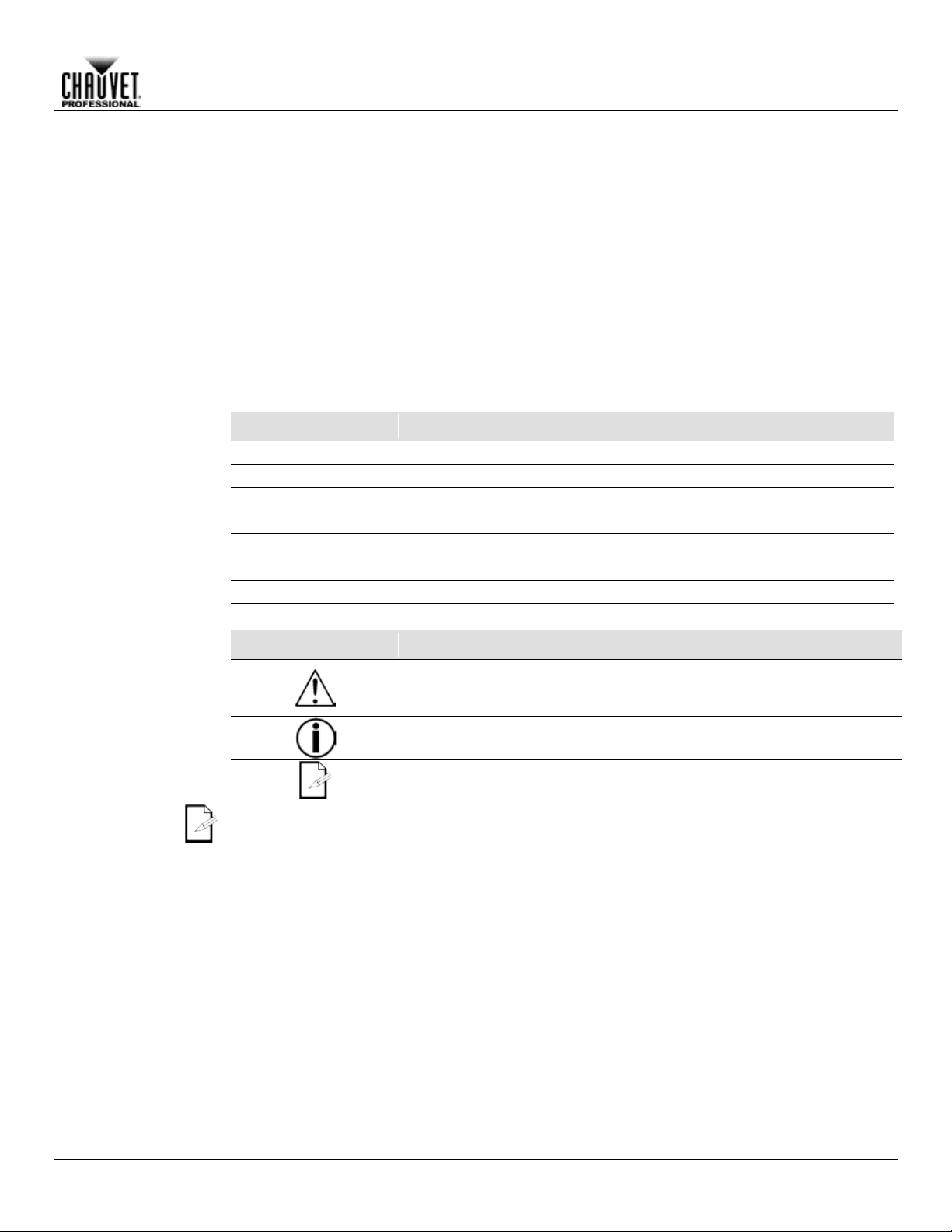
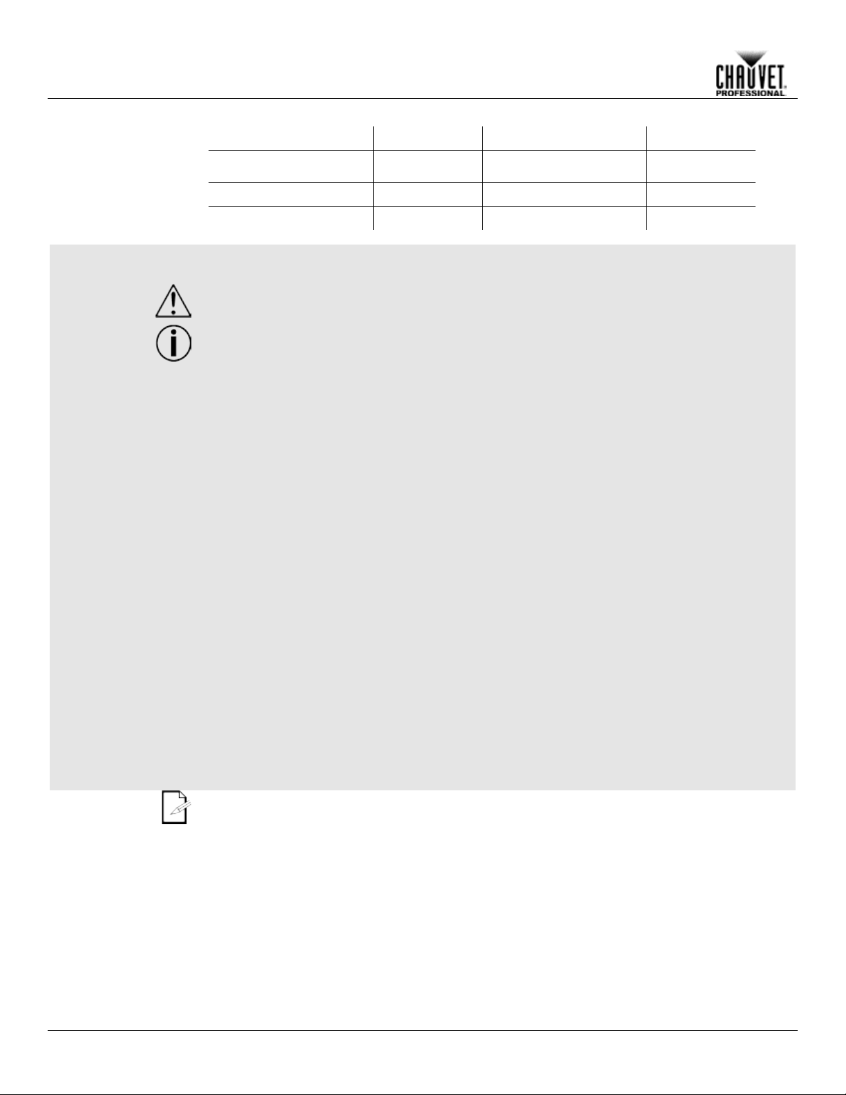
Symbols
Symbols
Meaning
Critical installation, configuration, or operation information. Failure to
damage third-party equipment, or cause harm to the operator.
with this information may keep the product from working.
The term “DMX” used throughout this manual refers to the USITT DMX512-A digital data
transmission protocol.
Before You Begin
Included
Conventions
• Neutrik powerCON power cord
• Warranty Card
the package and are in good condition.
shipping or show signs of mishandling, notify the carr ier immediately, not Chauvet
report damage to t
and contents for inspection.
Convention Meaning
comply with this information may cause the product not to work,
Important installation or configuration information. Failure to comply
Useful information.
STRIKE 4 User Manual Rev. 2 -1-
Page 6
Product At A
x
P
x
Auto-Ranging Power
Supply
P
P
P
P
x
Safety Notes
Read all the following Safety Notes before working with this product. These notes include
important information about the installation, usage, and maintenance of this product.
This product contains no user-serviceable parts. Any referen ce to s ervicing in this Us er
housing or attempt any repairs.
Personal Safety
• Avoid direct eye exposure to the light source while the product is on.
• Do not touch this product’s housing during operation because it may be very hot.
Mounting And
• This product is for indoor use only! To prevent risk of fire or shock, do not expose this
• When hanging this product, always secure to a fastening device using a safety cable.
Power And
• Always make sure you are connecting this product to the proper voltage in accordance with
• Never disconnect this product by pulling or tugging on the power cable.
Operation
• Do not operate this product if you see damage on the housing, lenses, or cables. Have the
In case of a serious operating problem, stop using this product immediately!
In the unlikely event that your Chauvet product may require service, contact Chauvet
Technical Support.
Expected LED
LEDs gradually decline in brightnes s over time, most ly because of heat. Packaged in clusters,
conditions. For this
projection intensity may also help to extend the LEDs’ lifespan.
Before You Begin
Use on Dimmer
Glance
Rigging
Outdoor Use
Master/Slave
DMX
Manual will only apply to properly trained Chauvet certified technicians. Do not open the
All applicable local codes and regulations apply to proper installation of this product.
• Always disconnect this product from its power source before servicing.
• Always connect this product to a grounded circuit to avoid the risk of electrocution.
product to rain or moisture. (IP20)
• CAUTION: When transferring product from extreme temperature environments, (e.g. cold
truck to warm humid ballroom) condensation may form on the internal electronics of the
product. To avoid causing a failure, allow product to fully acclimate to the surrounding
environment before connecting it to power.
• Mount this product in a location with adequate ventilation, at least 20 in (50 cm) from
adjacent surfaces.
• Make sure there are no flammable materials close to this product while it is operating.
Auto Programs
Replaceable Fuse
User-Serviceable
Wiring
Lifespan
-2- STRIKE 4 User Manual Rev. 2
the specifications in this manual or on the product’s specification label.
• To eliminate unnecessary wear and improve its lifespan, during periods of non-use
completely disconnect the product from power via breaker or by unplugging it.
• Never connect this product to a dimmer pack or rheostat.
damaged parts replaced by an authorized technician at once.
• Do not cover the ventilation slots when operating to avoid internal overheating.
• The maximum ambient temperature is 113 °F (45 °C). Do not operate this product at a
higher temperature.
•
LEDs exhibit higher operating temperatures than in ideal, single-LED
reason, using clustered LEDs at their fullest intens ity significantly reduc es the LEDs’ lifespan.
Under normal condit ions, this lifes pan can be 40,0 00 to 50, 000 ho urs . If ex tendin g this lif espan
is vital, lower the o perating temperature by impr oving the ventilation around th e product and
reducing the ambient temperature to an optim al oper a ting ra nge. I n addition, limiting the overall
Page 7

2. INTRODUCTION
Description
The STRIKE 4 features four independently focusable 100W chip-on-board LEDs that provide
incredible output and coverage for a wide gamut of production genres. STRIKE 4 features
tomated strobe
effects for using the STRIKE 4 as an au dience blinder, individual manual pan control of each
LED pod and adjustable PW M for using the STRIKE 4 in film and studio locations. STR IKE 4
s for flexibilit y in program m ing, and
an easy-to-read OLED display for quick onboard adjustments.
Features
• 1-, 3-, 4-, or 9-channel LED wash product
• Adjustable Pulse Width Modulation (PWM) control to eliminate flicker on camera
smooth 16-bit dimm ing control for those incand escent-style fades , a series of au
comes standard with basic and advanced c ontrol personalitie
• Operating modes:
• 1-channel: strobe
• 3-channel: intensity, duration, rate, effect, macro
• 4-channel: flash 1–8
• 9-channel: flash 1–8, auto programs, auto speed, dimmer, strobe
• 16-bit dimming control for smooth, perfect fades
• Individual pan of each head to allow for directional adjustment of light output
• Simple and complex DMX channel profiles for programming flexibility
• Easy to use OLED display
• Automated strobing programs for easy programming
Introduction
STRIKE 4 User Manual Rev. 2 -3-
Page 8

Front View
Rear View
Side View
Top View
Introduction
Overview
Mounting Bracket 1
DMX
In/Out
Fuse
Mounting Bracket 2
Safety Eye Bolt
Control
Panel
Power
In/Out
-4- STRIKE 4 User Manual Rev. 2
Page 9

Dimensions
8.27 in
210 mm
14.25 in
362 mm
14.25 in
362 mm
5.98 in
152 mm
6.42 in
163 mm
Introduction
2.95 in
75 mm
STRIKE 4 User Manual Rev. 2 -5-
Page 10

AC Power
Each STRIKE 4 has an auto-ranging power supply that works with an input voltage range of 100
, refer to the
chart in this
The listed current r ati ng in d icat es t he maximum curr ent dr a w duri ng nor mal operation. For more
:
www.chauvetprofessional.com.
• Always connect this product to a protected circuit with an appropriate electrical
completely disconnect the product from power via breaker or by unplugging it.
Never connect this product to a rheostat (variable resistor) or dimmer circuit, even if the
rheostat or dimmer channel serves only as a 0 to 100% switch.
AC Plug
The STRIKE 4 comes with a power input cord terminated with a Neutrik powerCO N A connector
on one end and an Edison plug on the other end (U.S. market). If the power input cord that
came with your produc t has no plug, or if you nee d to change the Edison plug, us e the table
below to wire the new plug.
AC Live
Black
Brown
Yellow or Brass
AC Neutral
White
Blue
Silver
AC Ground
Green/Yellow
Green/Yellow
Green
Power Linking
The STRIKE 4 supports power linking. You can power link up to 5 products at
for purchase.
Fuse
1. Disconnect this product from the power outlet.
4. Screw the fuse holder cap back in place and reconnect power.
Make sure to disconnect the product’s power cord before replacing a blown fuse. Always
replace the blown fuse with another of the sa me type an d ra ting.
Setup
3. SETUP
to 240 VAC, 5 0/60 Hz. To determine th e power requirem ents for each STRIKE 4
label affixed to the product. You can also refer to the Technical Specifications
manual.
information, you may download Sizing Circuit Breakers from the Chauvet website
ground to avoid the risk of electrocution or fire.
• To eliminate unnecessary wear and improve its lifespan, during periods of non-use
120 V; up to 9 at 208 V; or up to 10 at 230 V.
This product com es with a power input cord. Power link ing cables are available fr om Chauvet
Replacement
2. Using a Phillips-head screwdriver, unscrew the fuse holder cap from the housing.
3. Remove the blown fuse and replace with another fuse of the same type and rating
(T 5 A, 250 V).
Connection Wire (U.S.) Wire (Europe) Screw Color
-6- STRIKE 4 User Manual Rev. 2
Page 11

DMX Linking
You can link the ST RIKE 4 to a DMX control ler using a 5-pin DMX connecti on. If using other
DMX-compatible products with the STRIKE 4, yo u can control eac
h individually with a single
DMX controller.
DMX
The STRIKE 4 uses a 5-pin DMX data connection for the 1-, 3-, 4- and 9-channel DMX
personalities.
If you are not familiar with or need more information about DMX standards, Master/Slave
connectivity, or the DMX cables needed to link this product to a DMX controller,
download the DMX Primer from the Chauvet website: www.chauvetprofessional.com.
Master/Slave
The Master/Slave m ode allo ws a single ST RIKE 4 (the “master”) to c ontrol the a ctions of one or
(the “slaves”) without the need of a DMX controller to control the
slaves. Once set and connected, the slaves will operate in unison with the master. For
instructions on connecting and configuring this product, see Master/Slave Mode.
DO NOT connect a DMX controller to products operating in Master/Slave mode. The DMX
controller signals may interfere with the signals from the master.
If you are not familiar with or need more information about DMX standards, or the DMX
cables needed to link this product to a DMX controller, download the DMX Primer from
the Chauvet website: www.chauvetprofessional.com.
Setup
Personalities
personalities.
• Refer to the Introduction chapter for a brief description of each DMX personality.
• Refer to the Operation chapter to learn how to configure the STRIKE 4 to work in these
personalities.
• The DMX Values secti on prov ides you with detailed information regarding the DMX
Connectivity
more STRIKE 4 products
STRIKE 4 User Manual Rev. 2 -7-
Page 12

Mounting
Before mounting this product, read and follow the Safety Notes. For our CHAUVET
Professional line of mounting clamps, go to http://trusst.com/products/.
Orientation
Always mount this product in a safe position and make sure there is adequate room for
Rigging
Chauvet recommends using the following general guidelines when mounting this product.
• When selecting an installation location, consider easy access to this product for operation,
our CHAUVET Professional line of safety cables, go to http://trusst.com/products/.
Procedure
The STRIKE 4 comes with a 2 position yoke that allows you to attach mounting clamps for
are capable of
For our
CHAUVET Professional line of mounting clamps, go to http://trusst.com/products/.
Overhead Mounting
Setup
ventilation, configuration, and maintenance.
programming adjustments, and routine maintenance.
• Make sure to mount this product away from any flammable material as indicated in the
Safety Notes
.
• Never mount in places where rain, high humidity, extreme temperature changes, or
restricted ventilation may affect the product.
• If hanging this product, make sure that the mounting location can support the product’s
weight. See the T echnic al Specif icat io ns
for the weight-bearing requirements of this
product.
• When hanging this product, always secure to a fastening device using a safety cable. For
hanging. You must s upply your own mounting clamps. Mak e sure the clamps
supporting the weight of this product. Use at least one mounting point per product.
Mounting Diagram
Mounting Clamp
Safety Cable
-8- STRIKE 4 User Manual Rev. 2
Page 13

4. OPERATION
Control Panel
Button
Function
<MENU>
Exits from the current menu or function
<ENTER>
Enables the currently displayed menu or sets the currently selected
value in to the current function
<UP>
Navigates upward through the menu list or increases the numeric
value when in a function
<DOWN>
Navigates downward through the menu list or decreases the numeric
value when in a function
Control Options
You can set the ST RIKE 4 starting address in the 001–512 DMX r ange. This enables c ontrol of
up to 56 products in the 9-channel personal ity.
Programming
Refer to the Menu Map to under stand the menu options . The menu map shows the m ain level
• Press <MENU> repeatedly to exit to the previous main level.
DMX
Personality
This setting allows you to choose a particular DMX personality.
2. Select the desired personality (1 Ch, 3 Ch, 4 Ch, or 9 Ch).
• See the DMX Values section for the highest starting address you can select for each
the new personality setting.
DMX Control
In this mode, each product will r espond to a unique s tarting addr ess fr om the DMX contr oller. All
3. Select the starting address (001–512).
The highest recommended starting address for each DMX mode is as follows:
1 Ch
512
3 Ch
510
4 Ch
509
9 Ch
504
Description
and a variable number of programming levels for each option.
• To go to the desired main level, press <MENU> repeatedly until the option shows on the
• To select an option or value within the current programming level, press <UP> or <DOWN>
Operation
display. Press <ENTER> to select. This will take you to the first programming level for that
option.
until the option shows on the display. Press <ENTER> to select. In this case, if there is
another programming level, you will see that first option, or you will see the selected value.
1. Go to the DMX Channel main le ve l.
personality.
• Make sure that the starting addresses on the various products do not overlap due to
products with the same starting address will respond in unison.
1. Select a DMX personality as shown in DMX Personality.
2. Go to the DMX Address main level.
DMX Mode DMX Address
STRIKE 4 User Manual Rev. 2 -9-
Page 14

Static Operation
The Static mode allows the user to set t he intensity and the strobe frequency from the
5. Select the desired strobe frequency (000–255).
Auto Programs
Auto programs allow for control of pre-programmed strobe looks without a DMX controller.
4. Choose the desired speed value (000–100).
Auto Test
This option allows you to test all the LEDs on the STRIKE 4.
2. Select Auto > Test.
Master/Slave
The Master/Slave mode allows a group of STRIKE 4s (the slaves) to simultaneously
explained in Static Operation.
• The master is the one that runs a program whether in Auto Show or Static
• The master should be the first product in the daisy chain.
Software
Information
This option shows what version of software the STRIKE 4 is running.
2. Select Version and the version number will show on the screen.
Temperature
This option shows the internal temperature of each of the STRIKE 4’s individual pods.
2. Select LED 1–4
Backlight
This setting allows you to set the am ount of time the bac klight on the STRI KE 4 stays on
3. Press <ENTER>.
Operation
control panel without a DMX controller.
1. Go to the Static main level.
2. Select Dimmer.
3. Choose desired intensity (000–255).
4. Select Strobe.
1. Go to the Auto Show main level.
2. Select the desired auto program (Auto 0–6).
3. Select Speed.
You cannot edit any of the auto programs (A u to 0–6).
1. Go to Information main level.
duplicate the output of another STRIKE 4 (the master) without a DMX controller.
1. Set each of the slaves:
a. Go to the Master/Slave Mode main level.
b. Select Slave.
2. Set the master product:
a. Go to the Master/Slave Mode main level.
b. Select Master.
c. Select an Auto program as explained in Auto Programs
or Static program as
mode.
• Do not connect a DMX controller to the products configured for Master/Slave
operation. The DMX controller may interfere with signals from the master
product.
1. Go to the Information main level.
1. Go to the Temperature main level.
after the last button is pressed on the control panel.
1. Go to the Back Light main level.
2. Select On (remains on), 10 S (10 seconds), 20 S (20 seconds), or 30 S (30 seconds).
-10- STRIKE 4 User Manual Rev. 2
Page 15

Dimmer Curves
The STRIKE 4 provides four different options to simulate the dimming curve of an
2. Select a dimmer curve (Off, Dimmer 1, Dimmer 2, or Dimmer 3).
OFF:
The output is proportional (linear) to the Dimmer chann el values .
DIM1~3:
The output follows the Dimmer channel values based on the corresponding
dimmer curve, being Dimmer 1 the fastest and Dimmer 3 the slowest.
Fixture Hours
This option shows the total amount of hours the STRIKE 4 has been turned on.
2. Select Fixture Hours. (the hours will show on the screen)
LED Frequency
This option changes the Pulse Width Modulation (PWM) frequency of the LEDs on the
2. Select PWM Frequency (600 Hz, 1200 Hz, 2000 Hz, 4000 Hz, or 25Khz).
Fan Control
The STRIKE 4 allows you to adjust the fan speed of the product to allow for quiet
2. Select Auto or High.
Operation
incandescent lighting product.
1. Go to the Dimmer Mode main level.
1. Go to the Information main level.
STRIKE 4.
1. Go to the LED Frequency main level.
operation.
1. Go to the Fan Mode main level.
STRIKE 4 User Manual Rev. 2 -11-
Page 16

Auto Show
Auto 1–6
Speed
0–100
Automatic programs
Dimmer
Sets the intensity of the light output
Strobe
Selects the strobe frequency
Off
No dimmer
Dimming curves Dimmer 1 (fast) to
Dimmer 3 (slow)
Turns off display backlight after 10 sec of
inactivity
Turns off display backlight after 20 sec of
inactivity
Turns off display backlight after 30 sec of
inactivity
On
Display backlight alwa ys on
Auto
Test
Turns on all LEDs in sequence for testing
Fixture Hours
Shows total product hours
Version
Shows installed software vers ion
Selects DMX address (highest channel
restricted to personality chosen)
1 Ch
1-channel: dimmer
3 Ch
3-channel: dimmer H, dimmer L, Strobe
4 Ch
4-channel: pod 1–4
9-channel: pod 1–4, auto programs, dimmer
speed, dimmer H, dimmer L, strobe
Master
Master mode
Slave
DMX mode (Slave mode)
Auto
High
LED1
LED2
LED3
LED4
600Hz
1200 Hz
2000 Hz
4000 Hz
25KHz
Operation
Menu Map
Main Level Programming Levels Description
Static
Dimmer Mode
Dimmer 1–3
10S
Back Light
20S
30S
Information
DMX Address 001–512
DMX Channel
9 Ch
0-255
Master/Slave Mode
Fan Mode
Temperature
LED Frequency
-12- STRIKE 4 User Manual Rev. 2
Fan control
Individual pod temperature
PWM frequency
Page 17

DMX Values
9 Ch
1
Dimmer H
000ó255
0–100%
2
Dimmer L
000ó255
0–100%
000ó010
133ó255
No function
0–20 Hz (Random strobe macros)
4
White 1
000ó255
0–100%
5
White 2
000ó255
0–100%
6
White 3
000ó255
0–100%
7
White 4
000ó255
0–100%
000ó010
241ó255
No function
No function
000ó010
121ó255
Preset dimmer speed from display menu
Preset dimmer speed from display menu
1 Ch
1
Dimmer H
000ó255
0–100%
3 Ch
Channel
Function
Value
Percent/Setting
1
Dimmer H
000ó255
0–100%
2
Dimmer L
000ó255
0–100%
000ó010
133ó255
No function
0–20 Hz (Random strobe macros)
4 Ch
1
White 1
000ó255
0–100%
2
White 2
000ó255
0–100%
3
White 3
000ó255
0–100%
4
White 4
000ó255
0–100%
Operation
Channel Function Value Percent/Setting
3 Strobe
8 Auto Programs
9 Dimmer Speed
Channel Function Value Percent/Setting
011ó132
011ó040
041ó080
081ó120
121ó160
161ó200
201ó240
011ó040
041ó080
081ó120
0–20 Hz (All pods)
Auto 1
Auto 2
Auto 3
Auto 4
Auto 5
Auto 6
Nonlinear dimming curve 1 (fastest)
Nonlinear dimming curve 2
Nonlinear dimming curve 3 (slowest)
3 Strobe
Channel Function Value Percent/Setting
STRIKE 4 User Manual Rev. 2 -13-
011ó132
0–20 Hz (All pods)
Page 18

Operation
STRIKE 4 Pod Selection for DMX Control
1
3
2
4
STRIKE 4 Angle Adjustment for DMX Control
-24° to 24°
Adjustment
-24° to 24°
Adjustment
-14- STRIKE 4 User Manual Rev. 2
Page 19

5. TECHNICAL INFORMATION
Product
To maintain optim um performance and minimize wear, you sho uld c le an this product fr equent l y.
light output
performance and can cause overheating. This can lead to reduced light source life and
7. Gently polish the lens surfaces until they are free of haze and lint.
Technical Information
Maintenance
Usage and environment are contributing factors in determining the cleaning frequency.
As a rule, clean this product at least twice a month. Dust build-up reduces
increased mechanical wear.
To clean your product:
1. Unplug the product from power.
2. Wait until the product is at room temperature.
3. Use a vacuum (or dry compressed air) and a soft brush to remove dust collected on the
external vents.
4. Clean all external surfaces with a mild solution of non-ammonia glass cleaner or isopropyl
alcohol.
5. Apply the solution directly to a soft, lint-free cotton cloth or a lens cleaning tissue.
6. Wipe any dirt or grime to the outside edges of the lens surface.
Always dry the external surfaces thoroughly and carefully after cleaning them.
Do not spin the cooling fans while blowing compressed air into them.
STRIKE 4 User Manual Rev. 2 -15-
Page 20

Dimensions and
14.2 in (362 mm)
6.4 in (163 mm)
14.2 in (362 mm)
19 lb (8.7 kg)
Note: Dimensions in inches rounded to the nearest decimal digit.
Power
Switching (internal)
100–240 VAC, 50/60 Hz
Auto-ranging
Consumption
301 W
286 W
Current
2.49 A
1.29 A
Power linking current
(products)
13.6 A (5 products)
13.6 A (10 products)
Fuse/Breaker
T 5 A, 250 V
T 5 A, 250 V
Power I/O
U.S./Canada
Worldwide
Power input connector
Neutrik powerCON A
Neutrik powerCON A
Power output connector
Neutrik powerCON B
Neutrik powerCON B
Power cord plug
Edison (U.S.)
Local plug
Light Source
LED
100 W
50,000 hours
White
4
2.3 A
Photometrics
Parameter
Total
Per Cell
Illuminance @ 5 m
999 lux
242 lux
Beam angle
49°
Field angle
79°
Thermal
113 °F (45 °C)
Fan-Assisted Convection
DMX
5-pin XLR
Sockets
1, 3, 4 or 9
Ordering
STRIKE 4
03051079
781462214272
Technical Specifications
6. TECHNICAL SPECIFICATIONS
Weight
Length Width Height Weight
Power Supply Type Range Voltage Selection
Parameter 120 VAC, 60 Hz 230 VAC, 50 Hz
Type Power Lifespan
Color Quantity Current
Max. External Temperature Cooling System
I/O Connectors Connector Type Channel Range
Product Name Item Code UPC Number
-16- STRIKE 4 User Manual Rev. 2
Page 21

Photometrics
Chart
Technical Specifications
STRIKE 4 User Manual Rev. 2 -17-
Page 22

Returns
You must send the product prepaid, in the original box, and with the original packing and
and request a Return Merc handise Authorization (RMA) num ber before shipping
the product. Be prepared to provide t he m odel num ber, s erial num ber, and a br ief des cripti on of
will refuse any product returned
without an RMA number.
DO NOT write the RMA number directly on the box. Instead, write it on a properly affixed
label.
Once you have rec ei ved the RMA num ber, include the follo win g inf or mation on a piece of pa per
Be sure to pack the product properly. Any shipping damage resulting from inadequate
recommended.
Chauvet reserves the right to use its own discretion to repair or replace returned
product(s).
Technical Specifications
accessories. Chauvet will not issue call tags.
Call Chauvet
the cause(s) for the return.
Clearly label the package with an RMA number. Chauvet
inside the box:
• Your name
• Your address
• Your phone number
• The RMA number
• A brief description of the problem(s)
packaging will be the customer’s responsibility. FedEx packing or double-boxing is
-18- STRIKE 4 User Manual Rev. 2
Page 23

C
USA WORLD HEADQUARTERS
General Information – Chauvet
Technical Support
EUROPE
General Information - Chauvet Europe BVBA
Technical Support
General Information - Chauvet Europe Ltd.
Technical Support
MEXICO
General Information - Chauvet Mexico
Voice: +52 (728) 285-5000
Technical Support
Outside the U.S., United Kingdom, Ireland, Mexico, or Benelux contact the dealer of record.
details.
ONTACT
US
Address: 5200 NW 108th Avenue
Sunrise, FL 33351
Voice: (954) 577-4455
Fax: (954) 929-5560
Toll free: (800) 762-1084
User Manual
Voice: (954) 577-4455 (Press 4)
Fax: (954) 756-8015
Email: tech@chauvetlighting.com
World Wide Web www.chauvetlighting.com
Address: Stokstraat 18
9770 Kruishoutem
Belgium
Email: Eutech@chauvetlighting.eu
World Wide Web www.chauvetlighting.eu
Voice: +32 9 388 93 97
Address: Unit 1C
Brookhill Road Industrial Estate
Pinxton, Nottingham, UK
Email: uktech@chauvetlighting.com
World Wide Web www.chauvetlighting.co.uk
NG16 6NT
Voice: +44 (0)1773 511115
Fax: +44 (0)1773 511110
Address: Av. Santa Ana 30
Parque Industrial Lerma
Lerma, Mexico C.P. 52000
Email: servicio@chauvet.com.mx
World Wide Web www.chauvet.com.mx
Follow their instructi ons to request support or to ret urn a product. Visit our website for contact
STRIKE 4 User Manual Rev. 2
 Loading...