

Page 1
User Manual
Page 2

Edition Notes
Edition
Notes
The RDM2go User Manual Rev. 1 includes a descr iption, safety precautions, and installati on,
as of the release date
Other company and product names and logos referred to herein may be trademarks of their
respective companies.
Copyright Notice
The works of authors hip contained in this manual, includi ng, but not limited to, all design, t ext
Manual Use
Chauvet authorizes it s c us tomers to download and pr i nt th is manual for profess ional infor mation
sage, copy, stora ge, distributio n, modification,
ts content for any other purpose without written consent from
Chauvet.
Document
Printing
For better results, pr int this docum ent in c olor, on lett er size pap er ( 8.5 x 1 1 in), d ouble-sided. If
Intended
Any person in charge of ins talling, operatin g, and/or maintaining th is product should completely
before installing,
operating, or maintaining this product.
Disclaimer
Chauvet believes that the information contained in this manual is accurate in all respects.
age or disruption caused by any errors or omissions in this
document, whether such errors or omissions result from negligence, accident or any other
and does not commit to make, any such revisions..
Document
Revision
The RDM2go User Manual Rev. 1 is the first edition of this manual. Go to
Trademarks
programming, operation, a nd maintenance instructions for the RDM2go
of this edition in November 2015.
CHAUVET, the Chauvet logo and RDM2go are registered trademarks or trademarks of Chauvet
& Sons LLC. (d/b/a Chauvet and Chauvet Lighting) in the United States and other countries.
and images are owned by Chauvet.
© Copyright 2015 Chauvet & Sons, LLC. All rights reserved.
Electronically published by Chauvet in the United States of America.
purposes only. Chauv et expressly proh ibits the u
or printing of this manual or i
using A4 paper (210 x 297 mm), configure your printer to scale the content accordingly.
Audience
read through the guide that shipped with the product, as well as this manual,
However, Chauvet assum es no responsibility and specifically discla ims any and all liability to
any party for any loss, dam
cause. Chauvet res erves the ri ght to re vise the c ontent of this docum ent without an y obligatio n
to notify any pers on or c ompany of such r e visi on, ho wever , Ch au vet has no obligation to make,
www.chauvetprofessional.com for the latest version.
RDM2go User Manual Rev. 1
Page 3

Table of Contents
Table of Contents
1. Before You Begin ...................................................................................................................................... 1
What Is Included ........................................................................................................................................................... 1
Claims .......................................................................................................................................................................................... 1
Manual Conventions .................................................................................................................................................................... 1
Symbols ....................................................................................................................................................................................... 1
Safety Notes ................................................................................................................................................................. 2
Personal Safety ............................................................................................................................................................................ 2
Mounting And Rigging .................................................................................................................................................................. 2
Power And Wiring ........................................................................................................................................................................ 2
Operation ..................................................................................................................................................................................... 2
2. Introduction ............................................................................................................................................... 3
Description .................................................................................................................................................................... 3
Features ........................................................................................................................................................................ 3
Overview ....................................................................................................................................................................... 4
Dimensions ................................................................................................................................................................... 5
3. Setup .......................................................................................................................................................... 6
DC Power...................................................................................................................................................................... 6
Charging the Battery .................................................................................................................................................................... 6
Battery Charge Notes ................................................................................................................................................................... 6
Storage Notes .............................................................................................................................................................................. 6
Connection .................................................................................................................................................................... 7
Remote Device Management (RDM) ........................................................................................................................... 7
Ilumicode....................................................................................................................................................................... 7
4. Operation ................................................................................................................................................... 8
Control Panel Description ............................................................................................................................................. 8
Programming ................................................................................................................................................................ 8
Menu Map ..................................................................................................................................................................... 9
Menu Map (Cont.) ....................................................................................................................................................... 10
Menu Map (Cont.) ....................................................................................................................................................... 11
Cable Test Chart ......................................................................................................................................................... 11
RDM ............................................................................................................................................................................ 12
Ilumicode..................................................................................................................................................................... 12
DMX Starting Address ................................................................................................................................................................ 12
DMX Personality ........................................................................................................................................................................ 12
DMX Values ............................................................................................................................................................................... 13
Static Colors ............................................................................................................................................................................... 13
Dimmer ...................................................................................................................................................................................... 13
Color .......................................................................................................................................................................................... 13
(Full Color Products) .................................................................................................................................................................. 13
Whites Setting ............................................................................................................................................................................ 13
Reset to Factory Settings ........................................................................................................................................................... 13
Send DMX................................................................................................................................................................... 14
Channel Adjustment ................................................................................................................................................................... 14
Send Options ............................................................................................................................................................................. 14
Receive DMX .............................................................................................................................................................. 15
View incoming DMX Values ....................................................................................................................................................... 15
Cable Test................................................................................................................................................................... 15
Using the Cable Tester .............................................................................................................................................................. 15
Power Options ............................................................................................................................................................ 15
Using the Power Options ........................................................................................................................................................... 15
Information .................................................................................................................................................................. 15
RDM2go User Manual Rev. 1 -i-
Page 4

Table of Contents
5. Technical Information ............................................................................................................................. 16
Product Maintenance .................................................................................................................................................. 16
6. Technical Specifications ......................................................................................................................... 17
Returns ....................................................................................................................................................................... 18
Contact Us ................................................................................................................................................... 19
-ii- RDM2go User Manual Rev. 1
Page 5
1. Before You Begin
What Is
• RDM2go
• Quick Reference Guide
Claims
Carefully unpack the pr oduct immediately and check the box to make sure all the parts are in
If the box or the contents (the product and included accessories) appear damaged from
. Failure to
tion, keep the box
For other issues, such as missing components or parts, damage not related to shipping, or
concealed damage, file a claim with Chauvet within 7 days of delivery.
Manual
Convention
Meaning
1–512
A range of values in the text
50/60
A set of mutually exclusive values in the text
<SET>
A button on the product’s control panel
Settings
A product function or a menu option
Mode>Settings
A sequence of menu options
1–10
A range of menu values from which to choose in a menu
Yes/No
A set of two mutually exclusive menu options in a menu
ON
A unique value to be entered or selected in a menu
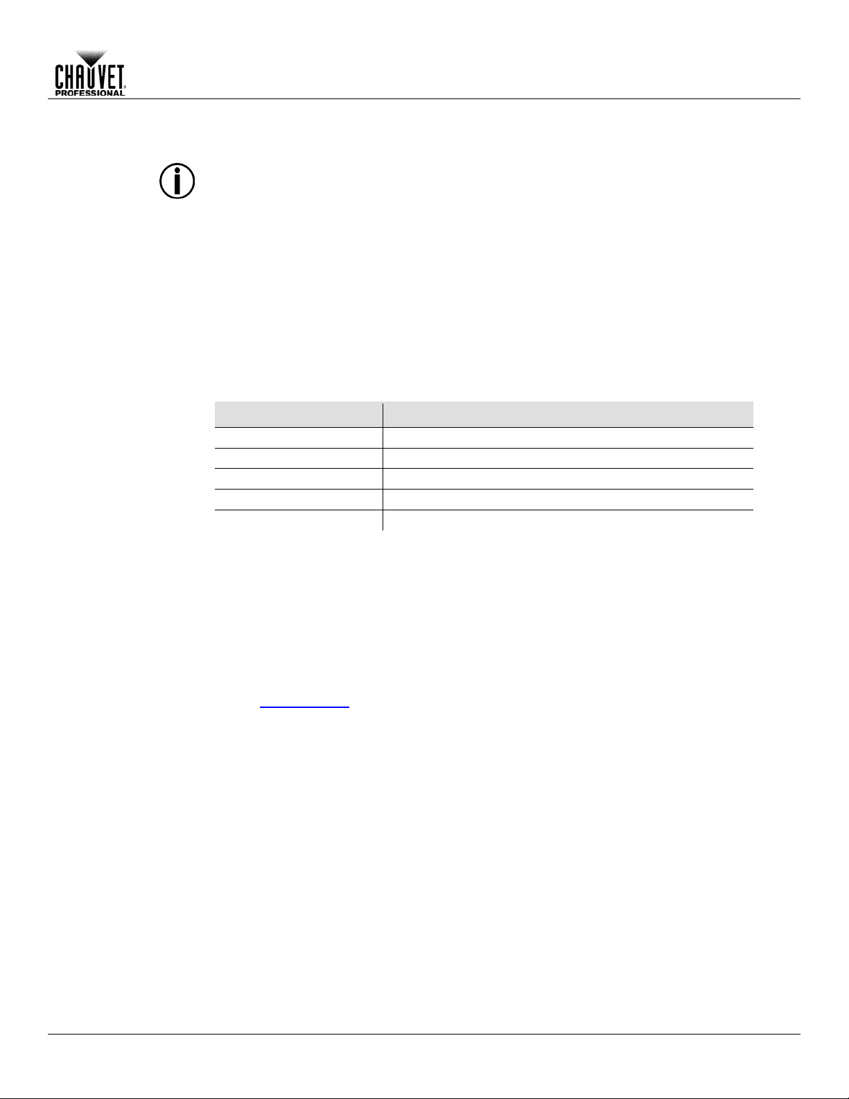
Symbols
Critical installation, configuration, or operation information. Failure to
damage third-party equipment, or cause harm to the operator.
Important installation or configuration information. Failure to comply
The term “DMX” used throughout this manual refers to the USITT DMX512-A digital data
transmission protocol.
Before You Begin
Included
Conventions
• Carry Pouch
• 2 pc, 3- to 5-pin converters
• 5-pin male to bare wire adaptor
• USB-A Male to Micro USB-B Male (3 ft)
• Warranty Card
the package and are in good condition.
shipping or show signs of m ishandling, notify the carrier immediately, not Chauvet
report damage to the c arrier immediately may inval idate your claim. In addi
and contents for inspection.
Symbols Meaning
comply with this information may cause the product not to work,
with this information may keep the product from working.
Useful information.
RDM2go User Manual Rev. 1 -1-
Page 6
Safety Notes
Read all the following Safety Notes before working with this product. These notes include
important information about the installation, usage, and maintenance of this product.
This product contains no user-serviceable parts. Any referen ce to s ervicing in this Us er
housing or attempt any repairs.
Personal Safety
• Always disconnect this product from its power source before servicing.
• Always connect this product to a grounded circuit to avoid the risk of electrocution.
Mounting And
• The product is not intended for permanent installation.
• Make sure there are no flammable materials close to this product while it is operating.
Power And
• Always make sure you are connecting this product to the proper voltage in accordance with
• Never disconnect this product by pulling or tugging on the power cable.
Operation
• Do not operate this product if you see damage on the housing, lenses, or cables. Have the
• In case of a serious operating problem, stop using this product immediately!
In the unlikely event that your Chauvet product requires service, contact Chauvet
Technical Support.
Before You Begin
Manual will only apply to properly trained Chauvet certified technicians. Do not open the
All applicable local codes and regulations apply to proper installation of this product.
Rigging
Wiring
• This product is for indoor use only! To prevent risk of fire or shock, do not expose this
product to rain or moisture. (IP20)
• CAUTION: When transferring product from extreme temperature environments, (e.g. cold
truck to warm humid ballroom) condensation may form on the internal electronics of the
product. To avoid causing a failure, allow product to fully acclimate to the surrounding
environment before connecting it to power.
the specifications in this manual or on the product’s specification label.
• To eliminate unnecessary wear and improve its lifespan, during periods of non-use
completely disconnect the product from power via breaker or by unplugging it.
• Never connect this product to a dimmer pack or rheostat.
damaged parts replaced by an authorized technician at once.
• Do not cover the ventilation slots when operating to avoid internal overheating.
• The maximum ambient temperature is 113 °F (45 °C). Do not operate this product at a
higher temperature.
-2- RDM2go User Manual Rev. 1
Page 7

2. Introduction
Description
The RDM2go is a multi-f unctional tool for working wit h lighting products over a DMX/RDM data
sized controller per forms a multitude of tas ks including RDM functional ity, DMX
a built in DMX ca ble integrity checker, and
easily recharges via a stand ard micro USB jack
and comes with a convenient carry pouch and connector convertors.
Features
• Control Protocol: DMX, RDM, Ilumicode
• Comes with connector adaptors, USB charging cord and belt clip pouch
line. The palm snapshot, test-scene record/playback, Ilumicode addressing for Iluminarc fixtures, and DMX
input/output monitor ing. The RDM2go also f eatures
an easy to read OLED displa y. The RDM2go
• DMX Channels: 1, 2, 3, 4, 5, 6 or 7
• Modes/Personalities (Ilumicode): 13 personalities (ARC 1, ARC 1+D, ARC2, ARC2+D,
ARC3, ARC3+D, ARC FULL, REMOTE, SOLID, SPECIAL1, SPECIAL2, VW, VW+D)
• Handheld tool for managing products and systems with DMX, RDM, and Ilumicode based
control
• Easily address, locate and monitor RDM capable fixtures
• Check DMX addressing, cabling, and store/playback basic snapshots
• Address and set personalities of Ilumicode based architectural fixtures
• Easy to read, large OLED display and easy to navigate menus
Introduction
RDM2go User Manual Rev. 1 -3-
Page 8
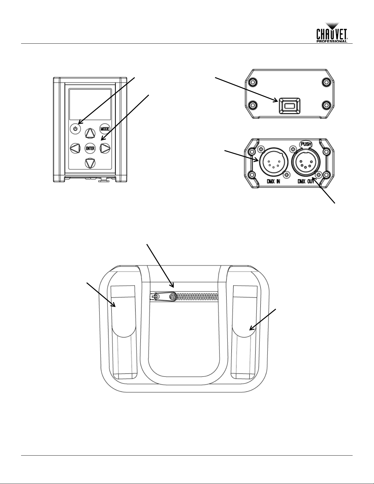
Top View
Front View
Carry Pouch
DMX In
DMX Out
Micro USB Input
Power On
Control Panel
3-to 5-pin
Cable Storage
5-to 3-pin
Adaptor
Bottom View
Introduction
Overview
DMX
DMX
Adaptor
-4- RDM2go User Manual Rev. 1
Page 9

Dimensions
6.46 in
2.76 in
3.93 in
4.80 in
1.53 in
100 mm
122 mm
70 mm
Introduction
164 mm
39 mm
RDM2go User Manual Rev. 1 -5-
Page 10

DC Power
This product operates on a rechargeable lithium ion battery.
Charging the
To recharge the product:
• To eliminate unnecessary wear and improve its lifespan, during periods of non-use
product to 50% and store in a cool dry environment.
Battery Charge
This product is equipped with a built-in rechar g eab le lit hium ion battery.
in storage. Routinely check the battery’s charge status
Storage Notes
• Store charged product(s) in a dry environment, away from direct sunlight.
• Store the battery at temperatures bet ween 41 °F and 68 °F (5 °C and 20 °C).
Micro USB Input
Setup
3. Setup
Battery
1. Plug the included cable into any USB-A female outlet.
2. Plug the Micro USB-B male end into the female socket located on top of the product.
completely disconnect the product from power by unplugging it.
• When storing product for long periods of time without charging or using, only charge
Notes
-6- RDM2go User Manual Rev. 1
• Recharge the battery within three days of last use.
• Avoid depleting the battery below 10%.
• Recharge/discharge the battery to 50% capacity before storing this product for extended
periods of time.
• For best results, charge the battery in a temperature between
32 ºF (0 ºC), and 95 ºF (35 ºC).
• When charging the battery, keep the product at least 1 m from any open flame or hot plate.
• Perform a full discharge/recharge cycle every three months.
• If the battery is completely discharged, the device cannot be turned on imm ediate l y when
the charger is connected. Allow a depleted battery to charge for a few minutes before
turning on the device.
• The device can be used while it is charging, but it may take longer to fully charge the
battery.
• While charging, the device may heat up. This is normal and should not affect the device’s
lifespan or performance. If the battery gets hotter than usual, the charger may stop
charging.
• Lithium-Ion batteries continue to slowly discharge (self-discharge) w hen not in use or while
• Charge or discharge t he ba ttery to approximately 50% of capacit y at least once every six
months.
• Charge or discharge the battery to approximately 50% of capacity before storage.
Page 11

Connection
You can link the RDM2go to other DMX contro lled products using a 5-pin DMX c onnection. If
, you can control each indivi dually with
a single DMX controller.
If you are not familiar with or need more information about DM X standards, Master/Slave
connectivity, or the DMX cables needed to link this product to a DMX controller,
download the DMX Primer from the Chauvet website: www.chauvetprofessional.com.
Remote Device
Management
Remote Device Management, or RDM, is a standard for allowing DMX-enabled devices to
ck the DMX controller’s User
Manual or with the manufacturer as not all DMX controllers have this capability. The
ws feedback to m ake changes to multip le attrib utes of
section in this Us er Manual for more detailed
examples explaining how to use this function.
Ilumicode
The RDM2go will work as an Ilum icode addresser using the 5-pin DMX serial connectio n located
at the bottom of the product and us ing the various adaptors inclu ded with this pr oduct and your
for more
information about connecting and configuring the product for Ilumicode operation.
Setup
using other DMX-com patible products with the RDM2go
communicate bi-directionally along existing DMX cabling. Che
(RDM)
RDM2go sup ports RDM protocol that allo
RDM-enabled products. Please r efer to the RDM
Iluminarc product. Download the Ilumicode User Manual from www.iluminarc.com
RDM2go User Manual Rev. 1 -7-
Page 12

Control Panel
Button
Function
Navigates downwards through the menu list or decreases the numeric
value when in a function
Programming
Refer to the Menu Map to under stand the menu options . The menu map shows the m ain level
• Press <MODE> repeatedly to exit to the previous level.
Operation
4. Operation
Description
Turns product On/Off
Scrolls through main level mode options and exits from the current menu or
function
Enables the currently displayed menu or sets the currently selected value
into the selected function
Navigates upwards through the menu list or increases the numeric value
when in a function
Navigates left through the menu list.
Navigates right through the menu list.
and a variable number of programming levels for each option.
• To go to the main menu level, press <MODE> repeatedly until the option shows on the
display. Press <ENTER> to select. This will take you to the first programming level for that
option.
• To select an option or value within the current programming level, press <UP> or <DOWN>
until the option shows on the display. Press <ENTER> to select. In this case, if there is
another programming level, you will see that first option, or you will see the selected value.
-8- RDM2go User Manual Rev. 1
Page 13
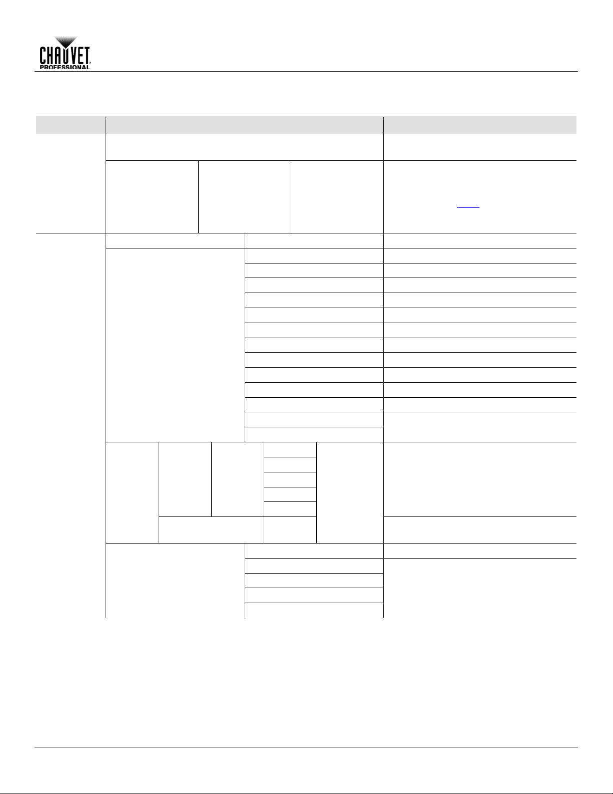
Menu Map
No RDM compatible products connected
to the RDM2go
* (choose from list
* (choose from the
Shows information about each product.
controllable
Start Address
001–512
Sets the DMX starting address
VW
2-channel: WW, CW control
VW+D
3-channel: WW, CW control + dimmer
ARC 1
3-channel: RGB control
ARC 1 + D
4-channel: RGB control + dimmer
ARC2
4-channel: RGBW(A) control
ARC2 + D
5-channel: RGBW(A) control + dimmer
ARC3
5-channel: RGBWA control
ARC3 + D
6-channel: RGBWA control + dimmer
ARC FULL
7-channel: RGB control + dimmer
REMOTE
Reserved for future use
SOLID
1-channel: Dimmer
SPECIAL 1
SPECIAL 2
RED
GREN
BLUE
COOL
WARM
Determines the white balance when
RGBTOW is active
OFF
Dimmer works in linear mode
DIM 1
DIM 2
DIM 3
DIM 4
Main Level Programming Levels Description
No Fixtures Found!
Operation
RDM
Ilumicode
Discovering...
PERSON
of products
connected)
attributes unique
to each product)
Some attributes will allow changes to be
made. See each individ ua l produc ts ’ User
Manual and the
RDM section of this
Manual to determine which attributes are
See each product’s User Manual
WHITE 01–11
CALIB
DIMMER
RDM2go User Manual Rev. 1 -9-
RGBTOW AMBE
000–255
Determines the white balance for the color
macros
Dimmer works in non-linear mode, from
fast to slow
Page 14

RED
GREN
BLUE
COOL
WARM
AMBE
SOLD
STRB
00–20
Configures strobe speed
OFF
Maximum output, unbalanc ed white
White output is as per CALIB >
RGBTOW settings
Output matches that of product’s
previous versions
RESET
NO/YES
Restores factory defaults
Normal
Adjust each channel individually
Adjust all channels together in
preconfigured increments.
Decimal
are displayed on the screen
Percent
Clear All Channels
Sets all channels to “0”
Up/
Speed
Left/
Fade
Uses Left/Right keys to adjust the
sequence
Enter: Play/Stop
Plays the DMX sequence
Step
100
Scene
032
Delete Sequence
No/Yes
Deletes/reset the DMX sequence
Store Scene
Scene
1–32
Records current DMX values
Load Scene
Loads a previously recorded scene
Operation
Menu Map (Cont.)
Main Level Programming Levels Description
Ilumicode
(Cont.)
Send DMX
STATIC
SETTINGS
T001
–
T512
000–
255
(000
–
100)
COLOR
Edit Mode
Show Level As
Dmx
Sequence
Play
Sequence
000–255
RGBTOW
All
Down:
Right:
Configures the static color
UC
Determines how the dimmer levels
Uses Up/Down keys to adjust the
Speed of the sequence
0.1”–60.0”
Fade Time of each step in the
-10- RDM2go User Manual Rev. 1
Edit
Sequence
001
–
End Of
Sequence –
Set-up and edit the DMX sequence
Page 15
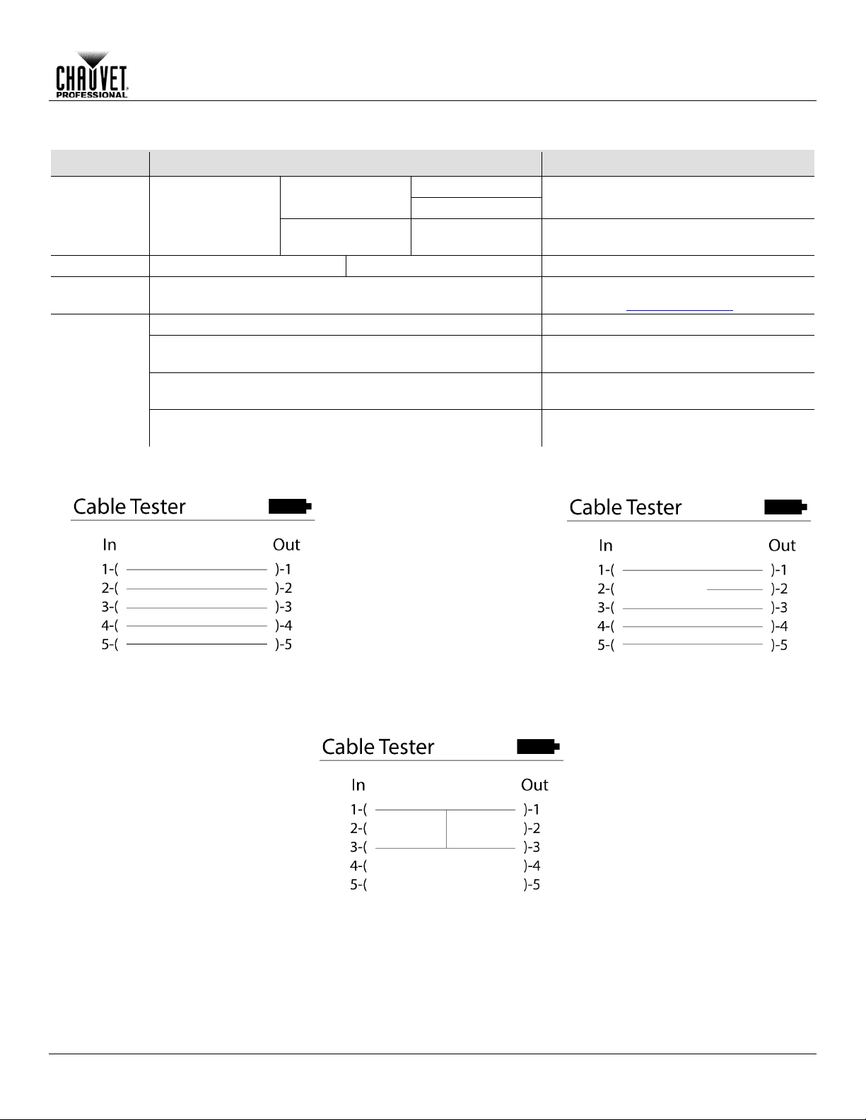
Menu Map (Cont.)
Decimal
displayed on the screen
Percent
Records the current DMX values as a
scene
Load Scene
Playing Scene 1–32
Scene 1–32
Loads a previously recorded scene
Tests the cable for any breaks or shorts in
the line. See Cable Test Chart
Off
Power saver feature is turned off
1 Minute
Product is powered off after 1 min of
inactivity
5 Minute
Product is powered off after 5 min of
inactivity
10 Minute
Product is powered off after 10 min of
inactivity
Good
Bad Pin 2
Pin 1 Shorted to Pin 3
Main Level Programming Levels Description
Operation
Show Level As
Receive DMX
R001–R512
Store Scene Scene 1–32
Cable Test In –––––– –––––– Out
Power
Options
Cable Test Chart
Determines how the dimmer levels are
RDM2go User Manual Rev. 1 -11-
Page 16

RDM
The RDM2go uses R emote De vice Manag ement ( RDM) sof tware that allows f eedback to m ake
4. Select and adjust each of the available of attributes.
RDM Product
Attributes
Below are some examples of more common attributes that will be listed on the LCD after
ma y or
For more information about RDM protocol and associated attributes, go to
www.openlighting.org.
Ilumicode
This Main Level selection contains all the parameters for all the compatible ILUMINARC
onsult the corresponding product’s user m anual to determine which
parameters on the Ilumicode V 2.21 apply to that specific product.
DMX Starting
Address
1. Go to Iumicode > Start Address.
“SEND…”
DMX Personality
1. Go to Iumicode > PERSON and select any DMX personality.
avoid address overlapping.
Operation
changes to connected RDM compatible products.
1. Go to the RDM main level.
2. The RDM2go will scan for RDM compatible products, Discovering... will display on the
screen.
a. No Fixtures Found – No RDM compatible products were found. Be sure your
connected products are RDM compatible check all connections and try again.
3. Select from the list of RDM compatible products displayed.
choosing from the lis t of available RDM compatibl e products. Each of these attributes
may not be changeable depending on each type of individual product.
• Label: Allows user input such as identity inform ation to be stored on the products memory.
• Model: This is the name of the product that was entered at the factory level. This attribute
cannot be changed.
• Man.: Manufacture identity. This attribute cannot be changed.
• Start Address: Shows current DMX address and allows the user to change it.
• Pers.: Shows current product personality and allows user to change it.
• DMX Slots: Shows how many DMX addresses that products personality takes up. This
attribute cannot be changed.
• Slot Options: Gives a description of what each channel in that DMX personality does. This
attribute may not be available on all products.
• Moving Light Options: Gives options like P/T invert and P/T Swap. This attribute may not
be available on all products.
• Sensors Menu: Shows information from the different sensors like the temperature of
product
• Display Options: Allows user input to change the backlight level and direction of the
products display and allows user to change the address.
products it can control. C
2. Select a starting DMX address (001–512).
-12- RDM2go User Manual Rev. 1
3. Press <ENTER> to send the new DMX address to the product. The display will show
2. Make sure to rearrange the DMX addresses of all products in the current DMX universe to
Page 17
Operation
DMX Values
Refer to the compatible IL UMINARC product’s manual f or the DMX Values that correspond to
that particular product.
• To change the DMX address of a single product, make sure that there is no other
the product’s manual for more information.
Static Colors
1. Go to Iumicode > STATIC.
3. Select a color value (000–255) or a strobe frequency (00–20).
Dimmer
This setting gives the user four different options to simulate the dimming curve of an
OFF
Dimmer curve is linear with fader
DIM1
Non-linear (fastest)
DIM2
Non-linear (fast)
DIM3
Non-linear (slow)
DIM4
Non-linear (slowest)
Color
(Full Color
1. Go to Iumicode > SETTINGS > COLOR.
previous versions of this product.
Whites Setting
1. Go to Iumicode > CALIB.
6. Repeat steps 2 through 5 for the other white colors.
Reset to Factory
1. Go to Iumicode > SETTINGS > RESET.
The product will assume its default values as per the corresponding manual.
product connected to the DMX cable.
• Some personalities on this list may not apply to your ILUMINARC product. Consult
2. Select a color or effect (RED, GREN, BLUE, COOL, WARM, AMBE, SOLD, or STRB).
incandescent lighting product.
1. Go to Iumicode > DIMMER.
2. Select a dimming curve (OFF or DIM1–4).
Procedure:
DIMMER Description
2. Select the color method (OFF, RGBTOW, UC).
Products)
Details:
OFF
• When the RGB faders are all set to “255,” the output is maximum.
RGBTOW
• When the RGB faders are all set to “255,” the output is the selected White color
(see Whites Setting
UC
• When the RGB faders are all set to “255,” the output matches the same color output of
2. Select a white color (WHITE 1–11) or RGB TO W.
3. Select an RGB color (RED, GREN, BLUE, COOL, WARM, or AMBE).
4. Configure the color value (000–255).
5. Repeat steps 3 and 4 for the other RGB colors to obtain a white color.
).
Settings
2. Select an option (YES/NO).
Details:
RDM2go User Manual Rev. 1 -13-
Page 18
Send DMX
This Main Level selection is a single universe of DMX. This allows control each of the 512
• Create a sequence up to 100 steps using 32 scenes with adjustable fade and speed.
Channel
1. Go to Send DMX.
4. Repeat Steps 2 and 3 for additional channel adjustment.
In Step #3 of the Channel Adjustment section, the values may appear as percentages and/or the values of every channel may change when trying to adjust only 1 channel. Refer to the Send Options section to change these settings.
Send Options
This programming level gives you various customization and programming options.
2. Press <ENTER> twice to get to the Send Options menu level.
Edit Mode
1. Go to Send DMX.
4. Press <ENTER> to choose All or Normal.
Show Level As
1. Go to Send DMX.
4. Press <ENTER> to choose Decimal or Percent.
Clear All Channels
1. Go to Send DMX.
4. Press <ENTER> to clear. This will bring you back to the Send DMX level.
Dmx Sequence
1. Go to Send DMX.
fade up to 100% and fade down to 0.
Store Scene
1. Go to Send DMX.
9. Repeat Steps 3 through 8 for additional channel adjustment.
The RDM2go stores t he l ast s cen e th at was changed. T o start with a clean scene, refer to
Operation
channels individually or all channels at the same time. Other features include:
• The ability to show levels on the screen as percentages or DMX values.
• Store and recall up to 32 different static scenes
Adjustment
2. Select a channel (T001–T512).
3. Choose a DMX Value (000–255)
1. Go to Send DMX.
2. Press <ENTER> twice.
3. Go to Edit .
2. Press <ENTER> twice.
3. Go to Show Level As.
2. Press <ENTER> twice.
3. Go to Clear All Channels.
2. Press <ENTER> twice.
3. Go to Play Sequence.
4. Press <ENTER> to play/stop sequence.
5. Press <UP> or <DOWN> to adjust the speed between steps.
6. Press <LEFT> or <RIGHT> to adjust the fade time which is the time it takes for each step to
2. Press <ENTER> twice.
3. Go to Store Scene.
4. Press <ENTER>.
5. Press <UP> or <DOWN> to choose a scene (Scene 1– Scene 32).
6. Select a channel (T001–T512).
7. Choose a DMX Value (000–255)
8. Press <ENTER>
Clear All Channels section to set all the DMX channels to 0.
-14- RDM2go User Manual Rev. 1
Page 19

Load Scene
1. Go to Send DMX.
3. Press <UP> or <DOWN> to choose a scene (Scene 1– Scene 32).
Receive DMX
This Main Level selection displays incoming DMX values for each channel and allows those
values to be recorded as a scene to be played back later.
View incoming
DMX Values
1. Go to Receive DMX.
Show Level As
1. Go to Receive DMX.
4. Press <ENTER> to choose Decimal or Percent.
Store Scene
1. Go to Receive DMX.
4. Press <ENTER> to record the current input as a scene.
Cable Test
This Main Level selection tests data cables for continuity. Use the Cable Test Chart to
determine which cables are good and which are in need of repair.
Using the Cable
1. Plug both ends of a DMX cable into the RDM2go.
3. Press <ENTER>.
Power Options
This Main Level selec tion sets t he am ount of tim e the RDM2g o remains turned on af ter the las t
. Choosing
Off means the product will stay on until the battery is exhausted.
Using the Power
1. Go to Power Options.
4. Press <ENTER> to record the current input as a scene.
Information
This Main Level se lection provides inf ormation about current softwar e and the products unique
identification code.
Operation
2. Press <ENTER> twice.
3. Go to Load Scene.
4. Press <ENTER>.
5. Press <UP> or <DOWN> to choose a scene (Scene 1– Scene 32).
-OR-
1. Go to Load Scene.
2. Press <ENTER> twice.
2. Press <ENTER>.
2. Press <ENTER> twice.
3. Go to Show Level As.
2. Press <ENTER> twice.
3. Go to Store Scene.
Tester
Options
2. Go to Cable Test.
user input. This auto-off option can be set t o 1 Minute, 5 Minute, 10 Minute, or Off
2. Press <ENTER>.
3. Choose the amount of time you want the product to stay on (1 Minute, 5 Minute, 10
Minute, or Off).
RDM2go User Manual Rev. 1 -15-
Page 20

Product
To maintain optim um performance and minimize wear, c lean th is pro duc t f r eque ntl y. Us a ge an d
light output
performance and can cause overheating. This can lead to reduced light source life and
7. Gently polish the lens surfaces until they are free of haze and lint.
Technical Information
5. Technical Information
Maintenance
environment are contributing factors in determining the cleaning frequency.
As a rule, clean this product at least twice a month. Dust build-up reduces
increased mechanical wear.
To clean your product:
1. Unplug the product from power.
2. Wait until the product is at room temperature.
3. Use a vacuum (or dry compressed air) and a soft brush to remove dust collected on the
external vents.
4. Clean all external surfaces with a mild solution of non-ammonia glass cleaner or isopropyl
alcohol.
5. Apply the solution directly to a soft, lint-free cotton cloth or a lens cleaning tissue.
6. Wipe any dirt or grime to the outside edges of the lens surface.
Always dry the external surfaces thoroughly and carefully after cleaning them.
-16- RDM2go User Manual Rev. 1
Page 21

6. Technical Specifications
Dimensions and
2.76 in (70 mm)
1.52 in (39 mm)
3.92 in (100 mm)
0.77 lb (0.35 kg)
Note: Dimensions in inches rounded to the nearest decimal digit.
Power
Lithium Ion Battery
8 hours
3.7 V, 1,200 mAh
Consumption
18 W
18 W
Current
0.15 A
0.08 A
Power input connector
Micro USB-B
Micro USB-B
Power cord plug
USB-A Male
USB-A Male
Thermal
Max. External Temperature
Cooling System
113 °F (45 °C)
Convection
DMX
5-pin XLR
Sockets
Ordering
RDM2go
03081093
781462214418
Technical Specifications
Weight
Power Supply Type Battery Life Battery Power
Length Width Height Weight
Parameter 120 VAC, 60 Hz 230 VAC, 50 Hz
Power I/O U.S./Canada Worldwide
I/O Connectors Connector Type
Product Name Item Code UPC Number
RDM2go User Manual Rev. 1 -17-
Page 22

Returns
You must send the product prepaid, in the original box, and with the original packing and
and request a Return Merc handise Authorization (RMA) num ber before shipping
the product. Be prepared to provide t he m odel num ber, s erial num ber, and a br ief des cripti on of
will refuse any product returned
without an RMA number.
DO NOT write the RMA number directly on the box. Instead, write it on a properly affixed
label.
Once you have received the RMA number, include the f ollo win g inf or mation on a piece of pa per
properly. Any shipping damage resulting from inadequate
recommended.
Chauvet reserves the right to use its own discretion to repair or replace returned
product(s).
Technical Specifications
accessories. Chauvet will not issue call tags.
Call Chauvet
the cause(s) for the return.
Clearly label the package with an RMA number. Chauvet
inside the box:
• Your name
• Your address
• Your phone number
• The RMA number
• A brief description of the problem(s)
Be sure to pack the product
packaging will be the customer’s responsibility. FedEx packing or double-boxing is
-18- RDM2go User Manual Rev. 1
Page 23

Contact
USA WORLD HEADQUARTERS
General Information – Chauvet
Technical Support
EUROPE
General Information - Chauvet Europe BVBA
Technical Support
General Information - Chauvet Europe Ltd.
Technical Support
MEXICO
General Information - Chauvet Mexico
Voice: +52 (728) 285-5000
Technical Support
Outside the U.S., United Kingdom, Ireland, Mexico, or Benelux contact the dealer of record.
details.
User Manual
Us
Address: 5200 NW 108th Avenue
Sunrise, FL 33351
Voice: (954) 577-4455
Fax: (954) 929-5560
Toll free: (800) 762-1084
Address: Stokstraat 18
9770 Kruishoutem
Belgium
Voice: +32 9 388 93 97
Address: Unit 1C
Brookhill Road Industrial Estate
Pinxton, Nottingham, UK
NG16 6NT
Voice: +44 (0)1773 511115
Fax: +44 (0)1773 511110
Address: Av. Santa Ana 30
Parque Industrial Lerma
Lerma, Mexico C.P. 52000
Voice: (954) 577-4455 (Press 4)
Fax: (954) 756-8015
Email: tech@chauvetlighting.com
World Wide Web www.chauvetlighting.com
Email: Eutech@chauvetlighting.eu
World Wide Web www.chauvetlighting.eu
Email: uktech@chauvetlighting.com
World Wide Web www.chauvetlighting.co.uk
Email: servicio@chauvet.com.mx
World Wide Web www.chauvet.com.mx
Follow their instructi ons to request support or to ret urn a product. Visit our website for contact
RDM2go User Manual Rev. 1
 Loading...