

Page 1
User Manual
Page 2

TABLE OF CONTENTS
Table of Contents
1. Before You Begin .........................................................................................
What Is Included ...................................................................................................... 1
Unpacking Instructions............................................................................................. 1
Claims ............................................................................................................................ 1
Text Conventions ..................................................................................................... 1
Symbols ................................................................................................................... 1
Disclaimer ................................................................................................................ 1
Intellectual Property ................................................................................................. 1
Safety Notes............................................................................................................. 2
2. Introduction................................................................................................... 3
Product Overview..................................................................................................... 3
Product Dimensions................................................................................................. 3
3. Setup.............................................................................................................. 4
AC Power ................................................................................................................. 4
Fuse Replacement ......................................................................................................... 4
Power Linking................................................................................................................. 4
Mounting .................................................................................................................. 5
Orientation...................................................................................................................... 5
Rigging ........................................................................................................................... 5
4. Operation....................................................................................................... 6
Control Panel Operation........................................................................................... 6
Menu Map ................................................................................................................ 6
Configuration (DMX) ................................................................................................ 7
Starting Address............................................................................................................. 7
DMX Personalities.......................................................................................................... 7
DMX Channel Assignments and Values .................................................................. 7
Gobos............................................................................................................................. 7
16CH .............................................................................................................................. 8
10CH .............................................................................................................................. 11
Configuration (Standalone) ...................................................................................... 13
Automatic Programs....................................................................................................... 13
Sound-Active Mode........................................................................................................ 13
Sound Sensitivity ............................................................................................................ 13
Manual Mode ................................................................................................................. 13
Configuration (Settings) ........................................................................................... 14
Pan Reverse .................................................................................................................. 14
Tilt Reverse .................................................................................................................... 14
Screen Reverse ............................................................................................................. 14
Pan Angle....................................................................................................................... 14
Tilt Angle ........................................................................................................................ 14
Totem Mode ................................................................................................................... 14
Indicator ......................................................................................................................... 15
Flash if DMX................................................................................................................... 15
Reset.............................................................................................................................. 15
Factory Reset................................................................................................................. 15
System Information ........................................................................................................ 15
IRC-6 Infrared Remote Control ................................................................................ 16
IRC-6 Operation ............................................................................................................. 16
Master/Slave Mode .................................................................................................. 17
Zero Adjust Mode..................................................................................................... 17
Changing Gobos ...................................................................................................... 18
5. Maintenance.................................................................................................. 19
Product Maintenance ............................................................................................... 19
6. Technical Specifications.............................................................................. 20
Returns.............................................................................................................. 21
Contact Us......................................................................................................... 22
1
Intimidator Spot 475Z User Manual Rev. 2
Page 3
Before You Begin
1. Before You Begin
What Is Included
• Intimidator Spot 475Z
• Power Cord
Unpacking Instructions
Carefully unpack the product immediately and check the container to make sure all the parts are in the
package and are in good condition.
Claims
If the box or the contents (the product and included accessories) appear damaged from shipping, or show
signs of mishandling, notify the carrier immediately, not Chauvet. Failure to report damage to the carrier
immediately may invalidate your claim. In addition, keep the box and contents for inspection.
For other issues, such as missing components or parts, damage not related to shipping, or concealed
damage, file a claim with Chauvet within 7 days of delivery.
Text Conventions
Convention Meaning
1–512 A range of values
50/60 A set of values of which only one can be chosen
Settings A menu option not to be modified
<ENTER> A key to be pressed on the product’s control panel
ON A value to be entered or selected
• Hanging Bracket
• Quick Reference Guide
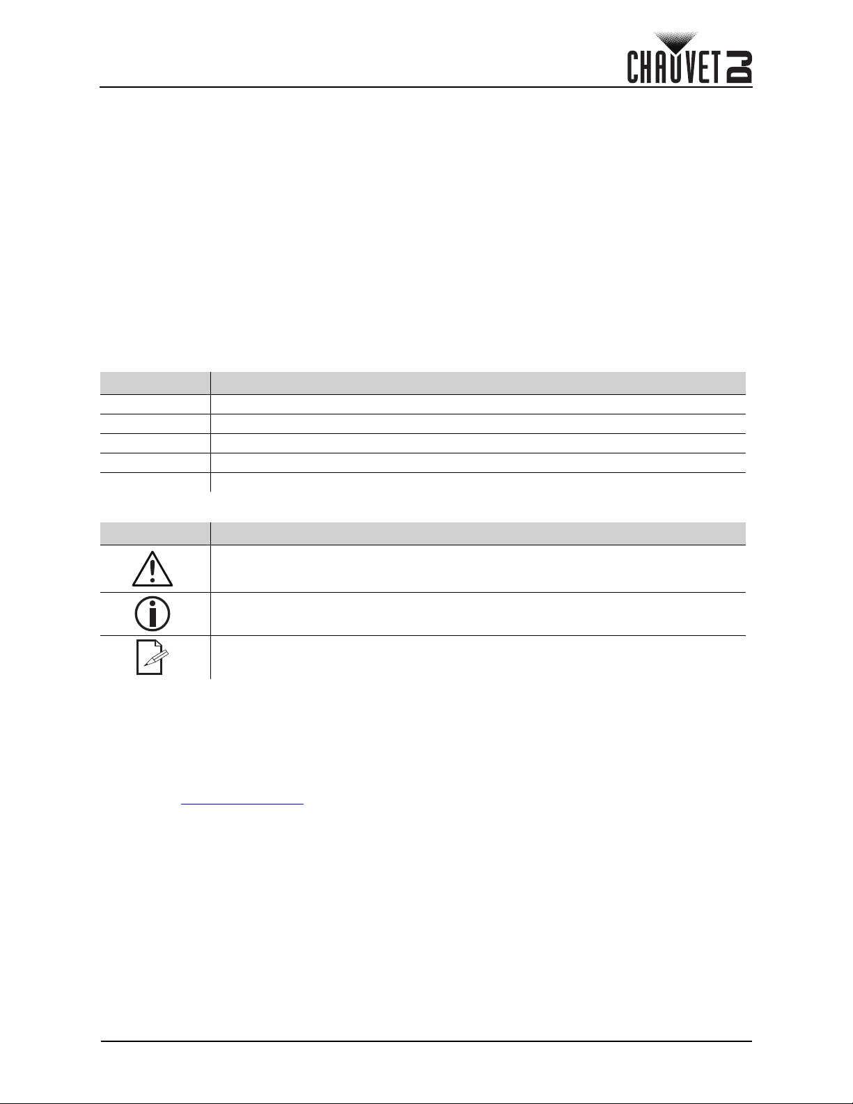
Symbols
Symbol Meaning
Critical installation, configuration, or operation information. Not following these
instructions may make the product not work, cause damage to the product, or cause
harm to the operator.
Important installation or configuration information. The product may not function
correctly if this information is not used.
Useful information.
Disclaimer
Chauvet believes that the information contained in this manual is accurate in all respects. However,
Chauvet assumes no responsibility and specifically disclaims any and all liability to any party for any loss,
damage or disruption caused by any errors or omissions in this document, whether such errors or
omissions result from negligence, accident or any other cause. Chauvet reserves the right to revise the
content of this document without any obligation to notify any person or company of such revision, however,
Chauvet has no obligation to make, and does not commit to make, any such revisions. Download the latest
version from www.chauvetdj.com
.
Intellectual Property
The works of authorship contained in this manual, including, but not limited to, all design, text and images
are owned by Chauvet.
© Copyright 2019 Chauvet & Sons, LLC. All rights reserved.
Electronically published by Chauvet in the United States of America.
CHAUVET, the Chauvet logo, and Intimidator Spot 475Z are registered trademarks or trademarks of
Chauvet & Sons LLC (d/b/a Chauvet and Chauvet Lighting) in the United States and other countries. Other
company and product names and logos referred to herein may be trademarks of their respective
companies.
Intimidator Spot 475Z User Manual Rev. 2
Page 1 of 22
Page 4

Safety Notes
• This product is not intended for permanent installation.
• Always connect the product to a grounded circuit to avoid the risk of electrocution.
• Always disconnect the product from the power source before cleaning or replacing the fuse.
• Avoid direct eye exposure to the light source while the product is on.
• Make sure the power cord is not crimped or damaged.
• Never disconnect the product from power by pulling or tugging on the cord.
• If mounting the product overhead, always secure to a fastening device using a safety cable.
• Make sure there are no flammable materials close to the product when operating.
• Do not touch the product’s housing when operating because it may be very hot.
• The voltage of the outlet to which you are connecting this product must be within the range
stated on the decal or rear panel of the product.
• The product is for indoor use only! (IP20) To prevent risk of fire or shock, do not expose the
product to rain or moisture.
• Always install the product in a location with adequate ventilation, at least 20 in (50 cm) from
adjacent surfaces.
• Be sure that no ventilation slots on the product’s housing are blocked.
• Never connect the product to a dimmer or rheostat.
• Make sure to replace the fuse with another of the same type and rating.
• Never carry the product from the power cord or any moving part. Always use the handles.
• The maximum ambient temperature is 104 °F (40 °C). Do not operate this product at higher
temperatures.
• In the event of a serious operating problem, stop using the product immediately.
• Do not open this product. It contains no user-serviceable parts.
• To eliminate unnecessary wear and improve its lifespan, during periods of non-use completely
disconnect the product from power via breaker or by unplugging it.
Before You Begin
Keep this User Manual for future use. If the product is sold to someone else, be sure that they
also receive this document.
Page 2 of 22
Intimidator Spot 475Z User Manual Rev. 2
Page 5
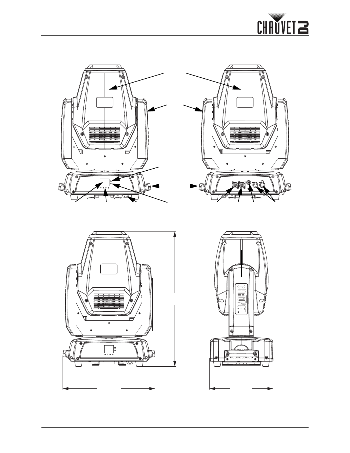
Introduction
DMX
In/Out
Fuse
Holder
Power
In
Menu
Buttons
LED
Display
LED
Indicator
Moving
Head
Yoke
Power
Out
IR Sensor
Safety
Loop
Carry
Handles
20.9 in
531 mm
9.8 in
250 mm
14.3 in
363 mm
2. Introduction
Product Overview
Product Dimensions
Intimidator Spot 475Z User Manual Rev. 2
Page 3 of 22
Page 6
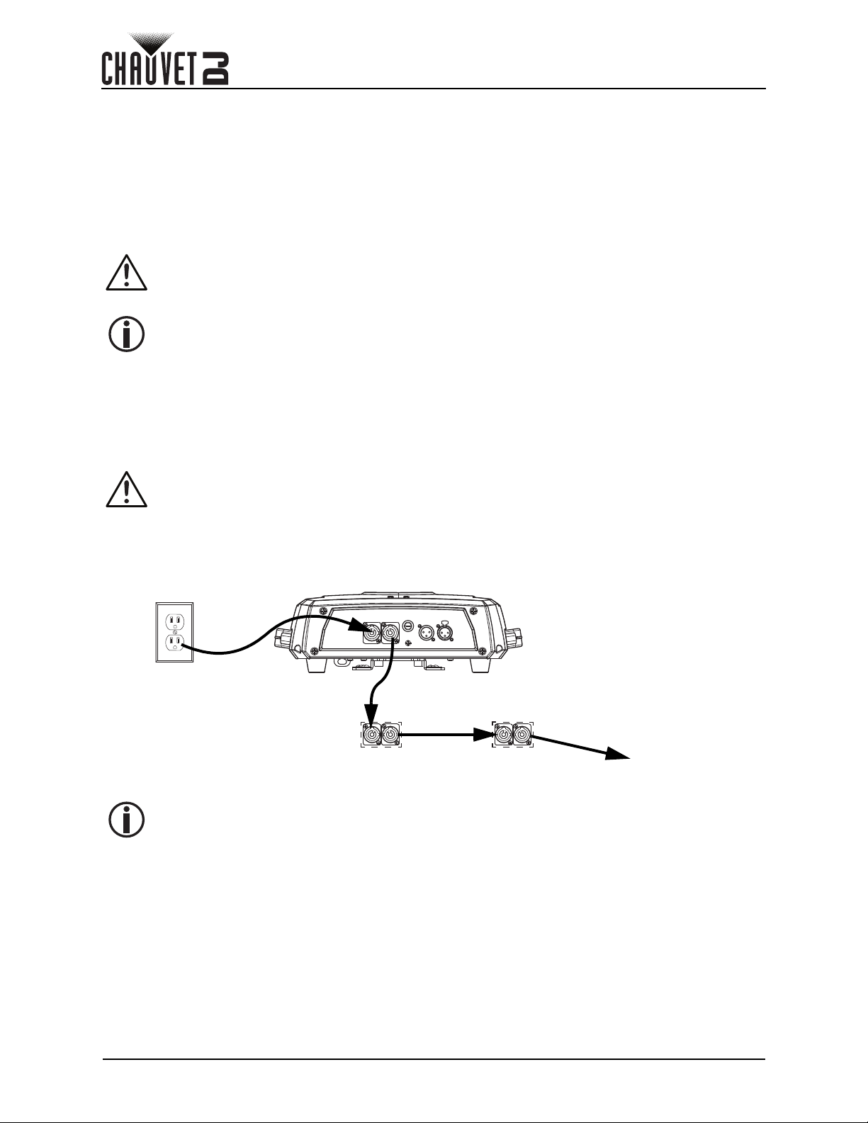
Setup
1st Product
2
nd
Product 3rd Product
Additional
Products
Power
Source
3. Setup
AC Power
The Intimidator Spot 475Z has an auto-ranging power supply and it can work with an input voltage range of
100 to 240 VAC, 50/60 Hz.
To determine the product’s power requirements (circuit breaker, power outlet, and wiring), use the current
value listed on the label affixed to the product’s back panel, or refer to the product’s specifications chart.
The listed current rating indicates the product’s average current draw under normal conditions.
• Always connect the product to a protected circuit (a circuit breaker or fuse). Make sure
the product has an appropriate electrical ground to avoid the risk of electrocution or
fire.
• To eliminate unnecessary wear and improve its lifespan, during periods of non-use
completely disconnect the product from power via breaker or by unplugging it.
Never connect the product to a rheostat (variable resistor) or dimmer circuit, even if the
rheostat or dimmer channel serves only as a 0 to 100% switch.
Fuse Replacement
1. Disconnect the product from power.
2. Using a flat-head screwdriver, unscrew the fuse holder cap from the housing.
3. Remove the blown fuse.
4. Replace with a fuse of the same type and rating.
5. Screw the fuse holder cap back in place and reconnect power.
Disconnect the product from the power outlet before replacing the fuse.
Power Linking
The product provides power linking via the outlet located in the back of the product. See the diagram below
for further explanation.
Power Linking Diagram
You can power link up to 3 Intimidator Spot 475Z products on 120 VAC or up to 5
Intimidator Spot 475Z products on 230 VAC.
Page 4 of 22
Intimidator Spot 475Z User Manual Rev. 2
Page 7
Setup
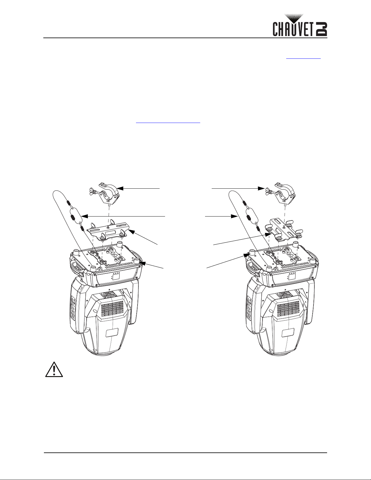
Safety Cable
(such as CH-05
from Chauvet)
Mounting Clamp
(such as CLP-15 from Chauvet)
Mounting Bracket
Feet for Floor
Mounting (x4)
Mounting
Before mounting the product, read and follow the safety recommendations indicated in the Safety Notes.
Orientation
The Intimidator Spot 475Z may be mounted in any position; however, make sure adequate ventilation is
provided around the product.
Rigging
• Before deciding on a location, always make sure there is easy access to the product for
maintenance and programming.
• Make sure adequate ventilation is provided around the product.
• Make sure that the structure or surface onto which you are mounting the product can support the
product’s weight. (see the Technical Specifications
• When mounting the product overhead, always use a safety cable. Mount the product securely to a
rigging point, whether an elevated platform or a truss.
• When rigging the product onto a truss, use a mounting clamp of appropriate weight capacity.
• When power linking multiple products, mount the products close enough for power linking cables to
reach.
• The rubber feet also serve as floor supports and allow for surface mounting. When mounting the
product on the floor, make sure that the product and cables are away from people and vehicles.
Mounting Diagram
)
When using one mounting clamp with this fixture, use a clamp with a captive bolt to
prevent accidental loosening.
Intimidator Spot 475Z User Manual Rev. 2
Page 5 of 22
Page 8
Operation
4. Operation
Control Panel Operation
To access the control panel functions, use the four buttons located underneath the display. Please refer to
the Product Overview
Button Function
<MENU> Exits from the current menu or function
<UP> Navigates upwards through the menu list or increases a selected numeric value
<DOWN> Navigates downwards through the menu list or decreases a selected numeric value
<ENTER> Enables the currently displayed menu or sets a selected value into the selected function
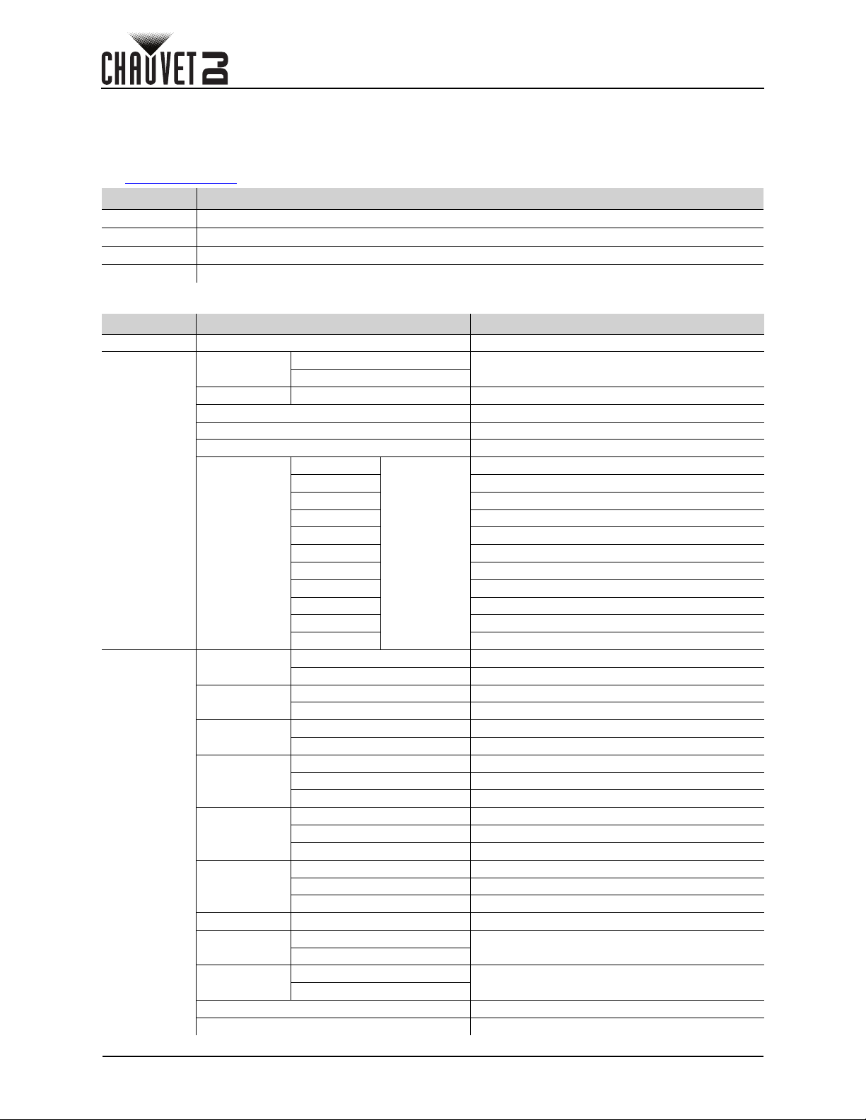
Menu Map
Main Level Programming Levels Description
Address 001–512 Sets the DMX starting address
Run Mode
Setup
to see the button locations on the control panel.
DMX
Slave Slave1–4 Selects Slave mode 1, 2, 3, or 4
Auto Selects Auto mode
Sound Selects Sound-Active mode
Color Manual color wheel control
Gobo Manual rotating gobo wheel control
Gobo Rotate Manual gobo rotation control
Manual
Pan Reverse
Tilt Reverse
Screen
Reverse
Pan Angle
Tilt Angle
Totem Mode
Sensitivity 001–100 Sets the sound sensitivity
Indicator
Flash if DMX
Gobo2 Manual static gobo wheel control
Prism Manual prism control
Focus Manual focus control
Zoom Manual zoom control
Dimmer Manual dimmer control
Shutter Manual shutter control
Reset Resets the product
Factory Set Loads factory defaults
16CH
10CH
IR Selects Infrared control mode
Pan
Tilt Manual tilt control
000–255
OFF Normal pan operation
ON Reverse pan operation
OFF Normal tilt operation
ON Reverse tilt operation
OFF Normal display
ON Reverse display
540 Selects the 540° pan angle range
360 Selects the 360° pan angle range
180 Selects the 180° pan angle range
270 Selects the 270° tilt angle range
180 Selects the 180° tilt angle range
90 Selects the 90° tilt angle range
OFF Does not restrict the pan and tilt motion
UP
DOWN
ON
OFF
ON
OFF
Selects the DMX mode
Manual pan control
Restricts the pan and tilt motion for overhead mount
Restricts the pan and tilt motion for floor mount
Enables/Disables LED indicator
Enables/Disables Flash if DMX
Page 6 of 22
Intimidator Spot 475Z User Manual Rev. 2
Page 9
Operation
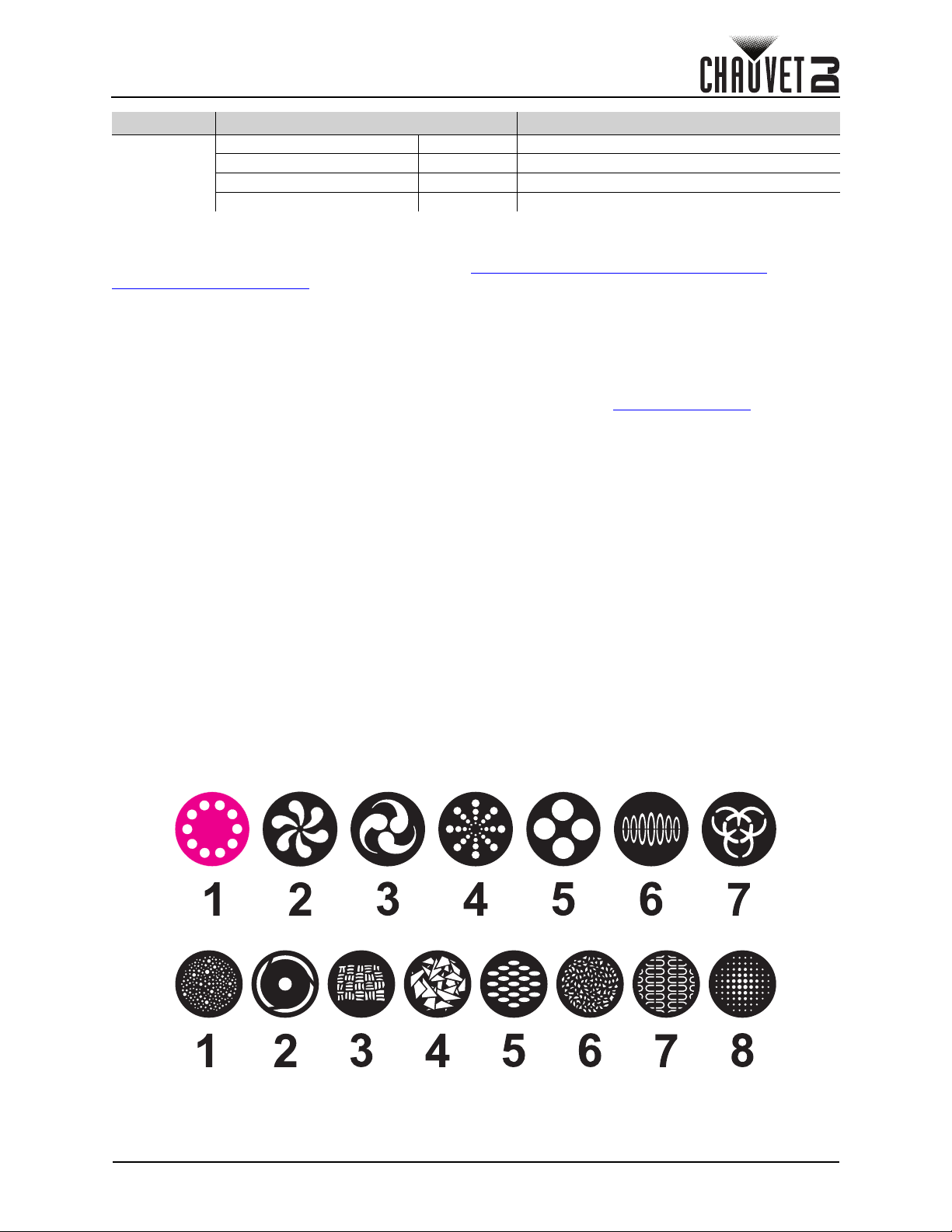
Gobo - Rotating Gobo Wheel
Gobo2 - Static Gobo Wheel
Main Level Programming Levels Description
Ver: V_ Displays the current firmware version
Sys Info
Running Mode: _ _ _ _ _ _ _ Displays the current running mode
DMX Address: _ _ _ Displays the current DMX address
Temperature:
_ _ _ Displays the product temperature in °C
Configuration (DMX)
The Intimidator Spot 475Z works with a DMX controller. Information about DMX is in the CHAUVET DMX
Primer, which is available from the Chauvet website http://www.chauvetlighting.com/downloads/
DMX_Primer_rev05_WO.pdf.
Starting Address
When selecting a starting DMX address, always consider the number of DMX channels the selected DMX
mode uses. If the starting address is set too high, access to some of the product’s channels could be
restricted.
The Intimidator Spot 475Z uses up to 16 DMX channels, which defines the highest configurable address to
497.
For information about the DMX protocol, download the DMX Primer from www.chauvetdj.com
To select the starting address, do the following:
1. Press <MENU>.
2. Use <UP> or <DOWN> to select Address.
3. Press <ENTER>.
4. Use <UP> or <DOWN> to select the starting address, from 001–512.
5. Press <ENTER>.
.
DMX Personalities
The Intimidator Spot 475Z has two DMX personalities, a 16-channel personality, and a 10-channel
personality.
To select a DMX personality, follow the instructions below.
1. Press <MENU>.
2. Use <UP> or <DOWN> to select Run Mode.
3. Press <ENTER>.
4. Use <UP> or <DOWN> to select DMX.
5. Press <ENTER>.
6. Use <UP> or <DOWN> to select the DMX personality, from 16CH or 10CH.
7. Press <ENTER>.
DMX Channel Assignments and Values
Gobos
Intimidator Spot 475Z User Manual Rev. 2
Page 7 of 22
Page 10

16CH
Channel Function Value Percent/Setting
1 Pan 000 255 0–540°
2 Fine Pan 000 255 Fine control of panning
3Tilt 000 255 0–270°
4 Fine Tilt 000 255 Fine control of tilting
5 Pan/Tilt Speed 000 255 Pan/Tilt speed, fast to slow
000 007 White
008 015 Orange
016 023 Lime Green
024 031 Cyan
032 039 Red
040 047 Green
6 Color Wheel
7
8 Gobo Rotation
Rotating Gobo Wheel
(Gobo) (see Gobos
)
048 055 Magenta
056 063 Yellow
064 White
065 189 Color indexing
190 221 Color cycling rainbow, fast to slow
222 223 Stop
224 255 Reverse color cycling rainbow, slow to fast
000 007 Open
008 015 Gobo 1
016 023 Gobo 2
024 031 Gobo 3
032 039 Gobo 4
040 047 Gobo 5
048 055 Gobo 6
056 063 Gobo 7
064 071 Gobo 7 shake, slow to fast
072 079 Gobo 6 shake, slow to fast
080 087 Gobo 5 shake, slow to fast
088 095 Gobo 4 shake, slow to fast
096 103 Gobo 3 shake, slow to fast
104 111 Gobo 2 shake, slow to fast
112 119 Gobo 1 shake, slow to fast
120 127 Open
128 191 Cycle effect, slow to fast
192 255 Reverse cycle effect, slow to fast
000 063 Gobo indexing
064 147 Gobo rotation, slow to fast
148 231 Reverse gobo rotation, slow to fast
232 255 Gobo bounce, short to long
Operation
Page 8 of 22
Intimidator Spot 475Z User Manual Rev. 2
Page 11

Operation
Channel Function Value Percent/Setting
000 006 Open
007 013 Gobo 1
014 020 Gobo 2
021 027 Gobo 3
028 034 Gobo 4
035 041 Gobo 5
042 048 Gobo 6
049 055 Gobo 7
056 063 Gobo 8
9
10 Prism
11 Focus 000 255 Focus, big to small
12 Zoom 000 255 Zoom, wide to narrow
13 Dimmer 000 255 0–100%
14 Shutter
Static Gobo Wheel (Gobo2)
(see Gobos
)
064 071 Gobo 8 shake, slow to fast
072 078 Gobo 7 shake, slow to fast
079 085 Gobo 6 shake, slow to fast
086 092 Gobo 5 shake, slow to fast
093 099 Gobo 4 shake, slow to fast
100 106 Gobo 3 shake, slow to fast
107 113 Gobo 2 shake, slow to fast
114 120 Gobo 1 shake, slow to fast
121 127 Open
128 191 Reverse cycle effect, slow to fast
192 255 Cycle effect, slow to fast
000 003 No function
004 006 Prism 1 (round)
007 065 Prism rotation, slow to fast
066 123 Reverse prism rotation, slow to fast
124
128 131 No function
132 134 Prism 2 (linear)
135 193 Prism rotation, slow to fast
194 251 Reverse prism rotation, slow to fast
252 255 Prism 2 (linear)
000 003 Off
004 007 On
008 076 Strobe, slow to fast
077 145 Pulse strobe, slow to fast
146 215 Random strobe, slow to fast
216 255 On
127 Prism 1 (round)
Intimidator Spot 475Z User Manual Rev. 2
Page 9 of 22
Page 12

Channel Function Value Percent/Setting
000 007 No function
008 015 Blackout on pan/tilt movement
016 023 Blackout on color wheel movement
024 031 Blackout on gobo wheel movement
032 039 Blackout on pan/tilt/color wheel movement
040 047 Blackout on pan/tilt/gobo wheel movement
048 055 Blackout on pan/tilt/color/gobo wheel movement
056 095 No function
15 Function
16 Movement Macro
096 103 Pan reset
104 111 Tilt reset
112 119 Color wheel reset
120 127 Gobo wheels reset
128 135 No function
136 143 Prism reset
144 151 No function
152 159 Reset all
160 255 No function
000 007 No function
008 023 Movement macro 1
024 039 Movement macro 2
040 055 Movement macro 3
056 071 Movement macro 4
072 087 Movement macro 5
088 103 Movement macro 6
104
120 135 Movement macro 8
136 151 Sound-active movement macro
152 167 Sound-active movement macro 2
168 183 Sound-active movement macro 3
184 199 Sound-active movement macro 4
200 215 Sound-active movement macro 5
216 231 Sound-active movement macro 6
232 247 Sound-active movement macro 7
248 255 Sound-active movement macro 8
119 Movement macro 7
Operation
Page 10 of 22
Intimidator Spot 475Z User Manual Rev. 2
Page 13

Operation
10CH
Channel Function Value Percent/Setting
1 Pan 000 255 0–540°
2Tilt 000 255 0–270°
000 007 White
008 015 Orange
016 023 Lime Green
024 031 Cyan
032 039 Red
040 047 Green
3 Color Wheel
4
5 Gobo Rotation
Rotating Gobo Wheel
(Gobo) (see Gobos
)
048 055 Magenta
056 063 Yellow
064 White
065 189 Color indexing
190 221 Color cycling rainbow, fast to slow
222 223 Stop
224 255 Reverse color cycling rainbow, slow to fast
000 007 Open
008 015 Gobo 1
016 023 Gobo 2
024 031 Gobo 3
032 039 Gobo 4
040 047 Gobo 5
048 055 Gobo 6
056 063 Gobo 7
064 071 Gobo 7 shake, slow to fast
072 079 Gobo 6 shake, slow to fast
080 087 Gobo 5 shake, slow to fast
088 095 Gobo 4 shake, slow to fast
096 103 Gobo 3 shake, slow to fast
104 111 Gobo 2 shake, slow to fast
112 119 Gobo 1 shake, slow to fast
120 127 Open
128 191 Cycle effect, slow to fast
192 255 Reverse cycle effect, slow to fast
000 063 Gobo indexing
064 147 Gobo rotation, slow to fast
148 231 Reverse gobo rotation, slow to fast
232 255 Gobo bounce, short to long
Intimidator Spot 475Z User Manual Rev. 2
Page 11 of 22
Page 14

Channel Function Value Percent/Setting
000 006 Open
007 013 Gobo 1
014 020 Gobo 2
021 027 Gobo 3
028 034 Gobo 4
035 041 Gobo 5
042 048 Gobo 6
049 055 Gobo 7
056 063 Gobo 8
6
7Prism
8 Focus 000 255 Focus, big to small
9 Zoom 000 255 Zoom, wide to narrow
10 Shutter
Static Gobo Wheel (Gobo2)
(see Gobos
)
064 071 Gobo 8 shake, slow to fast
072 078 Gobo 7 shake, slow to fast
079 085 Gobo 6 shake, slow to fast
086 092 Gobo 5 shake, slow to fast
093 099 Gobo 4 shake, slow to fast
100 106 Gobo 3 shake, slow to fast
107 113 Gobo 2 shake, slow to fast
114 120 Gobo 1 shake, slow to fast
121 127 Open
128 191 Reverse cycle effect, slow to fast
192 255 Cycle effect, slow to fast
000 003 No function
004 006 Prism 1 (round)
007 065 Prism rotation, slow to fast
066 123 Reverse prism rotation, slow to fast
124
128 131 No function
132 134 Prism 2 (linear)
135 193 Prism rotation, slow to fast
194 251 Reverse prism rotation, slow to fast
252 255 Prism 2 (linear)
000 003 Off
004 007 On
008 076 Strobe, slow to fast
077 145 Pulse strobe, slow to fast
146 215 Random strobe, slow to fast
216 255 On
127 Prism 1 (round)
Operation
Page 12 of 22
Intimidator Spot 475Z User Manual Rev. 2
Page 15

Operation
Configuration (Standalone)
Set the product in one of the standalone modes to control without a DMX controller.
Never connect a product that is operating in any standalone mode to a DMX string
connected to a DMX controller. Products in standalone mode may transmit DMX signals
that could interfere with the DMX signals from the controller.
Automatic Programs
To run the Intimidator Spot 475Z in automatic mode, follow the instructions below:
1. Press <MENU>.
2. Use <UP> or <DOWN> to select Run Mode.
3. Press <ENTER>.
4. Use <UP> or <DOWN> to select Auto.
5. Press <ENTER>.
Sound-Active Mode
To run the Intimidator Spot 475Z in sound-active mode, do the following:
1. Press <MENU>.
2. Use <UP> or <DOWN> to select Run Mode.
3. Press <ENTER>.
4. Use <UP> or <DOWN> to select Sound.
5. Press <ENTER>.
Sound Sensitivity
To set the sound sensitivity on the Intimidator Spot 475Z, follow the instructions below:
1. Press <MENU>.
2. Use <UP> or <DOWN> to select Setup.
3. Press <ENTER>.
4. Use <UP> or <DOWN> to select Sensitivity.
5. Press <ENTER>.
6. Use <UP> or <DOWN> to increase or decrease the sound sensitivity, from 001–100.
7. Press <ENTER>.
The product will only respond to low frequencies of music (bass and drums).
Manual Mode
To operate the Intimidator Spot 475Z manually through the menu, do the following:
1. Press <MENU>.
2. Use <UP> or <DOWN> to select Run Mode.
3. Press <ENTER>.
4. Use <UP> or <DOWN> to select Manual.
5. Press <ENTER>.
6. Use <UP> or <DOWN> to select from Pan, Tilt, Color, Gobo, Gobo Rotate, Gobo2, Prism,
Focus, Zoom, Dimmer, or Shutter.
7. Press <ENTER>.
8. Use <UP> or <DOWN> to increase or decrease the value of the selected function, from 000–255.
9. Press <ENTER>.
10. Repeat steps 6-9 until the product is set as desired.
Intimidator Spot 475Z User Manual Rev. 2
Page 13 of 22
Page 16

Operation
Configuration (Settings)
Pan Reverse
To set the pan orientation on the Intimidator Spot 475Z, follow the instructions below:
1. Press <MENU>.
2. Use <UP> or <DOWN> to select Setup.
3. Press <ENTER>.
4. Use <UP> or <DOWN> to select Pan Reverse.
5. Press <ENTER>.
6. Use <UP> or <DOWN> to select OFF (normal pan orientation) or ON (reverse pan orientation).
7. Press <ENTER>.
Tilt Reverse
To set the tilt orientation on the Intimidator Spot 475Z, do the following:
1. Press <MENU>.
2. Use <UP> or <DOWN> to select Setup.
3. Press <ENTER>.
4. Use <UP> or <DOWN> to select Tilt Reverse.
5. Press <ENTER>.
6. Use <UP> or <DOWN> to select OFF (normal tilt orientation) or ON (reverse tilt orientation).
7. Press <ENTER>.
Screen Reverse
To set the display orientation on the Intimidator Spot 475Z, follow the instructions below:
1. Press <MENU>.
2. Use <UP> or <DOWN> to select Setup.
3. Press <ENTER>.
4. Use <UP> or <DOWN> to select Screen Reverse.
5. Press <ENTER>.
6. Use <UP> or <DOWN> to select OFF (normal display orientation) or ON (reverse display
orientation).
7. Press <ENTER>.
Pan Angle
To set the pan angle range on the Intimidator Spot 475Z, do the following:
1. Press <MENU>.
2. Use <UP> or <DOWN> to select Setup.
3. Press <ENTER>.
4. Use <UP> or <DOWN> to select Pan Angle.
5. Press <ENTER>.
6. Use <UP> or <DOWN> to select from 540 (540°), 360 (360°), or 180 (180°).
7. Press <ENTER>.
Tilt Angle
To set the tilt angle range on the Intimidator Spot 475Z, follow the instructions below:
1. Press <MENU>.
2. Use <UP> or <DOWN> to select Setup.
3. Press <ENTER>.
4. Use <UP> or <DOWN> to select Tilt Angle.
5. Press <ENTER>.
6. Use <UP> or <DOWN> to select from 270 (270°), 180 (180°), or 90 (90°).
7. Press <ENTER>.
Totem Mode
The Totem mode restricts the pan and tilt motions depending on the intended mounting location. To activate the
Totem mode, do the following:
1. Press
2. Use
3. Press
4. Use
5. Press
6. Use
7. Press
<MENU>
<UP>
<ENTER>
<UP>
<ENTER>
<UP>
overhead mounting), or
<ENTER>
or
<DOWN>
or
<DOWN>
or
<DOWN>
.
.
.
.
to select
to select
to select
DOWN
Setup
.
Totem Mode
OFF
(normal range of motion),
(restricts the pan and tilt motion for surface/floor mounting).
.
UP
(restricts the pan and tilt motion for
Page 14 of 22
Intimidator Spot 475Z User Manual Rev. 2
Page 17

Operation
Indicator
To enable or disable the LED indicator, do the following:
1. Press <MENU>.
2. Use <UP> or <DOWN> to select Setup.
3. Press <ENTER>.
4. Use <UP> or <DOWN> to select Indicator.
5. Press <ENTER>.
6. Use <UP> or <DOWN> to select ON (enabled) or OFF (disabled).
7. Press <ENTER>.
Flash if DMX
To enable or disable the LED indicator flashing to indicate DMX, do the following:
1. Press <MENU>.
2. Use <UP> or <DOWN> to select Setup.
3. Press <ENTER>.
4. Use <UP> or <DOWN> to select Flash if DMX.
5. Press <ENTER>.
6. Use <UP> or <DOWN> to select ON (will indicate DMX) or OFF (will not indicate DMX).
7. Press <ENTER>.
Reset
To reset all functions on the Intimidator Spot 475Z, do the following:
1. Press <MENU>.
2. Use <UP> or <DOWN> to select Setup.
3. Press <ENTER>.
4. Use <UP> or <DOWN> to select Reset.
5. Press <ENTER>.
Factory Reset
To restore the Intimidator Spot 475Z to factory default settings, follow the instructions below:
1. Press <MENU>.
2. Use <UP> or <DOWN> to select Setup.
3. Press <ENTER>.
4. Use <UP> or <DOWN> to select Factory Set.
5. Press <ENTER>.
System Information
To view the system information on the Intimidator Spot 475Z, do the following:
1. Press <MENU>.
2. Use <UP> or <DOWN> to select Sys Info.
3. Press <ENTER>
Intimidator Spot 475Z User Manual Rev. 2
Page 15 of 22
Page 18

Operation
BLACK
OUT
AUTO
SOUND
SENSITIVITY
SPEEDSTROBE
%
MANUAL
FADE
RGB
WUVA
+
0
-
123
654
789
IRC-6 Infrared Remote Control
The Intimidator Spot 475Z is compatible with the IRC-6 infrared remote control from Chauvet. To set the
Intimidator Spot 475Z to IR mode, follow the instructions below:
1. Press <MENU>.
2. Use <UP> or <DOWN> to select Run Mode.
3. Press <ENTER>.
4. Use <UP> or <DOWN> to select IR.
5. Press <ENTER>.
IRC-6 Operation
The list below describes which features each button controls:
• <BLACKOUT> - Keeps shutter closed.
• <AUTO> - Activates Auto mode. Use <+>, <->, or <0>–<9> to select an auto
program.
• <SPEED> - Sets Pan/Tilt Speed (in Auto mode). Use <+> or <-> to increase or
decrease the pan/tilt speed from 000 (fastest) to 255 (slowest).
• <SOUND> - Activates Sound mode.
• <STROBE> - Activates Strobe control. Use <+> or <-> to increase or decrease
the strobe speed from 00 (off) to 13, or from 14–20 for a pulse strobe.
• <SENSITIVITY> - Sets Sound Sensitivity. Use <+> or <-> to increase or
decrease the sensitivity from 001 (lowest) to 100 (highest).
• <%> - Sets Dimmer value. Use <+> or <-> to widen or narrow the shutter.
• <MANUAL> - Cycles through static gobos.
• <FADE> - Cycles through static colors.
• <R> - Sets color wheel rotation speed. Use <+> or <-> to increase or decrease
the speed from 000 (slowest) to 100 (fastest). Press <R> to toggle direction.
• <G> - Sets gobo wheel rotation speed. Use <+> or <-> to increase or decrease
the speed from 000 (slowest) to 100 (fastest). Press <G> to toggle direction.
•
<B> - Activates Auto Change Gobo mode.
• <A> - Sets manual Pan/Tilt values. Press <A> to toggle between pan and tilt.
Use <+> or <-> to increase or decrease the pan/tilt value, from 000–255.
• <UV>/<P> - sets manual Zoom and Focus values. Press <UV>/<P> to toggle
between zoom and focus. Use <+> or <-> to increase or decrease the zoom/
focus value, from 000–255.
• <W> - Sets manual Prism values. Use <+> or <-> to increase or decrease the
prism value, from 000–255.
• <+> - Increases a value when in a function.
• <-> - Decreases a value when in a function.
• <0>–<9> - Selects Auto programs 0–9.
Page 16 of 22
Intimidator Spot 475Z User Manual Rev. 2
Page 19

Operation
Master/Slave Mode
The Master/Slave mode allows a single Intimidator Spot 475Z product (the “master”) to control the actions of one
or more Intimidator Spot 475Z products (the “slaves”) without the need of a DMX controller. The master product
will be set to operate in either standalone mode or with the IRC-6, while the slave products will be set to operate
in slave mode. Once set and connected, the slave products will operate in unison with the master product.
Configure the products as indicated below.
Slave products:
1. Press <MENU>.
2. Use <UP> or <DOWN> to select Run Mode.
3. Press <ENTER>.
4. Use <UP> or <DOWN> to select Slave.
5. Press <ENTER>.
6. Use <UP> or <DOWN> to select from Slave1, Slave2, Slave3, or Slave4.
•Select Slave1 for 100% synchronized actions.
•Select Slave2, Slave3, and/or Slave4 for delayed actions, creating a wave effect.
7. Press <ENTER>.
8. Connect the DMX input of the first slave product to the DMX output of the master product.
9. Connect the DMX input of the subsequent slave products to the DMX output of the previous slave
product.
10. Finish setting and connecting all the slave products.
Master product:
1. Set the master product to operate in standalone mode or with the IRC-6.
2. Make the master product the first product in the DMX daisy chain.
• Configure all the slave products before connecting the master to the daisy chain.
• Never connect a DMX controller to a DMX string configured for Master/Slave operation
because the controller may interfere with the signals from the master.
• Do not connect more than 31 slaves to the master.
Zero Adjust Mode
The Intimidator Spot 475Z contains a passcode protected mode which allows the user to calibrate and
adjust several of the product’s operating parameters.
In order to access this mode, do the following:
1. Press and hold <MENU> for at least 3 seconds.
2. Use <UP> (increases the selected value) and <DOWN> (selects the next value) to enter the
passcode: 2323.
3. Press <ENTER>.
In this mode, the starting positions for the following can be adjusted:
Parameter Function
PAN Pan motor
TILT Tilt motor
COLOR Color wheel
GOBO Rotating gobo wheel
GOBO ROTATE Gobo rotation
GOBO2 Static gobo wheel
PRISM1 Round prism
PRISM2 Linear prism
FOCUS Focus assembly
FOCUS-GOBO2 Auto-focus on static gobo wheel
ZOOM Zoom assembly
LED Dimmer value
To adjust the starting position of one of these parameters, follow the instructions below:
1. Access the Zero Adjust mode.
2. Use <UP> or <DOWN> to select the parameter to be adjusted.
3. Press <ENTER>.
4. Use <UP> or <DOWN> to increase or decrease the selected value, from 000–255.
5. Press <ENTER>.
Intimidator Spot 475Z User Manual Rev. 2
Page 17 of 22
Page 20

Changing Gobos
1
2
3
Tension Ring
Gobo
Gobo Holder
Assembly
Pressure Plate
To change the gobos in the Intimidator Spot 475Z, do the following:
1. Turn off and disconnect the product from power.
2. Place the product on a flat, level surface with the front facing up.
3. Remove 4 screws with a Phillips-head screwdriver to remove the cover.
NOTE: If the gobo wheel is not accessible, the wrong cover was removed. Replace the
cover immediately and remove the cover on the opposite side of the Intimidator Spot 475Z.
4. Rotate the gobo wheel until the gobo that needs replacing is accessible.
Operation
5. Separate the gobo holder assembly from the gobo wheel by pushing it forward and up. Be careful
not to push the gobo out of the gobo plate.
6. Extract the gobo holder by pulling it backwards out of the product.
7. On a flat surface, remove the tension ring that holds the gobo in place and remove the gobo from
the gobo plate.
8. Insert a new gobo and secure it in place with the tension ring.
9. To reinsert the gobo holder, slide the tip of the gobo holder under the pressure plate near the
center of the gobo wheel.
10. Push the gobo holder assembly inwards. DO NOT force the gobo holder into the gobo wheel slot.
Move the holder slightly from the side to side if needed to get it to sit properly. If correctly installed,
the bottom of the holder will be flush with the gobo wheel.
11. Replace the cover of the Intimidator Spot 475Z and secure with the 4 screws.
Page 18 of 22
Intimidator Spot 475Z User Manual Rev. 2
Page 21

Maintenance
5. Maintenance
Product Maintenance
Dust build-up reduces light output performance and can cause overheating. This can lead to reduction of
the light source’s life and/or mechanical wear. To maintain optimum performance and minimize wear, clean
your lighting products at least twice a month. However, be aware that usage and environmental conditions
could be contributing factors to increase the cleaning frequency.
To clean the product, follow the instructions below:
1. Unplug the product from power.
2. Wait until the product is at room temperature.
3. Use a vacuum (or dry compressed air) and a soft brush to remove dust collected on the external
surface/vents.
4. Clean all transparent surfaces with a mild soap solution, ammonia-free glass cleaner, or isopropyl
alcohol.
5. Apply the solution directly to a soft, lint free cotton cloth or a lens cleaning tissue.
6. Softly drag any dirt or grime to the outside of the transparent surface.
7. Gently polish the transparent surfaces until they are free of haze and lint.
Always dry the transparent surfaces carefully after cleaning them.
Do not spin the cooling fans using compressed air because it they could be damaged.
Intimidator Spot 475Z User Manual Rev. 2
Page 19 of 22
Page 22

Technical Specifications
UL 1573
CSA C22.2 No. 166
E113093
R
6. Technical Specifications
Dimensions and Weight
Length Width Height Weight
14.3 in (363 mm) 9.8 in (250 mm) 20.9 in (531 mm) 36.2 lb (16.5 kg)
Note: Dimensions in inches rounded to the nearest decimal digit.
Power
Power Supply Type Range Voltage Selection
Switching (internal) 100 to 240 VAC, 50/60 Hz Auto-ranging
Parameter 120 V, 60 Hz 230 V, 50 Hz
Consumption 380 W 378 W
Operating Current 3.4 A 1.9 A
Power linking current (products) 11.2 A (3 products) 11.2 A (5 products)
Fuse F 7 A, 250 V F 7 A, 250 V
Power I/O U.S./Worldwide UK/Europe
Power input connector powerCON®-compatible powerCON®-compatible
Power output connector powerCON®-compatible powerCON®-compatible
Power Cord plug Edison (U.S.) Local Plug
Light Source
Type Color Quantity Power Current Lifespan
LED White 1 250 W 16.3 A 50,000 hours
Photometrics
Parameter Value Parameter Value
Strobe Rate 0 to 20 Hz Illuminance @ 2 m (13°) 106,300 lux
Zoom Angle (Motorized) 13° to 28° Illuminance @ 2 m (28°) 23,680 lux
Illuminance @ 5 m (13°) 14,290 lux
Illuminance @ 5 m (28°) 3,741 lux
Thermal
Maximum External Temperature Cooling System
104 °F (40 °C) Fan-assisted convection
DMX
I/O Connector Channel Range
3-pin XLR 10 or 16
Ordering
Product Name Item Code UPC Number
Intimidator Spot 475Z 08011485 781462218331
Page 20 of 22
Intimidator Spot 475Z User Manual Rev. 2
Page 23

Returns
Returns
In case you need to get support or return a product:
• If you are located in the US, contact Chauvet World Headquarters.
• If you are located in the UK or Ireland, contact Chauvet Europe Ltd.
• If you are located in Benelux, contact Chauvet Europe BVBA.
• If you are located in France, contact Chauvet France.
• If you are located in Germany, contact Chauvet Germany.
• If you are located in Mexico, contact Chauvet Mexico.
• If you are located in any other country, DO NOT contact Chauvet. Instead, contact your local
distributor. See www.chauvetdj.com
Germany, or Mexico.
If you are located outside the US, UK, Ireland, Benelux, France, Germany, or Mexico,
contact your distributor of record and follow their instructions on how to return Chauvet
products to them. Visit our website www.chauvetdj.com
Call the corresponding Chauvet Technical Support office and request a Return Merchandise Authorization
(RMA) number before shipping the product. Be prepared to provide the model number, serial number, and
a brief description of the cause for the return.
To submit a service request online, go to www.chauvetdj.com/service-request
Send the merchandise prepaid, in its original box, and with its original packing and accessories. Chauvet
will not issue call tags.
Clearly label the package with the RMA number. Chauvet will refuse any product returned without an RMA
number.
Write the RMA number on a properly affixed label. DO NOT write the RMA number directly
on the box.
for distributors outside the U.S., UK, Ireland, Benelux, France,
for contact details.
.
Before sending the product, clearly write the following information on a piece of paper and place it inside
the box:
• Your name
• Your address
• Your phone number
•RMA number
• A brief description of the problem
Be sure to pack the product properly. Any shipping damage resulting from inadequate packaging will be
your responsibility. FedEx packing or double-boxing are recommended.
Chauvet reserves the right to use its own discretion to repair or replace returned
product(s).
Intimidator Spot 475Z User Manual Rev. 2
Page 21 of 22
Page 24

Contact Us
Chauvet World Headquarters
Chauvet Europe Ltd
Chauvet Europe BVBA
Chauvet France
Chauvet Germany
Chauvet Mexico
Address: Av. de las Partidas 34 - 3B
Lerma, Edo. de México, CP 52000
General Information Technical Support
Address: 5200 NW 108th Ave. Voice: (844) 393-7575
Sunrise, FL 33351 Fax: (954) 756-8015
Voice: (954) 577-4455 Email: chauvetcs@chauvetlighting.com
Fax: (954) 929-5560
Toll Free: (800) 762-1084 Website: www.chauvetdj.com
Address: Unit 1C Email: UKtech@chauvetlighting.eu
Brookhill Road Industrial Estate
Pinxton, Nottingham, UK Website: www.chauvetdj.eu
NG16 6NT
Voice: +44 (0) 1773 511115
Fax : +44 (0) 177 3 511110
Address: Stokstraat 18 Email: BNLtech@chauvetlighting.eu
9770 Kruishoutem
Belgium Website: www.chauvetdj.eu
Voice: +32 9 388 93 97
Address: 3, Rue Ampère
91380 Chilly-Mazarin
France Website: www.chauvetdj.eu
Voice: +33 1 78 85 33 59
Address: Bruno-Bürgel-Str. 11
28759 Bremen
Germany Website: www.chauvetdj.eu
Voice: +49 421 62 60 20
(Entrance by Calle 2)
Zona Industrial Lerma Website: www.chauvetdj.mx
Voice: +52 (728) 690-2010
Email: FRtech@chauvetlighting.fr
Email: DEtech@chauvetlighting.de
Email: servicio@chauvet.com.mx
Contact Us
Visit the applicable website above to verify our contact information and instructions to request support.
Outside the US, United Kingdom, Ireland, Mexico, France, Germany, or Benelux, contact the dealer of
record
.
Page 22 of 22
Intimidator Spot 475Z User Manual Rev. 2
 Loading...