

Page 1
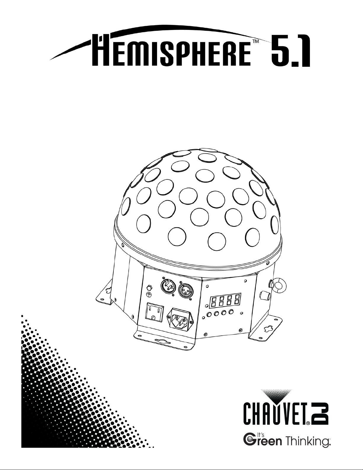
User Manual
Page 2

TABLE OF CONTENTS
1. Before You Begin................................................................................3
What Is Included ........................................................................................... 3
Unpacking Instruc tions .................................................................................. 3
Claims ................................................................................................................... 3
Text Conventions .......................................................................................... 3
Icons ............................................................................................................. 3
Disclaimer ..................................................................................................... 3
Product at a Glance ....................................................................................... 4
Safety Notes ................................................................................................. 4
2. Introduction.........................................................................................5
Product Overview .......................................................................................... 5
Product Dimensions ...................................................................................... 6
3. Setup ...................................................................................................7
AC Power ...................................................................................................... 7
Fus e Repl acement ................................................................................................. 7
Power Linking ........................................................................................................ 8
Mounting ....................................................................................................... 9
Orientation ............................................................................................................. 9
Rigging .................................................................................................................. 9
4. Operation ..........................................................................................10
Control Panel Operation .............................................................................. 10
Menu Map ................................................................................................... 10
Configuration ( DM X) .................................................................................... 11
Starting Address .................................................................................................. 11
DMX Values ................................................................................................ 11
5-CH .................................................................................................................... 11
Configuration ( S tandalone) .......................................................................... 12
Sound-Active Mode .............................................................................................. 12
Automatic Mode ................................................................................................... 12
Master/Sl ave Mode .............................................................................................. 12
5. Technical Information ......................................................................13
Product Maintenanc e .................................................................................. 13
6. Techni cal Sp eci f ications ..................................................................14
Returns ....................................................................................................... 15
Contact Us .................................................................................................. 15
Page 2 of 15 Hemisphere™ 5.1 User Manual Rev. 2
Page 3
What Is
Included
Unpacking
Instructions
included accessories) appear damaged from
omponents or parts, damage not relat ed to shipping,
Text
1 to 512
A range of values
50/60
A set of values of which only one can be chosen
Settings
A menu option not to be modified
Menu > Settings
A seq uence of menu opti ons to b e followed
<ENTER>
A key t o be pr essed on th e product’s control panel
ON
A value t o be entered or selected
Icons
Critical installation, configuration, or operation informa tion. Failure
operator.
Disclaimer
The information and specifications contained in this document are subject to change
without notice. CHAUVET® assumes no responsibility or liability for any errors or
Author
Date
Editor
Date
1. BEFORE YOU BEGIN
Claims
Conventions
• Hemisp here™ 5.1
• Power cord
Immediately upon receipt, carefully unpack the product and check the contai ner to make
sure you have received all the parts indicat ed above in good condition.
If the box or the contents (the product and
shipping, or show signs of mishandling, notify the carrier immediately, not CHAUVET®.
Failure to do so in a timely m anner may invali date y our claim with the carrier. I n addition,
keep the box and contents for inspect ion.
For other issues such as missing c
or concealed damage, file a claim with CHAUVET® within 7 days of delivery.
Convention Meaning
Icon Meaning
• Warranty card
• Quick Reference G uide
omissions that may appear i n this manual, and res erves the r ig ht to revi se o r rec reat e
this manual at any time.
Download the latest version of this document from www.chauvetlighting.com.
© Copyright 2013 CHAUVET®. All rights reserved.
Printed in P.R.C.
Electronically published by CHAUVET® in the U nited St ates of Am er ica.
to comply may render the product partially or completely
A. Leon 07/24/13 T. Yeago 07/24/13
inoperative, cause dam age to the product, or cause harm to the
Important installation or configuration information. The product
may not function correctly if this i nformation i s not us ed.
Useful information.
Hemisphere™ 5.1 User Manual Rev. 2 Page 3 of 15
Page 4
Product at a
x
P
x
P
P
P
P
x
P
x
Safety Notes
, usage, and
Glance
Use on Dimmer
Out door Use
Sound Activated
DMX
Master/Slave
The Safety Notes i nclude important safety i nformation about the mounting
maintenance of this product. Rea d th e Safety Notes b efore using th e pro duct.
• Always connect the product to a grounded circ uit to avoid the risk of electrocution.
• Always disconnect the product from the power source before cleaning or replacing
the fuse.
• Avo id di rect eye exp osure to the l ight sour ce whi le th e product is on.
• Make sure the power cord is not crimped or damaged.
• Never disconnect the product from power by p ul li ng or tugging on the c ord.
• If mounting the product overhead, always use a safety cable.
• Make sure th ere are no flammable materials close t o the product when operating.
• Do not touch the product’s housing when operating because it may be very hot.
• Alw ays make s ure that the voltag e of the outlet to which you are connect ing the
product is within the range stated on the decal or rear panel of the product.
• The product is for indoor us e only! (I P20) T o prevent risk of fire or shock, do n ot
expose the product to rain or moistu re.
• Always install the product in a location with adequate ventilation, at least 20 i n
(50 cm) from adjacent surfaces .
• Be su re that no ventilation slots on the product’s housing are blocked.
• Nev er co nnect the product to a dimmer.
• Make sure to repl ace the fus e w ith a noth er of t he same typ e and r ati ng.
• Nev er ca r ry the product by the power cord or the moving head. Always us e the
hanging/mounting brackets.
• The maximum ambient t emperature (Ta) is 104 °F (40 °C) . Do not operate the
product at higher temperatures.
• In the event of a serious operating problem, stop using the product immediately.
• Nev er tr y to repair the product. Repairs carried out by unskill ed persons can lead to
damage or malfunction. Contact th e near est a uthorized techni cal assistance center.
• This product is not intended for permanent installation.
Auto Programs
Auto-ranging Power Supply
Replaceable Fuse
User-Serviceable
Duty Cycle
• Keep this User Manual for future consultation. If you sell the product to another
user, b e s ure that they also r eceive th is document.
Page 4 of 15 Hemisphere™ 5.1 User Manual Rev. 2
Page 5
2. INTRODUCTION
Product
The Hemisphere™ 5.1 is a rotating, multi-colored centerpiece light. The product
music. Standalone modes allow customized looks without a DMX controller.
DMX In/O ut
Power In/O ut
Safety Loop
Control Panel
contains r ed, green , blue, white, and amb er LEDs for effects similar to a mirror ball.
Overview
The moving head spins in both directions and at variable speeds to create an everchanging star field. Sound-activated programs change the lights to the beat of the
Sound Sensitivity
Adjustment Knob
Hemisphere™ 5.1 User Manual Rev. 2 Page 5 of 15
Page 6

Product Dimensions
Page 6 of 15 Hemisphere™ 5.1 User Manual Rev. 2
Page 7

AC Power
ranging power supply and it can work with an input
(circuit breaker or fuse). Make
an appropriate electrical ground to avoid the risk of
a rheostat (variable resistor) or dimmer circuit, even
Fuse
Installed fuse
(held by plastic clip)
Spare fuse holder
(inside safety cap)
Safety cap
3. SETUP
The Hem i sph er e™ 5. 1 has an autovoltage range of 100~240 VAC, 50/60 Hz.
To determine the product’s power requirements (circuit breaker, power outlet, and
wiring), use the current value li sted on the label affixed to the product’s back panel, or
refer to the product’s specifications chart. The listed current rating indicates the
product’s average current draw under normal condition s.
Always connect the product to a protected circuit
sure the product has
electrocution or fire.
Never connect the product to
if the rheostat or dimmer channel serves only as a 0 to 100% switch.
Replacement
Follow the instructions below to change the fuse, if necessary.
Disconnect the product from power before replacing the fuse.
1. Wedge the tip of a flat-head screwdriver into the slot of the fuse holder.
2. Pry the fuse holder out of the housing.
3. Remove the blown fuse from the holder and replace wi th a fuse of the exact same
type and rating.
4. Insert the fus e holder ba ck into place and reconnect power.
The product does not ship with a spare fuse; however, the safety cap has room
for a spare.
Hemisphere™ 5.1 User Manual Rev. 2 Page 7 of 15
Page 8

Power Linking
of the unit.
The power linking diagram shown above corresponds to the North American
in other markets, you must
consult with the local CHAUVET® distributor as power linking connectors and
1st Product
2nd Product
Other products
3rd Product
The product provides power linking via the IEC out let lo cated in the back
Please see the diagram below for further explanation.
Power Linking
Diagram
You can power link up to 25 Hemisphere™ 5.1 products on 120 VAC or up to 45
Hemisphere™ 5.1 products on 230 VAC.
version of the product ONLY! If using the product
requirements may differ in your country or region.
Page 8 of 15 Hemisphere™ 5.1 User Manual Rev. 2
Page 9

Mounting
, read and follow the safety recommendations indicated in
may be mounted in any position; however, make sure adequate
Rigging
Mount the
on the floor,
Safety
Loop
Mounting Hole
Before mounting the product
the Safety Notes.
Orientation
The Hem i sph ere™ 5. 1
ventilation is provided around the product.
• Before deciding on a location for the product, always make sure there is easy
access to the product for ma intenance and programming purposes.
• Make su re th at th e str uctur e or surface onto which you are mounting the product
can support the product’s weight (see the Technical Specifications
).
• When mounting the product overhead, always use a safety cable.
product securely to a rigging p oint , such as an elevated plat form or a tr uss.
• When rigging the product onto a truss, you should use a mounting clamp of
appropriate weight capacity.
• When power linking multiple products, you must al way s cons id er th e leng th of th e
power linking cable and mount the products close enough for th e cable to reach.
• This product has 4 mounting brackets. The mounting brackets also serve as floor
supports and allow for surfac e mounting. When mounting the product
make sure th at the product and cables a re away from people and vehicles.
Mounting Diagram
Mounting
Brackets
Hemisphere™ 5.1 User Manual Rev. 2 Page 9 of 15
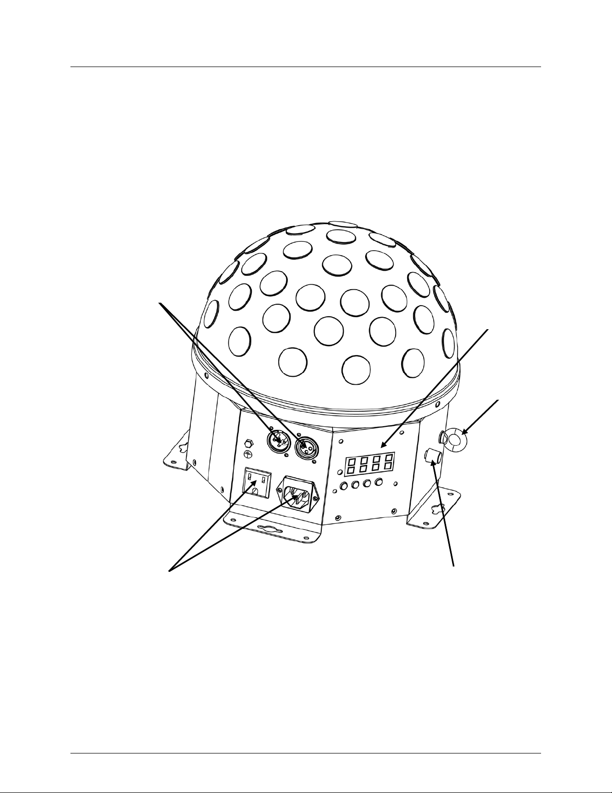
Page 10

Control Panel
Operation
To access the control panel functions, use the four buttons located underneath the
<ENTER>
Press t o acti vate a menu option or a selected value
Menu Map
Main Level
Programming Levels
Description
Auto Program
Selection
Auto Program
Sequence
DMX Address
d.XXX
d.001~d.512
Selects DMX starting address
Slave Mode
SLAV
Sets Sl ave mode
Sound-Active
Mode
C.L.r-
Static color Red
C.L.g-
Static color Green
C.L.b-
Static color Blue
C.L.u-
Static color White
C.L.Y-
Static color Amb er
C.L.rg
Static color Red & Green
C.L.rb
Static color Red & B lue
C.L.ru
Static color Red & White
C.L.rY
Static color Red & Amber
C.L.gb
Static color Green & Bl ue
C.L.gu
Static color Green & White
C.L.gY
Static color Green & Amber
C.L.bu
Static color Blu e & White
C.L.bY
Static color Blu e & Amber
C.L.uY
Static color White & Amber
rgb-
Static color Red, G reen & B lue
rgbu
Static color Red, G reen, Bl ue & White
rgbY
Static color Red, G reen, Bl ue & Amber
C.L.FL
Static color All
4. OPERATION
display. Plea se refer to the Introduction section for button locations on the control panel.
Button Function
<MENU>
Press to find an operation mode or to back out of the current menu
option
<UP> Press t o scrol l up t he li st of opti ons or t o fin d a higher v alue
<DOWN> Press t o scrol l down the list of options or to fi nd a low er value
Pr.XX Pr.01~Pr.14 Selects Auto Program manual ly
AUTO Runs Auto Programs au t omatical ly
SOUN Sets Sound-Active mode
Static Colors C.L.XX
Page 10 of 15 Hemisphere™ 5.1 User Manual Rev. 2
Page 11

Configuration
the selected DMX mode uses. I f you choose a starting address that is too high, you could
512 DMX channels in DMX mode, which defines the
unfamiliar with DMX, download the DMX Primer from
DMX Values
000 ó 009
230 ó 255
Blackout
Sound-Active mode
000 ó 009
010 ó 255
No Function
Strobe (0~13 Hz)
3
Auto Program Speed
000 ó 255
0~100% (Ch. 1: 200~229)
000 ó 009
130 ó 255
Stop
Rotate right (slow to fast)
5
Dimmer
000 ó 255
0~100%
Set the p r oduct in DM X mod e to con trol with a DMX controller.
(DMX)
1. Connect the product to a suitable power outlet.
2. Turn the product on.
3. Connect a DMX cabl e from the DMX out put of the DMX controll er to the DMX input
socket on the product.
Starting Add ress
Wh en selec ting a s tart ing DMX addres s, alw ays co nsider the num ber of DMX cha nnels
restrict the access to some of the product ’s channels.
The Hemisphere™ 5.1 uses up to
highest configurable address to 508.
If unfamiliar with DMX, download the DMX Primer from the CHAUVET® website.
To select the starting address, do the following:
1. Press <MENU> repeatedl y until 5ch shows on the display. If DMX address already
displays, go to step 3.
2. Press <ENTER> to display DMX ad dress.
3. Use <UP> or <DOWN> to sel ect t he st arting addres s.
4. Press <ENTER>.
If you are
www.chauvetlighting.com.
5-CH
Channel Function Value Setting
010 ó 019
020 ó 029
030 ó 039
040 ó 049
050 ó 059
060 ó 069
070 ó 079
080 ó 089
090 ó 099
1 Auto Programs
100 ó 109
110 ó 119
120 ó 129
130 ó 139
140 ó 149
150 ó 159
160 ó 169
170 ó 179
180 ó 189
190 ó 199
200 ó 229
2 Strobe
4 Rotation
010 ó 119
120 ó 129
Hemisphere™ 5.1 User Manual Rev. 2 Page 11 of 15
Red
Green
Blue
White
Amber
Red/Green
Red/Blue
Red/White
Red/Amber
Green/Blue
Green/White
Green/Amber
Blue/White
Blue/Amber
White/Amber
Red/Green/Blue
Red/Green/Blue/White
Red/Green/Blue/Amber
Red/Green/Blue/White/Amber
Auto Program
Rotate left (slow to fast)
Stop
Page 12

Configuration
(Standalone)
to a DMX string connected to a DMX controller.
may transmit DMX signals that could interfere with
Active
Master/Slave
need of a DMX controll er. The master unit will be set to operate in ei ther Automatic or
all the slave units before connecting the master unit to the DMX
Never connect a DMX controller to a DM X string configured for Master/Slave
may interfere with the signals from the
To control the product w ith out a DM X controller, connect the product t o a suitable power
outlet and set the product in one of t he three st andalone modes below.
Never connect a product that is operating in any standalone mode (Sound-Active,
Automatic, or Master/Slave)
Products in standalone mode
the DMX signals from the controller.
Sound-
Mode
To enable the Sound-Active mode, follow the instructions below:
1. Press <MENU> repeatedl y until SoUn shows on the display.
2. Press <ENTER>.
3. Turn the music on and adjust the microphone sensitivity knob until the product
starts responding to the beat of the music.
The product will only respond to low frequencies of music (bass and drums).
Automatic Mode
To enable an Automatic mode, foll ow the instructions below.
Manual ly select i ng an Auto program:
1. Press <MENU> repeatedl y until Pr.XX shows on the displ ay.
2. Press <ENTER>.
3. Use <UP> or <DOWN> to select the automatic program from Pr.01 to Pr.14.
4. Press <ENTER>.
Automa t ically run ning an Auto program:
1. Press <MENU> repeatedly unt i l AUTO shows on the display.
2. Press <ENTER>.
The Master/Slave mode allows a single Hemisphere™ 5.1 product (the “master”) to
Mode
control the actions of one or more Hemi sph ere™ 5. 1 product ( the “s lav es”) with out t he
Sound-Active mode, while the slave units will be set to operate in Slave mode. Once s et
and connected, the slave units will operate in unison with the master unit.
Configure the units as indicated below.
Slave un its:
1. Press <MENU> repeatedly u ntil SLAU shows on the display.
2. Press <ENTER> to accept.
3. Set th e D M X address to d.001.
4. Connect the DMX input of the first slave unit to the DMX output of the master unit.
5. Connect the DMX input of the subsequent slave units to the DMX output of the
previous slave uni t.
6. Finish setting and connecting all the slave units.
Master unit:
1. Set th e m aster unit to opera te i n either Automa t ic or Sound-Active mode.
2. Make the master unit is th e first unit within the DMX dai sy chain.
• Configure
daisy chain.
•
operation because the controller
master unit.
• Do not connect more than 31 sl ave units to the master unit.
Page 12 of 15 Hemisphere™ 5.1 User Manual Rev. 2
Page 13

Product
5. TECHNICAL INFORMATION
Dust build-up reduces light output performance and can cau se overheati ng. This can
Maintenance
lead to reduction of the light source’s life and m echa nical wear. To m aint ain o ptimum
performance and minimize wear, you should clean your lighting products at lea st twice a
month. However, be aware that usage and environmental conditions could be
con tributing fact ors to increase the cleaning frequency.
To clean the product, follow the instructions below.
• Unplug the product from power.
• Wait until the product is at room temperature.
• Use a vacuum (or dry compressed air) and a sof t brush t o r emov e dust collected on
the external sur face.
• Clean all ext erna l optic s and transparent surface s wi th a mild soap solution ,
ammonia-free glass cleaner, or isopropyl alcohol.
• Apply the solution directly to a soft, lint-free cotton cloth or a l ens cleaning tissue.
• Softly drag any dirt or grime off the transparent surfaces.
• Gently polish the transparent surfaces until they are free of haze and lint.
Always dry the external transparent surfaces carefully after cleaning them.
Hemisphere™ 5.1 User Manual Rev. 2 Page 13 of 15
Page 14

Dimensions and
Length
Width
Height
Weight
10.7 in (272 mm)
10.7 in (272 mm)
10 in (254 mm)
6.4 lb (2.9 kg)
Note: Dimensions in inches rounded to the nearest decimal digit.
Power
Power Supply Type
Range
Voltage Selection
Switching (internal)
100~240 VAC, 50/60 Hz
Auto-ranging
Parameter
120 V, 60 Hz
230 V, 50 Hz
Consumption
38 W
43 W
Operating current
0.4 A
0.2 A
Power linking current (units)
8 A (25 units)
8 A (45 units)
Fuse
T 1 A, 250 V
T 1 A, 250 V
Power I / O
US/Worldwide
UK/Europe
Power input connector
IEC
IEC
Power output connector
Edison
IEC
Power Cord plug
Edison (US)
Local plug
Light Source
Type
Power
Lifespan
LED
3 W
50,000 h ours
Color
Quantity
Current
Red
1
730 mA
Green
1
730 mA
Blue
1
730 mA
White
1
730 mA
Amber
1
730 mA
Photo Optic
Parameter
Value
Coverage Angle
360º
Thermal
Maximum External Temp.
Cooling Syste m
104 °F (40 °C)
Convection
DMX
I/O Connectors
Connector Type
Channel Range
3-pin XLR
Sockets
5
Ordering
Product Name
Item Code
Item Numb er
Hemis phere 5.1
03050164
HEMISPHERE5.1
6. TECHNICAL SPECIFICATIONS
Weight
Page 14 of 15 Hemisphere™ 5.1 User Manual Rev. 2
Page 15

Returns
s to
Tech Support office and request a Return
provide the model number, serial number, and a brief description of the cause for the
You must send the merchandise prepaid, in its original box, and with its original packing
the following information on a piece of paper
properly. Any shi pping damage resulting from inadequate
reserves the right to use its own discretion to repair or replace
Contact Us
Fax: +44 (0)1773 511110
Email: tech@chauvetlighting.com
www.chauvetlighting.com
www.chauvetlighting.co.uk
In case y ou need to return a product or request s upport, follow the procedure below:
• If y ou live in the U.S., contact CHAUVET® World Headquarters (see below).
• If you live in the UK or Ireland, contact CHAUVET® Europe Ltd. (see below).
• If you live in any other country, DO NOT contact CHAUVET®. Instead, contact your
distributor of record. See www.chauvetlighting.com
for distributors outside the U.S.,
United Kingdom, or Ireland.
If you live outside the U.S., United Kingdom, or Ireland, contact your distributor of
record and follow their instructions on how to return CHAUVET® product
them. Visit our website for contact details.
Call the corresponding CHAUVET®
Merchandise Authorization (RMA) number before shipping the product. Be prepared to
return.
and accessories. CHAUVET® will not issue call tags.
Clearly mark the package with the RMA number on t he label. CHAUV ET® wil l ref use
any product returned without an RMA number.
Write the RMA number on a properly affixed label. DO NO T wr i t e th e RM A number
directly on the box.
Before sending the product, clea rly wr ite
and place it inside the box:
• Your name
• Your address
• Your phone number
• RMA number
• A brief description of the problem
Be su re to p ack th e product
packaging will be your responsibility. FedEx packing or double-boxing is recommended.
CHAUVET®
returned product(s).
World Headquart ers
CHAUVET®
General Inform ation
Address: 5200 NW 108th Avenue
Sunrise, FL 33351
Voice: (954) 577-4455
Fax: (954) 929-5560
Toll free: (800) 762-1084
Technical Support
Voice: (954) 577-4455 (Press 4)
Fax: (954) 756-8015
World Wide Web
United Kingdom & Ireland
CHAUVET® Europe Ltd.
General Inform ation
Address: Unit 1C
Brookhill Road Industrial Estate
Pinxton, Nottingham, UK
NG16 6NT
Voice: +44 (0)1773 511115
Technical Support
Email: uktech@chauvetlighting.com
World Wide Web
Hemisphere™ 5.1 User Manual Rev. 2 Page 15 of 15
 Loading...