

Page 1
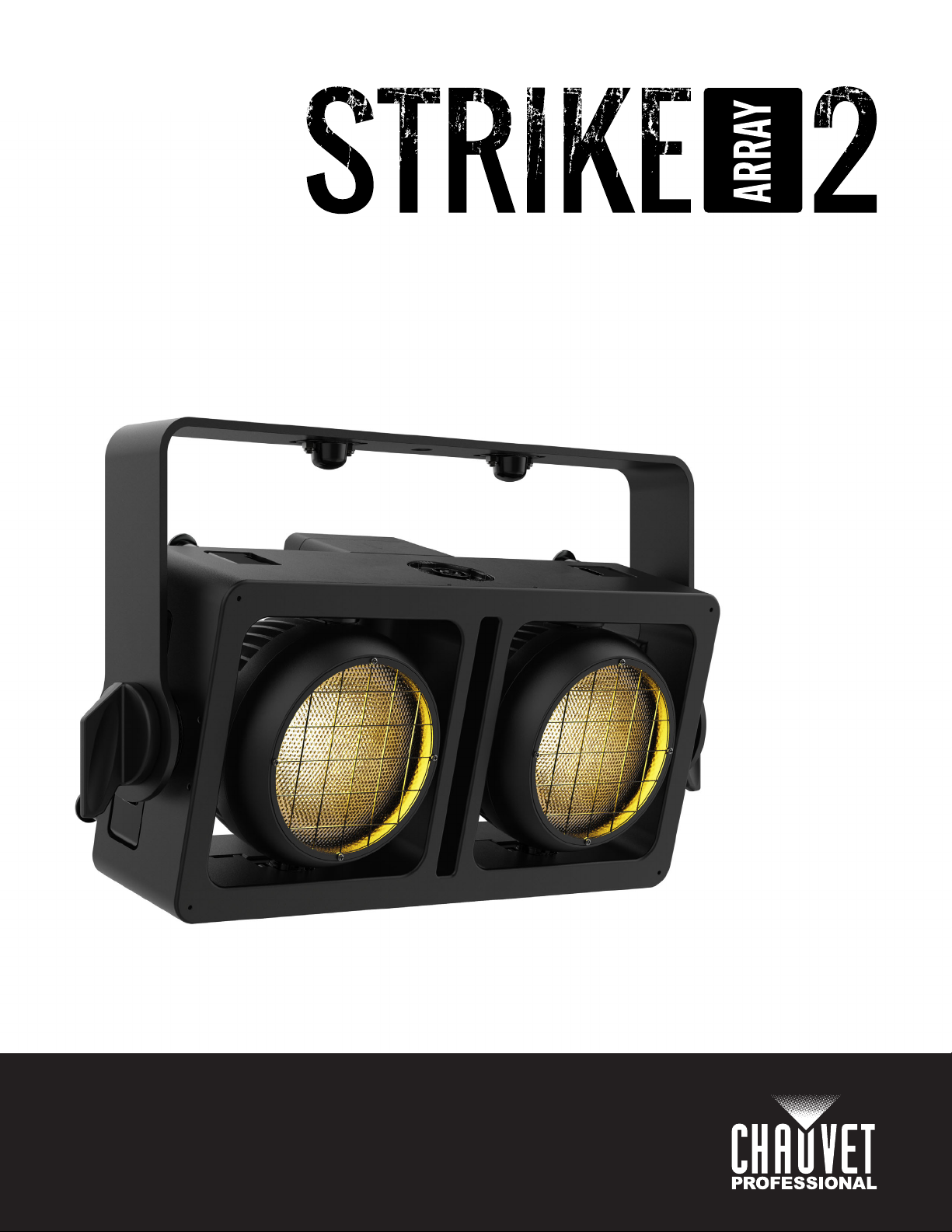
User Manual
Model ID: STRIKEARRAY2
Page 2

Edition Notes
The Strike Array 2 User Manual includes a description, safety precautions, installation, programming,
operation and maintenance instructions for the Strike Array 2 as of the release date of this edition.
Trademarks
CHAUVET, the Chauvet logo and Strike Array 2 are registered trademarks or trademarks of Chauvet &
Sons, LLC (d/b/a Chauvet and Chauvet Lighting) in the United States and other countries. Other company
and product names and logos referred to herein may be trademarks of their respective companies.
Copyright Notice
The works of authorship contained in this manual, including, but not limited to, all design, text and images
are owned by Chauvet.
© Copyright 2021 Chauvet & Sons, LLC. All rights reserved.
Electronically published by Chauvet in the United States of America.
Manual Use
Chauvet authorizes its customers to download and print this manual for professional information purposes
only. Chauvet expressly prohibits the usage, copy, storage, distribution, modification, or printing of this
manual or its content for any other purpose without written consent from Chauvet.
Document Printing
For best results, print this document in color, on letter size paper (8.5 x 11 in), double-sided. If using A4
paper (210 x 297 mm), configure the printer to scale the content accordingly.
Intended Audience
Any person installing, operating, and/or maintaining this product should completely read through the guide
that shipped with the product, as well as this manual, before installing, operating, or maintaining this
product.
Disclaimer
Chauvet believes that the information contained in this manual is accurate in all respects. However,
Chauvet assumes no responsibility and specifically disclaims any and all liability to any party for any loss,
damage or disruption caused by any errors or omissions in this document, whether such errors or
omissions result from negligence, accident or any other cause. Chauvet reserves the right to revise the
content of this document without any obligation to notify any person or company of such revision, however,
Chauvet has no obligation to make, and does not commit to make, any such revisions. Download the latest
version from www.chauvetprofessional.com
.
Document Revision
This Strike Array 2 User Manual is the 2nd edition of this document. Go to www.chauvetprofessional.com
for the latest version.
Strike Array 2 User Manual Rev. 2
Page 3

Table of Contents
TABLE OF CONTENTS
1. Before You Begin ....................................................................... 1
What Is Included ........................................................................................... 1
Claims ........................................................................................................... 1
Text Conventions .......................................................................................... 1
Symbols ........................................................................................................ 1
Safety Notes.................................................................................................. 2
Personal Safety.................................................................................................. 2
Mounting and Rigging ........................................................................................ 2
Power and Wiring............................................................................................... 2
Operation ........................................................................................................... 2
Expected LED Lifespan................................................................................. 2
2. Introduction ................................................................................ 3
Description .................................................................................................... 3
Features........................................................................................................ 3
Product Overview.......................................................................................... 3
Product Dimensions ...................................................................................... 4
3. Setup ........................................................................................... 5
AC Power...................................................................................................... 5
AC Plug .............................................................................................................. 5
Power Linking..................................................................................................... 5
Remote Device Management (RDM) ............................................................ 5
USB Software Update ................................................................................... 5
Mounting ....................................................................................................... 6
Orientation.......................................................................................................... 6
Rigging ............................................................................................................... 6
Procedure........................................................................................................... 6
Product Mounting Diagram ...................................................................................... 6
Multi-Product Mounting ...................................................................................... 7
Multi-Product Mounting Diagram ............................................................................. 7
Mounting Products Attached in Series .................................................................... 8
Vertical Mounting Stability ....................................................................................... 9
4. Operation .................................................................................... 10
Control Panel Description ............................................................................. 10
Control Options ............................................................................................. 10
Programming................................................................................................. 10
Passcode ...................................................................................................... 10
Menu Map ..................................................................................................... 10
Configuration (DMX) ..................................................................................... 11
Control Personalities .......................................................................................... 11
Starting Address................................................................................................. 11
Control Channel Assignments and Values.................................................... 12
8 Ch.................................................................................................................... 12
5 Ch.................................................................................................................... 12
4 Ch.................................................................................................................... 13
3 Ch.................................................................................................................... 13
2 Ch.................................................................................................................... 13
1 Ch.................................................................................................................... 13
Strike Array 2 User Manual Rev. 2
i
Page 4

Table of Contents
Configuration (Standalone) ........................................................................... 14
Static Color......................................................................................................... 14
Automatic Program ............................................................................................ 14
Configuration (Settings) ................................................................................ 14
Red Shift ............................................................................................................ 14
Master Slave ...................................................................................................... 14
Dimmer Mode..................................................................................................... 14
Pulse Width Modulation ..................................................................................... 14
Display Back Light.............................................................................................. 14
Key Lock ............................................................................................................ 14
Product Information............................................................................................ 14
Temperature....................................................................................................... 14
Factory Reset..................................................................................................... 14
5. Maintenance................................................................................ 15
Product Maintenance .................................................................................... 15
6. Technical Specifications ........................................................... 16
Returns............................................................................................ 17
Contact Us ...................................................................................... 18
ii
Strike Array 2 User Manual Rev. 2
Page 5
Before You Begin
1. Before You Begin
What Is Included
•StrikeArray2
• Seetronic Powerkon IP65 power cord
Claims
Carefully unpack the product immediately and check the container to make sure all the parts are in the
package and are in good condition.
If the box or the contents (the product and included accessories) appear damaged from shipping, or show
signs of mishandling, notify the carrier immediately, not Chauvet. Failure to report damage to the carrier
immediately may invalidate your claim. In addition, keep the box and contents for inspection.
For other issues, such as missing components or parts, damage not related to shipping, or concealed
damage, file a claim with Chauvet within 7 days of delivery.
Text Conventions
Convention Meaning
1–512 A range of values
50/60 A set of values of which only one can be chosen
Settings A menu option not to be modified
<ENTER> A key to be pressed on the product’s control panel
Symbols
• Omega bracket with mounting hardware
• Quick Reference Guide
Symbol Meaning
Critical installation, configuration, or operation information. Not following these
instructions may make the product not work, cause damage to the product, or cause
harm to the operator.
Important installation or configuration information. The product may not function
correctly if this information is not used.
Useful information.
Any reference to data or power connections in this manual assumes the use of Seetronic
IP rated cables.
The term “DMX” used throughout this manual refers to the USITT DMX512-A digital data
transmission protocol.
Strike Array 2 User Manual Rev. 2
Page 1 of 18
Page 6

Before You Begin
Safety Notes
Read all the following safety notes before working with this product. These notes contain important
information about the installation, usage, and maintenance of this product.
This product contains no user-serviceable parts. Any reference to servicing in this User
Manual will only apply to properly trained, certified technicians. Do not open the housing
or attempt any repairs.
All applicable local codes and regulations apply to proper installation of this product.
Personal Safety
• Avoid direct eye exposure to the light source while the product is on.
• Always disconnect the product from the power source before cleaning or replacing the fuse.
• Always connect the product to a grounded circuit to avoid the risk of electrocution.
• Do not touch the product’s housing when operating because it may be very hot.
Mounting and Rigging
• Do not submerge this product (IP65). Temporary outdoor operation is fine.
• When using this product in an outdoor environment, use IP65 (or higher) rated power and data
cables. Secure unused power and data ports with attached IP65 covers.
• CAUTION: When transferring product from extreme temperature environments, (e.g., cold truck to
warm, humid ballroom) condensation may form on the internal electronics of the product. To avoid
causing a failure, allow product to fully acclimate to the surrounding environment before connecting
it to power.
• Not for permanent outdoor installation in locations with extreme environmental conditions. This
includes, but is not limited to:
• Exposure to a marine/saline environment (within 3 miles of a saltwater body of water).
• Locations where the normal high or low temperatures exceed the temperature ranges in this
manual.
• Locations that are prone to flooding or being buried in snow.
• Areas where the product will be subjected to extreme radiation or caustic substances.
• Mount this product in a location with adequate ventilation, at least 20 in (50 cm) from adjacent
surfaces.
• Make sure there are no flammable materials close to the product when operating.
• When hanging this product, always secure to a fastening device using a safety cable.
Power and Wiring
• Make sure the power cord is not crimped or damaged.
• Always make sure you are connecting this product to the proper voltage in accordance with the
specifications in this manual or on the product’s specification label.
• To eliminate unnecessary wear and improve its lifespan, during periods of non-use completely
disconnect the product from power via breaker or by unplugging it.
• Never connect this product to a dimmer pack or rheostat.
• Make sure to replace the fuse with another of the same type and rating.
• Never disconnect this product by pulling or tugging on the power cable.
Operation
• Do not operate this product if there is damage on the housing, lenses, or cables. Have the damaged
parts replaced by an authorized technician at once.
• Do not cover the ventilation slots when operating to avoid internal overheating.
• The maximum ambient temperature is 113 °F (45 °C). Do not operate the product at higher
temperatures.
• The minimum ambient temperature is
• In the event of a serious operation problem, stop using this product immediately!
-4°F (-20°C)
. Do not operate the product at lower temperatures.
If your Chauvet product requires service, contact Chauvet Technical Support.
Expected LED Lifespan
Over time, use and heat will gradually reduce LED brightness. Clustered LEDs produce more heat than
single LEDs, contributing to shorter lifespans if always used at full intensity. The average LED lifespan is
40,000 to 50,000 hours. To extend LED lifespan, maintain proper ventilation around the product, and limit
the overall intensity.
Page 2 of 18
Strike Array 2 User Manual Rev. 2
Page 7
Introduction
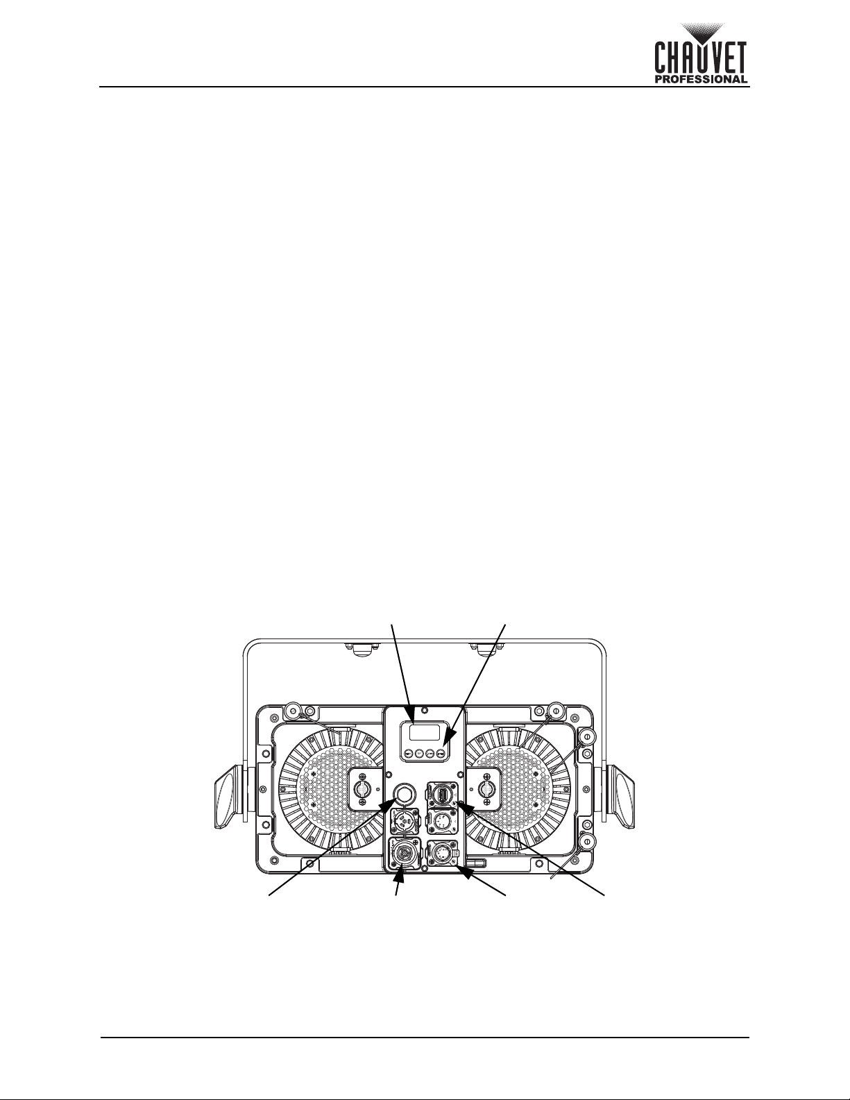
Menu buttonsOLED display
Power in/out DMX in/out USB port
Ventilation valve
2. Introduction
Description
The Strike Array 2 is an outdoor-ready audience blinder powered by two 100 W warm white LEDs housed
in independently focusable pods. An emulated “amber shift” warms the color temperature of the light as it
dims to deliver a classic tungsten look. Its variable PWM and high CRI make it ideal for broadcast
applications. Thanks to a custom interlocking system, the Strike Array 2 can be interconnected with
multiple Array units for scalable design configurations without any tools. Omega-Bracket locks are also
installed both on the yoke and the back of the IP65 blinder to give a streamlined truss mounting process.
Features
• Operating modes:
• 1 Ch (1-channel): Dimmer
• 2 Ch (2-channel): White mode LED1, white mode LED2
• 3 Ch (3-channel): Dimmer, red shift, dimmer speed mode
• 4 Ch (4-channel): White mode LED1, white mode LED2, red shift, dimmer speed mode
• 5 Ch (5-channel): Dimmer, red shift, strobe, auto programs, dimmer speed mode
• 8 Ch (8-channel): Dimmer, 16-bit dimmer, red shift, strobe, white mode LED1, white mode
LED2, auto programs, dimmer speed mode
• Intense 2 pod blinder/strobe rated IP65 for all-weather use
• Emulated “red shift” to mimic incandescent fixtures perfectly.
• Individual pan (or tilt, depending on mount orientation) of each head to allow for directional
adjustment of light output.
• Innovative interlocking system to connect multiple Strike Array 2s and Strike Array 4s together.
• Multiple mounting locations with ¼ turn adaptors for creative and convenient rigging options
• 16-bit dimming control for smooth, perfect fades
• Strobe functionality for high-impact effects on the fly
• Easy to use OLED display
• Adjustable Pulse Width Modulation (PWM) and RDM (Remote Device Management) for added
flexibility
Product Overview
Strike Array 2 User Manual Rev. 2
Page 3 of 18
Page 8
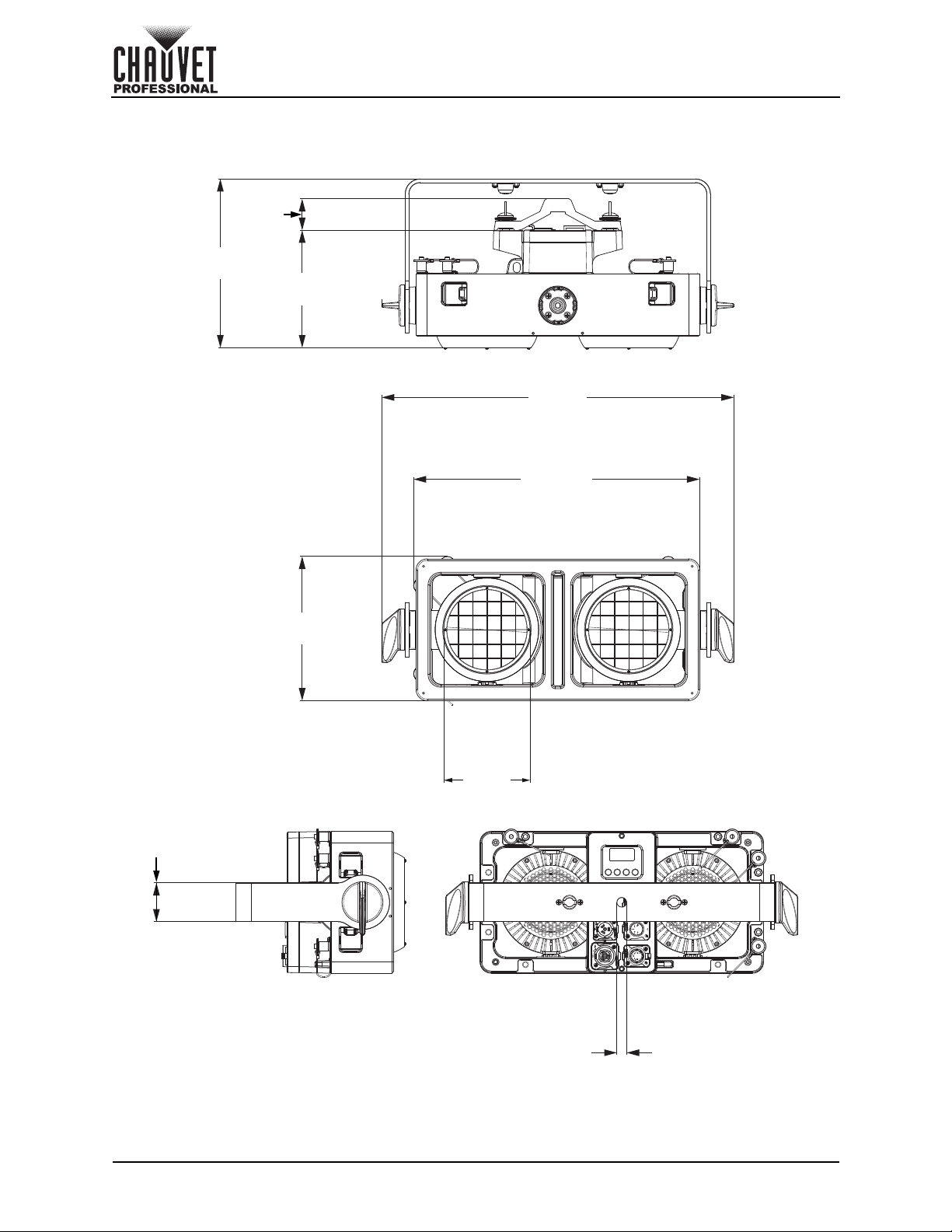
Product Dimensions
1.65 in
42 mm
0.51 in
13 mm
2.05 in
52 mm
8.89 in
225.8 mm
6.42 in
163 mm
7.61 in
193.3 mm
18.58 in
472 mm
15.09 in
383.3 mm
4.55 in
115.6 mm
Introduction
Page 4 of 18
Strike Array 2 User Manual Rev. 2
Page 9
Setup
3. Setup
AC Power
The Strike Array 2 has an auto-ranging power supply and it can work with an input voltage range of 100 to
240 VAC, 50/60 Hz.
To determine the product’s power requirements (circuit breaker, power outlet, and wiring), use the current
value listed on the label affixed to the product’s back panel, or refer to the product’s specifications chart.
The listed current rating indicates the product’s average current draw under normal conditions.
• Always connect the product to a protected circuit (a circuit breaker or fuse). Make sure
the product has an appropriate electrical ground to avoid the risk of electrocution or
fire.
• To eliminate unnecessary wear and improve its lifespan, during periods of non-use
completely disconnect the product from power via breaker or by unplugging it.
Never connect the product to a rheostat (variable resistor) or dimmer circuit, even if the
rheostat or dimmer channel serves only as a 0 to 100% switch.
AC Plug
The Strike Array 2 comes with a power input cord terminated with a Seetronic Powerkon A connector on
one end and an Edison plug on the other end (U.S. market). If the power input cord that came with your
product has no plug, or if you need to change the plug, use the table below to wire the new plug.
Connection Wire (U.S.) Wire (Europe) Screw Color
AC Live Black Brown Yellow or Brass
AC Neutral White Blue Silver
AC Ground Green/Yellow Green/Yellow Green
Power Linking
The product supports power linking. You can power link up to 11 products at 100 V, up to 13 products at
120 V, up to 22 products at 208 V, up to 24 products at 230 V, or up to 25 products at 240 V.
This product comes with a power input cord. Power linking cables are available from Chauvet for
purchase.
Remote Device Management (RDM)
Remote Device Management, or RDM, is a standard for allowing DMX-enabled devices to communicate
bi-directionally along existing DMX cabling. Check the DMX controller’s User Manual or with the
manufacturer as not all DMX controllers have this capability. The Strike Array 2 supports RDM protocol that
allows feedback to make changes to menu map options.
USB Software Update
The Strike Array 2 allows for software updates with a USB device using the built-in USB port. To update the
software using a USB flash drive, do the following:
1. Power on the product, and plug the flash drive into the USB port.
2. Once the flash drive has been detected, the message “Upgrade Firmware” will be displayed.
Press <ENTER>.
• If a different message appears on the display, search for the updated software in the Main Menu
(Update Firmware) and select from Only This Unit, Multiple Units, or Other Fixture Type. A
list of the updated software files will be displayed.
3. Select the file that needs to be uploaded. The message “Are you sure?” will be displayed. Press
<ENTER>.
4. If the selected file is correct, the upgrade will be completed. Restart the product.
• If the selected file is incorrect, the upgrade will fail, and the display will go back to the main
interface. Repeat steps 1-3 using the correct file.
The .chl format file needs to be placed in the “STRIKE” folder in the USB flash drive.
The “Other Fixture Type” option can only be selected for connected products compatible
with the Upload 03 (the first 2 digits of the item code must be 03).
Strike Array 2 User Manual Rev. 2
Page 5 of 18
Page 10
Setup
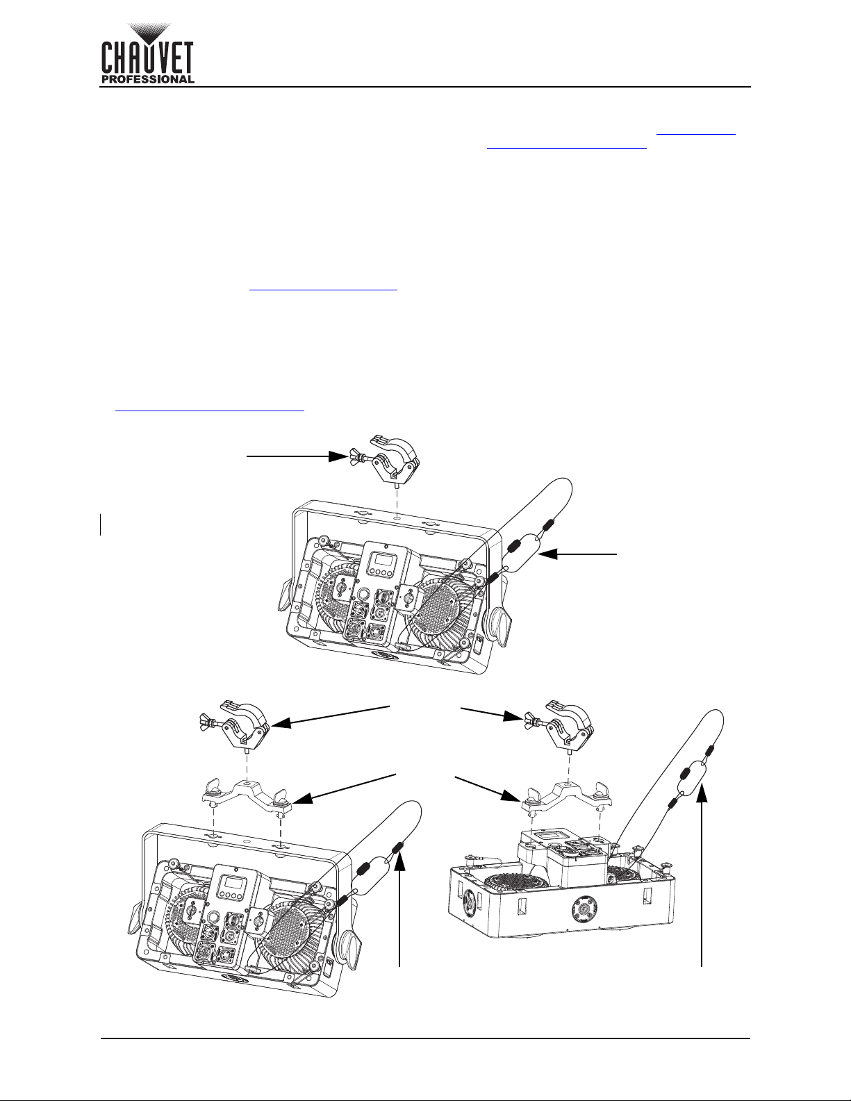
Safety cable
Mounting clamp
Mounting
clamp
Safety
cable
Omega
bracket
Safety
cable
Mounting
Before mounting the product, read and follow the safety recommendations indicated in the Safety Notes.
For our CHAUVET Professional line of mounting clamps, go to http://trusst.com/products/
Orientation
Always mount this product in a safe position, making sure there is adequate room for ventilation,
configuration, and maintenance.
Rigging
Chauvet recommends using the following general guidelines when mounting this product.
• Before deciding on a location for the product, make sure there is easy access to the product for
maintenance and programming purposes.
• Make sure that the structure onto which you are mounting the product can support the product’s
weight. See the Technical Specifications
• When mounting the product overhead, always use a safety cable. Mount the product securely to a
rigging point, whether an elevated platform or a truss.
• When rigging the product onto a truss, use a mounting clamp of appropriate weight capacity.
for weight information.
Procedure
The Strike Array 2 comes with a bracket to which you can attach a mounting clamp directly. Mounting
clamps are sold separately. Make sure the clamps are capable of supporting the weight of this product.
Use at least two mounting points per product. For the CHAUVET Professional line of mounting clamps, go
to http://www.trusst.com/products
Product Mounting Diagram
.
.
Page 6 of 18
Strike Array 2 User Manual Rev. 2
Page 11
Setup
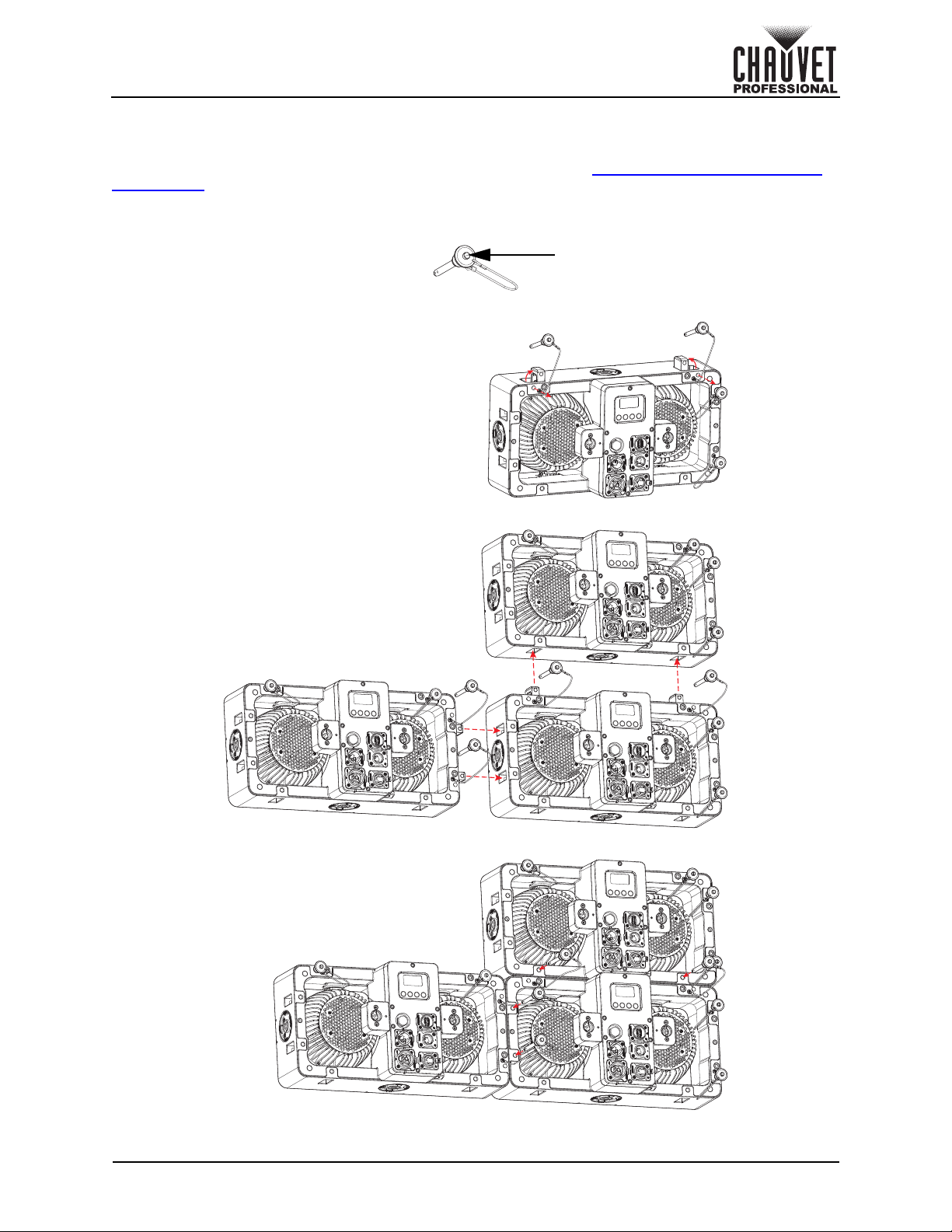
Remove the retaining pins
to release the integrated
hanging hardware
Insert the retaining
pins to lock the
products together
Insert the integrated
hanging hardware into the
opening of the next product
(vertically or horizontally)
Press and hold the latch
button to remove or
insert the retaining pins
Latch button
Multi-Product Mounting
The Strike Array 2 has an interlocking system to connect multiple Strike Array 2 or STRIKE Array 4
products together, vertically or horizontally. Make sure the mounting clamps are capable of supporting the
weight of the product. For our Chauvet line of mounting clamps, go to http://trusst.com/productcategory/
truss-clamps/.
Multi-Product Mounting Diagram
Strike Array 2 User Manual Rev. 2
Page 7 of 18
Page 12
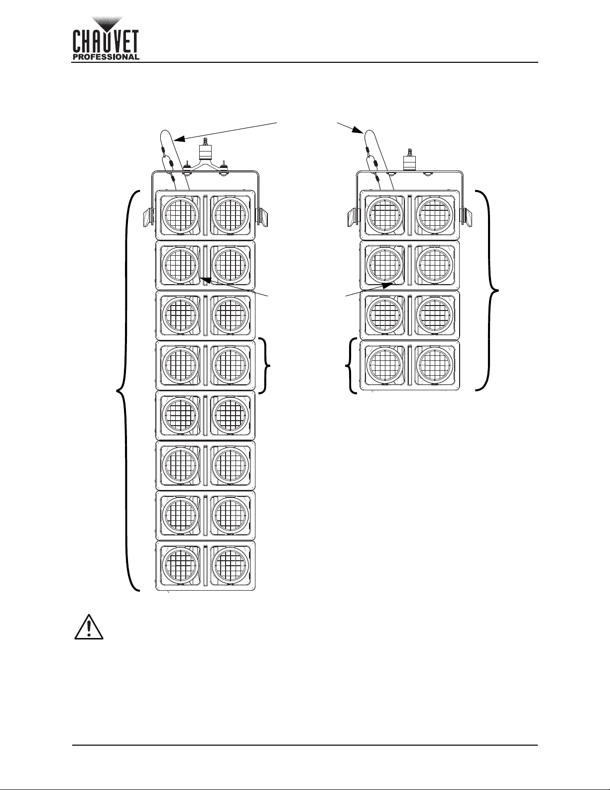
Mounting Products Attached in Series
With Omega Bracket Without Omega Bracket
Attach the
safety cable
of the first
product to the
mounting
point
Attach the
safety cables
of the following
products to the
preceding
product
Each
Strike Array 2
product is 2
cells
Up to
16 cells
Up to
8 cells
Setup
• When using the omega bracket, never hang more than 16 cells vertically from a single
• When not using the omega bracket, never hang more than 8 cells vertically from a single
Page 8 of 18
mounting point.
mounting point.
Strike Array 2 User Manual Rev. 2
Page 13
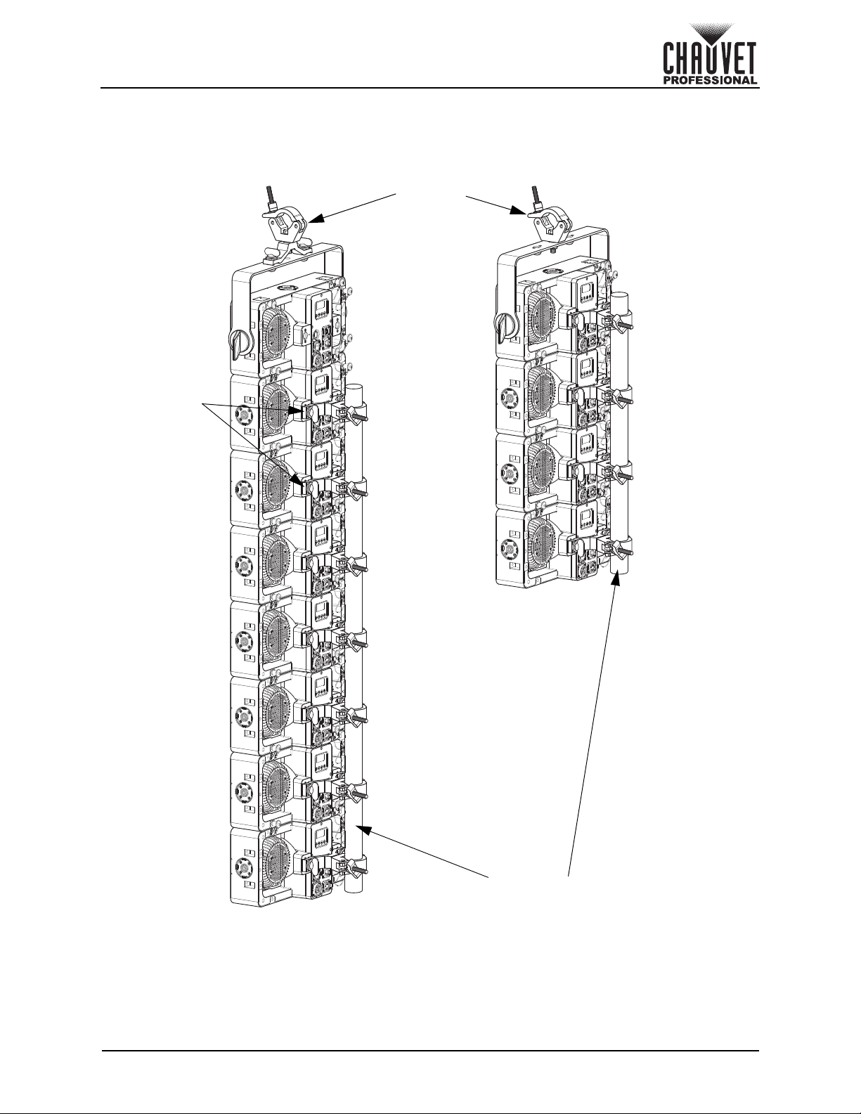
Omega
brackets
Mounting
clamps
Pole or pipe
for stability
Setup
Vertical Mounting Stability
When mounting products attached in series, use omega brackets in the back position to create a spine.
This will prevent any motion which may damage the products.
Strike Array 2 User Manual Rev. 2
Page 9 of 18
Page 14
Operation
4. Operation
Control Panel Description
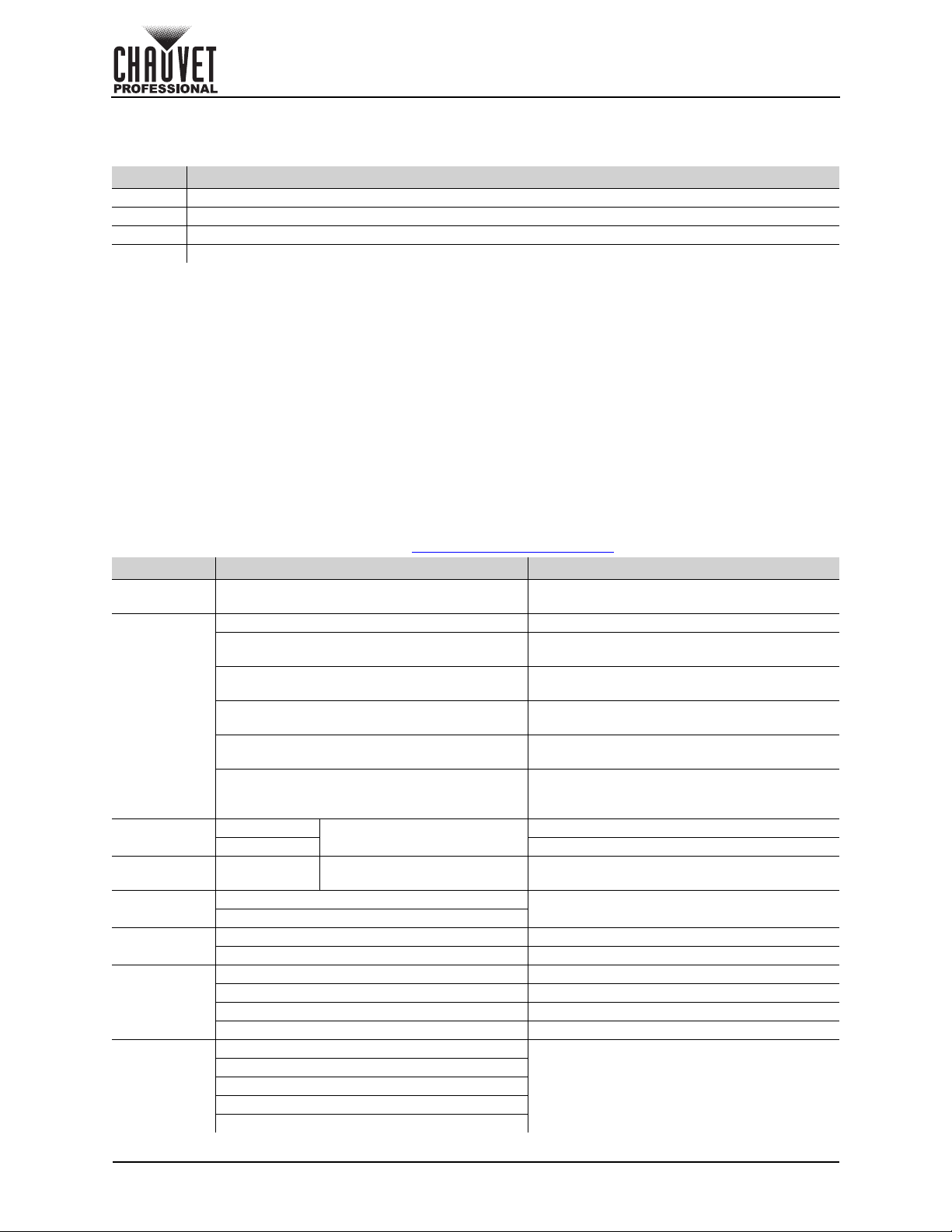
Button Function
<MENU> Exits from the current menu or function
<UP> Enables the selected menu or sets the selected value in to the current function
<DOWN> Navigates upward through the menu list or increases the numeric value when in a function
<ENTER>
Control Options
Set the Strike Array 2 starting address in the 001–512 DMX range. This enables control of up to 64
products in the 8-channel 8 Ch personality.
Programming
Refer to the Menu Map to understand the menu options. The menu map shows the main level and a
variable number of programming levels for each option.
• To go to the desired main level, press <MENU> repeatedly until the option shows on the display.
• To select an option or value within the current programming level, press <UP> or <DOWN> until the
• Press <MENU> repeatedly to exit to the previous main level.
Passcode
After being prompted to enter the passcode, press <UP>, <DOWN>, <UP>, <DOWN>, <ENTER>.
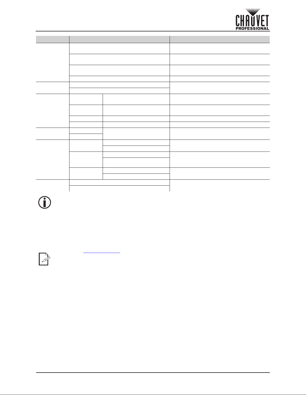
Menu Map
Refer to the Strike Array 2 product page on
Main Level Programming Levels Description
Start Address 001–512*
DMX Channel
Auto Show Auto 1–6 Speed 001–100
Red Shift
Master/Slave
Dimmer
Frequency
Navigates downward through the menu list or decreases the numeric value when in a function
Press <ENTER> to select. This will take you to the first programming level for that option.
option shows on the display. Press <ENTER> to select. In this case, if there is another programming
level, you will see that first option, or you will see the selected value.
Static
Mode
LED
Dimmer
Strobe
www.chauvetprofessional.com
Selects starting address (*highest channel
restricted to personality chosen)
1 Ch 1-channel: Dimmer
2 Ch
3 Ch
4 Ch
5 Ch
8 Ch
000–255
On
Off
Master Master mode
Slave Slave mode
Off Linear dimmer
Dimmer 1 Fast dimmer curve
Dimmer 2 Medium dimmer curve
Dimmer 3 Slow dimmer curve
600Hz
1200Hz
2000Hz
4000Hz
25KHz
2-channel: White mode LED1, white mode
LED2
3-channel: Dimmer, red shift, dimmer speed
mode
4-channel: White mode LED1, white mode
LED2, red shift, dimmer speed mode
5-channel: Dimmer, red shift, strobe, auto
programs, dimmer speed mode
8-channel: Dimmer, 16-bit dimmer, red shift,
strobe, white mode LED1, white mode LED2,
auto programs, dimmer speed mode
Sets the intensity of the output
Selects the strobe frequency
Selects automatic programs and auto
program speed
Enables/disables red shift (amber LEDs
imitate lamp when dimming)
Selects the PWM output frequency
for the latest menu map.
Page 10 of 18
Strike Array 2 User Manual Rev. 2
Page 15
Operation
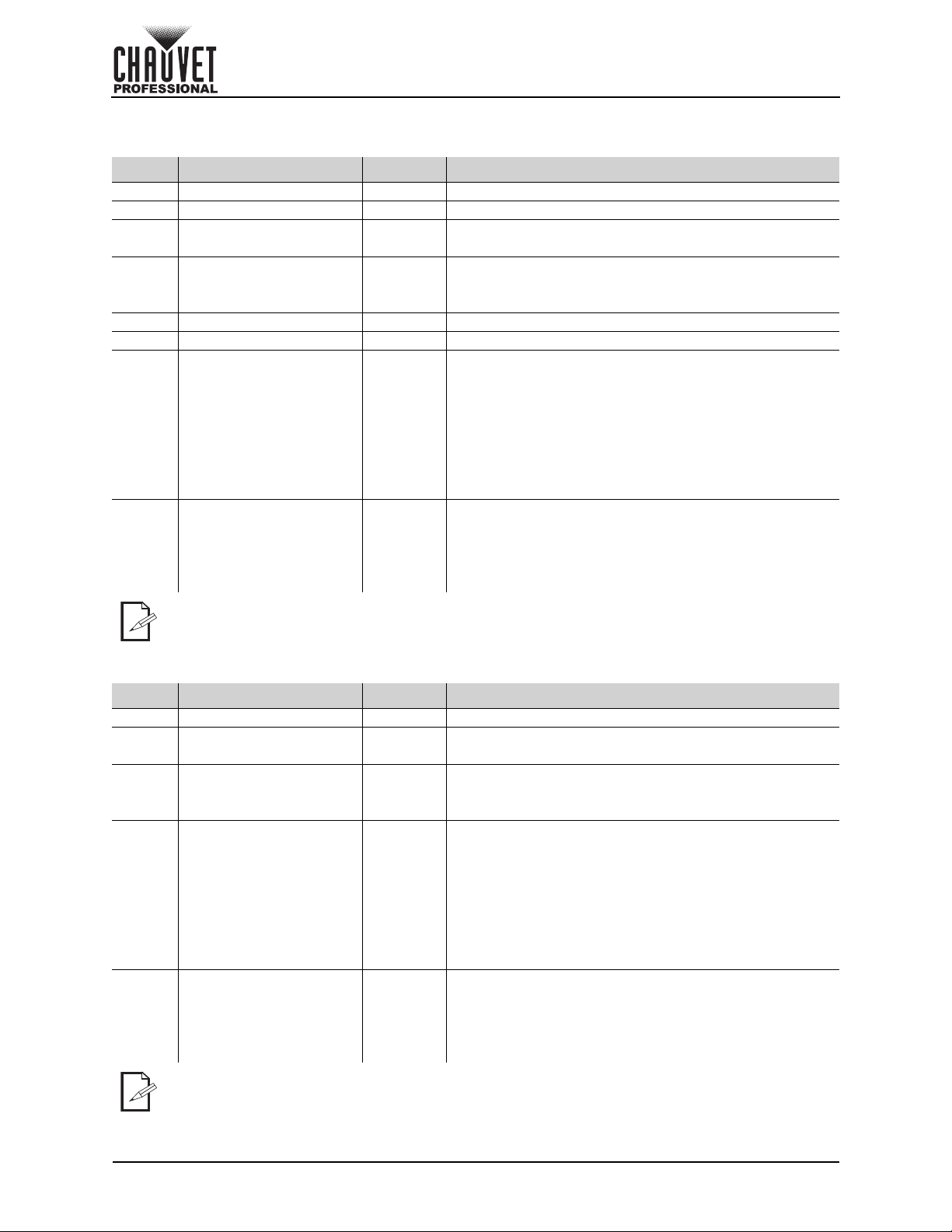
Main Level Programming Levels Description
Turns off display backlight after 10 seconds
of inactivity
Turns off display backlight after 30 seconds
of inactivity
Turns off display backlight after 2 minutes of
inactivity
Locks display (password: <UP>, <DOWN>,
<UP>, <DOWN>, <ENTER>)
Shows total hours the product has been
powered on
Shows the total hours the LED lights have
been on
Selects an update file for this product, or
shows “No such file!”
Strike Array 2 products, or shows “No such
file!”
Selects an update file for other connected
products, or shows “No such file!”
Reset to factory defaults
Back Light
Key Lock
Information
Temperatur e
Update
Firmware
Factory
Reset
10S
30S
2Min
Always On Display backlight always on
On
Off
Fixture Hours _ _ _ H
LED Hours _ _ _ H
Version V_._ Shows installed software version
UID _ _ _ _ _ _ _ _ _ _ _ _ Shows product UID
LED1:
LED2:
Only This
Unit
Multiple
Units
Other Fixture
Type
_ _°C Individual pod temperature
_ _ _ _ _ _.CHL
...
_ _ _ _ _ _.CHL Selects an update file for this and connected
...
_ _ _ _ _ _.CHL
...
No
Yes
The “Other Fixture Type” option under Update Firmware can only be selected for
connected products compatible with the Upload 03 (the first 2 digits of the item code must
be 03).
Configuration (DMX)
Use control configurations to operate the product with a DMX controller.
Control Personalities
To set the control personality:
1. Go to the DMX Channel main level.
2. Select the desired personality, from 1 Ch, 2 Ch, 3 Ch, 4 Ch, 5 Ch, 8 Ch.
• See the Starting Address
personality.
• Make sure that the starting addresses on the various products do not overlap due to the new
personality setting.
Starting Address
Each product will respond to a unique starting address from the controller. All products with the same
starting address will respond in unison. To set the starting address:
1. Go to the Start Address main level.
2. Select the starting address (1–512).
• The highest recommended starting address for 1 Ch is 512.
• The highest recommended starting address for 2 Ch is 510.
• The highest recommended starting address for 3 Ch is 509.
• The highest recommended starting address for 4 Ch is 508.
• The highest recommended starting address for 5 Ch is 507.
• The highest recommended starting address for 8 Ch is 505.
section for the highest starting address you can select for each
Strike Array 2 User Manual Rev. 2
Page 11 of 18
Page 16
Control Channel Assignments and Values
8 Ch
Channel Function Value Percent/Setting
1 Dimmer 000 255 0–100%
2 Dimmer Fine 000 255 0–100%
3Red Shift
4Strobe
5White 1 000 255 0–100%
6White 2 000 255 0–100%
7 Auto Programs
8 Dimmer Speed Mode*
000 000 On
001 255 Off
000 010 No function
011 132 Strobe, slow to fast (all pods)
133 255 Strobe, slow to fast (random strobe macros)
000 010 No function
011 040 Auto 1 (slow to fast)
041 080 Auto 2 (slow to fast)
081 120 Auto 3 (slow to fast)
121 160 Auto 4 (slow to fast)
161 200 Auto 5 (slow to fast)
201 240 Auto 6 (slow to fast)
241 255 No function
000 051 Current dimmer speed mode
052 101 Dimmer speed mode off (linear dimmer)
102 152 Dimmer speed mode 1 (fastest)
153 203 Dimmer speed mode 2
204 255 Dimmer speed mode 3 (slowest)
Operation
*Hold desired dimmer speed value for 3 seconds, then release. This changes the dimmer
speed setting in the menu.
5 Ch
Channel Function Value Percent/Setting
1 Dimmer 000 255 0–100%
2Red Shift
3Strobe
4 Auto Programs
5 Dimmer Speed Mode*
000 000 On
001 255 Off
000 010 No function
011 132 Strobe, slow to fast (all pods)
133 255 Strobe, slow to fast (random strobe macros)
000 010 No function
011 040 Auto 1 (slow to fast)
041 080 Auto 2 (slow to fast)
081 120 Auto 3 (slow to fast)
121 160 Auto 4 (slow to fast)
161 200 Auto 5 (slow to fast)
201 240 Auto 6 (slow to fast)
241 255 No function
000 051 Current dimmer speed mode
052 101 Dimmer speed mode off (linear dimmer)
102 152 Dimmer speed mode 1 (fastest)
153 203 Dimmer speed mode 2
204 255 Dimmer speed mode 3 (slowest)
*Hold desired dimmer speed value for 3 seconds, then release. This changes the dimmer
speed setting in the menu.
Page 12 of 18
Strike Array 2 User Manual Rev. 2
Page 17
Operation
4 Ch
Channel Function Value Percent/Setting
1White 1 000 255 0–100%
2White 2 000 255 0–100%
3Red Shift
4 Dimmer Speed Mode*
*Hold desired dimmer speed value for 3 seconds, then release. This changes the dimmer
speed setting in the menu.
3 Ch
Channel Function Value Percent/Setting
1 Dimmer 000 255 0–100%
2Red Shift
3 Dimmer Speed Mode*
000 000 On
001 255 Off
000 051 Current dimmer speed mode
052 101 Dimmer speed mode off (linear dimmer)
102 152 Dimmer speed mode 1 (fastest)
153 203 Dimmer speed mode 2
204 255 Dimmer speed mode 3 (slowest)
000 000 On
001 255 Off
000 051 Current dimmer speed mode
052 101 Dimmer speed mode off (linear dimmer)
102 152 Dimmer speed mode 1 (fastest)
153 203 Dimmer speed mode 2
204 255 Dimmer speed mode 3 (slowest)
*Hold desired dimmer speed value for 3 seconds, then release. This changes the dimmer
speed setting in the menu.
2 Ch
Channel Function Value Percent/Setting
1White 1 000 255 0–100%
2White 2 000 255 0–100%
1 Ch
Channel Function Value Percent/Setting
1 Dimmer 000 255 0–100%
Strike Array 2 User Manual Rev. 2
Page 13 of 18
Page 18

Operation
Configuration (Standalone)
Static Color
To run the Strike Array 2 on a static setting:
1. Go to the Static main level.
2. Select from Dimmer or Strobe.
3. Increase or decrease the value from 000–255.
Automatic Program
To run an automatic program:
1. Go to the Auto Show main level.
2. Select from Auto 1–6.
3. Increase or decrease the Spreed from 001–100.
Configuration (Settings)
Red Shift
With red shift enabled, the amber LEDs will dim on an inverse curve to imitate a lamp. To enable or disable
the red shift function:
1. Go to the Red Shift main level.
2. Select from On or Off.
Master Slave
To set the Strike Array 2 product to master or slave mode:
1. Go to the Master/Slave main level.
2. Select from Master (sends control signal) or Slave (receives control signal).
• Configure all the slave products before connecting the master to the daisy chain.
• Never connect a DMX controller to a DMX string configured for Master/Slave operation
because the controller may interfere with the signals from the master.
• Do not connect more than 31 slaves to the master.
Dimmer Mode
To select the dimmer mode:
1. Go to the Dimmer Mode main level.
2. Select from Off (linear dimmer) or Dimmer 1–3 (fast to slow).
Pulse Width Modulation
To set the PWM frequency:
1. Go to the LED Frequency main level.
2. Select from 600Hz, 1200Hz, 2000Hz, 4000Hz, or 25KHz.
Display Back Light
To select how long a period of inactivity before the display automatically turns off:
1. Go to the Back Light main level.
2. Select from 10S (10 seconds), 30S (30 seconds), 2Min (2 minutes), or Always On.
Key Lock
To lock or unlock the control panel:
1. Go to the Settings main level.
2. Select the Key Lock option.
3. Select On (locks control panel) or Off (control panel stays unlocked).
When the key lock is activated, the product will prompt for the passcode in order to access
the menu. The passcode is <UP>, <DOWN>, <UP>, <DOWN>, <ENTER>.
Product Information
To view the product information, go to the Information main level.
Temperature
To view the temperature (in °C) of the LED pods, go to the Temperature main level.
Factory Reset
To reset the product to factory default settings:
1. Go to the Factory Reset main level.
2. Select from No (cancel) or Yes (reset).
Page 14 of 18
Strike Array 2 User Manual Rev. 2
Page 19

Maintenance
5. Maintenance
Product Maintenance
Dust build-up reduces light output performance and can cause overheating. This can lead to reduction of
the light source’s life and/or mechanical wear. To maintain optimum performance and minimize wear, clean
your lighting products at least twice a month. However, be aware that usage and environmental conditions
could be contributing factors to increase the cleaning frequency.
To clean the product, follow the instructions below:
1. Unplug the product from power.
2. Wait until the product is at room temperature.
3. Use a vacuum (or dry compressed air) and a soft brush to remove dust collected on the external
surface/vents.
4. Clean all transparent surfaces with a mild soap solution, ammonia-free glass cleaner, or isopropyl
alcohol.
5. Apply the solution directly to a soft, lint free cotton cloth or a lens cleaning tissue.
6. Softly drag any dirt or grime to the outside of the transparent surface.
7. Gently polish the transparent surfaces until they are free of haze and lint.
Always dry the transparent surfaces carefully after cleaning them.
Strike Array 2 User Manual Rev. 2
Page 15 of 18
Page 20
Technical Specifications
UL 1573
CSA C22.2 No. 166
E113093
R
6. Technical Specifications
Dimensions and Weight
Length Width Height Weight
18.5 in (469 mm) 10.4 in (264.5 mm) 6.3 in (161 mm) 17.6 lb (8.0 kg)
Note: Dimensions in inches are rounded.
Power
Power Supply Type Range Voltage Selection
Switching (internal) 100 to 240 VAC, 50/60 Hz Auto-ranging
Parameter 100 V, 60 Hz 120 V, 60 Hz 208 V, 60 Hz 230 V, 50 Hz 240 V, 50 Hz
Consumption 124 W 123 W 127 W 129 W 130 W
Operating
Current
Power linking
current
(products)
Power I/O U.S./Worldwide UK/Europe
Power Input Connector Seetronic Powerkon IP65 Seetronic Powerkon IP65
Power Output Connector Seetronic Powerkon IP65 Seetronic Powerkon IP65
Power Cord plug Edison (U.S.) Local Plug
Light Source
Type Color Quantity Power Current Lifespan
LED Warm white 96 1.33 W 0.852 A 50,000 hours
LED Amber 10 1.92 W 0.652 A 50,000 hours
Photometrics
Beam Angle Field Angle Illuminance @ 5 m
60.3° 99° 360 lux
Thermal
Ambient Temperature Range Cooling System
-4 °F to 113 °F (-20 °C to 45 °C) Convection
DMX
Ordering
Product Name Item Name Item Code UPC Number
Strike Array 2
1.24 A1.04 A0.61 A0.56 A0.54 A
13.6 A (11
products)
13.6 A (13
products)
13.6 A (22
products)
13.6 A (24
products)
13.6 A (25
products)
I/O Connector Channel Range
5-pin XLR 1, 2, 3, 4, 5, or 8
STRIKEARRAY2
03051713 78146220617
Page 16 of 18
Strike Array 2 User Manual Rev. 2
Page 21
Returns
Returns
Send the product prepaid, in the original box, and with the original packing and accessories. Chauvet will
not issue call tags.
Call Chauvet and request a Return Merchandise Authorization (RMA) number before shipping the product.
Be prepared to provide the model number, serial number, and a brief description of the cause(s) for the
return.
To submit a service request online, go to www.chauvetprofessional.com/service-request
Clearly label the package with an RMA number. Chauvet will refuse any product returned without an RMA
number.
Write the RMA number on a properly affixed label. DO NOT write the RMA number directly
on the box.
Before sending the product, clearly write the following information on a piece of paper and place it inside
the box:
• Your name
• Your address
• Your phone number
• RMA number
• A brief description of the problem
Be sure to pack the product properly. Any shipping damage resulting from inadequate packaging will be
your responsibility. FedEx packing or double-boxing are recommended.
Chauvet reserves the right to use its own discretion to repair or replace returned
product(s).
.
Strike Array 2 User Manual Rev. 2
Page 17 of 18
Page 22
Contact Us
Chauvet World Headquarters
Chauvet Europe Ltd
Chauvet Europe BVBA
Chauvet France
Chauvet Germany
Chauvet Mexico
Address: Av. de las Partidas 34 - 3B
Lerma, Edo. de México, CP 52000
General Information Technical Support
Address: 5200 NW 108th Ave. Voice: (844) 393-7575
Sunrise, FL 33351 Fax: (954) 756-8015
Voice: (954) 577-4455 Email: [email protected]
Fax: (954) 929-5560
Toll Free: (800) 762-1084 Website: www.chauvetprofessional.com
Address: Unit 1C Email: [email protected]
Brookhill Road Industrial Estate
Pinxton, Nottingham, UK Website: www.chauvetprofessional.eu
NG16 6NT
Voice: +44 ( 0 ) 1 7 7 3 51111 5
Fax : + 4 4 ( 0 ) 1 773 511110
Address: Stokstraat 18 Email: [email protected]
9770 Kruishoutem
Belgium Website: www.chauvetprofessional.eu
Voice: +32 9 388 93 97
Address: 3, Rue Ampère
91380 Chilly-Mazarin
France Website: www.chauvetprofessional.eu
Voice: +33 1 78 85 33 59
Address: Bruno-Bürgel-Str. 11
28759 Bremen
Germany Website: www.chauvetprofessional.eu
Voice: +49 421 62 60 20
(Entrance by Calle 2)
Zona Industrial Lerma Website: www.chauvetprofessional.mx
Voice: +52 (728) 690-2010
Email: [email protected]
Email: [email protected]
Email: [email protected]
Contact Us
Visit the applicable website above to verify our contact information and instructions to request support.
Outside the U.S., U.K., Ireland, Benelux, France, Germany, or Mexico, contact the dealer of record.
Page 18 of 18
Strike Array 2 User Manual Rev. 2
 Loading...