

Page 1
T E C HN IC A L R E F E R E N C E & M A N U AL
LEGEND 250RX
DMX-1655R
3000 North 29th Ct.
Hollyw ood, FL 33020
Tel: 954-929-1115 Fax: 954-929-5560
CHAUVET
www.CHAUVETlighting.com
Page 2

Table of Contents
Table of Contents
Table of ContentsTable of Contents
WARRANTY INFORMATION..........................................................................................................3
INTRODUCTION................................................................................................................................4
Safety Instructions....................................................................................................................................4
Caution.............................................................................................................................................4
Technical Specifications ............................................................................................................................5
Product Overview.....................................................................................................................................6
What is enclosed......................................................................................................................................6
BEFORE YOU BEGIN......................................................................................................................7
Unpacking Instructions..............................................................................................................................7
Mounting................................................................................................................................................7
Powering................................................................................................................................................7
OPERATING INSTRUCTIONS........................................................................................................8
Control panel overview..............................................................................................................................8
Display panel diagram...............................................................................................................................9
DMX-512 addressing ..............................................................................................................................10
Stand alone (master/slave) operation ..........................................................................................................10
Slave & 2 Light Show operation .......................................................................................................... 11
Color presets .........................................................................................................................................11
Pan invert ............................................................................................................................................. 11
Tilt invert..............................................................................................................................................12
LCD reverse display ...............................................................................................................................12
Focus adjustment....................................................................................................................................12
Self test mode........................................................................................................................................ 12
Fixture life counter .................................................................................................................................13
Fixture reset .......................................................................................................................................... 13
Control Panel Reset...........................................................................................................................13
DMX Reset......................................................................................................................................13
CA-8 Easy Controller..............................................................................................................................13
DMX-512 attributes................................................................................................................................14
Pre-programmed shows ...........................................................................................................................15
Channel 14 ...................................................................................................................................... 15
Channel 15 ...................................................................................................................................... 15
DMX-512 connection.............................................................................................................................. 16
Inserting/Exchanging rotating gobos ..........................................................................................................17
Lamp replacement .................................................................................................................................. 17
APPENDIX ........................................................................................................................................18
Maintenance.......................................................................................................................................... 18
DMX Primer.........................................................................................................................................18
Returns Procedure .................................................................................................................................. 18
Claims..................................................................................................................................................18
Fixture Cleaning.....................................................................................................................................18
General Troubleshooting.......................................................................................................................... 19
DMX-1655 Manual Version 1.11 2222
Issue Date: December 2003
Rev. No. Version Date Description
0 1.11 Jan 2004 DMX- 1655 Users Guide version 1.10: Revised: V.M. at CHAUVET
Page 3
Warranty Information
We take great pride in the quality, value and performance of our products and believe that it should offer
you trouble free operation throughout its lifetime providing you take care to follow the simple instructions
in this manual.
a) CHAUVET provides, from the date of purchase, to the original purchaser, a 24-month limited warranty on all DMX products, a
12-month limited warranty on special effect fixtures and controllers and a 3-month limited warranty on items with an “NV”
prefi x. This limited warranty covers manufacturing defects i n material and wor kmanship only. At the time of service, the owner
will need to be able to provide evidence of date and place of purchase and serial number.
b) CHAUVET does not cover damage or failure caused by abuse, misuse, faulty installation, improper maintenance, or any
repairs not carried out by CHAUVET.
c) Items which are not covered by warranty are those considered as parts which are prone to failure due to general wear and
tear. For example – lamps, fuses, brushes and belts. Laser diodes carry a (90day) warranty. For foggers, see user manual.
d) There will be no obligations or liability on the part of CHAUVET for consequential damages arising from the use of the product
or any indirect damages with respect to l oss of property, revenue, or costs for removal, installation, or re-installation.
e) For warranty service the pr oduct must be reported to CHAUVET to receive a unique RA# (returns authorization number) and at
that time you will be advised of where to send the faulty product.
f) All shipping charges for returns should be pre-paid. If the requested repairs or service are within the terms of this warranty then
the item will be returned to you on completi on without any charge. The unit must be in its original packaging with any original
accessories. CHAUVET will not be responsible or accept any liabilities for any loss or damage to additional items which are
sent with returned product.
g) If this product is not covered under the terms of this warranty, CHAUVET will advise you of the costs to carry out any repairs
necessary and the unit will be shipped to you on receipt of payment for the work including the return freight charges.
h) Please allow 2 to 4 weeks for return of your product. Under normal circumstances we try to ensure we carry out warranty
repairs within 5 working days. We cannot be held responsible for delays in shipping.
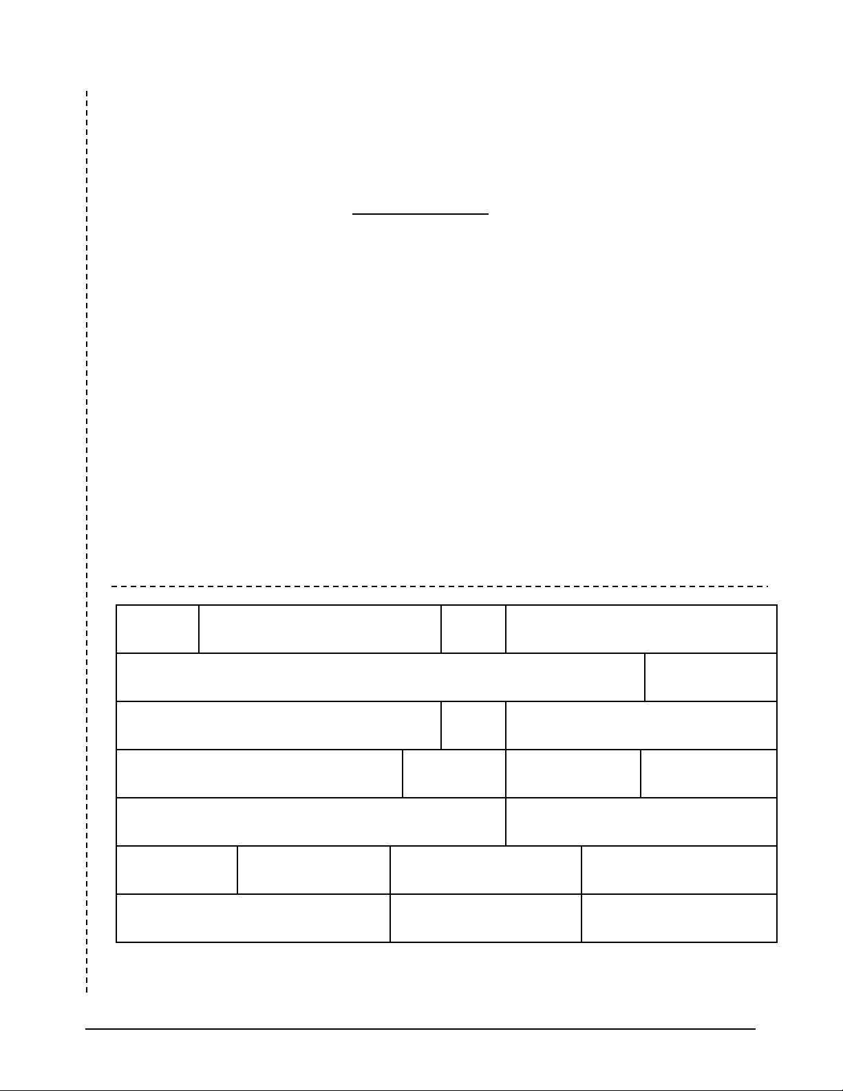
LIMITED WARRANTY USA
Title First Name Initials Last Name
Address Apt.
City State Or Province
Country Zip Code Or Postal Code Date of Birth
e-mail Telephone # (include ar ea code)
Date of Purchase
Dealer City Country
Purchase Price
(before tax) Model Serial #
CHAUVET U.S.A.
Warranty Registration
3000 North 29
DMX-1655 Manual Version 1.11 3333
th
Ct.
Page 4

Introduction
Please read these instructions carefully, which includes important
Safety Instructions
information about the installation, usage and maintenance?
Please keep this User Guide for future consultation. If you sell the unit to another user, be sure that they also receive this
instruction booklet.
Alw ays make sure that you are connecting to the proper voltage and that the line voltage you are connecting to is not higher
than that stated on decal or rear panel of the fixture.
This product is intended for indoor use only!
To prevent risk of fire or shock, do not expose fixture to rain or moisture. Make sure there are no flammable materials close
to the unit while operating.
The unit must be installed in a location with adequate ventilation, at least 50cm from adjacent surfaces. Be sure that no
ventilation slots are blocked.
Alw ays disconnect from power source before servicing or replacing lamp or fuse and be sure to replace w ith same lamp
source.
Secure fixture to fastening device using a safety chain. Never carry the fixture solely by its head. Use its carrying handles.
Maximum ambient temperature is Ta: 40℃. Do not operate fixture at temperatures higher than this.
In the event of serious operating problem, stop using the unit immediately. Never try to repair the unit by yourself. Repairs
carried out by unskilled people can lead to damage or malfunction. Please contact the nearest authorized technical assistance
center. Always use the same type spare parts.
Don’t connect the device to a dimmer pack.
Make sure power cord is never crimped or damaged.
Never disconnect pow er cord by pulling or tugging on the cord.
Avoid direct eye exposure to lamp. Gas discharge lamps generate UV radiation. Never operate the lamp without
appropriate protection as it could damage skin and eyes. These lamps operate at high pressures and there is always a slight
risk of tube rupture. The risk of rupture increases with age, temperature and improper handling of the lamp. These lamps
also generate UV radiation. The UV radiation that is emitted extends well below 287nm, which is considered the point at
which the UV radiation becomes imminently harmful. Exposure to this short wave UV should be limited. If aligning a
lamp, care must be taken to reduce the exposure time to the lamp. Never look directly at any lamp while it is powered on.
Read the booklet that accompanies each lamp and heed attention to the warnings concerning exposure to skin and eyes.
Use appropriate eye protection to block all UV rays. Do not use ordinary sunglasses.
Caution
There are no user serviceable parts inside the unit. Do not open the housing
or attempt any repairs yourself. In the unlikely event your unit may require
service, please contact your nearest dealer.
DMX-1655 Manual Version 1.11 4444
Page 5
I N T R O D U C T I O N
Channel
Function
Channel
Function
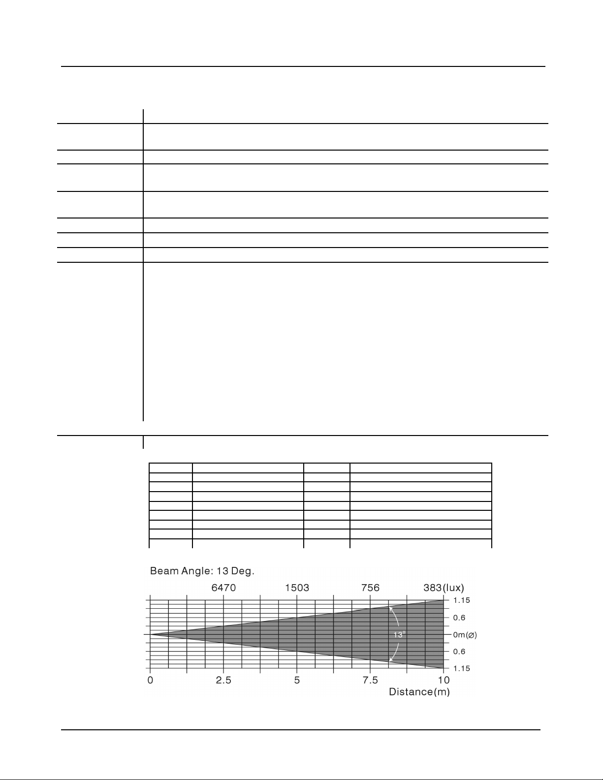
Technical Specifications
Power AC 120V~60Hz or 230V/240V/250V 50/60Hz
Lamp Discharge lamp MSD 250W GY9.5
CHAUVET Model No. US-HSD250 or CH-MSD250
Dimensions 14.2in x 15.6in x 19.8in / 360mm x 397mm x 503mm
Shipping 57.2 Lbs / 26 Kg
Master Packed 1pc/57.2 Lbs
Control DMX-512 via XLR 3-Pin Connectors, IN & OUT
Operates on 16 Channels of DMX
Optical System
Pan
Tilt
Features 7 interchangeable rotating gobos plus open
Warranty 2 Year Limited Warranty
DMX Channels
Projection
Standard 13° focused beam angle
540° in 2.8 seconds
270° in 1.6 seconds
4 metal gobos
2 glass gobos
1 effect gobo
3 extra metal gobos
2 extra effect gobos
Gobo wheel rotates with variable speed and rainbow effect
Independent color wheel with 9 dichroic lens filters plus white
Color wheel rotates with variable speed and rainbow effect
Prism: 3-facet prism rotates in both directions at variable speeds
Blackout, Independent 0-100% smooth dimming and strobe speed variable
(1~10 flashes per second)
1 Pan Movement 9 Gobos
2 Tilt Movement 10 Gobo Rotation
3 Pan/Tilt Speed select 11 Prism
4 Dimmer 12 Prism Rotation
5 Shutter/Shaking 13 Focus
6 Color 14 Pre-programmed Show Pattern
7 Reserved 15 Pre-programmed Beam Pattern
8 Reset 16 Reset
DMX-1655 Manual Version 1.11 5555
Page 6
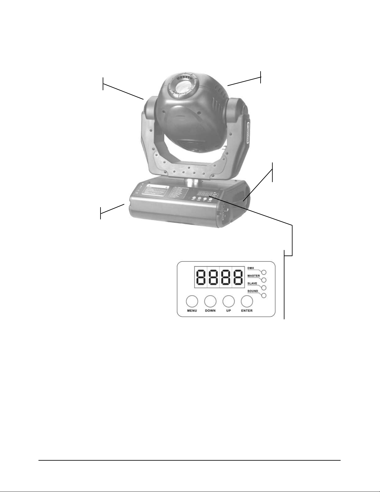
Product Overview
Head
Yoke
Base
Carrying
Control Display
handles
What is enclosed
Manual / Warranty Card
DMX-1655 Legend 250RX
Pow er cord with plug (affixed to device)
Mounting bracket w ith knobs
Lamp: MSD250 250w
DMX-1655 Manual Version 1.11 6666
Page 7

Before you Begin
Unpacking Instructions
Immediately upon receiving a fixture, carefully unpack the carton, check the contents to ensure that all parts are present, and have
been received in good condition. Notify the shipper immediately and retain packing material for inspection if any parts appear
damaged from shipping or the carton itself shows signs of mishandling. Save the carton and all packing materials. In the event that a
fixture must be returned to the factory, it is important that the fixture be returned in the original factory box and packing.
Mounting
The unit should be mounted via its mounting system
( as show n to the right ) on the bottom of the base.
Use clamps to fix the unit to truss. Alw ays ensure that
the unit is firmly fixed to avoid vibration and slipping
while operating. Always ensure that the structure to
which you are attaching the unit is secure and is able
to support a w eight of 30 kgs for each unit.
This fixture may be mounted in any position
provided there is adequate room for ventilation. It is
important never to obstruct the fan or vents pathway.
Mount the fixture using, preferably the center
mounting holes and a suitable “C” or “O” type
clamp. Adjust the angle of the fixture by loosening
both knobs and tilting the fixture. After finding the
desired position, retighten both knobs. When
selecting installation location, take into consideration
lamp replacement access and routine maintenance.
Safety cables should always be used. Never mount in
places where the fixture w ill be exposed to rain, high
humidity, extreme temperature changes or restricted
ventilation.
Powering
To determine the pow er requirements for a particular fixture, see the label affixed to the back plate of the fixture or refer to the
fixture’s specifications chart. A fixture’s listed current rating is its average current draw under normal conditions. All fixtures must be
pow ered directly off a sw itched circuit and cannot be run off a rheostat (variable resistor) or dimmer circuit, even if the rheostat or
dimmer channel is used solely for a 0% to 100% sw itch. Before applying power to a fixture, check that the source voltage matches the
fixture’s requirement. All fixtures must be connected to circuits with a suitable Earth Ground. Check the fixture or device carefully to
make sure that if a voltage selection switch exists that it is set to the correct line voltage you will use.
DMX-1655 Manual Version 1.11 7777
Page 8

Operating Instructions
Control panel overview
Display LED Indicators
DMX
MASTER
SLAVE
SOUND
Control Buttons
MENU
DOWN
UP
ENTER
Rear Panel
DMX OUT/IN
MIC
SENSITIVITY
REMOTE
CONTROL
On DMX input is present
On Master mode
On Slave mode
Flashing Sound Activation
Selects programming functions
Moves backward in selected functions
Moves forw ard in selected functions
Confirms selected function
DMX-512 connectors, Use 3-pin XLR cables
Built in microphone for sound-to-light operation
Audio sensitivity adjustment
Accepts ¼” connector from the “CA-8 Easy Controller” providin g
Stand By, Strobe/Next and Show 1 1/Slow /Show 2 functions.
DMX-1655 Manual Version 1.11 8888
Page 9

Display panel diagram
To select any of the pre-set functions, press the MENU button until the desired function is shown on the display. Select the function
by pressing the ENTER button and the display will blink. Use the DOWN and UP button to change the settings. Once the
required setting has been selected, press the ENTER button to activate it. If you don not press the ENTER button, it will
automatically return to the main functions without any change after idling 8 seconds. To go back to the functions w ithout any change
press the MENU button. The main functions are shown below:
DMX-1655 Manual Version 1.11 9999
Page 10

DMX-512 addressing
This mode enables the use of a universal DMX controller device. Each fixture requires a "start address" from 1 to 511. A fixture
requiring one or more channels for control begins to read the data on the channel indicated by the start address. For example, a
fixture that occupies or uses 6 channels of DMX and was addressed to start on DMX channel 100, would read data from channels:
100, 101, 102, 103, 104, and 105. Choose start addresses so that the channels used do not overlap and notate the start address selected
for future reference. The Legend 250RX operates using 16 channels of DMX control.
If this is your first time addressing a fixture using the DMX-512 control protocol than I suggest jumping to the Appendix Section and
read the heading “DMX Primer”. It contains very useful information that will help you understand its use.
Upon pow ering up the unit, you will notice that it will display “AE16”. In addition, the fixtures electronics will load up its
programming and home (adjust) its motors to a starting position. The sequence of events should take no more than 20 seconds and it
is necessary for the fixture to operate correctly. During this time you will hear motor and mechanical movement inside the fixture.
After this initial power-up sequence, if the fixture receives no DMX signal, it w ill enter into a stand alone mode. Be sure to power up
your DMX controller device before the lighting fixture to avoid unwanted auto mode operation.
1. Press the MENU button until the display reads- .
2. Press the ENTER button to select DMX addressing. The selection is confirmed
when begins to blink. You must make a selection within 8 seconds.
3. Press the UP and DOWN buttons to increase or decrease values until the desired
value is achieved.
4. Press the ENTER button to activate selection.
Example Diagram: First 4 fixtures assigned.
NOTE! It is not necessary to turn the unit off when changing the DMX address.
Stand alone (master/slave) operation
By linking the units under a master/slave control mode, the first unit can direct additional units to create a sound activated,
synchronized light show. This is very useful for mobile DJs who want to setup and run a show quickly.
In this mode the fixture is assigned a master status and is indicated by the MASTER LED.
If the fixture is not connected to a controller then it will automatically enter a sound
activated state. You can adjust the mic sensitivity pod on the fixture for optimum sound
recognition.
1. Press the MENU button until the display reads- .
2. Press the ENTER button to select Show Mode. The selection is confirmed when
begins to blink. You must make a selection w ithin 8 seconds.
3. Press the UP and DOWN buttons to toggle betw een the 2 pre-programmed show
modes in the fixture. Show 1 - and Show 2 -
4. Press the ENTER button to activate selection.
Typical use for Show 1 would be when fixture is placed on the floor. The tilt will move up
to an angle of 210°.
Typical use for Show 2 would be when fixture is hung from the ceiling or flow n on a truss.
The tilt w ill move up to an angle of 90°.
DMX-1655 Manual Version 1.11 10
10
1010
Page 11

NOTE! Chauvet’s CA-8 Easy Controller offers a simple, yet effective means of selecting various other
automatic program functions not directly available through the control panel. Please read the area
labeled “CA-8 Easy Controller”
NOTE! Slave mode can only be assigned w hen the fixture is presently connected to other fixtures.
Color presets
Slave & 2 Light Show operation
1. Press the MENU button until the display reads- .
2. Press the ENTER button to select Slave Mode. The selection is confirmed when
begins to blink. You must make a selection w ithin 8 seconds.
3. Press the UP and DOWN buttons to toggle betw een the 2 slave modes.
4. Press the ENTER button to activate selection.
(Normal) Synchronized movement of the fixture.
(2 Light Show ) Pan & tilt will be inverted on this fixture. All other programs w ill execute in
sync.
The Legend 250RX provides 2 color preset modes. This affects the way you call colors on
the slider on a DMX controller.
1. Press the MENU button until the display reads- .
2. Press the ENTER button to select Color Mode. The selection is confirmed when
begins to blink. You must make a selection w ithin 8 seconds.
3. Press the UP and DOWN buttons to toggle betw een the 2 Color Modes, Normal
and Split Colors .
4. Press the ENTER button to activate selection.
Pan invert
Normal color mode provides indexed color presets. Only solid colors will appear as you
move the channel fader on a controller.
Split color mode provides indexed solid and split color presets. Both w ill appear as you
move the channel fader on a controller.
NOTE! A color scrolling preset exists in both modes. This is when the color wheel begins to rotate
continuously and you can select the rate of speed, for a rainbow color like affect.
1. Press the MENU button until the display reads- .
2. Press the ENTER button to select Pan Invert. The selection is confirmed when
begins to blink. You must make a selection w ithin 8 seconds.
3. Press the UP and DOWN buttons to toggle betw een Normal and
Inverted .
4. Press the ENTER button to activate selection.
Normal pan movement
Pan movement inverted
DMX-1655 Manual Version 1.11 11
11
1111
Page 12

Tilt invert
Normal tilt movement
Tilt movement inverted
LCD reverse display
Normal display orientation
Orientation reversed
1. Press the MENU button until the display reads- .
2. Press the ENTER button to select Tilt Invert. The selection is confirmed w hen
begins to blink. You must make a selection w ithin 8 seconds.
3. Press the UP and DOWN buttons to toggle betw een Normal and
Inverted .
4. Press the ENTER button to activate selection.
1. Press the MENU button until the display reads- .
2. Press the ENTER button to reverse the display. The selection is confirmed when
the display begins to blink. You must make a selection within 8 seconds.
3. Follow step # 2 again to return the display to normal.
Focus adjustment
Focus adjustment enables the user to set a lens focus on any of 5 specific focus points (x/y
axis positioning). Manual focus adjustment is available in Stand-alone only.
Self test mode
1. Press the MENU button until the display reads- .
2. Press the ENTER button and the fixture will automatically move to the first
position which is straight up or Tilt/90°. The display also begins to blink. There are
5 selectable positions in total: Tilt/90°, Pan/0°, Pan/90°, Pan/180° & Pan/270°.
Pressing ENTER button will advance the head to the next position. Leave in the
desired position and follow the next step.
3. At this point you can manually adjust the focus by pressing the UP and DOWN
buttons. The display will read numbers 1 through 255.
4. Press the MENU button to store this setting.
1. Press the MENU button until the display reads- .
2. Press the ENTER button and the fixture will run through various self-test
programs.
3. Press the MENU button to return to the main menu.
DMX-1655 Manual Version 1.11 12
12
1212
Page 13

Fixture life counter
Fixture reset
Control Panel Reset
DMX Reset
1. Press the MENU button until the display reads- .
2. Press the ENTER button and the display will read the number of hours the
fixture has been in operation.
3. Press the MENU button to return to the main menu or leave for 5 seconds and
fixture will return to the normal display.
1. Press the MENU button until the display reads- .
2. Press the ENTER button to reset the fixture. All motors and mechanical parts will
return to the initial pow er-up positions.
Fixture
Channel Level
8 255
16 240
Figure 3.10-1
1. On your DMX controller device set the follow ing DMX level outputs shown in “Figure
3.10-1”
2. The fixture will reset when both of the fixture channels shown in “Figure 3.10-1”
receive the specified levels.
CA-8 Easy Controller (Optional)
The easy remote controller is used only in master/slave mode. By connecting the 1/4”
microphone jack to the first unit, you w ill find that the remote control on the first unit will
control all the other units for Stand by, Strobe/Next/Strobe and Show 1/Slow /Show 2
functions.
Buttons Function
STAND BY Will blackout all units connected
FUNCTION or
STROBE/NEXT
In Show 1 Tap: Steps through color and gobo presets
Hold: Will strobe in w hite
In Slow Tap: Every 10 taps steps through each color and
In Show 2 Tap: Steps through color and gobo presets
Hold: Will strobe in w hite
the 11th tap changes the gobo. Repeat as necessary
to achieve desired result.
FAST/SLOW
NO TE! All movement and changes are sound activated except when in
DMX-1655 Manual Version 1.11 13
LED Status Mode
Off Show 1 (210° Tilt)
On Slow Show 1 (Slow motion)
Blinking Show 2 (90° Tilt)
SLOW Show 1 mode. In SLOW mode, color and gobo change is
user selectable using the “CA-8 Easy Controller”.
13
1313
Page 14

DMX-512 attributes
Reserved for
DMX-1655 Manual Version 1.11 14
14
1414
Page 15

The Legend 250RX
includes the following
extra gobos shown
here on the right!
Pre-programmed shows
Channel 14
All other control except pre-programs on channel 15 becomes inactive.
Channel 15
pattern programs can also be selected.
DMX-1655 Manual Version 1.11 15
- As illustrated above, beginning on values 32 the stand alone shows are user selectable while in DMX control mode.
– As illustrated above and in tandem with the selection of a pre-programmed show on channel 14 various beam
15
1515
Page 16

DMX-512 connection
If you use a controller with a 5 pin DMX output connector, you will need to use a 5 to 3 pin adapter. Chauvet Model No: DMX5M
The last unit on the DMX chain should be terminated with a terminator. Solder a 120-ohm 1/4W resistor betw een pin 2(DMX-) and
pin 3(DMX+) into a 3-pin XLR-plug and plug it in the DMX-output of the last unit.
Connect the units together in a “daisy chain” fashion by connecting an XLR plug from the output of the unit to the input of the next
unit. The cable cannot be branched or split to a “Y” cable. DMX512 contains a high-speed signal. Inadequate or damaged cables,
soldered joints or corroded connectors can easily distort the signal and shut down the system.
Each lighting unit needs to have an address set to receive the data sent by the controller. Fixtures are addressable between 1 and 512.
Refer to Section 3.3 DMX addressing for further instructions.
XLR Configuration:
3 pin XLR: Pin 1: GND, Pin 2: Negative signal (-), Pin 3: Positive signal (+)
5 pin XLR: Pin 1: GND, Pin 2: Negative signal (-), Pin 3: Positive signal (+)
DMX-1655 Manual Version 1.11 16
16
1616
Page 17

Inserting/Exchanging rotating gobos
When replacing lamp, please wait 15 minutes after
CAUTION!
CAUTION!
Open the cover by loosening the fastening
screw at the sides of the cover. Remove
the “O” ring with tw eezers if available,
insert the new gobo and replace the “O”
ring.
Never unscrew the screws of the
rotating gobo as the ball bearing will
otherw ise be opened!
Sw itch off device before
exchanging gobos or colors.
Lamp replacement
powering down to allow the unit cool down!
Because of its high internal pressure, there might be a risk that the Discharge lamp
could explode during operation. The lamp emits intense UV radiation which is
harmful to the eyes and skin. The high luminance of the arc can cause severe
damage to the retina if you look directly into the lamp source.
Alw ays switch off the main supply and never handle the lamp or luminaries w hen
it is hot.
Do not touch the bulb with bare hands. If this happens, clean the lamp with
alcohol and w ipe it with a lint free cloth before installation.
The lamp generates UV radiation. Never operate the lamp without appropriate
shielding.
When burning, the lamp operates at high pressure and there is a slight risk of arc
tube rupture. The risk increases w ith age, temperature and improper handling of
the lamp. Do not use the lamp any longer than its specified life.
Make sure the lamp is located in the
center of the reflector for the best spot.
Adjust lamp position by screws A, B
and C.
DMX-1655 Manual Version 1.11 17
A
C
B
17
1717
Page 18

Appendix
Maintenance
To maintain optimum performance and minimize wear fixtures should be cleaned frequently. Usage and environment are
contributing factors in determining frequency. As a general rule, fixtures should be cleaned at least twice a month. Dust build up
reduces light output performance and can cause overheating. This can lead to reduced lamp life and increased mechanical wear. Be
sure to power off fixture before conducting maintenance.
Unplug fixture from power. Use a vacuum or air compressor and a soft brush to remove dust collected on external vents and internal
components. Clean all glass w hen the fixture is cold with a mild solution of glass cleaner or Isopropyl Alcohol and a soft lint free
cotton cloth or lens tissue. Apply solution to the cloth or tissue and drag dirt and grime to the outside of the lens. Gently polish
optical surfaces until they are free of haze and lint. Do not to touch the lamp glass when cleaning fixture. Oil and dirt can cause
damage and premature aging of the lamp. In the event that the lamp is touched or becomes dirty, clean the lamps with an alcohol
wipe.
DMX Primer
There are 512 channels in a DMX-512 connection. Channels may be assigned in any manner. A fixture capable of receiving DMX
512 will require one or a number of sequential channels. The user must assign a starting address on the fixture that indicates the first
channel reserved in the controller. There are many different types of DMX controllable fixtures and they all may vary in the total
number of channels required. Choosing a start address should be planned in advance. Channels should never overlap. If they do, this
will result in erratic operation of the fixtures whose starting address is set incorrectly. You can however, control multiple fixtures of
the same type using the same starting address as long as the intended result is that of unison movement or operation. In other words,
the fixtures will be slaved together and all respond exactly the same.
DMX fixtures are designed to receive data through a serial Daisy Chain. A Daisy Chain connection is w here the DATA OUT of one
fixture connects to the DATA IN of the next fixture. The order in w hich the fixtures are connected is not important and has no
effect on how a controller communicates to each fixture. Use an order that provides for the easiest and most direct cabling. Connect
fixtures using shielded tw o conductor tw isted pair cable with three pin XLR male to female connectors. The shield connection is pin
1, while pin 2 is Data Negative (S-) and pin 3 is Data positive (S+). CHAUVET carries 3-pin XLR DMX compliant cables, DMX-10
(33’), DMX-4.5 (15’) and DMX-1.5 (5’)
Returns Procedure
Returned merchandise must be sent prepaid and in the original packing, call tags will not be issued. Package must be clearly labeled
with a Return Merchandise Authorization Number (RA #). Products returned without an RA # will be refused. Call CHAUVET and
request RA # prior to shipping the fixture. Be prepared to provide the model number, serial number and a brief description of the
cause for the return. Be sure to properly pack fixture, any shipping damage resulting from inadequate packaging is the customer’s
responsibility. CHAUVET reserves the right to use its own discretion to repair or replace product(s). As a suggestion, proper UPS
packing or double-boxing is alw ays a safe method to use.
Claims
Damage incurred in shipping is the responsibility of the shipper; therefore the damage must be reported to the carrier upon receipt of
merchandise. It is the customer's responsibility to notify and submit claims w ith the shipper in the event that a fixture is damaged due
to shipping. Any other claim for items such as missing component/part, damage not related to shipping, and concealed damage,
must be made within seven (7) days of receiving merchandise.
Fixture Cleaning
The cleaning of internal and external optical lenses and/or mirrors must be carried out periodically to optimize light output. Cleaning
frequency depends on the environment in which the fixture operates: damp, smoky or particularly dirty surrounding can cause greater
accumulation of dirt on the unit’s optics.
Clean with soft cloth u sing normal glass cleaning fluid. - Always dry the parts carefully. - Clean the external optics at least every 20 days.
Clean the internal optics at least every 30/60 days.
DMX-1655 Manual Version 1.11 18
18
1818
Page 19

General Troubleshooting
Symptom Solution(s)
Fixture has no pow er Check for pow er on Mains.
Check fixture’s fuse.
Lamps cuts off sporadically Possible bad lamp or fixture is overheating. Check the fan. Lamp may be at end of its
life.
Motor movements are jerky or
jumpy
Beam is very dim Clean optical system or replace lamp.
Fixture is on but there is no
movement to the audio
Fixture does not respond to DMX
Some units do not respond to the
Easy Controller
Does not respond to sound 1. Check the unit that is not receiving DMX signal.
A channel is not w orking w ell 1. The stepper motor might be damaged or the cable connected to the PCB is
If pan belt is broken
1. Turn off the main pow er.
2. Unscrew all the screw s (A) and open
the base-housing cover (B).
3. Unplug all the connect w ires (C)
from the arm to PC board and
igniter.
4. Unscrew (D) screws to release
bridge (E).
5. Unscrew the (F) screw s that connect
the axis gear (G).
6. Change a new belt (H) by going
through all connect ing w ires from
the base, and through the bridge to
the correct position.
7. Set the gear axis back to the bridge
and screw it. Note: do not press the
belt.
8. Put the belt around the axis gear and
motor gear.
9. Plug all the connect w ires (C) that
form the arm to PC board and
igniter.
10. Adjust the pan home position.
11. Screw the base-housing cover (B).
Possible bad motor driver or sensors.
Adjust the audio sensitivity pod.
1. DMX LED should be on. If it is not, check the DMX connector and cables for
proper contact.
2. If the DMX LED is on and does not respond to the channel, check the address
settings and DMX polarity.
3. If you have intermittent DMX signal problems, check the pins on connectors or
on PCB of the unit or the previous one.
4. Use another DMX controller to rule out controller issues.
5. Check if the DMX cables run near or run alongside high voltage cables that may
cause damage or interference to DMX interface circuit.
6. Wrong DMX address in the unit. Set the proper address.
1. You may have a break in the DMX cabling. Check the LED for the response of
the master/ slave mode signal.
2. Check microphone to see if it is good by tapping the microphone
broken.
2. The motor’s drive IC on the PCB might be out of condition.
DMX-1655 Manual Version 1.11 19
19
1919
 Loading...