

Page 1
Wireless Professional
User Manual EN
Page 2
QUICK START GUIDE
EN
WIRELESS PROFESSIONAL
Note
- It is strongly advised to carefully read the contraindications and safety measures described in
chapter 1 and 2 in this manual before using your device.
- For detailed information on usage also see Chapters 3 to 14 of this manual.
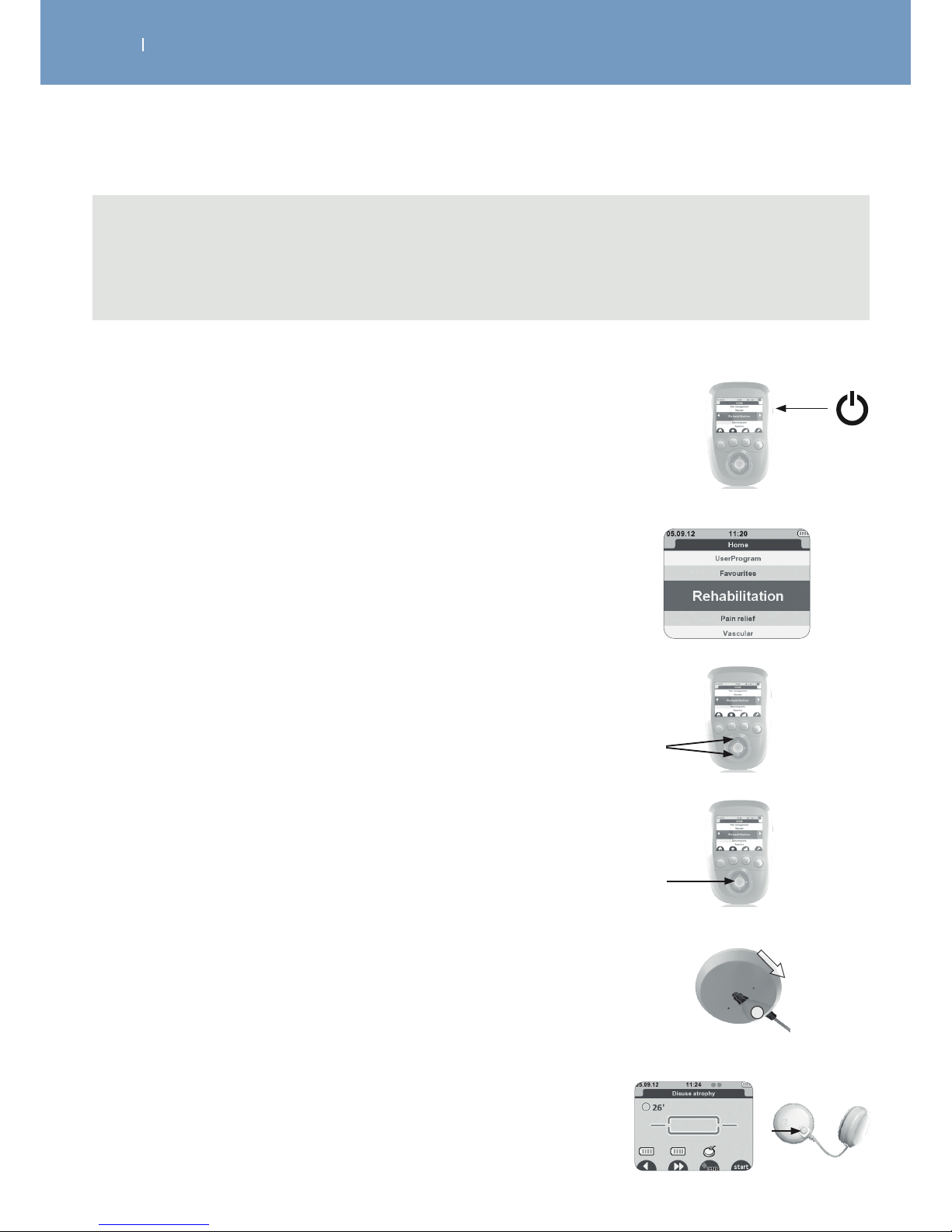
1. Turn the Remote Control on, by pressing the On/
Off button.
2. Upon activation the screen displays a list that
gives you access to the categories of programmes.
3. Select a program category and a program within
the category by using the navigation pad
(up/down)
4. Confirm your choice with the centre button.
5. Stick the electrodes on the patient and connect
the modules.
6. Turn on the modules, being careful to respect the
order of activation of the modules, the turning-on
order corresponds to the channel numbering.
Page 3
QUICK START GUIDE
EN
WIRELESS PROFESSIONAL
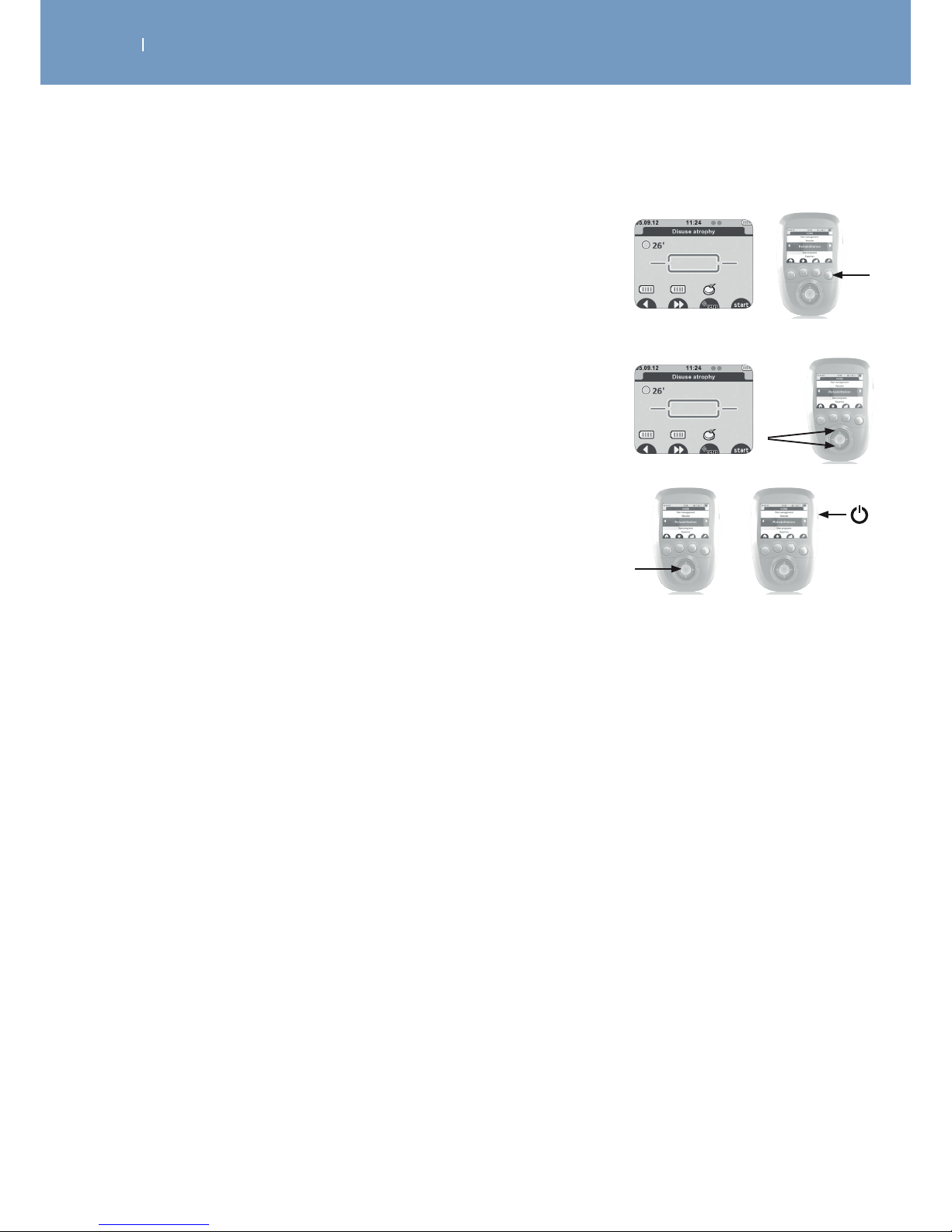
7. Validate everything by pressing the button below
the START symbol.
If the mi-SCAN function is activated, a short sequence of
measures is performed. Throughout the duration of the test,
it is important to stay still and be perfectly relaxed. When the
test is complete, the programme can begin.
8. Start the stimulation by increasing the energies of
the channels.
To pause the device, press the centre button.
9. At the end of the programme press the centre
button to return to the main menu or press the
On/Off button to turn off the device.
Page 4

CONTENTS
EN
WIRELESS PROFESSIONAL
1. How to Use the Medical Equipment (Intended Use) .......................................................................................... 7
1.1 Fields of application ..............................................................................................................................................................................7
1.2 Therapy objectives ................................................................................................................................................................................7
1.3 Indications .................................................................................................................................................................................................8
1.4 Contraindications ..................................................................................................................................................................................8
1.5 Secondary eects ................................................................................................................................................................................. 9
2. Safety Information ....................................................................................................................................................10
3. Description of the Wireless Professional ............................................................................................................. 18
3.1 Device components and accessories .......................................................................................................................................... 18
3.2 Explanation of symbols (connections and nameplates) ..................................................................................................20
3.2.1 Symbols on device and AC Power Supply ............................................................................................................................20
3.2.2 Symbols on Charging Tablet/Docking Station and AC Power Supply ....................................................................22
3.3 Description of the device components .................................................................................................................................... 24
3.3.1 Remote Control ...............................................................................................................................................................................24
3.3.2 Modules ............................................................................................................................................................................................... 25
3.4 Description of key accessories .....................................................................................................................................................26
3.4.1 Smart 4CH docking station and Removeable tablet ..................................................................................................... 26
3.4.2 Basic 2 CH docking station ........................................................................................................................................................27
3.4.3 The Motor Point Pen .................................................................................................................................................................... 28
3.5 Description of key Displays shown ............................................................................................................................................ 29
3.5.1 Display in Programme Category selection mode (Home Screen) ............................................................................ 29
3.5.2 Display in Programme selection mode ................................................................................................................................30
3.5.3 Diplay when programm is selected, Modules need to be turned on, mode ........................................................ 31
3.5.4 Display during treatment ............................................................................................................................................................32
3.5.5 Display during pause in treatment ..........................................................................................................................................33
3.5.6 Display at the end of a treatment .......................................................................................................................................... 34
4. Device Setup...............................................................................................................................................................35
4.1 Smart 4CH Docking station - Connecting the unit, performance check ..................................................................35
4.2 Charging the Remote Control and the Modules ...............................................................................................................36
4.3 Multi-Sessions mode – Synchronisation with few remotes and Smart 4CH Docking station .................... 38
4.4 Basic 2CH Docking station - Connecting the unit, performance check ................................................................. 39
5. How to Perform a Treatment, Performance Check ........................................................................................40
5.1 Select a Program ............................................................................................................................................................................... 40
5.2 Adjust treatment options ................................................................................................................................................................ 41
5.3 Electrode placement .........................................................................................................................................................................41
5.4 Body positioning of the patient .................................................................................................................................................. 42
5.5 Connecting the modules to the electrodes ........................................................................................................................... 43
5.6 Starting the treatment ....................................................................................................................................................................44
Page 5

CONTENTS
EN
WIRELESS PROFESSIONAL
5.7 Ending the treatment ......................................................................................................................................................................46
5.8 Performance Check .......................................................................................................................................................................... 46
6. Treatment Options, Functions and Device Settings ........................................................................................47
6.1 How to use the Motor Point Pen ............................................................................................................................................... 47
6.2 Treatment Options – Muscle Intelligence™ Technology ................................................................................................49
6.2.1 Selection of the body area ..........................................................................................................................................................49
6.2.2 Energy management ...................................................................................................................................................................50
6.2.3 Triggering of contraction ............................................................................................................................................................. 51
6.3 Available Functions ............................................................................................................................................................................53
6.3.1 The Favorite List ...............................................................................................................................................................................53
6.3.2 The Lock Out function ................................................................................................................................................................. 54
6.3.3 The Synchronisation Signal ........................................................................................................................................................56
6.3.4 Identify modules ..............................................................................................................................................................................57
6.4 Available device Settings ................................................................................................................................................................58
6.5 WIRELESS PROFESSIONAL SOFTWARE
(firmware update remote control, customized programs, patient history) ................................................................. 60
6.5.1 Firmware update of the Remote Control ........................................................................................................................... 60
6.5.2 Additional Functions of the SOFTWARE, when having a WIRELESS PROFESSIONAL device ....................61
6.5.2.1 History list ....................................................................................................................................................................................... 62
6.5.2.2 Create a patient’s list and monitor their treatment progress ................................................................................ 63
6.5.2.3 Create customized stimulation programs .......................................................................................................................64
6.5.2.4 Remote Synchronization ......................................................................................................................................................... 67
6.5.2.5 Configuration/Settings ............................................................................................................................................................. 68
6.5.2.6 Help ................................................................................................................................................................................................... 69
7. Troubleshooting .......................................................................................................................................................70
7.1 Errors shown on display ..................................................................................................................................................................70
7.2 Behaviour of the Module LEDs ....................................................................................................................................................73
7.3 Behaviour of the Docking Station LEDs ................................................................................................................................. 74
7.4 Others ......................................................................................................................................................................................................75
8. Care, Maintenance, Transport, Environmental Statement ............................................................................78
8.1 Care .......................................................................................................................................................................................................... 78
8.2 Maintenance ........................................................................................................................................................................................ 79
8.3 Transport .............................................................................................................................................................................................. 80
8.3.1 Transport of the 4CH device key components and the Tablet (o site treatment) ........................................ 80
8.3.2 Shipping the entire 4CH unit (incl. Smart Docking Station) ........................................................................................ 81
8.3.3 Transport of the 2CH device key components .................................................................................................................. 82
8.3.4 Shipping the entire 2CH unit (incl. Basic Docking Station) ......................................................................................... 83
8.4 Enviromental Statement, Expected Life .................................................................................................................................. 84
Page 6

CONTENTS
EN
WIRELESS PROFESSIONAL
9. Technical Data, Standards, Guarantee, Patents ............................................................................................... 85
9.1 Technical Data ..................................................................................................................................................................................... 85
9.1.1 General information ....................................................................................................................................................................... 85
9.1.2 Neuro-Stimulation Parameters ................................................................................................................................................86
9.1.3 RF data .................................................................................................................................................................................................86
9.1.4 Information on electromagnetic compatibility (EMC) ................................................................................................. 87
9.1.5 Enviromental conditions .............................................................................................................................................................. 87
9.2 Standards ..............................................................................................................................................................................................88
9.3 Guarantee ............................................................................................................................................................................................. 88
9.4 Patents ................................................................................................................................................................................................... 88
10. EMC Tables ...............................................................................................................................................................89
10.1 Electromagnetic emissions .......................................................................................................................................................... 89
10.2 Electromagnetic immunity ....................................................................................................................................................... 90
10.3 Recommended separation distances ....................................................................................................................................92
11. Contact ........................................................................................................................................................................93
12.Electrotherapy Theory ............................................................................................................................................ 94
12.1 Introduction .........................................................................................................................................................................................94
12.1.1 The fundamental law of electrostimulation .......................................................................................................................94
12.1.2 Summary ...........................................................................................................................................................................................98
12.1.3 References .........................................................................................................................................................................................99
12.2 The Optimum Current ...................................................................................................................................................................99
12.2.1 Introduction......................................................................................................................................................................................99
12.2.2 Characteristics of the optimal current ................................................................................................................................ 99
12.2.2.1 Electrical stimulation wave produced by the current generator .......................................................................... 99
12.2.2.2 Type of establishment of the electrical stimulation wave ................................................................................... 100
12.2.2.3 Shape of the electrical stimulation wave .......................................................................................................................101
12.2.2.4 Duration of rectangular electrical pulse ....................................................................................................................... 102
12.2.2.5 Compensation for the rectangular pulse ......................................................................................................................104
12.2.3 Summary ......................................................................................................................................................................................... 105
12.3 Basic concepts of excitation electrophysiology ................................................................................................................ 105
12.3.1 Introduction .................................................................................................................................................................................... 105
12.3.2 Study of the excitation process using a constant current ........................................................................................107
12.3.3 Excitation by a current with any shape ............................................................................................................................109
12.3.4 Chronaxy - excitation constant relationship .................................................................................................................109
12.3.5 Hydraulic model of excitation ................................................................................................................................................110
13. Available Therapy Programs ................................................................................................................................112
13.1 Standard Version Programs and their usage ........................................................................................................................112
13.1.1 Program category REHABILITATION I .................................................................................................................................. 113
13.1.2 Program category PAIN RELIEF .............................................................................................................................................122
Page 7

CONTENTS
EN
WIRELESS PROFESSIONAL
13.1.3 Program category VASCULAR .................................................................................................................................................131
13.1.4 CONDITIONING I .........................................................................................................................................................................139
13.2 Full Version Programs and their usage (Indication Specific Programs) ................................................................ 144
13.2.1 REHABILITATION II ..................................................................................................................................................................... 146
13.2.2 AGONIST / ANTAGONIST .......................................................................................................................................................160
13.2.3 PROGRAMMES FOR HAEMOPHILIACS ............................................................................................................................163
13.2.4 NEUROLOGICAL ......................................................................................................................................................................... 166
13.2.5 PAIN RELIEF II ................................................................................................................................................................................174
13.2.6 CONDITIONING II ...................................................................................................................................................................... 190
14. How to Use the Wireless Professional on Specific Indications .................................................................209
14.1 Overview ........................................................................................................................................................................................... 209
14.2 Disuse atrophy rehabilitation (standard protocol) ...........................................................................................................211
14.3 Rehabilitation of the peroneus muscles following an ankle sprain ......................................................................... 213
14.4 Rehabilitation of low back muscles .......................................................................................................................................216
14.5 Treatment of patellofemoral syndrome ...............................................................................................................................219
14.5.1 Lateral tracking..............................................................................................................................................................................219
14.5.2 Post-traumatic condition ....................................................................................................................................................... 222
14.6 ACL ligamentoplasty .................................................................................................................................................................... 224
14.7 Rehabilitation of the gluteal muscles following total hip replacement ................................................................ 228
14.8 Rehabilitation of the shoulder .................................................................................................................................................230
14.8.1 Rotator cu tendinopathy ....................................................................................................................................................... 231
14.8.2 Shoulder instabilities ................................................................................................................................................................. 235
14.8.3 Adhesive capsulitis ..................................................................................................................................................................... 238
14.8.4 Cardiac Rehabilitation ..............................................................................................................................................................241
14.9 Reflex sympathetic dystrophy (or Complex regional pain syndrome) .................................................................244
14.10 Endorphinic treatment of Rachialgia and Radiculalgia ..............................................................................................249
14.10.1 Endorphinic treatment of cervical pain............................................................................................................................251
14.10.2 Endorphinic treatment of thoracic back pain ............................................................................................................. 253
14.10.3 Endorphinic treatment of low back pain ....................................................................................................................... 255
14.10.4 Treatment of lumbosciatic pain ........................................................................................................................................258
14.11 Hemiplegia - Spasticity ...............................................................................................................................................................261
14.11.1 Dorsiflexion of the hemiplegic foot .................................................................................................................................... 262
14.11.2 Spasticity ........................................................................................................................................................................................264
14.11.3 The hemiplegic hand ................................................................................................................................................................268
14.11.4 The hemiplegic shoulder ....................................................................................................................................................... 270
14.12 Treatment of venous insuciency ....................................................................................................................................... 273
14.12.1 Venous insuciency without oedema ............................................................................................................................ 273
14.12.2 Venous insuciency with oedema ................................................................................................................................... 275
14.13 Treatment of arterial insuciency in the lower limbs ................................................................................................278
14.13.1 Stage II arterial insuciency .................................................................................................................................................279
14.13.2 Stage III arterial insuciency ................................................................................................................................................281
Page 8

. HOW TO USE THE MEDICAL EQUIPMENT INTENDED USE
EN
WIRELESS PROFESSIONAL
Note
- This manual is considered as an accessory of the therapy unit and therefore it should accompany it
at all times.
- The specific instructions provided given here are conditions for the intended use and correct
operation of the equipment as well as the safety of the patient and the operator using it.
- Please read the entire manual carefully and section 2 in particular, since information concerning
several chapters is only given once, before using your device!
1.1 Fields of application
The Wireless Professional is a stimulator designed for use by health professionals to ensure electric
stimulation treatments in pain management (TENS) as well as for neuro muscular stimulation (EMS/
NMES).
The Wireless Professional physiotherapy unit is an important supplement to medical and therapeutic
treatment for use in hospitals, clinics, general practices and at a patient’s home by a therapist.
1.2 Therapy objectives
The Wireless Professional is a multifunctional electrotherapy unit for the post surgical and conservative
treatment of muscular imbalance as well as pain management.
The following therapy forms are provided by the unit:
• TENS (trasncutaneous nerve stimulation) for painmanagement
• NMES (neuromuscular electrical stimulation, also EMS)
• FES (functional electrical stimulation)
Page 9

. HOW TO USE THE MEDICAL EQUIPMENT INTENDED USE
EN
WIRELESS PROFESSIONAL
1.3 Indications
The physiotherapy unit is indicated in the treatment of most musculoskeletal injuries and diseases as well
as in postoperative treatment after joint surgeries and in the treatment of several pain indications.
Examples:
As an NMES device, indications are for the following conditions:
- Retarding or preventing disuse atrophy
- Maintaining or increasing range of motion
- Re-educating muscles
- Relaxation of muscle spasms
- Increasing local blood circulation
As a TENS device, indications are for the following conditions:
- Symptomatic relief and management of chronic, intractable pain
- Adjunctive treatment for post-surgical and post-trauma acute pain
- Relief of pain associated with arthritis.
1.4 Contraindications
Do NOT use the Wireless Professional on patients with:
• Implanted electronic devices. Do not use the device if you have a cardiac stimulator, implanted
defibrillator or other implanted electronic/electrical device. Epilepsy
• Pregnancy (do not use on abdominal region)
• Serious arterial circulation problems in lower limbs
• Abdominal or inguinal hernia
• Do not use chest stimulation on patients with cardiac arrhythmia
• This could cause an electrical shock, burns, electrical interference or death
Heart disease
If you have suspected or diagnosed cardiopathy you should follow the precautions for use recommended
by your doctor.
Page 10

. HOW TO USE THE MEDICAL EQUIPMENT INTENDED USE
EN
WIRELESS PROFESSIONAL
Note
Metalwork and/or prosthesis equipment
The presence of metalwork and/or prosthesis equipment (metallic equipment in contact with the
bone: pins, screws, plates, prostheses, etc.) is not a contraindication. The electrical currents of the
Wireless Professional are specially designed to have no harmful eect on osteosynthesis equipment.
1.5 Secondary effects
Currently, there is no evidence of desired or undesired secondary eects caused by electrotherapy units.
Page 11
. SAFETY INFORMATION
EN
WIRELESS PROFESSIONAL
Definitions
It is mandatory to read the safety statements before using the physiotherapy unit. The safety statements
are classified as follows:
Safety information
Danger!
This term indicates an imminent hazard. If not avoided, this hazard could result in death or
serious injury.
Danger!
Explosion hazard - Wireless Professional is not designed for use in areas where an
explosion hazard may occur. An explosion hazard may result from the use of flammable
anesthetics, oxygen-rich environments, skin cleansing agents and disinfectants.
Caution!
This term indicates a potential hazard. If not avoided, this hazard can result in minor
personal injury and/or product/property damage.
Warning!
This term indicates a hazard. If not avoided, this hazard can result in death or serious injury.
Page 12

. SAFETY INFORMATION
EN
WIRELESS PROFESSIONAL
Warning!
Patient hazard -
- Only authorized individuals are allowed to operate the Wireless Professional. Individuals
are authorized after receiving training in the operation of the unit and reading this
operating on manual.
- Before using the therapy unit, the operator must ascertain that it is in correct working
order and operating condition. The cables and connectors, in particular, must be checked
for signs of damage. Damaged parts must be replaced immediately, before use.
- Stop therapy immediately if you have doubts about the device settings and/or the
therapy protocol.
- Patients must be fully conscious while being instructed in the use of the therapy unit and
during therapy.
- The choice of the therapy parameters to program and of the therapy protocols to use
is restricted to the responsible physician or therapist. It is the physician’s or therapist’s
decision whether or not to use the unit on a specific patient.
- The patient must be familiar with the functions of the Wireless Professional remote
control with the modules and the remote control must be within easy reach of the
patient, allowing them to stop therapy, if needed. Patients unable to operate the
emergency stop function (either by stopping on the remote control or by turing of the
modules), e.g. paralytic patients, must never be left unattended during therapy.
- Any accessories used with Wireless Professional must first be approved by the
manufacturer.
- The utmost caution is advised under the following conditions. Depending on the
judgement of the responsible physician, the unit may only be applied under supervision
and with the parameters defined by the responsible physician. Otherwise the exercise
may be too strenuous for the patients with :
1. hypertension (> stage 2), ischemic heart disease and cerebrovascular diseases
2. cardiovascular diseases
3. pregnancy
4. under 16 years of age
- Never apply the electrodes:
• Near the head
• On the front and side of the neck
• Counter-laterally, i.e. do not use two poles connected to the same channel on opposite
sides of the body.
• On or near skin lesions of any kind (wounds, swelling, burns, irritation,
eczema, cancerous lesion, etc.)
- If the person is pregnant or menstruating do not place electrodes directly on the uterus
area or connect pairs of electrodes on either side of the abdomen to avoid any risk for
the mother and/or the baby.
Page 13
. SAFETY INFORMATION
EN
WIRELESS PROFESSIONAL
- Never allow muscular contraction during a stimulation session to result in movement.
You should always stimulate isometrically; this means that the extremities of the limb in
which a muscle is being stimulated must be firmly fixed, so as to prevent any movement
that results from contraction.
Warning!
- Extreme caution should be taken when in use around small children and babies!
Sucient distance to the device and its accessories is mandatory for their safety!
- Never leave the device unattended when it is switched on! Switch the device o and
disconnect the electrodes from the modules!
- After use, store the device in a safe place to avoid other people not informed to use the
device!
- This device is not a toy but a medical device where misunderstanding or misuse can
cause damage!
Warning!
Shock hazard - Strictly observe the following warnings. Failure to do so could endanger the
lives of the patient, the user and other persons involved.
- Before use allow the Wireless Professional to reach room temperature. If the unit has been
transported at temperatures below 0 °C (32°F), leave it to reach at room temperature for about 2
hours, until any condensation has disappeared.
- Electrosurgical equipment or defibrillators. Disconnect the electrodes from the device before
using electrosurgical equipment, or a defibrillator, to avoid cutaneous burns from the electrodes
and destroying the device.
- Electronic surveillance equipment. Do not apply stimulation near electronic surveillance
equipment (e.g. cardiac monitors, ECG alarms), as there is a risk they may not work properly whilst
the electrical stimulation device is being used.
- Electromagnetic radiation. Do not use the stimulator in areas in which unprotected devices are
used to emit electromagnetic radiation. Portable communications equipment can interfere with
the device.
- Cancer. Do not apply stimulation if you have progressive cancer or near any cancerous tumour.
The increased metabolism, caused by certain modes of stimulation, is likely to encourage cancer
cells to spread
Page 14

. SAFETY INFORMATION
EN
WIRELESS PROFESSIONAL
- Do not use the Wireless Professional in water or in a humid atmosphere (sauna, Bath, Shower
etc.) that would cause electronic failure.
- Water protection. The unit is not protected from the ingress of water
- When connecting the unit to other equipment or when creating a medical system, check that
the sum of leakage currents will not cause any hazard. Please contact DJO GLOBAL if you have
questions regarding this matter.
- No modification of this equipment is allowed.
- Do not open the product and its accessories as there is risk of electrocution
- Muscle shortening. During the muscular contraction phase it is recommended to hold the
extremities of the stimulated limbs to avoid any shortening of the muscle during contraction,
which could cause cramps.
- Contralateral stimulation. Do not use two terminals connected to the same channel on opposite
segments of the body (for example, a positive terminal on the left arm and a negative terminal on
the right arm).
- Loss of sensation. Proceed with caution if stimulation is applied to areas of the skin where the
level of sensation is lower than normal. Do not apply stimulation to a person who cannot express
themselves.
- Battery leakage. If there is leak from a component, take steps to ensure the liquid does not come
into contact with skin or eyes. Should this occur, wash the aected area with water and consult a
doctor.
- Strangulation. Do not wind cables around the neck. Tangled cables can cause strangulation.
- Post-surgery. Proceed with caution after recent surgery.
- Accessibility of the power adaptor. The plug socket must be close to the power adaptor and be
easily accessible.
- Internal bleeding. Proceed with caution if you are prone to internal bleeding; for example, after an
injury or a fracture.
The Wireless Professional must only be operated in dry rooms.
- Before cleaning and service interventions, turn the remote control and the modules o and
disconnect the tablet from the power line by removing the power cord from the wall outlet.
- Liquids and foreign material (such as dust, metal etc.) must not be allowed to enter the remote
control, the modules, the charging tablet or the power supply. If such material has entered into the
units, it must be immediately checked by a service technician, before it can be reused.
- Electricity supply. Never connect the stimulation cables to an external power supply, as there is a
risk of electrocution
Page 15
. SAFETY INFORMATION
EN
WIRELESS PROFESSIONAL
Warning!
Equipment malfunction - these warnings can cause equipment malfunctions that result in
patient hazards
- Magnetic and electrical fields are capable of interfering with the proper performance of
the unit. For this reason make sure that all external devices operated in the vicinity of the
unit comply with the relevant EMC requirements. X-ray equipment, MRI devices, radio
systems and cell phones are possible sources of interference as they may emit higher
levels of electromagnetic radiation.
Keep the unit away from such equipment and verify its performance before use.
- Do not use the Wireless Professional within one metre of short wave or microwave
devices as this could alter the currents generated by the stimulator. If you are in any
doubt as to the use of the stimulator in close proximity to another medical device, seek
advice from the manufacturer of the latter or from your doctor.
- Exercise caution when using electrotherapy while the patient is connected to monitoring
equipment with electrodes attached to the body. Stimulation could disrupt the signals
sent to the monitoring equipment.
- Refer repair and maintenance to autorised persons. Persons are authorized after
training by a specialist trained and commissioned by the manufacturer.
- Inspect the Wireless Professional and it’s accessories for damage and loose connections
at least once a year. Damaged and worn parts must be immediately replaced with
original spare parts by autorised sta.
- Do not apply stimulation near the area of an implant, such as cochlear implants, pacemakers,
skeletal anchorage or electric implants. This could cause an electrical shock, burns, electrical
interference or death
- Never use the Wireless Professional or the AC adaptor if it is damaged or open. There is a risk of
electric shock.
- Disconnect the AC adaptor immediately if there is abnormal heating or smell, or if smoke comes
from the AC adaptor or the device.
- Do not place the docking station in a confined space (carrying case, drawer etc.) when charging
the device. There is a risk of electrocution.
Page 16

. SAFETY INFORMATION
EN
WIRELESS PROFESSIONAL
Caution!
Patient hazard - these cautions need to be observed to avoid the risk of electrical shock or
other negative eects to the patient.
- Do not apply stimulation close to metal. Remove jewellery, piercings, belt buckles or any
other metallic product or device in the area of stimulation.
- Be careful if the patient has sensitivity problems or is not able to communicate that he or
she feels discomfort, however light.
- Never begin an initial stimulation session on a person who is standing. The first five
minutes of stimulation must always be performed on a person who is sitting or lying
down. In rare instances, people of a nervous disposition may experience a vasovagal
reaction. This is of psychological origin and is connected with a fear of the muscle
stimulation as well as surprise at seeing one of their muscles contract without having
intentionally contracted it themselves. A vasovagal reaction causes heart to slow down
and blood pressure to drop, which produces a feeling weakness and a tendency towards
fainting. If this does occur, all that is required is to stop the stimulation and for the person
to lie down with the legs raised until the feeling of weakness disappears (5 to 10 minutes)
- Never allow muscular contraction during a stimulation session to result in movement.
You should always stimulate isometrically; this means that the extremities of the limb in
which a muscle is being stimulated must be firmly fixed, so as to prevent any movement
that results from contraction.
- Do not disconnect any module that is switched on during the stimulation session. They
must be switched o first.
- Do not use the stimulator while driving or operating machinery.
- Do not apply stimulation during sleep.
- Do not use the stimulator at altitudes of over 3,000 meters.
- Always turn o the stimulator before moving or removing any electrodes during a
session, to avoid electrical shock to the patient.
- Do not try to place electrodes on a body part not directly visible without assistance.
- Attach the electrodes in such a way that their entire surface is in contact with the skin.
- For obvious reasons of hygiene, each patient must have their own set of electrodes. Do
not use the same electrodes on dierent patients.
- Some patients with very sensitive skin may experience redness under the electrodes after
a session. Generally, this redness is completely harmless and usually disappears after 10
to 20 minutes. Never start another stimulation session in the same area, however, if the
redness is still visible.
- Before each use clean and disinfect the motor point pen tip that is in contact with the
skin.
- When using the WIRELESS PROFESSIONAL SOFTWARE to customize programs, take
special care that the parameters customised and applied by you to the patient are as you
wanted them to be (program architecture shown on screen before treatment starts).
Page 17

. SAFETY INFORMATION
EN
WIRELESS PROFESSIONAL
Caution!
Equipment damage -
- Do not let the modules get in contact with massage oils or any other products of the
same type that could damaged the device or its accessories.
- Check that the voltage and frequency ratings of your local power line are those indicated
on the type plate of the power supply.
- Do not expose the Wireless Professional to direct sunlight, because some of the
components may reach unacceptably high temperatures.
- The presence of children, and pets does not normally aect the proper functioning.
However, Keep pets and children away from the product. Also, keep the unit clean and
protect it from dust and lint. The safety rules and regulations set forth apply in any case.
- It is recommended to use the transport bag that comes with the unit, for transport of the
device, and to use a proper transport box to ship it.
- Always use the AC adaptor (power supply) provided by the manufacturer to recharge the
unit.
- Do not store the modules and remote control for a long time with empty batteries.
- Only use electrodes and motor point pen supplied by the manufacturer. Other electrodes
and motor point pens may have electrical properties that are unsuitable for or may
damage the Wireless Professional.
- Size of electrodes. Do not use electrodes with an active area of less than 16 cm² due to
the risk of associated burning. Proceed systematically with caution when the density of
the current is over 2 mA/cm².
- Do not place the electrodes or pen in water.
- Do not apply solvents of any kind to the electrodes or pen.
- Skin irritation. Some people, with very sensitive skin, may experience redness under
the electrodes after a session. Generally, this redness is totally harmless and usually
disappears after 10 to 20 minutes. However, never start another stimulation session on
the same area if the redness is still visible
- Instructions for electrodes. See the usage and storage instructions displayed on the bag
of electrodes
Page 18

. SAFETY INFORMATION
EN
WIRELESS PROFESSIONAL
Note
- For best results, wash and clean the skin of any oil and dry it before attaching the electrodes.
- Never use a set of adhesive electrodes for more than 15 sessions as the quality of the contact
between the electrode and the skin, which is essential for the patient’s comfort and the
eectiveness of the stimulation, gradually deteriorates.
- For information on use and storage please consult the instructions found on the electrodes
packaging.
Note
Biocompatibility
Those parts of the Wireless Professional unit that come into contact with the patient when used as
intended, are designed to fulfil the biocompatibility requirements of the applicable standards.
Page 19

. DESCRIPTION OF THE WIRELESS PROFESSIONAL
EN
WIRELESS PROFESSIONAL
3.1 Device components and accessories
Model: Wireless Professional 4CH
Part number: 2532xxx
Your kit contains (included in delivery):
QUANTITY DESCRIPTION PART NUMBER
2 remote control 00113x
4 stimulation modules 984350
1 smart 4 CH docking station 6831xx
1 AC adaptor 6490xx
1 USB cable 601163
2
Bags of small electrodes
(5x5 cm 1 snap connection)
42204
2
2 bags of large electrodes
(5x10 cm 1 snap connection)
42223
2
2 bags of large electrodes
(5x10 cm 2 snap connections)
42203
1 user manual and practical guide on on CD/USB 46262xx
1 quick start guide/warning leaflet 885932
1 bottle of gel 602047
1 motor point pen 980020
1 carrying case 680041
2 lanyards 1494
1 white protection sleeve 5529024
1 blue protection sleeve
5528535
1 Set of colored module clips
5529220
Page 20

. DESCRIPTION OF THE WIRELESS PROFESSIONAL
EN
WIRELESS PROFESSIONAL
Model: Wireless Professional 2CH
Part number: 25326xx
Your kit contains (included in delivery):
QUANTITY DESCRIPTION PART NUMBER
1 remote control 00113x
2 stimulation modules 984350
1 Basic 2 CH docking station 101091
1 AC adaptor 108x
1 USB cable 601163
1 Bag of small electrodes (5x5 cm 1 snap connection) 42204
1
1 bag of large electrodes (5x10 cm 1 snap
connection)
42223
1
1 bag of large electrodes (5x10 cm 2 snap
connections)
42203
1 user manual and practical guide on on CD/USB 46262xx
1 quick start guide/warning leaflet 885932
1 bottle of gel 602047
1 motor point pen 980020
1 transportation pouch 680085
1 lanyard 1494
1 white protection sleeve 5529024
1 Set of colored module clips 5529220
Page 21
. DESCRIPTION OF THE WIRELESS PROFESSIONAL
EN
WIRELESS PROFESSIONAL
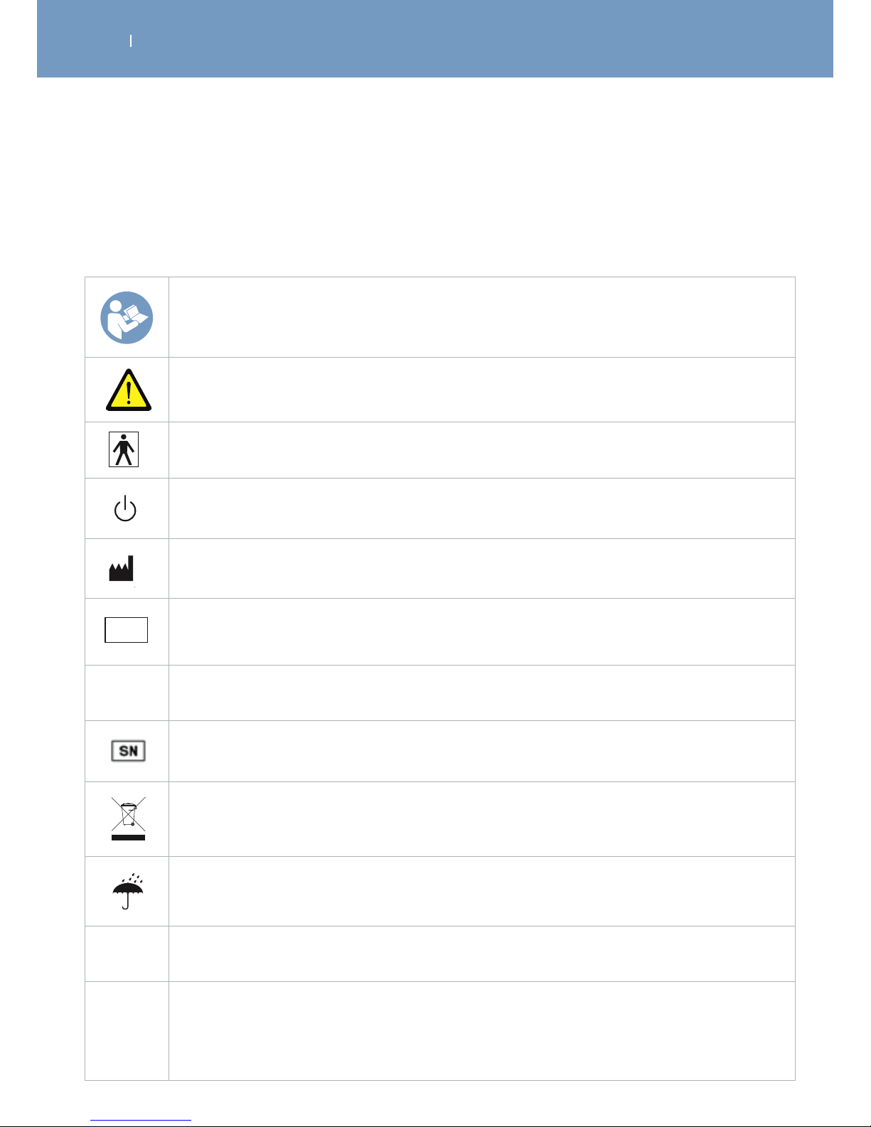
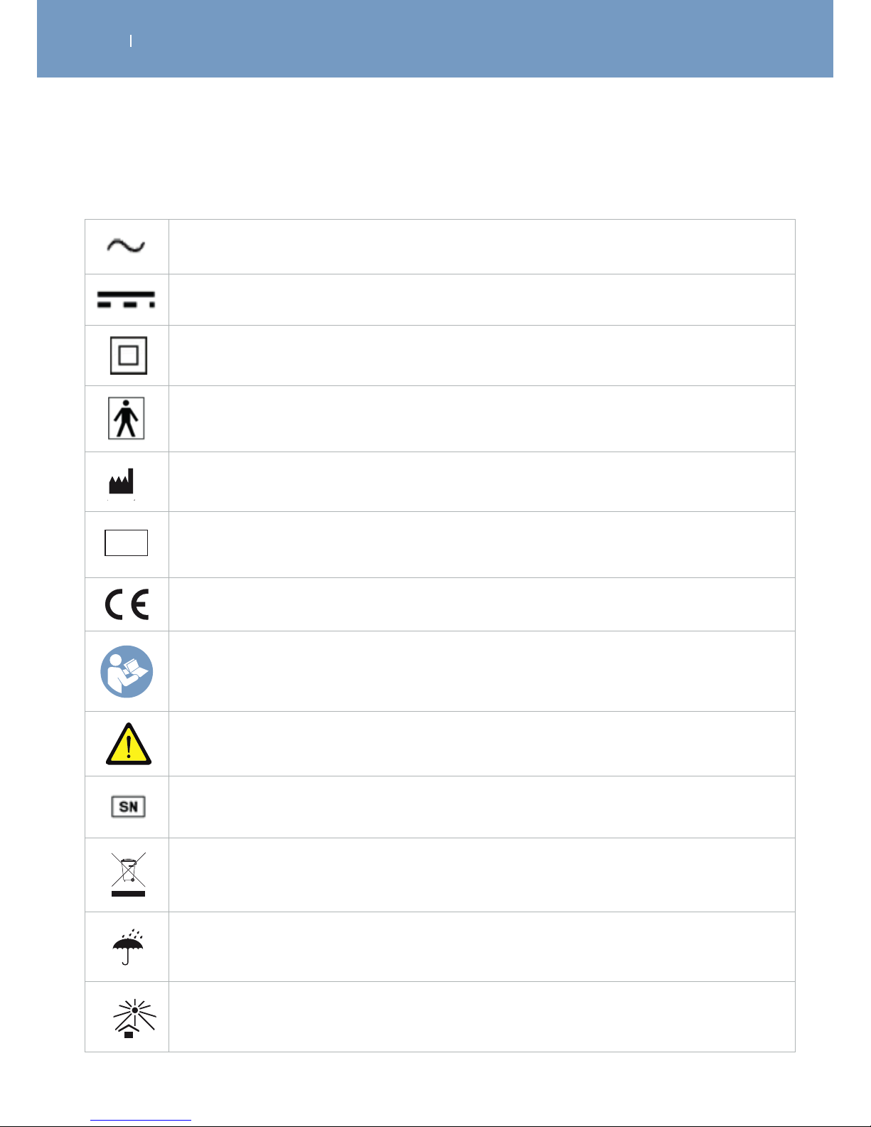
3.2 Explanation of symbols (connections and nameplates)
3.2.1 Symbols on device and AC Power Supply
Read the user manual or operating instructions
Caution! Observe warnings set forth in operation manual!
The Wireless Professional is a class II device with internal electric power and type BF
applied parts.
20xx
The power switch On/OFF button is a multi-function button.
20xx
The name and address next to this factory symbol is the manufacturer. The date is the
manufacturing date.
20xx
LATEX
FREE
REF
The number next to this symbol is the article reference number
CE
Device complies with Council Directive 93/42/EEC as amended, concerning medical devices.
The number next to this symbol is the serial number
20xx
WEEE Mark (European Directive 2002/96/EC). Indicates separate treatment from general
waste at end of life.
20xx
Keep dry
IP
IP
IP classification indicates the degree of protection and thus defines its suitability for use
under various ambient conditions.
IP 20 on the unit means the protection is eective against ingress of foreign solid objects
(diameter greater than 12.5 mm)
IP02 on the carrying case means the device is protected against ingress of water (when
tilted up tp 15°)
Page 22
. DESCRIPTION OF THE WIRELESS PROFESSIONAL
EN
WIRELESS PROFESSIONAL
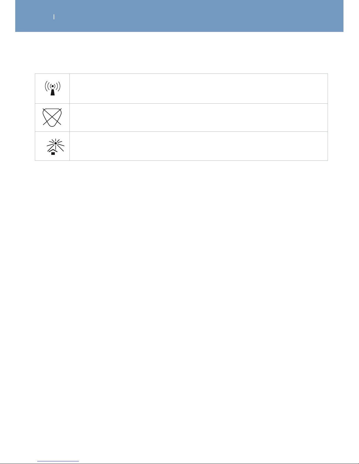
20xx
Non-ionising radiation
LATEX
Not made with natural latex rubber
20xx
Keep away from direct sunlight
Page 23
. DESCRIPTION OF THE WIRELESS PROFESSIONAL
EN
WIRELESS PROFESSIONAL
Alternating current input on AC power supply
Direct current output from power supply
Protection class II equipment. The AC Power Supply device has double insulation.
The Wireless Professional is a class II device with internal electric power and type BF
applied parts.
20xx
The name and address next to this factory symbol is the manufacturer. The date is the
manufacturing date.
20xx
LATEX
FREE
REF
The number next to this symbol is the article reference number
Device complies with Council Directive 93/42/EEC as amended, concerning medical devices.
Read the user manual or operating instructions
Caution! Observe warnings set forth in operation manual!
The number next to this symbol is the serial number
20xx
WEEE Mark (European Directive 2002/96/EC). Indicates separate treatment from general
waste at end of life.
20xx
Keep dry
20xx
Keep away from direct sunlight
3.2.2 Symbols on Charging Tablet/Docking Station and AC Power Supply
Page 24
. DESCRIPTION OF THE WIRELESS PROFESSIONAL
EN
WIRELESS PROFESSIONAL
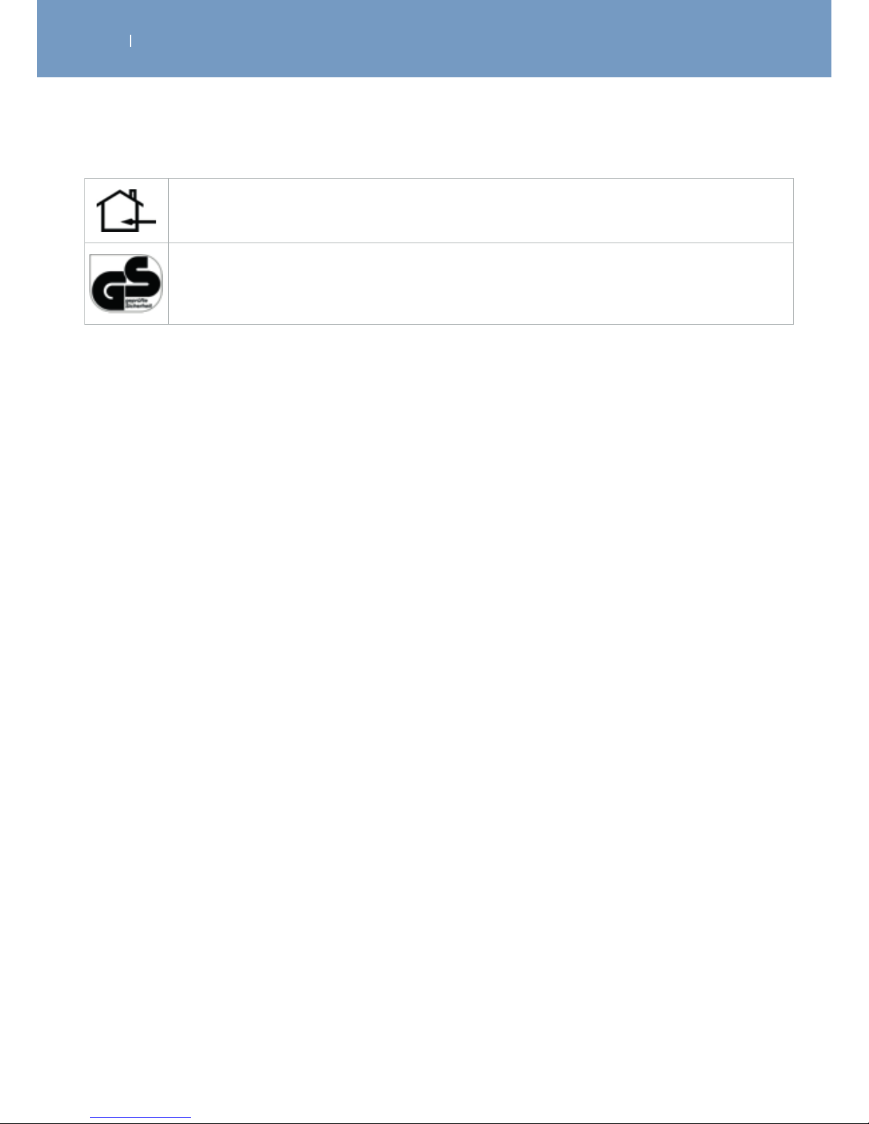
Indoor use only
The Geprüfte Sicherheit (“Tested Safety”) or GS mark indicates that the equipment meets
German and, if available, European safety requirement for electrical devices. Here, approved
by TÜV.
Page 25
. DESCRIPTION OF THE WIRELESS PROFESSIONAL
EN
WIRELESS PROFESSIONAL
3.3 Description of the device components
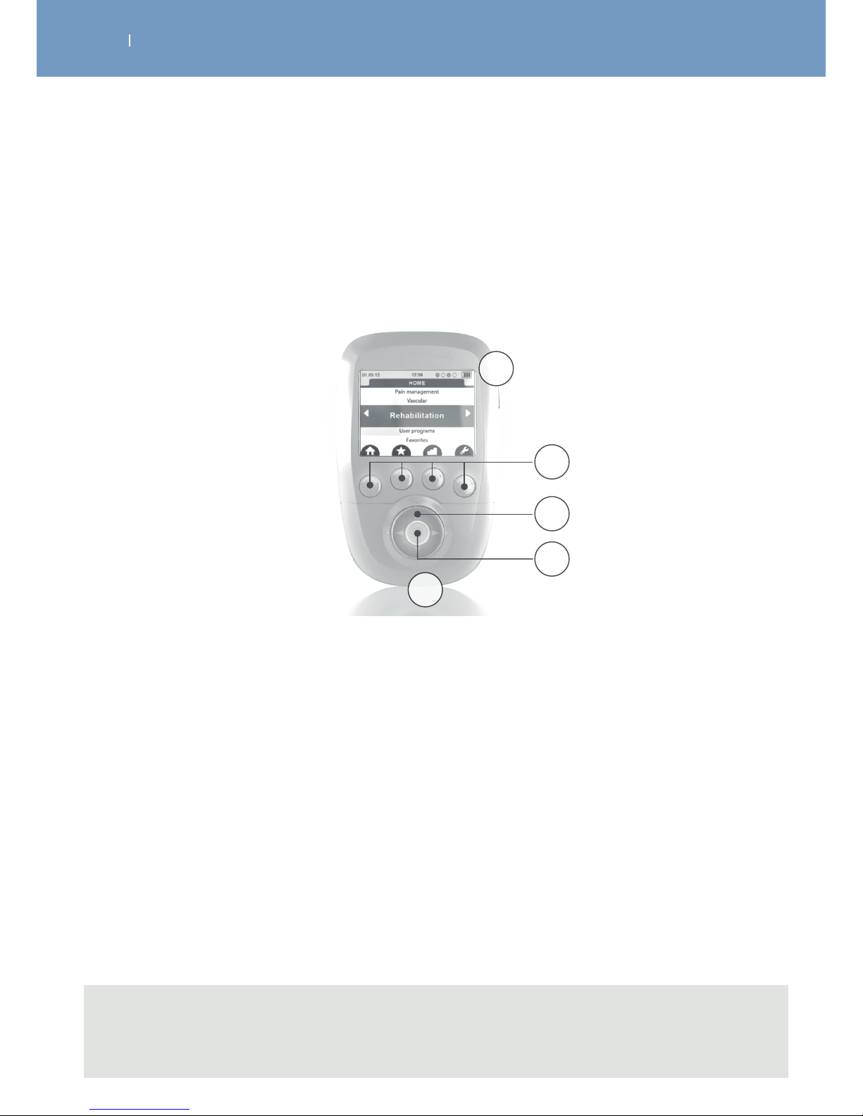
3.3.1 Remote Control
Note
Emergency stop function: By pressing the central button or the On/O button on one of the
modules during stimulation, the device pauses.
A On/O button (press briefly to switch on, press and hold for more than 2 seconds to switch o, while
browsing the lists press briefly to return to the main menu)
B 4 multifunction buttons:
• Functions related to icons are located on the screen (e.g.: info, main menu, placement of
electrodes, etc.)
• Selection of stimulation channel to increase or decrease the energy level of stimulation
C Navigation pad
D Validation or pause button during stimulation
E Port for the USB cable or the docking station connector
A
D
E
C
B
Page 26
. DESCRIPTION OF THE WIRELESS PROFESSIONAL
EN
WIRELESS PROFESSIONAL
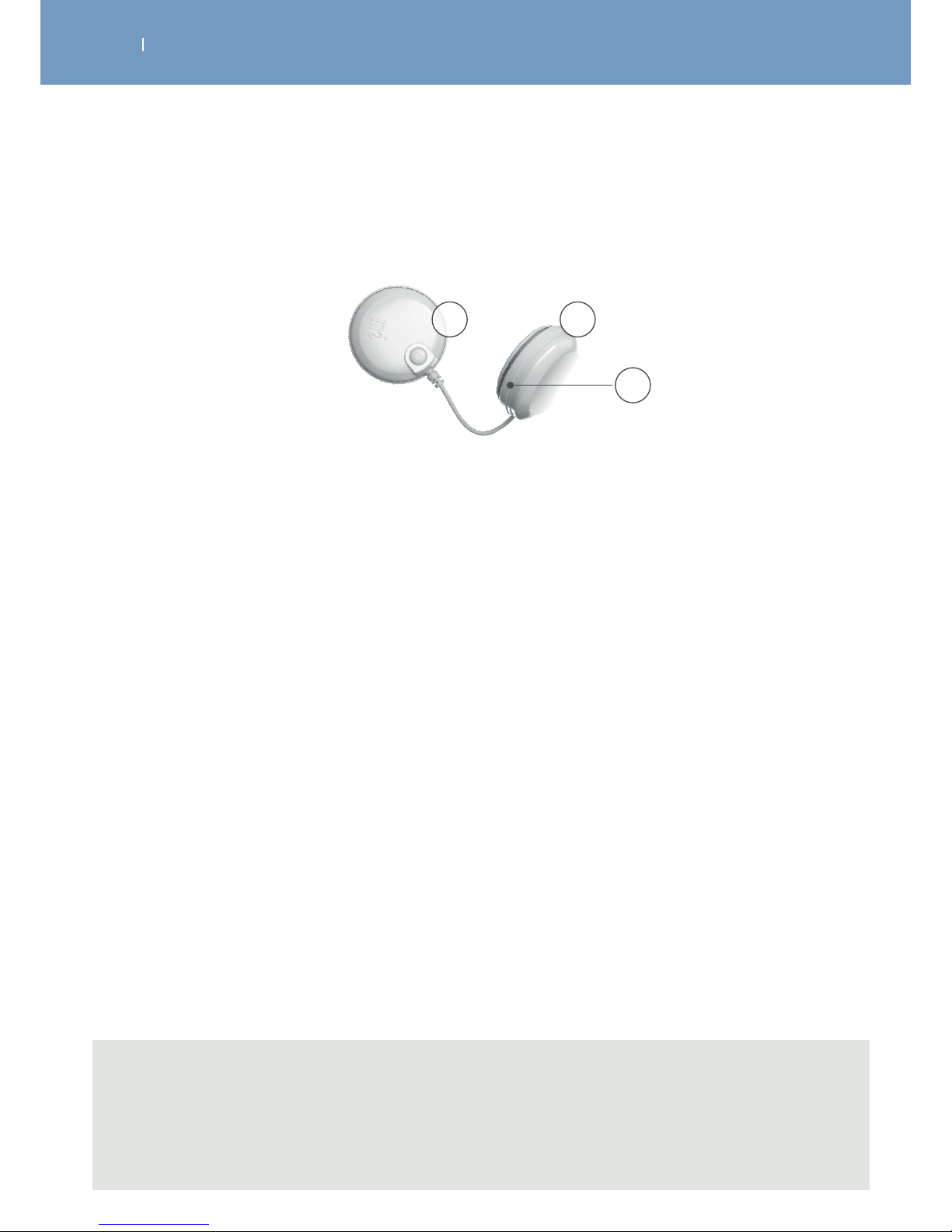
3.3.2 Modules
A module is composed of two pods.
A On/O button (press briefly to switch on, press for 1 second to switch o, during stimulation
press to pause)
• Flashing green LED: ready
• Flashing yellow LED: stimulation on
B Groove to wind up the cable
C Pod containing battery
A
B
C
Note
- When the distance among the remote control and the modules is too big, they will loose the
connection, stop with the stimulation immediately and the LEDs will flash red and green.
- Emergency stop function: By pressing the central button or the On/O button on one of the
modules during stimulation, the device pauses.
Page 27
. DESCRIPTION OF THE WIRELESS PROFESSIONAL
EN
WIRELESS PROFESSIONAL
3.4 Description of key accessories
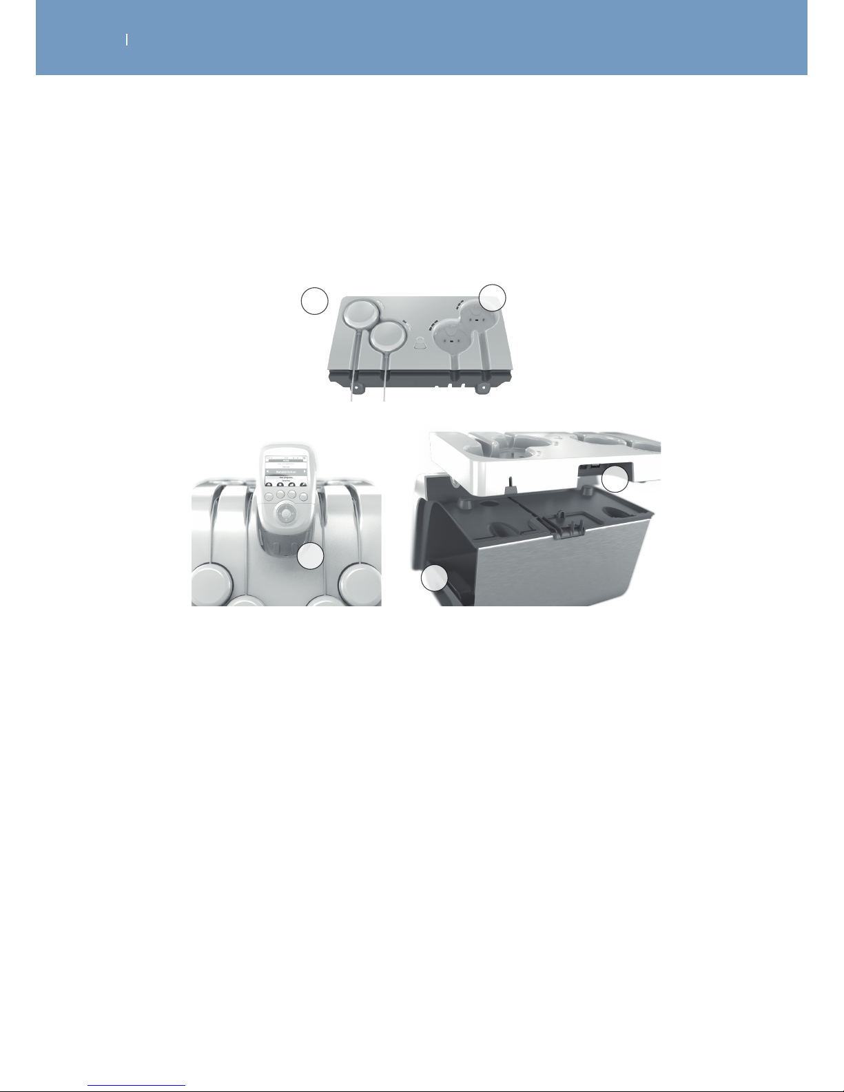
3.4.1 Smart 4CH docking station and Removeable tablet
A Removable tablet
B Connector to charge the remote control
C Docking bay to position the modules to be recharged
D Port for the AC adapter and for the USB cable connected to the front of the docking station
E Storage bin
D
C
A
E
B
Page 28
. DESCRIPTION OF THE WIRELESS PROFESSIONAL
EN
WIRELESS PROFESSIONAL
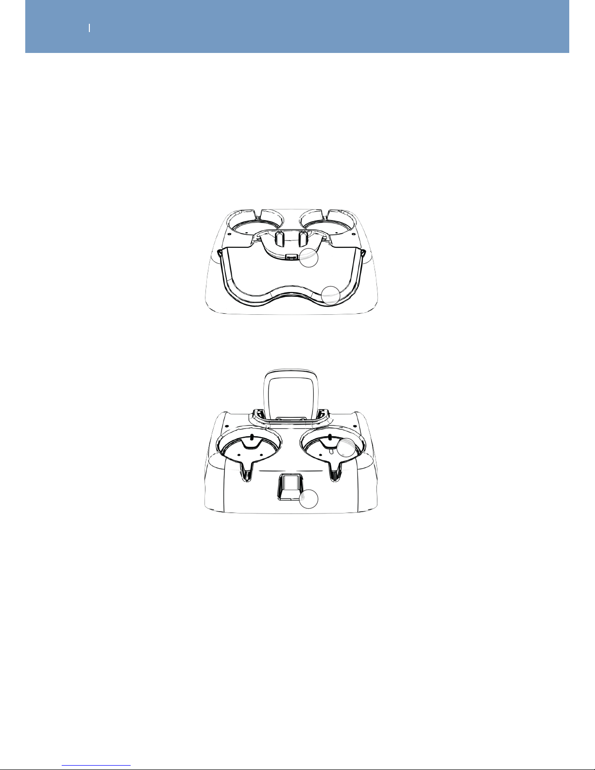
3.4.2 Basic 2 CH docking station
A Remote control charging connector
B Location for positioning the modules
C Location for positioning the modules to be recharged
D Charger plug
A
B
C
D
Page 29
. DESCRIPTION OF THE WIRELESS PROFESSIONAL
EN
WIRELESS PROFESSIONAL
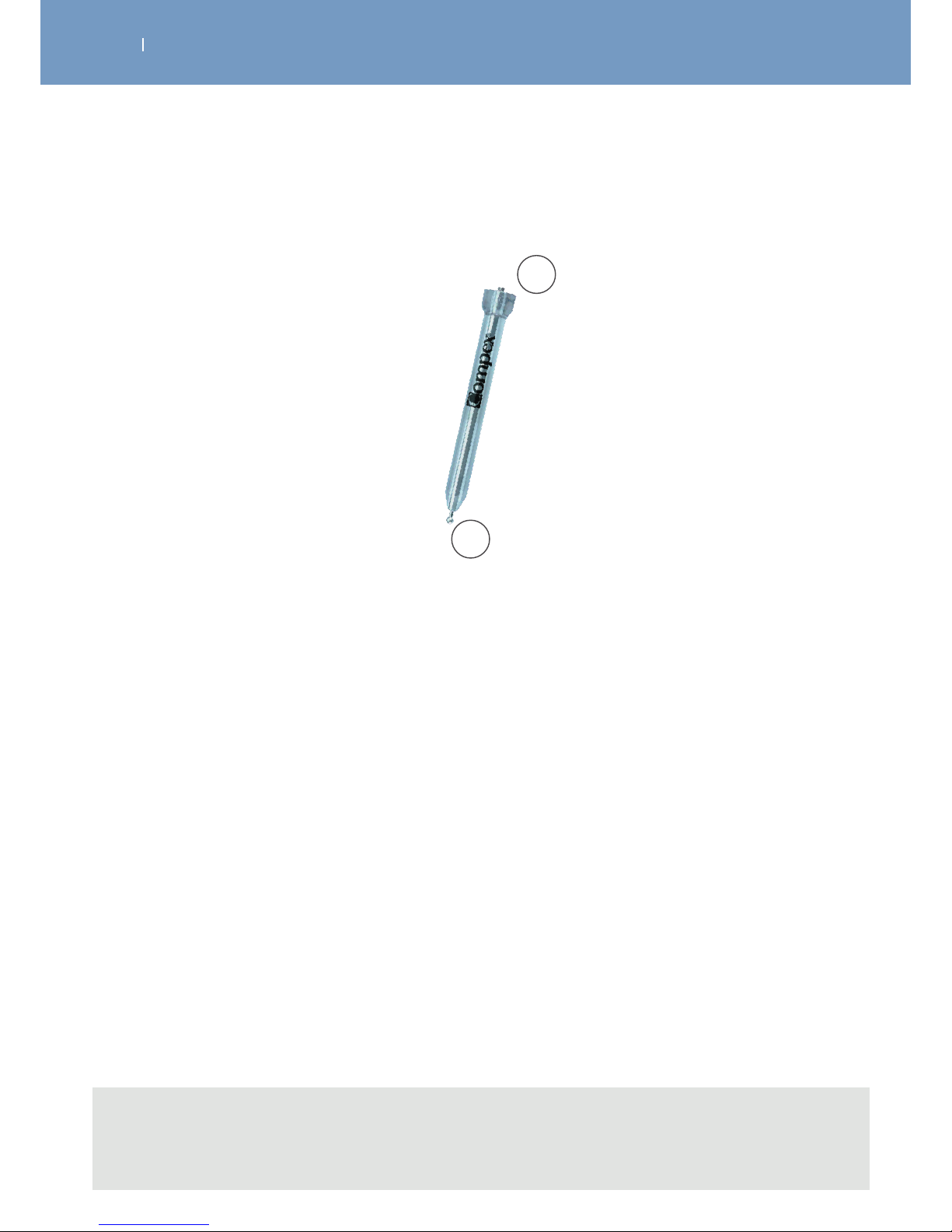
3.4.3 The Motor Point Pen
Note
- For detailed information on the usage of the motor point pen please see Rev. 6.1
- Always use the conductive gel that comes with the product with the motor point pen.
A Tip of the motor point pen, to locate the motor point
B Snap connection for the positive pod of the module (pod with illuminated button)
A
B
Page 30
. DESCRIPTION OF THE WIRELESS PROFESSIONAL
EN
WIRELESS PROFESSIONAL
3.5 Description of key Displays shown
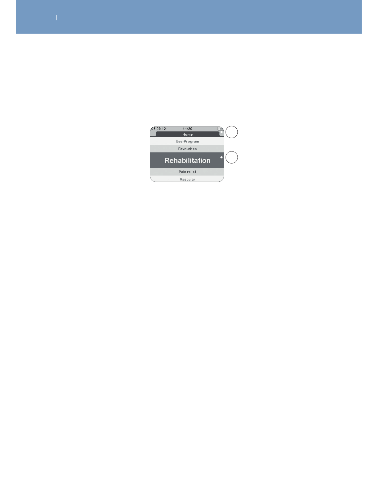
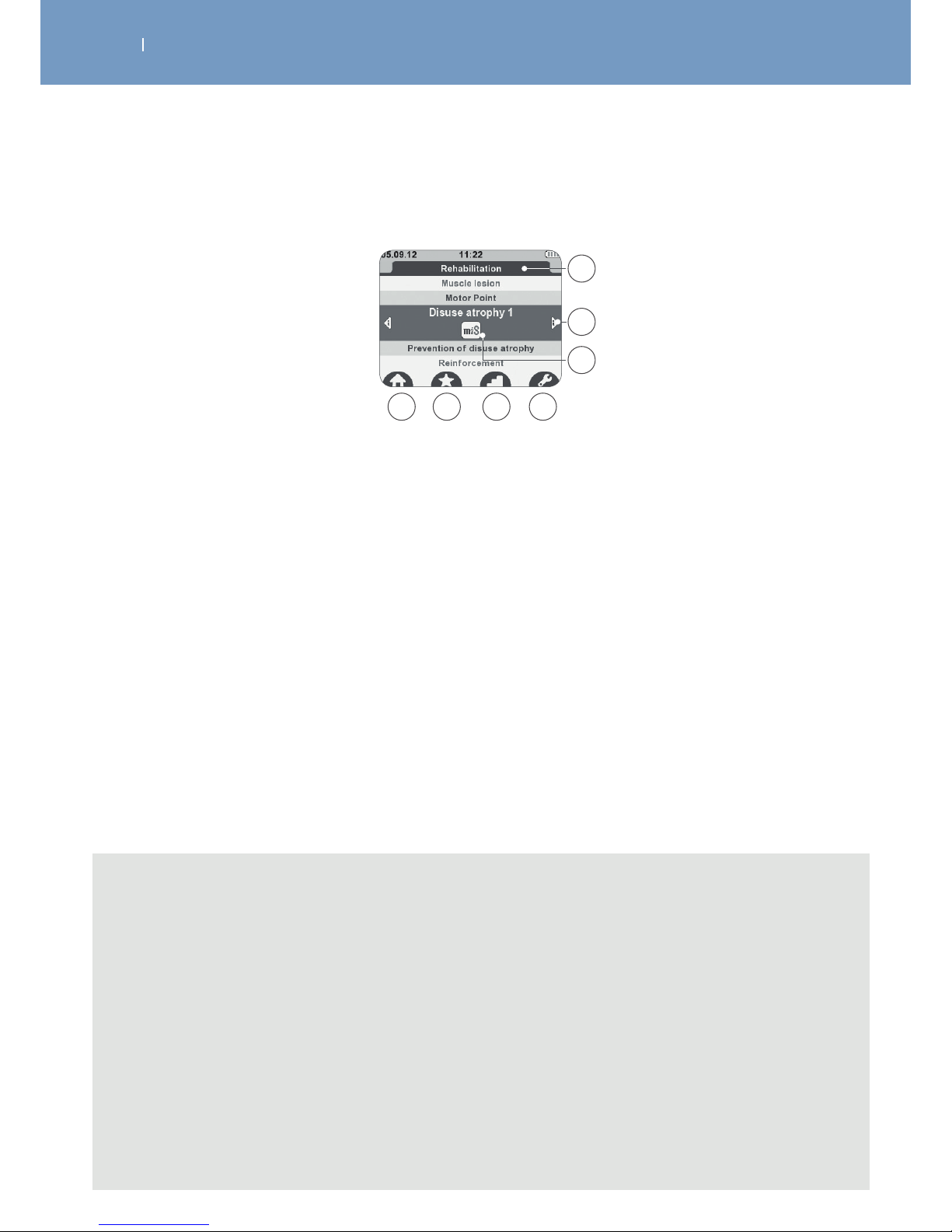
3.5.1 Display in Programme Category selection mode (Home Screen)
A
B
A Header showing date, time and battery status
B Current chosen program category (marked with a blue focus, displayed bigger)
Page 31
. DESCRIPTION OF THE WIRELESS PROFESSIONAL
EN
WIRELESS PROFESSIONAL
3.5.2 Display in Programme selection mode
A Name of the programme category
B Additional programme information
C Visualisation of programme options
D Back to main menu
E Adding programme to Favourites list
F Selection of programme level
G Configuration of programme options
A
C
D E F G
B
Note
- For the visualisation of the program information (B), please use the left/right direction of the
navigation pad, and scroll within the information by using the up/down direction of the navigation
pad.
- To add a program to the Favourite list (E), please press the multifunction button below the icon
while program is marked. Press the button again to remove the program from the Favourite list.
- If dierent program levels are available, icon “F” will be displayed. To change the program levels,
please press the button below the icon. Up to 3 dierent levels might be available. From level to
level dierent parameters (e.g. frequency, pause duration etc.) are changing to make the
treatment more challenging according to the process in rehabilitation (level 1 for beginners, level 3
for trained persons).
- If programme options are available icon “G” will be displayed. Please press the button below the
icon to enter the program option setting screen
Page 32
. DESCRIPTION OF THE WIRELESS PROFESSIONAL
EN
WIRELESS PROFESSIONAL
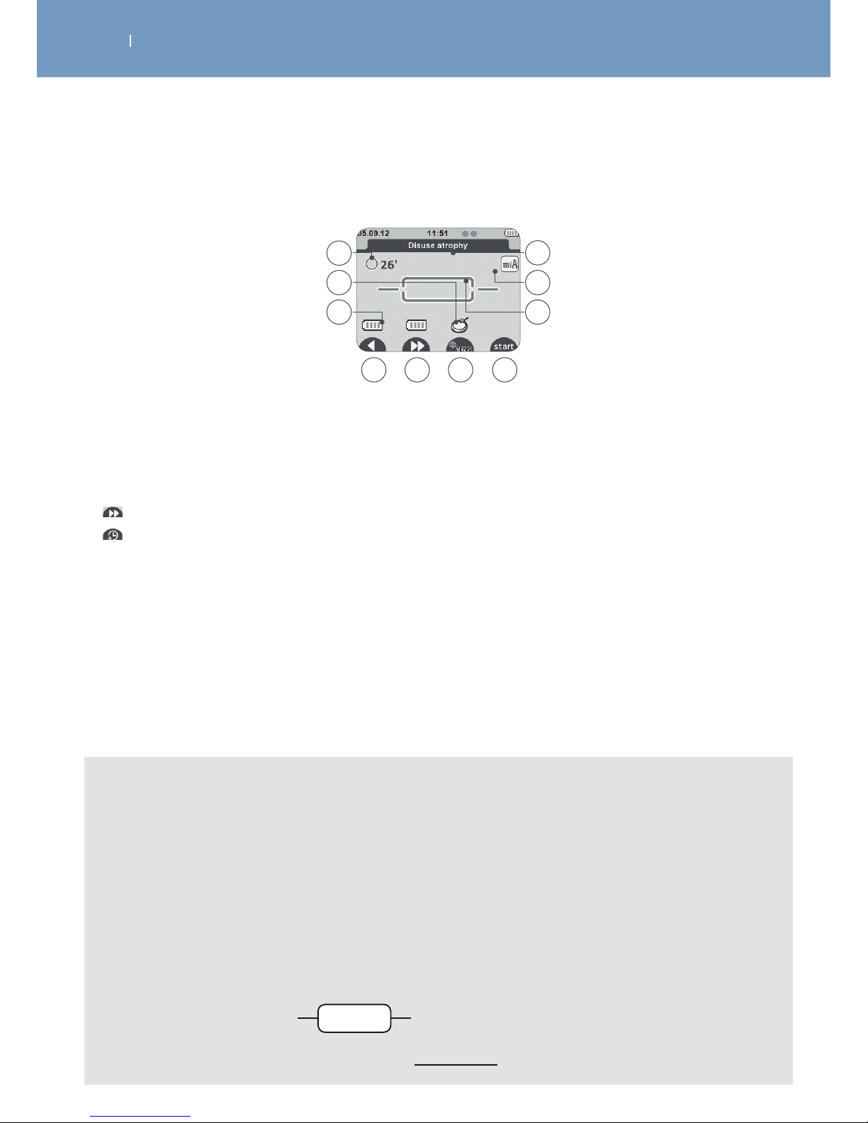
3.5.3 Diplay when programm is selected, Modules need to be turned on, mode
A Total programme time (minutes)
B Module activation indication
C Module battery level
D Back to previous menu
E Skip function allows you to jump programme sequences (if available) or
Programme time increase function (if available)
F +TENS function (if available)
G Start Session
H Programme architecture
• 3-sequence programme: Warm-up, Work, Relaxation
• Programme with 1 continuous sequence
I Active option in the programme
J Programme name
C
D F G
A
B
E
H
I
J
Note
- “B” the device asks you to activate the next module. 1 module needs to be activated at least
(1-channel treatment). After activating the number of channels required for the treatment
(1 up to 4) press start to start the treatment.
- “E” functions are not available within all programs, symbols will only be displayed in programs
available
- “F” the “+TENS” function allows you to combine a TENS programme with a selected basic
programme. The function will be displayed for the channels if available. (see as well …)
- “H” the dierent program architectures are:
• 3-sequences program:
a) Warm-up
b) Work
c) Relaxation
• 1-sequence program, a) continuous work
ba c
a
Page 33
. DESCRIPTION OF THE WIRELESS PROFESSIONAL
EN
WIRELESS PROFESSIONAL
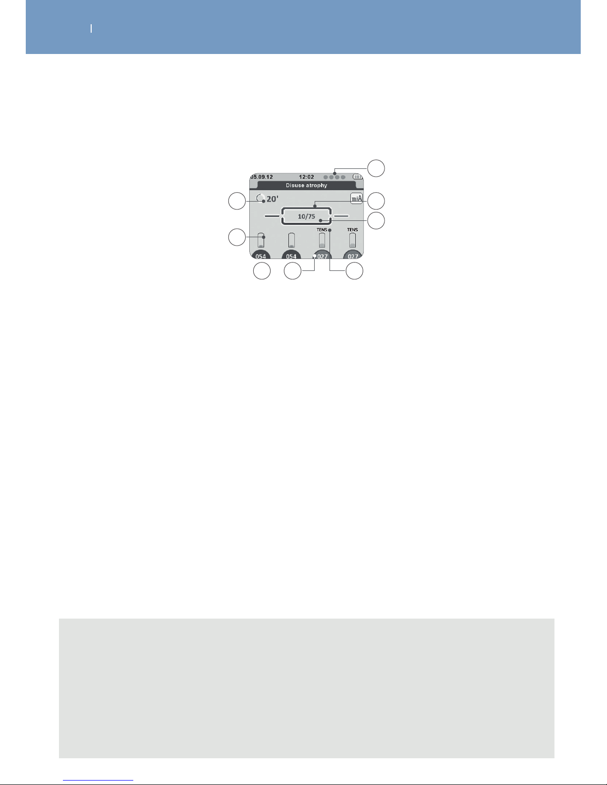
3.5.4 Display during treatment
A Total remaining programme time (min)
B Energy level bar graph for each channel
C Energy level for each channel
D Intensity background is:
Dark background = active channel
Bright background = inactive channel
E Indication relating to the channel:
• TENS: channel providing a TENS current
• I-II: channel group
F Number of contractions remaining / total number of contractions
G Indicator of programme execution
H Number and order of attached channels. Circle = channel recognised but module turned o.
C D E
A
B
G
H
F
Note
“D” intensity control
- Channels can be selected/de-selected by pressing the corresponding button below.
- To change intensity during treatment, channel needs to be selected (dark blue background).
- While channel is not selected (light blue background) stimulation will be performed with the set
intensity.
- This function allows you to change the intensity for each channel itself or more than 1 at the same
time (by marking the designated channels).
Page 34
. DESCRIPTION OF THE WIRELESS PROFESSIONAL
EN
WIRELESS PROFESSIONAL
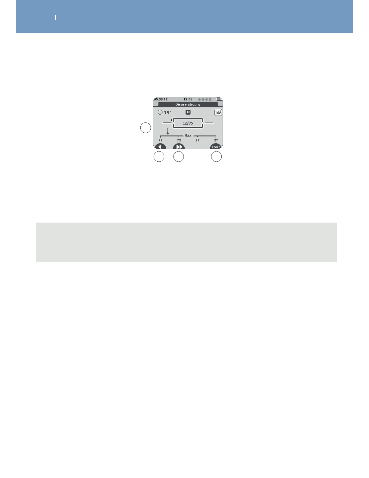
3.5.5 Display during pause in treatment
A Maximum energy level achieved by the channel during contraction phases
B Back to previous menu
C Skip function allows you to skip programme sequences (not available for all programmes)
D Resumes the stimulation session
A
B C D
Note
Emergency stop function: By pressing the central button or the On/O button on one of the
modules during stimulation, the device pauses.
Page 35
. DESCRIPTION OF THE WIRELESS PROFESSIONAL
EN
WIRELESS PROFESSIONAL
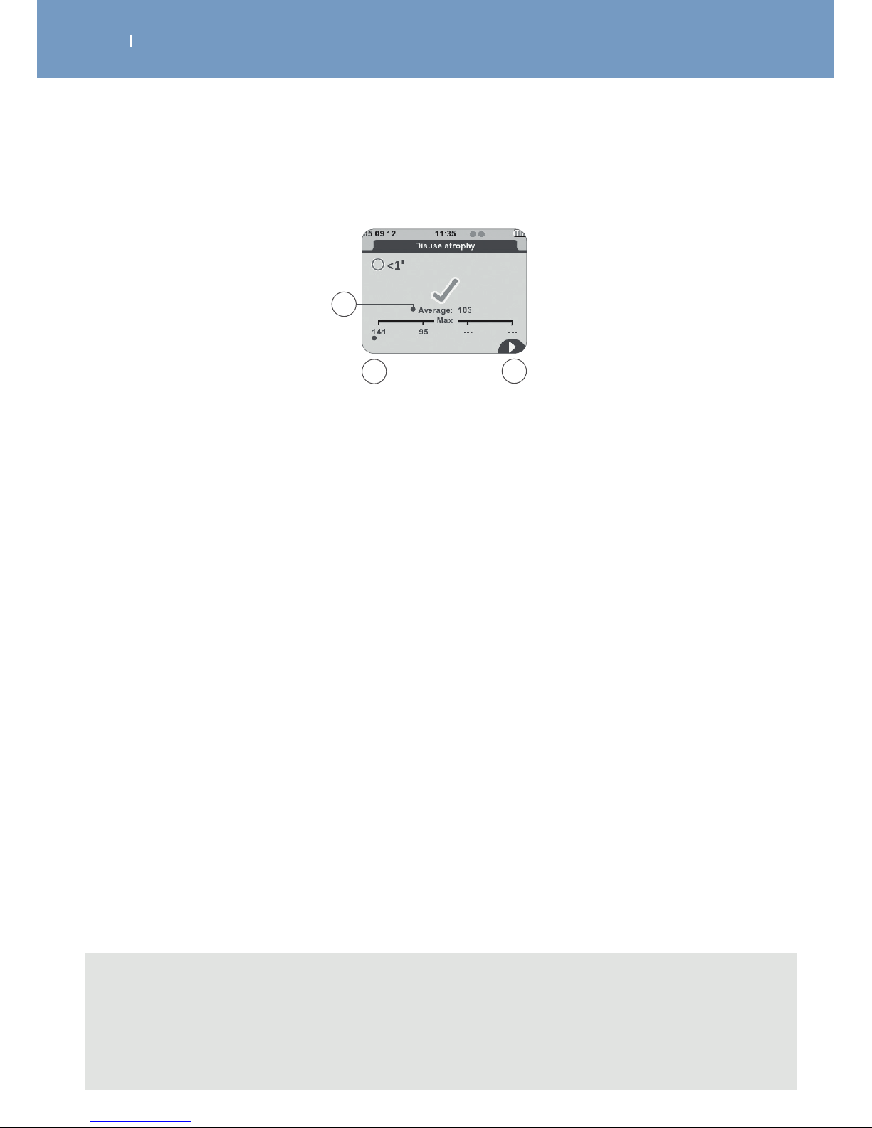
3.5.6 Display at the end of a treatment
Note
- For programs using the mi-range feature the percentage of time spent above the minimum
threshold will be displayed as well.
- To turn the unit o, press the On/O button on the remote control for more than 2 seconds. This
will switch o as well all modules.
A Average energy level of all the channels used during the contraction phase
B Maximum energy level achieved by the channel during contraction phases
C Back to main menu (HOME). For programs using the mi-range feature the percentage of time spent
above the minimum threshold is displayed.
A
B
C
Page 36
. DEVICE SETUP
EN
WIRELESS PROFESSIONAL
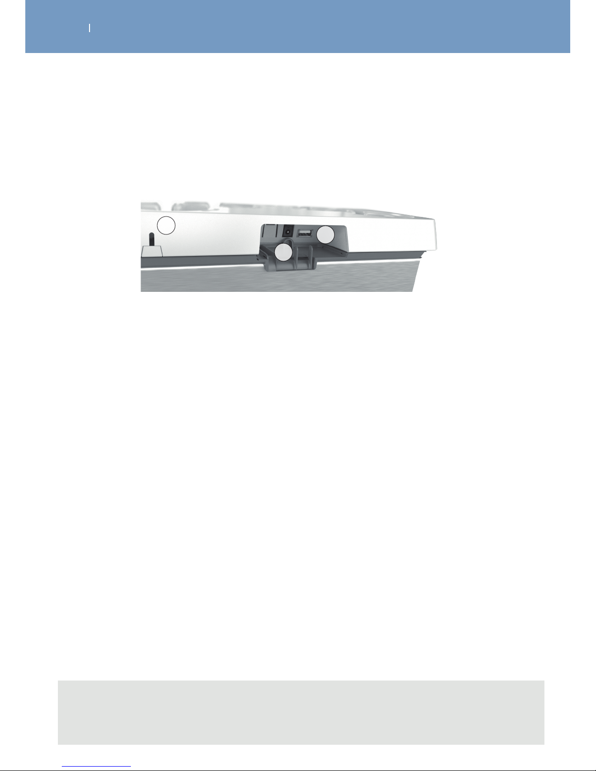
4.1 Smart 4CH Docking station - Connecting the unit, performance check
Connect the AC adapter supplied with your device to the removable tablet of the docking station (B) and
plug it into a power socket. Also connect the docking station’s USB cable to the removable tablet (C).
A Rear view of the docking station
B Connector for the AC adapter
C Connector for the USB cable
A
B
C
Note
- It is highly recommended to fully charge the batteries of the remote control and modules before
first use to improve their performance and life span.
Page 37
. DEVICE SETUP
EN
WIRELESS PROFESSIONAL
4.2 Charging the Remote Control and the Modules
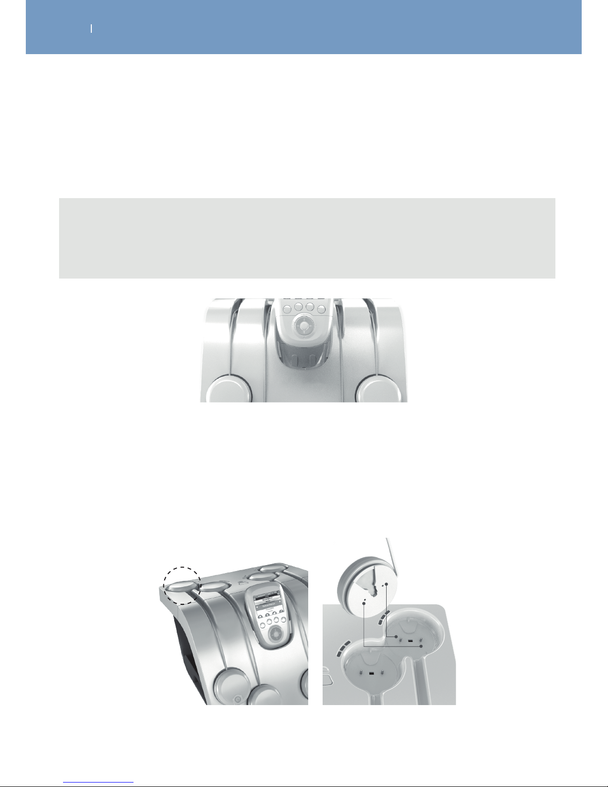
Charge the Remote Control by plugging it into the Docking Station.
Take care that the USB connector is pluged into the Remote Control.
Note
- The Remote Control can be charged by using the USB connector connected with the tablet
allowing it to charge modules and remote at same time. Remote control can also be directly
connected to a computer by using USB connector.
Charge the Modules:
Place the modules into the slots provided for this purpose.
To do this place the pod without the On / O button in the location indicated with the dotted line.
Do the same for the other modules.
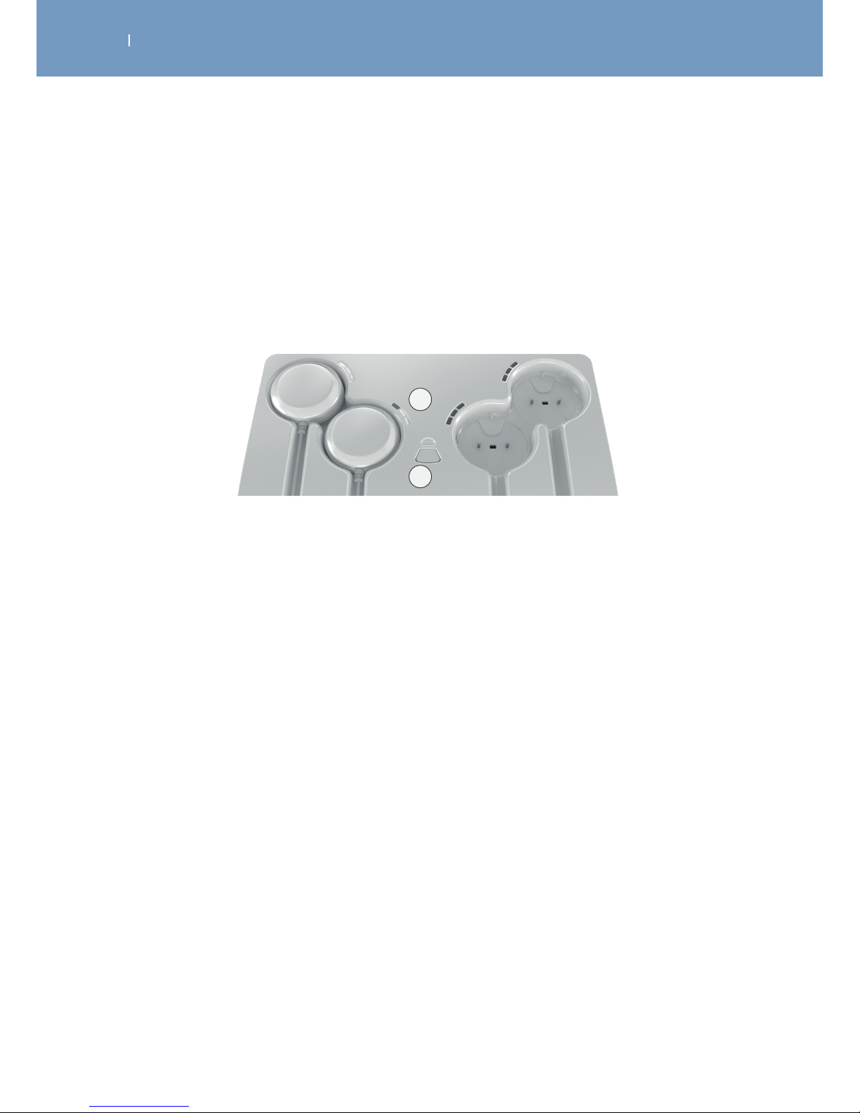
Once the modules are placed for charging, their battery level is shown by the blue LEDs of the docking
station.
Page 38
. DEVICE SETUP
EN
WIRELESS PROFESSIONAL
A
B
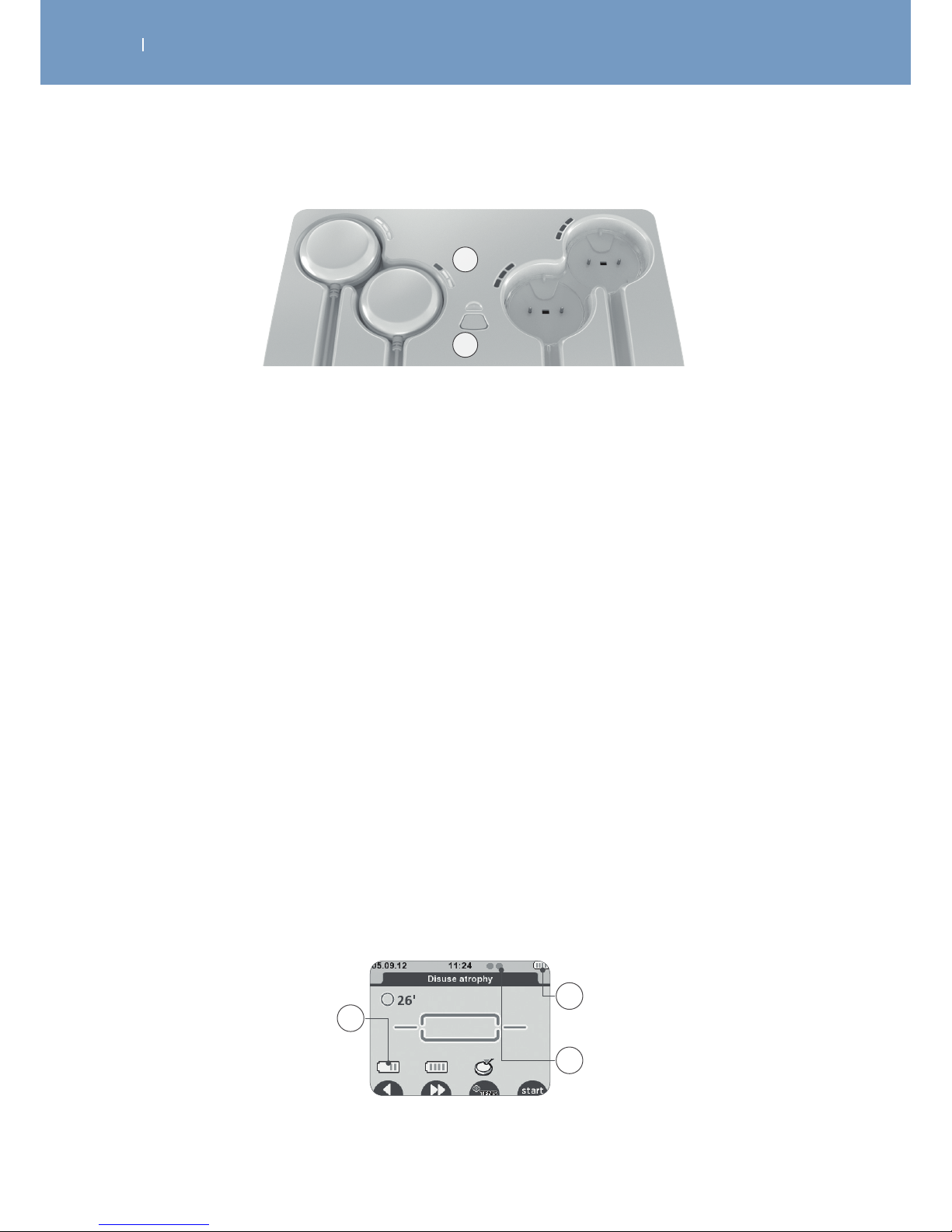
A First LED blinking = low battery
Second LED blinking = battery level average, a session can be performed
Third LED blinking = good battery level
All LEDs are lit and not blinking any more = battery completely full
B The LED above the button indicates that the tablet is connected to the power supply. It lights:
Blue = modules can be charged
Red = right after connecting to the power supply during self test
The button allows synchronizing modules and remote control, which is usually done automatically by the
unit.
Battery level
In the screen “Modules need to be turned on”, the module battery level is displayed on the corresponding
channel at the remote control, when you turn the module on, just before starting the stimulation session.
The battery level of the remote control is always visible in the upper right corner.
Small green indicators show how many modules are turned on and recognised by the remote control.
The batteries of the remote control and the modules are designed to stand at least 3 days with 5
treatments per day.
A Module battery level
B Remote control battery level
C Number of modules switched on and recognised by the remote control
A
C
B
Page 39
. DEVICE SETUP
EN
WIRELESS PROFESSIONAL
4.3 Multi-Sessions mode – Synchronisation with few remotes and Smart 4CH
Docking station
Smart 4CH Docking station is able to synchronise any Wireless Professional module(s) and remote(s)
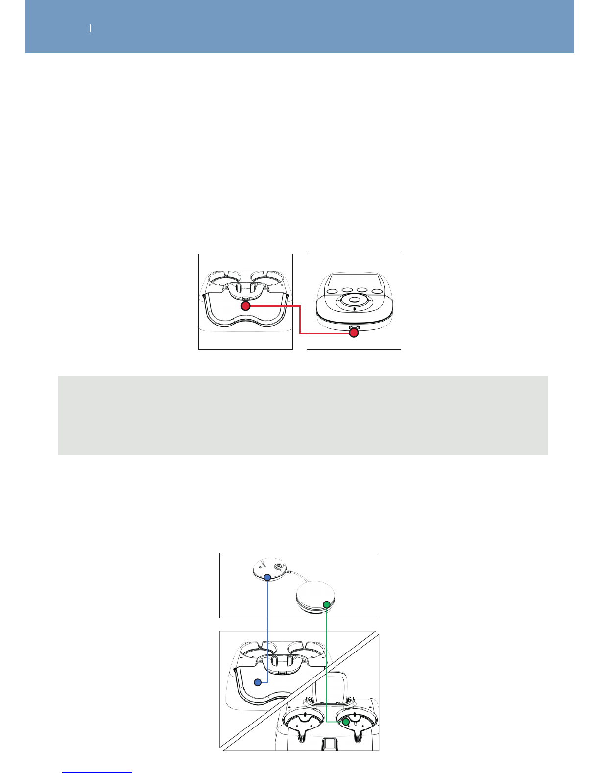
plugged on it. Modules plugged on the station will be automatically synchronized and recognized by
the remote plugged as well on the station. The B button described in 4.2 Chapter allows synchronizing
Modules and Remote control which is usually done automatically by the unit.
A
B
If you are using 2 or more remotes with the same docking station, you will be able to manage separately
2 or more sessions at the same time. Remotes and respective synchronized modules are under separate
control until the next synchronization. Sessions can be started independently.
First, plug the number of module(s) necessary for Session 1 (1, 2 or 3 modules) plus the first remote to be
synchronized.
After plugging o modules and remote in use for session 1, plug the remaining modules and the second
remote to be synchronized for Session 2.
Same process is applicable for several remotes.
Note: 2 kinds of sleeve protection (white and blue) are delivered with the 4CH devices to allow recognition
between remotes.
Page 40
. DEVICE SETUP
EN
WIRELESS PROFESSIONAL
4.4 Basic 2CH Docking station - Connecting the unit, performance check
Connect the AC adapter supplied with your device to the docking station and then plug it into a power
outlet. It is strongly recommended that you fully charge the remote control batteries and modules before
first use in order to improve its performance and life expectancy.
Charge the Remote Control by plugging it into the Docking Station.
Take care that the USB connector is pluged into the Remote Control.
Note
The Remote Control can be charged as well by using the USB connector, which comes with your kit
and connect it with the tablet and remote control to charge modules and remote at same time or by
connecting the remote control to a computer.
Charge the Modules:
Place the modules into the slots provided for this purpose.
To do this place the module without the On / O button in the location indicated with the dotted line. Do
the same for the other module.
Page 41
. HOW TO PERFORM A TREATMENT, PERFORMANCE CHECK
EN
WIRELESS PROFESSIONAL
See also Chapter “Description of the Wireless Professional”
1. Turn the Remote Control on, by pressing the On/O button.
2. Upon activation the screen displays a list that gives you access to the categories of programmes.
3. Select a program category by using the navigation pad (up/down)
4. Confirm your choice with the centre button.
Note
- When you turn on the remote control the first time, the language set up will be displayed first.
Chose your preferred language and press the center button to proceed.
- Once you have created your list of favourite programmes, it will be displayed first after switching
on the remote control.
Note
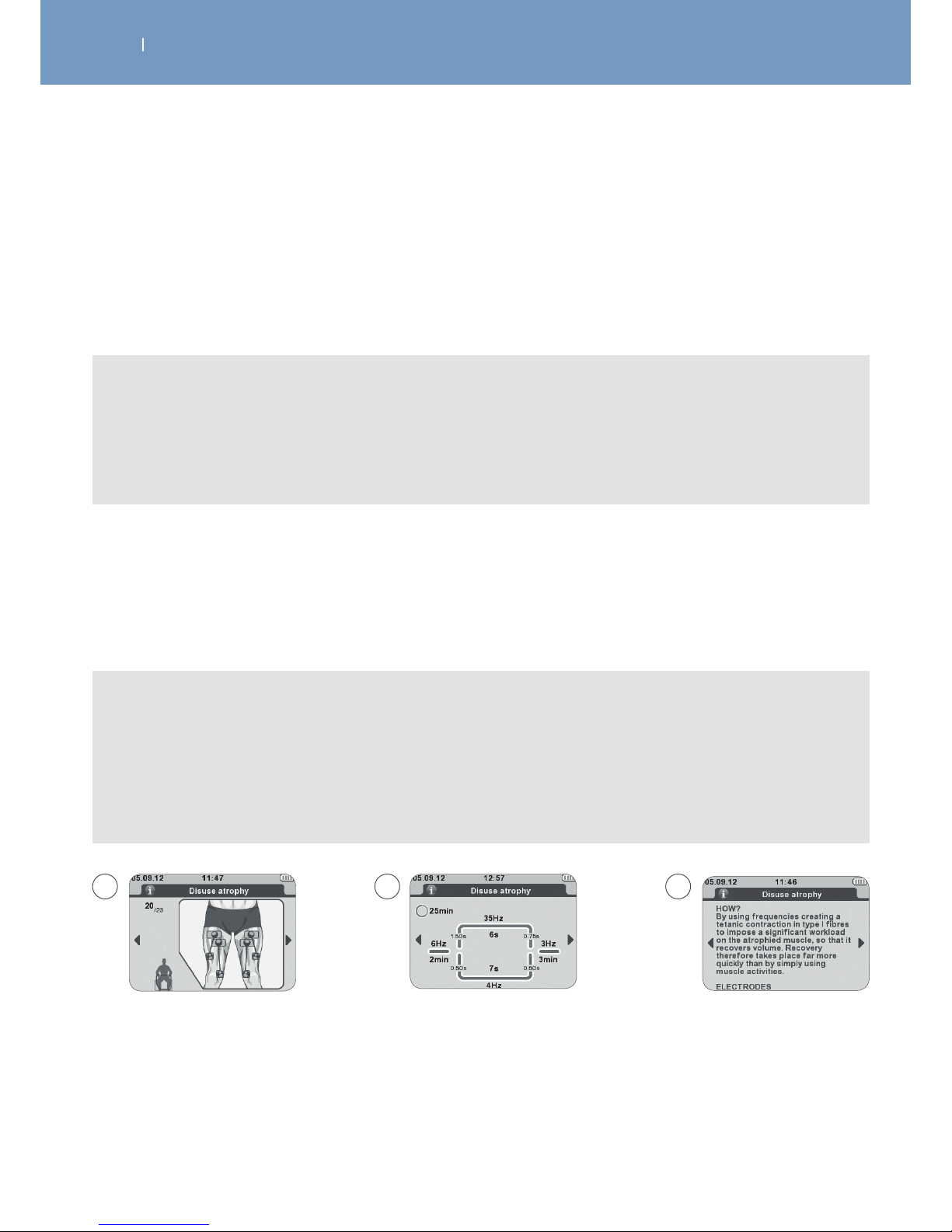
- Additional information about the programmes, such as electrode placement, program parameters
and program explanation, is available.
- Use the navigation pad (left/right) to display them and to scroll (up/down) within an explanation
for getting more information.
- You can find the program information as well within this manual.
5.1 Select a Program
After selecting a programme category the available programs within this category will be displayed.
To select a program, use the navigation pad (up/down) and confirm your choice with the centre button.
A Placement of electrodes applicable to the programme
B Programme parameters
C Programme explanation
A B C
Page 42
. HOW TO PERFORM A TREATMENT, PERFORMANCE CHECK
EN
WIRELESS PROFESSIONAL
5.2 Adjust treatment options
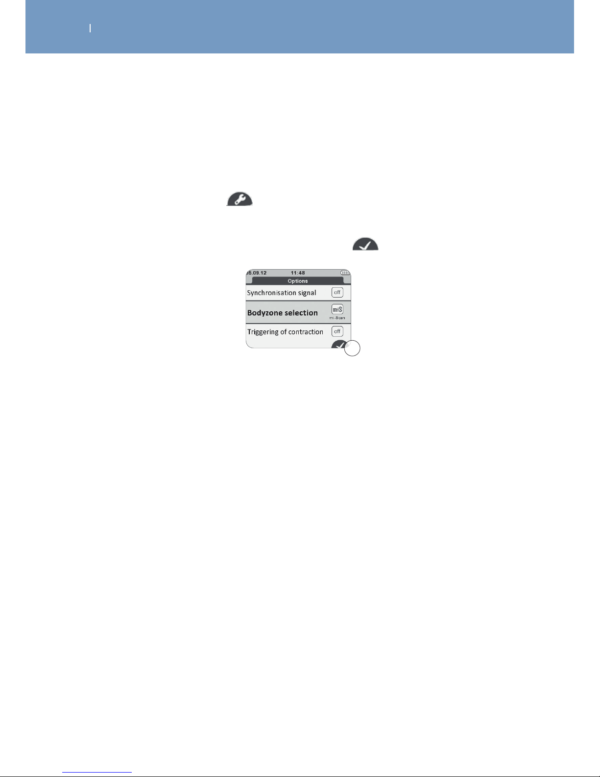
For most programmes, dierent options can be enabled or disabled.
For detailed descriptions of the options available see: Chapter “Treatment Options”
1. Press the program options button to enter the options menu.
2. To mark an item, use the navigation pad (up/down).
3. To change settings of the marked option, use the central button.
4. To store the changed settings press the confirmation button
5.3 Electrode placement
The placement of the electrodes belongs to the indication that is supposed to be treated.
Please find detailed recommendations regarding the electrode placement:
- within usage of the Motor Point Pen
- within specific indications
- within your Wireless Professional
Depending on the characteristics of the current used for each programme, the electrode connected to the
positive pole (pod with illuminated button) may benefit from a “prime” location that is likely to increase
the ecacy of the treatment.
This is the case particularly for muscular electrostimulation programmes requiring strong muscular
contractions, for which it is recommended that the electrode with positive polarity is placed on the motor
point of the muscle.
The choice of electrode size (large or small) and the correct positioning of the electrodes on the muscle
group that needs to be stimulated are determining factors and are essential for stimulation to be eective.
As a result, always use the size of the electrodes shown on the images. Unless advised otherwise by a
doctor, always follow the positions specified on the images.
A
A Confirm / store program option settings
Page 43
. HOW TO PERFORM A TREATMENT, PERFORMANCE CHECK
EN
WIRELESS PROFESSIONAL
5.4 Body positioning of the patient
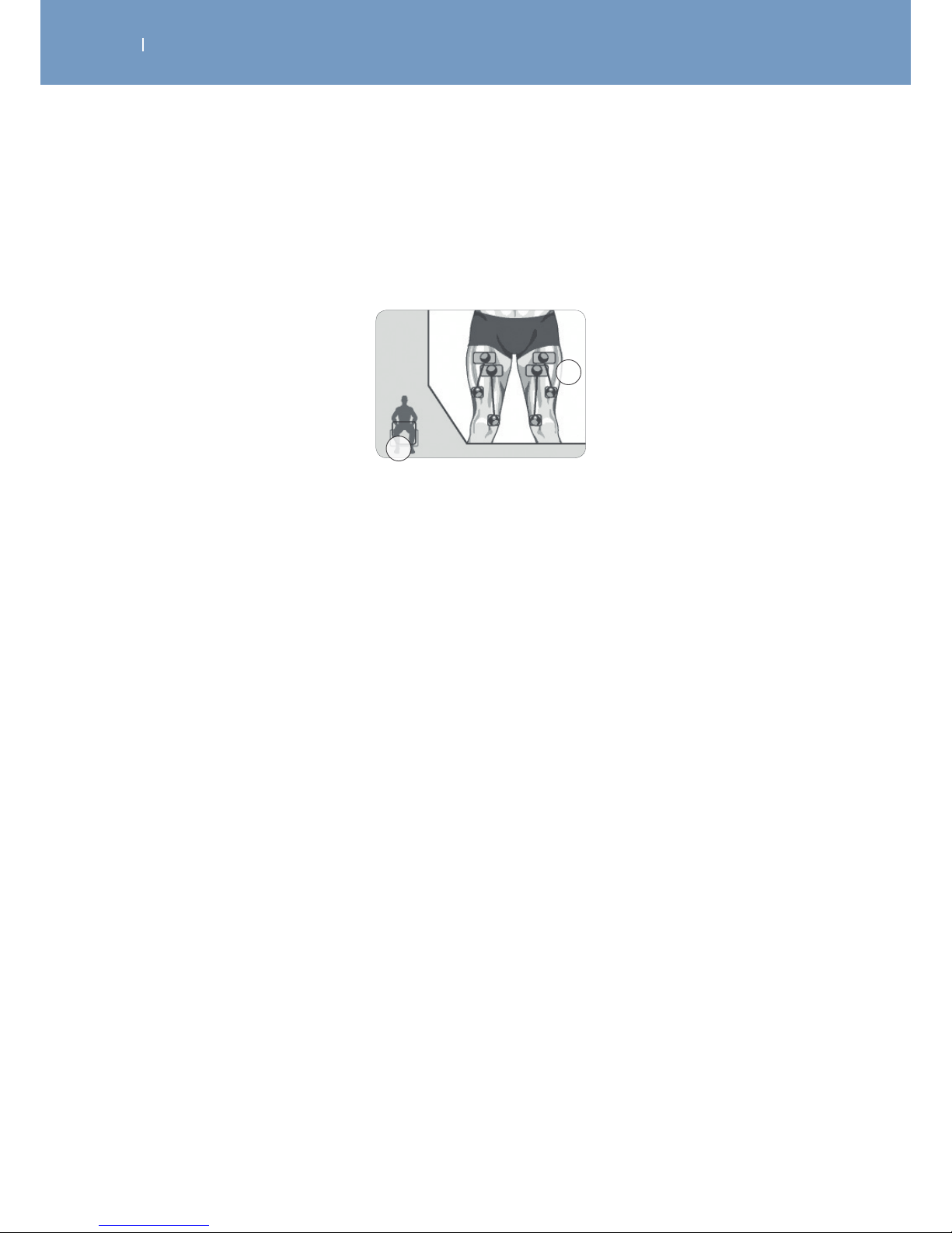
To determine the stimulation position to be used based on the position of the electrodes and the
programme chosen, please refer to the images of where the electrodes are positioned.
A Body position
B Positioning of the electrodes
A
B
The position of the person to be stimulated depends on the muscle group that requires stimulation and on
the programme chosen.
For programmes requiring muscle contractions (tetanic contractions), working the muscle isometrically is
always recommended to prevent cramps and muscle soreness after the session. For example, when the
quadriceps are stimulated, the patient will be placed in a seated position with the ankles fixed with straps
to prevent the knees extending. For other types of programmes (for example, analgesic programmes),
which do not cause muscle contractions, position the patient as comfortably as possible.
Page 44
. HOW TO PERFORM A TREATMENT, PERFORMANCE CHECK
EN
WIRELESS PROFESSIONAL
5.5 Connecting the modules to the electrodes
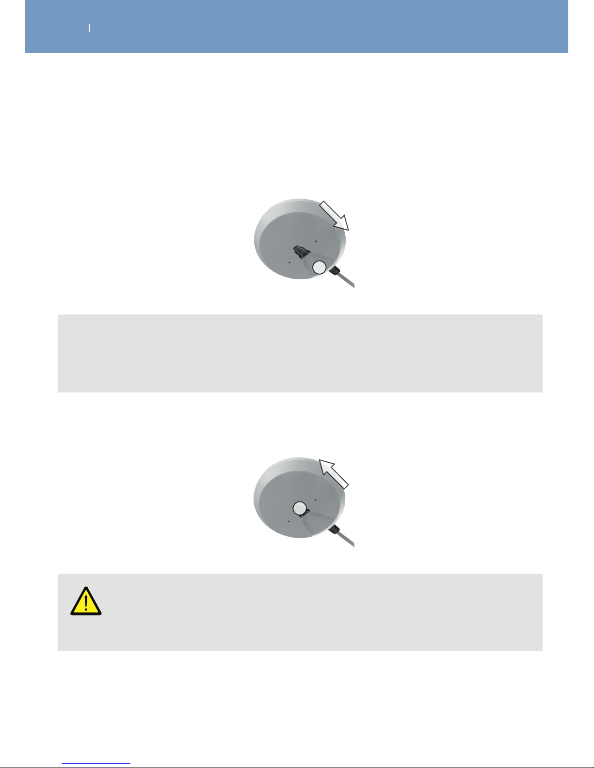
Once the electrodes are stuck to the skin of the patient, fix the pods by sliding them onto the electrode
snap until it clicks into place.
Note
The insertion direction marked by:
- the On/O button on the main pod
- a small vertical line on the housing of the other pod.
To remove the modules from the electrode simply make the opposite movement.
Caution!
Equipment damage Pulling the pods without respecting their pulling direction can damage the attachment
system.
A stimulation module consists of two poles:
• A positive pole (+) = the pod with an illuminated button
• A negative pole (-) = the other pod of the module
A separate electrode must be connected to each of the two pods.
Page 45

. HOW TO PERFORM A TREATMENT, PERFORMANCE CHECK
EN
WIRELESS PROFESSIONAL
5.6 Starting the treatment
Before starting the stimulation, the remote control asks you to turn on the modules, one after the other,
by pressing their button On/O.
For each module detected by the remote control, the device will prompt you to switch on another, up to a
maximum of 4 modules.
If you want to use a limited number of modules for your session, press the START button after the number
of modules you want has been detected.
After activating the modules, press START to start with the therapy:
• Stimulation always starts at intensity level 0.
• Select a channel to change the intensity by pressing the corresponding button.
• The channel will be marked dark blue.
• Use the navigation pad (up-down) to increase or decrease the stimulation energy (intensity) on selected
channels.
• None selected channels will remain on their set intensity level.
This feature allows you to change the intensity for each channel itself or more than 1 at the same time (by
marking the designated channels).
Note
If mi-SCAN has been activated (default setting):
- This function adjusts the electrostimulation session to the physiology of each patient. Just before
starting the work session, mi-SCAN tests the muscle group and automatically adjusts the settings
of the stimulator to the excitability of this area of the body.
- In order to ensure optimum eciency and comfort of the session it is recommended to perform
the mi-SCAN measurement before each session.
- This function is implemented at the beginning of the programme by a short sequence in which
measurements are made.
- Throughout the duration of the test, it is important to stay still and be relaxed.
- When the test is complete, the programme can be started by increasing the intensity levels of the
channels.
Page 46

. HOW TO PERFORM A TREATMENT, PERFORMANCE CHECK
EN
WIRELESS PROFESSIONAL
Note
- Be careful to respect the order of activation of the modules, the activation order corresponds to
the channel numbering.
- Colored modules process is described in the document to ease identification if needed.
- Press the central button on the Remote Control, or the On/O button on one of the modules
during stimulation, the device pauses.
Stimulation energy settings (intensity level)
For programmes which cause muscle contractions, it is important to use the maximum stimulation
energies, i.e. always at the limit of what the patient is able to tolerate.
This means that, in a stimulated muscle, the number of fibres working depends on the stimulation
energies.
The maximum stimulation energies must therefore be used in order to engage as many fibres as possible.
Below a significant stimulation energy, the number of fibres engaged in the stimulated muscle is too low
to considerably improve the quality of the muscles.
The maximum energy will not be reached during the first session but after at least 3 sessions, during which
the energy to produce strong muscle contractions will be increased gradually so that the patient becomes
accustomed to electrostimulation.
After the warm-up, which should produce clear muscle twitching, the stimulation energies must be
increased progressively contraction by contraction throughout the work sequence.
The energies used should also be increased session by session.
For TENS treatments, stimulation is only sensory.
The intensity must therefore be increased until the patient has a pins and needles sensation (tingling) that
is not considered painful.
For neuromuscular electrostimulation programmes which do not cause tetanic muscle contractions
(frequencies < 10Hz), the energies must be increased gradually until muscle twitching is produced that can
be clearly seen or felt.
Progression through the dierent levels
Generally speaking, it is not advisable to progress through the levels too quickly and to aim to reach the
maximum level too quickly.
The dierent levels correspond to progression in rehabilitation using electrostimulation.
Furthermore and without exception, level 1 is the starting point and should be used until the therapeutic
targets have been reached.
One of these targets is for the patient to be able to tolerate a significant amount of stimulation energy.
Stimulation energies should therefore be given priority in order to have a many fibres working as possible
before changing the level.
Page 47

. HOW TO PERFORM A TREATMENT, PERFORMANCE CHECK
EN
WIRELESS PROFESSIONAL
5.7 Ending the treatment
When the preset therapy time elapses:
• the device stops the therapy session automatically
• the intensity of all channels drops to 0.
You can stop a treatment as well by:
• activating the pause and returing to program selection
• turning the device completely o, by pressing the On/O button of the remote control for more than 2
seconds.
To turn the unit o, press the On/O button on the remote control for more than 2 seconds. This will
switch o all modules as well.
5.8 Performance Check
If the unit can be operated as described above, the therapy unit has passed the performance check
successfully.
The device also runs performance checks regularly during operation.
This is what happens if a problem is identified (at start or during operation):
If there is a risk in usage or a malfunction identified:
• the device will ask you to correct it (see also Chapter “Problems and Solutions”)
• or automatically shut down immediately
In this situation, you may attempt to restart the unit by turning it briefly o and on again. With the unit
switched o, check that all plugs are correctly connected.
If the error message persists when the unit is switched on again have the unit insprected by an authorised
service technician before using it again.
Note
At the end of your stimulation session it is recommended to store the remote control and the
modules in the docking station to recharge the units.
Page 48

. TREATMENT OPTIONS, FUNCTIONS AND DEVICE SETTINGS
EN
WIRELESS PROFESSIONAL
6.1 How to use the Motor Point Pen
The Motor Point Pen supports in locating the optimal electrode position for the mucle stimulation (e.g.:
locating the motor point of the vastus medialis of the quadriceps).
Background:
Muscular electrostimulation programmes are programmes which subject the muscles to work. The
progress achieved depends on the kind of work to which the muscles are subjected, that is to say the
programme chosen. The electrical pulses generated by these programmes are transmitted to the muscles
(via the motor nerve) through self-adhesive electrodes. The positioning of the electrodes is one of the
determining factors in ensuring a comfortable electrostimulation session.
It is therefore essential to devote special care to this aspect. The correct placement of the electrodes and
the use of significant energy allow a large number of muscle fibres to work. The greater the energy, the
greater the spatial recruitment, that is to say the number of fibres working, and therefore the greater the
number of fibres that make progress.
The motor point:
The motor point is a point where the motor nerve enters the muscle, which is an extremely localised
area where the motor nerve is at its most excitable. Although the location of the various motor points
is now well known, there may nevertheless be variations of up to several centimetres between dierent
individuals.
The Motor Point Pen, combined with the motor point program, allows determining with greater accuracy
the exact location of the motor points for each individual and thus ensuring the greatest eectiveness
of the programmes. It is recommended to use this programme and the pen before any initial muscular
electrostimulation session. Once located, the motor points can be easily identified by using a skin-marker
pencil or in any other way, thus avoiding the need to repeat this process before each session.
Electrode placement:
One stimulation channel is a module consisting of two pods:
A positive pole (+) = the pod with an illuminated button
A negative pole (-) = the other pod of the module
The positive electrode is the one connected to the positive pod (with an illuminated button). It is supposed
to be attached at the motor point of the muscle.
Note
The Motor Point Pen is designated only to be used in combination with the program “Motor Point”.
Page 49
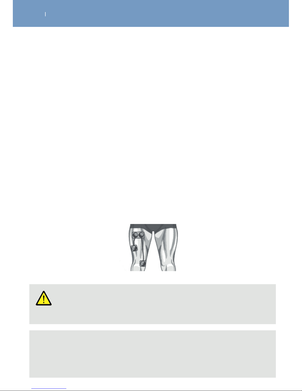
. TREATMENT OPTIONS, FUNCTIONS AND DEVICE SETTINGS
EN
WIRELESS PROFESSIONAL
Locating the motor point with the Wireless Professional:
e.g.: locating the motor point of the vastus medialis of the quadriceps
1. Apply a large electrode at the top of the thigh (the muscle belly).
2. Connect the negative pod of the module (pod without illuminated button) to the snap pin of the large
electrode located towards the inner surface of the thigh.
3. Spread a thin but even layer of conductive gel over the inner surface of the thigh in the position
indicated for the positive electrode position (the motor point area), spreading the gel a few extra
centimetres in all directions.
4. Connect the positive pod of the module (pod with illuminated button) to the snap connection of the
motorpoint pen and bring the tip of the pen in contact with the conductive gel.
5. Switch on the remote control, select the Motor point programme (program category: Rehabilitation),
then switch on the module and start the programme.
6. Very gradually increase the energy of channel 1, until a value between 5 and 25 is reached, while
continuously moving the pen tip over the gel layer, but without ever losing contact with the gel, to
avoid triggering an electrode fault message.
7. As soon as you observe a muscle response in form of twitching, you have located the vastus medialis
motor point. Visually locate this motor point and apply a small electrode that should be centred over the
motor point.
8. Remove the pen from the positive pod and connect the positive pod to the small electrode, which
should be correctly centred over the motor point of the vastus medialis.
Warning!
Patient hazard - patient contamination
Before each use of the Motor Point Pen, clean and disinfect the pen, expecially the tip that
comes into contact with the patients skin.
Note
While using the pen, it might lose contact with the skin coated in gel (even if this is just for a fraction
of a second). In this case, the stimulation will be interrupted and the equipment will signal an
electrode fault. In such a case, ignore the message, put the tip of the pen back in contact with the
skin and gradually increase the energy while moving the pen over the gel layer.
Page 50
. TREATMENT OPTIONS, FUNCTIONS AND DEVICE SETTINGS
EN
WIRELESS PROFESSIONAL
6.2 Treatment Options – Muscle Intelligence™ Technology
mi-SCAN (automatic):
Manual selection:
Just before starting a session of neuro-muscular electrostimulation, mi-SCAN analyses the characteristics
of excitability in the muscle subjected to stimulation.
mi-SCAN detects the chronaxy of the muscle in approximately 10 seconds, by detecting when and how
strong a mucle contracts while getting dierent intensitys applied. It allows the stimulator to adjust
the width (duration) of the pulse to the measured chronaxy value. Using a width (duration) of the pulse
corresponding to the chronaxy of the stimulated muscle allows the use of the minimum power to obtain
the same muscle response. As soon as the mi-SCAN function is activated each active channel performs the
chronaxy measurement.
Where recommended, this function is automatically activated, but can be deactivated and the selection of
the body part can be done manually.
6.2.1 Selection of the body area
If the mode for the manual selection of the body area is activated, the user must manually select the area
to be treated. An average chronaxy value is used based on the area selected by the user. This choice is
made after selecting the desired programme.
Page 51
. TREATMENT OPTIONS, FUNCTIONS AND DEVICE SETTINGS
EN
WIRELESS PROFESSIONAL
6.2.2 Energy management
mi-RANGE:
This function indicates the minimum energy threshold for programmes whose eectiveness requires
obtaining vigorous muscular twitches. The mi-RANGE function is therefore only available for programmes
using low stimulation frequencies (below 10 Hz).
For programmes that allow the mi-RANGE function, the stimulator first prompts you to increase the
energy level:
• A beep will accompany the flashing “+” symbols.
• When a muscle pumping is first detected, the “+” symbols stop flashing.
• You are at the minimum energy level to provide therapeutic results.
• If you set the stimulation energy below the ideal range of treatment, the stimulator prompts you to raise
them again by continuously flashing + signs.
Where recommended, this function is automatically activated.
mi-TENS:
The mi-TENS function can reduce the appearance of unwanted muscular contractions (e.g. at TENS GateControl programs), thus providing maximum comfort and eciency.
Short tests are performed regularly throughout the duration of the programme.
A testing phase takes place systematically after each increase in stimulation intensity. In order to allow its
smooth progress it is essential to remain perfectly still during this time.
According to the test results recorded by the device, the level of stimulation intensities may be slightly
decreased automatically.
Where recommended, this function is automatically activated, but can be deactivated.
Page 52
. TREATMENT OPTIONS, FUNCTIONS AND DEVICE SETTINGS
EN
WIRELESS PROFESSIONAL
mi-ACTION (voluntary):
6.2.3 Triggering of contraction
In default set up, all trigger functions are deactivated, but can be activated where available.
This is a way of working in which voluntary active muscle contraction triggers an electrical stimulation.
Contraction by electrostimulation is perfectly controlled by voluntary triggering of muscle contraction.
From the perspective of maximum eciency, the mi-ACTION working mode requires good muscular
qualities. Underperforming muscles may, in some cases, impede the onset of electrically induced
contraction.
Programmes used in the mi-ACTION mode have undeniable advantages:
• They require active participation and encourage the patient to engage fully in his or her treatment.
• They give the patient the free choice of triggering a contraction, making the practice of
electrostimulation more comfortable.
• They ensure even more eective work as they combine voluntary exercises and electrostimulation that
together allow for greater recruitment of muscle fibres.
• They promote the restoration of the body map and motor relearning in patients with impaired
neuromuscular control.
• They allow the stimulation of stabilising muscles to be integrated during an overall functional movement.
How it works:
The mi-ACTION mode is active during muscle work sequences (it is not operational during sequences of
warm-up and relaxation).
The first muscle contraction of the work sequence starts automatically.
At the end of the first contraction an active rest phase begins, characterised by muscular twitches.
The voluntary triggering of a new contraction is only possible after a minimum rest period, which varies
depending on the programme.
As soon as the voluntary triggering of a contraction is possible, the device emits a beep to inform the user.
Once the user hears the first sound signal composed of a beep, the triggering of voluntary contraction is
possible.
If no voluntary contraction has occurred after a certain period of time, the unit will automatically pause.
To work properly, the mi-ACTION needs a good muscular twitches during the active rest phase.
Page 53
. TREATMENT OPTIONS, FUNCTIONS AND DEVICE SETTINGS
EN
WIRELESS PROFESSIONAL
If the twitches are not significant enough, the unit beeps and a + sign appears on channels: you must
increase the stimulation energy to get good twitching.
Similarly, in order to make these twitches possible, it is imperative that the muscles are properly relaxed
during the resting phase.
Care should be taken at the end of each contraction phase to get back into a position allowing the best
muscle relaxation.
Trigger ON (Manual triggering - Automatic stop):
It is an operating mode in which the contraction from electrostimulation is triggered by the user by
pressing any button on any channel (4 multifunction buttons) on the remote control.
Contraction will stop automatically at the end of the time set by the programme.
The Trigger ON mode is active during muscle work sequences (it is not operational during sequences of
warm-up and relaxation).
Page 54
. TREATMENT OPTIONS, FUNCTIONS AND DEVICE SETTINGS
EN
WIRELESS PROFESSIONAL
6.3 Available Functions
6.3.1 The Favourite List
For a fast and easy access to the most frequently used programs, they can be added to the program
category “Favourites”.
It is possible to add a maximum of 10 programs to the list.
To add a program to the Favourite list, please press the multifunction button below the icon
while program is marked.
The Favorite symbole will be shown below the program while it is marked in the regular program category
and the symbole above the corresponding multifunctional button will change to the symbol
for removing the program from the favorite list.
Press the button while the symbol is shown, to remove the program from the Favorite list.
Page 55
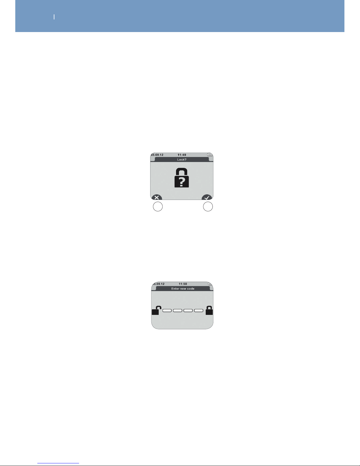
. TREATMENT OPTIONS, FUNCTIONS AND DEVICE SETTINGS
EN
WIRELESS PROFESSIONAL
6.3.2 The Lock Out function
The Lock Out function can be basically activated and deactivated within the menu for the Settings at the
Remote Control.
If basically activated:
The Remote Control will ask before each treatment whether the lock out function shall be active for this
treatment or not.
A Deactivation of the Lock function
B Activation of the Lock function
A B
Afterwards you will be asked to enter a code.
To enter the code you just need to press a combination of any four buttons.
Page 56

. TREATMENT OPTIONS, FUNCTIONS AND DEVICE SETTINGS
EN
WIRELESS PROFESSIONAL
If enabled, the function allows you to lock the device in a certain configuration before giving it to the
patient.
When the function is active the patient can perform only the basic operations:
• increase or decrease the intensity,
• pause the device
• but he or she cannot exit the programme or turn o the device.
To deactivate the Lock Out function during the treatment, pause the device and then hold down the On/
O button on the Remote Control until the display prompts you to insert your key combination to unlock
the programme.
If you have forgotten the code just put the remote control on the charging station to unlock.
Page 57
. TREATMENT OPTIONS, FUNCTIONS AND DEVICE SETTINGS
EN
WIRELESS PROFESSIONAL
6.3.3 The Synchronisation Signal
Synchronisation signal:
This function allows you to notify the user by means of a sound signal of the beginning of a muscle
contraction.
Before each contraction by electrostimulation the remote control emits beeps.
This function is only available for programmes inducing powerful muscular contractions and is functional
only during the muscular work sequence (contraction - active rest).
It can be activated within the program option menu for each corresponding program.
Page 58
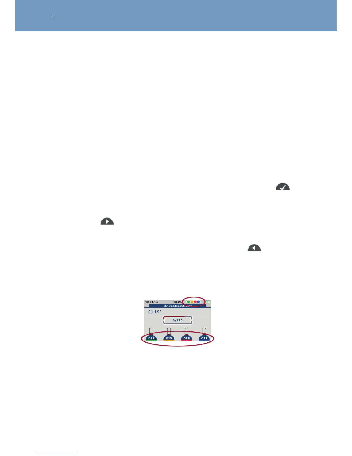
. TREATMENT OPTIONS, FUNCTIONS AND DEVICE SETTINGS
EN
WIRELESS PROFESSIONAL
6.3.4 Identify modules
The identify modules function allows you to allocate dierent colors to the dierent modules for an easier
identification of the channels during usage.
It can be activated and deactivated within the menu for the Settings at the Remote Control. Default
setting is: deactivated
To activate the function:
1. Select the function within the Settings menu of the Remote Control and press the center button. You
will be asked to turn ON ONE module.
2. Turn one the one of the modules you want to advice a color to.
3. Use the left and right arrows to select a color for this channel. The following colors are available: none/
red/green/blue/yellow
4. Allocate the chosen color to the activated module by pressing the confirmation button .
The screen will show a green hook when allocation was successfull.
5. Take the reflecting colored clip to this channel and clip it onto the cable of the module (remark: the best
positioning is close to the module with the on/o button).
6. Press the next button to proceed with the process.
7. You will be asked to turn On ONE module again.
8. To allocate colors to more channels, please follow step 2 until 6 for each reflecting module.
9. When you finished the channel identification settings, press the back button to return to device
settings.
When turning on a module and during the treatment, the screen will now show the reflecting color below
its intensity setting bar and in the header of the screen, in the order they had been turned on.
To deactivate the function again, please follow the steps 1 through 9 again, and set all modules to color:
none.
Page 59

. TREATMENT OPTIONS, FUNCTIONS AND DEVICE SETTINGS
EN
WIRELESS PROFESSIONAL
6.4 Available device Settings
Back light intensity:
The backlight intensity can be set in 5%-steps from 10% up until 100%.
Default setting: 100%
Buzzer volume:
The buzzer volume can be set in 10%-steps from 0% (= o) to 100%.
Default setting: 100%
Backlight dimmer:
The back light dimmer reduces the backlight after the set seconds of time.
Possible settings are: 15s, 30s, 60s or “o”
Default setting: 60s
Eco mode:
The eco mode can be turned on or o, while activated (on) the
Default setting: o
Lock function:
The lock out function can be activated (on) or deactivated (o).
Default setting: o
Language:
The language set up allows you to change the language setting of the Remote Control.
Default setting: English
Set time:
The set time function allows you to change the time displayed within the header of the screen.
Identify modules:
The identify modules function allows you to allocate dierent colors to the dierent modules for an easier
identification of the channels during usage.
Default setting: o
Date:
The set time function allows you to change the date displayed within the header of the screen.
System info:
The system info provides information regarding the serial number and the software of the Remote
Control.
Page 60

. TREATMENT OPTIONS, FUNCTIONS AND DEVICE SETTINGS
EN
WIRELESS PROFESSIONAL
Pairing of new module:
The pairing of new module function enables you to add a new module to the Remote Control (usually
done automatically by the unit). 1 up 4 modules can be operated max with one Remote Control.
Rest to factury setting:
This function activated, resets the Remote Control to the default setting. All data stored on the remote
control, incl. Device settings, favourites, history etc. will be automatically deleted.
Page 61

. TREATMENT OPTIONS, FUNCTIONS AND DEVICE SETTINGS
EN
WIRELESS PROFESSIONAL
6.5 WIRELESS PROFESSIONAL SOFTWARE (firmware update remote control,
customised programs, patient history)
The WIRELESS PROFESSIONAL SOFTWARE is a software to be installed on your Computer to extend the
capabilities of your WIRELESS PROFESSIONAL 2 and 4CH devices.
The key features included with the SOFTWARE are:
• Update the firmware of your WIRELESS PROFESSIONAL remote Control
• Create your own customized stimulation programs
• Create a patient list and monitor their therapy progress
You can download the SOFTWARE to your computer from
http://international.chattgroup.com/products/wireless-professional/
6.5.1 Firmware update of the Remote Control
The WIRELESS PROFESSIONAL SOFTWARE always contains the latest version of the WIRELESS
PROFESSIONAL firmware of the remote control and modules.
To update your Remote Control:
1. Download the SOFTWARE from
http://international.chattgroup.com/products/wireless-professional/
2. Run the SOFTWARE
3. Connect your Remote Control to your Computer
The firmware of your remote control will be automaticly updated by the SOFTWARE.
Your modules will be automatically updated by the Remote Control when turning them on within the next
treatment session.
Page 62
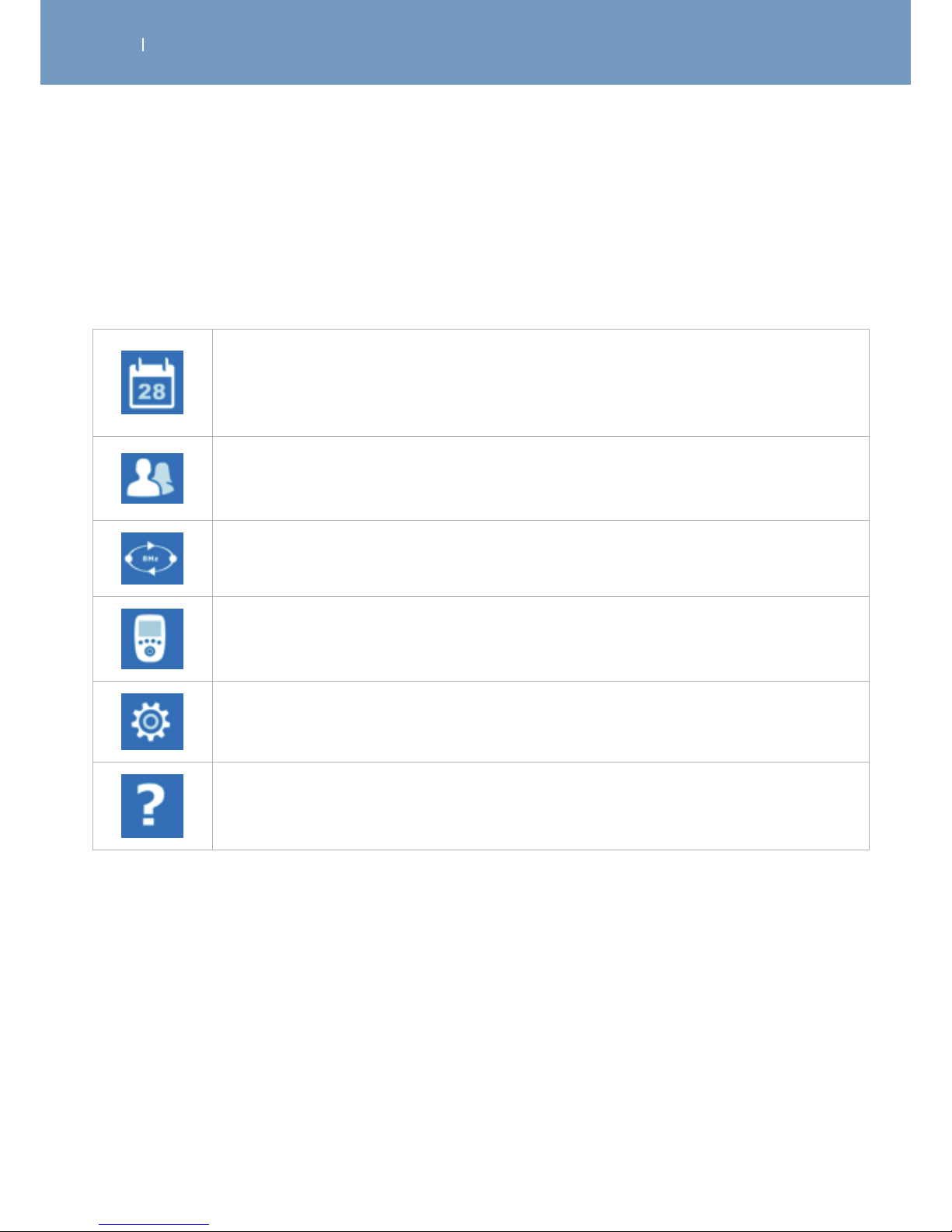
. TREATMENT OPTIONS, FUNCTIONS AND DEVICE SETTINGS
EN
WIRELESS PROFESSIONAL
6.5.2 Additional Functions of the SOFTWARE, when having a WIRELESS
PROFESSIONAL device
When having a WIRELESS PROFESSIONAL device the SOFTWARE allows you additional functions to be
used with your Remote Control.
History List:
When having the Remote Control synchonised with your Computer, all performed
treatments will be shown in this list in the order they had been performed, the latest
first.
Patient List:
Will show all patients you added to this list, the notes you made on them and the
history of their treatments.
User Program List:
Will show all programs you created an their parameters.
Synchronisation:
To synchronise the Remote Control and the SOFTWARE
Settings:
For database and application configuration.
Help:
You will find instructions to use the SOFTWARE and warnings in here.
Page 63
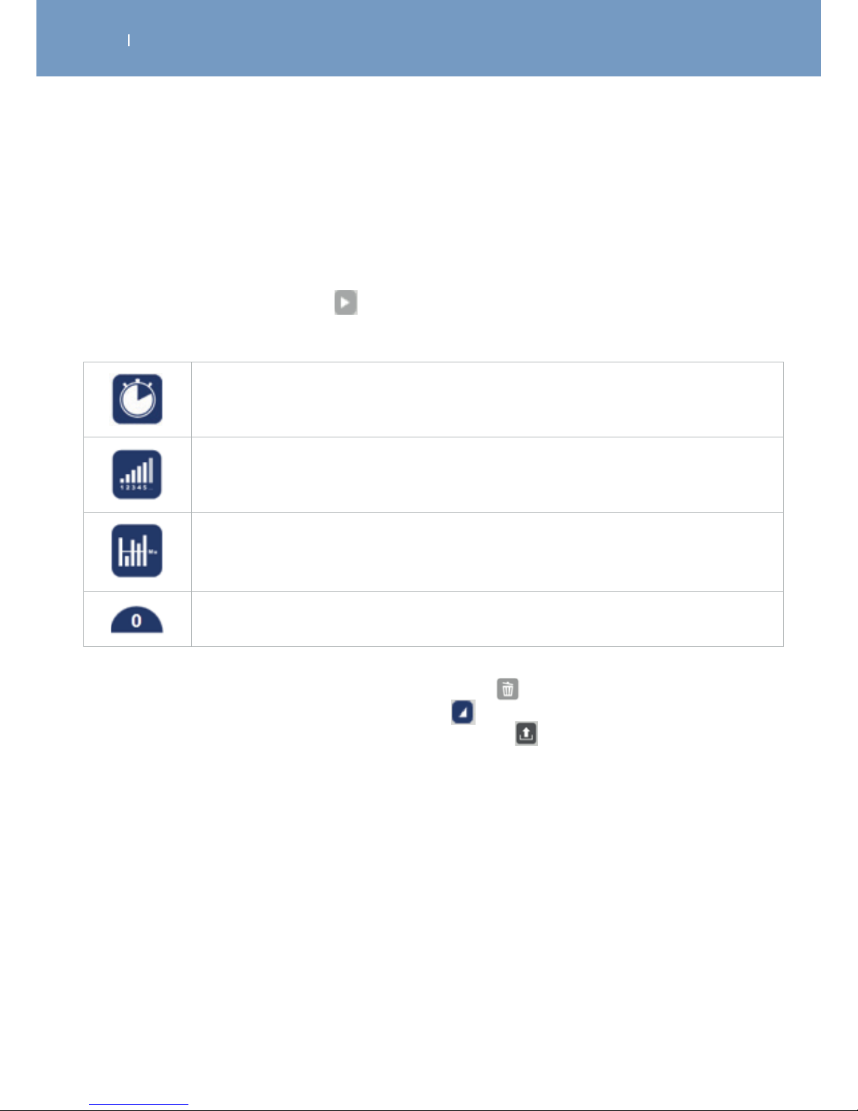
. TREATMENT OPTIONS, FUNCTIONS AND DEVICE SETTINGS
EN
WIRELESS PROFESSIONAL
6.5.2.1 History list
When having the Remote Control synchonised with your Computer, all performed treatments will be
shown in this list in the order they had been performed, including date, time, patient name (if it was
assigned to a patient from the patient list) and program name, the latest first.
When clicking on the extend symbol of a session, the session details will be shown.
Session details are:
Treatment time
Number of contractions
Average intensity of all channels used
Maximum intensity per channel
You can delete a session from the list by clicking on the delete button.
You can close the details view by clicking on the reduct button.
You can export the list into an Excel file, by clicking on the export button. The SOFTWARE will
automatically suggest a name for that file and ask for the location it should be stored to.
Page 64
. TREATMENT OPTIONS, FUNCTIONS AND DEVICE SETTINGS
EN
WIRELESS PROFESSIONAL
6.5.2.2 Create a patient’s list and monitor their treatment progress
The Patient list will show all patients you added to this list, the notes you made on them and the history of
their treatments (automatically transferred from the History List).
To add a patient to the list:
1. Click on the Add button
2. Fill the requested fields for the patient’s personal data. The fields Name, Surname and Pseudonyme are
mandatory. The field Pseudonyme will be filled automatically, but can be changed after.
3. Add Pathology information of notes, if wanted
4. Click on the confirmation/store button. The button appears as soon as the mandatory fields had
been filled.
The patient will be automatically shown within the patient list.
If you don’t want to store the data, click on the back button, to return to the patient list. All inserted
data will be deleted.
Within the patient list you can:
• Select a patient by clicking on the name.
• Edit/Change the patient’s data by clicking on the edit button.
• Export the patient history list into an Excel file, by clicking on the export button. The SOFTWARE will
automatically suggest a name for that file and ask for the location it should be stored to.
• Delete a patient from the list by clicking on the delete button.
• View details on each treatment of the patient by clicking on the extend button and reduce the
details view by clicking on the reduce button. (see as well History List)
• Mark a patient to be synchronised and become available with your remote control. If you don’t want
the patient to be synchronised with your remote control, click on the hook button to remove the
hook from the field.
Default setting: synchronisation on
When patients had been added to the patient list and synchronised with the remote control, your
WIRELESS PROFESSIONAL will ask you after each treatment session to add the last treatment to a patient
from your patient list.
To do so:
• Press the next or the center button when the treatment time elapsed
• The patient list will be displayed automatically. Select a patient by using the up/down buttons.
• Confirm by using the confirmation button or the center button
If you don’t want to assign this treatment to a patient of your list, just press the return button to
return to the available programs and program category.
The treatment will become visible within the history list and the patient list when synchronising the
remote control with your computer the next time.
Page 65
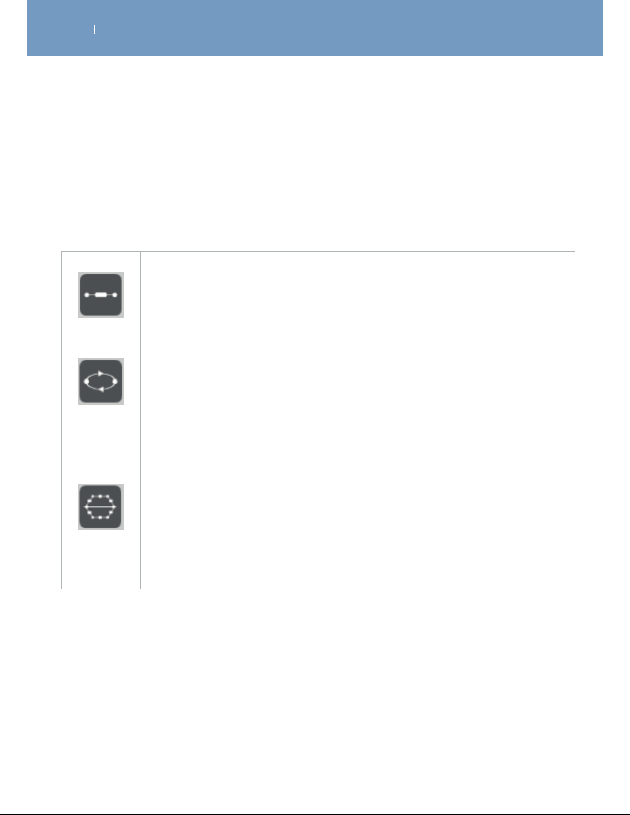
. TREATMENT OPTIONS, FUNCTIONS AND DEVICE SETTINGS
EN
WIRELESS PROFESSIONAL
6.5.2.3 Create customized stimulation programs
When having a WIRELESS PROFESSIONAL the SOFTWARE allows you to create your own stimulation
programs.
It is possible to adjust the treatment parameters and create your own stimulation programs, based on the
following program architectures:
Continuous Programs
Adjustable parameters:
• Impulse width
• Treatment session length
• Frequency
Modulated Programs
Adjustable parameters:
• Treatment session length
• Frequency
• Impulse width
Work/Relax Programs
Adjustable parameters:
• Impulse width
• Treatment session length
• Warm up / Cool down (on/o)
And for the Work and Relax phases separately
• Frequency
• Duration
• Ramp up duration
• Ramp down duration
Values of the adjustable parameters:
Treatment session length: 1 – 240 minutes
Impuls width: 30 – 400 µs
Frequency: 1 – 150 Hz (at Work/Relax: 0 – 20 Hz for the Relax phase)
Ramp-up duration: 0.25 – 10 seconds
Ramp-down duration: 0 – 2 seconds at Work and 0.25 – 2 seconds at Relax
Duration: 0.25 – 60 seconds
Warm-up/Cool down: On/O
Note: when activating the warm-up/cool down function, the program will
automatically add 5 minutes for warm-up and 10 minutes for cool down to
your set treatment time.
Page 66
. TREATMENT OPTIONS, FUNCTIONS AND DEVICE SETTINGS
EN
WIRELESS PROFESSIONAL
To create your own treatment program the first time:
1. Click on Program
2. Click on the architecture symbol your program is selected to have
3. Enter a name for the program (mandatory) and notes (optional)
4. Adjust the parameter, by clicking on the parameter and changing the values with the + and – buttons
on the screen.
5. Store the program by clicking on the green hook button . This button will be displayed as soon as
the mandatory field had been filled.
Your new programs will be shown in the “user program list”.
If you don’t want to store the program, click on the back button, to return to the program list. All
inserted data will be deleted.
The User Program List will show all your created programs.
Within the Program List you can:
• Select a program by clicking on the name. When clicking on it, all set parameter and the architecture of
the program will be shown.
• Edit/Change the program parameter and notes by clicking on the edit button.
• Export the program parameters into an WIRELESS PROFESSIONAL SOFTWARE file, by clicking on
the export button. The SOFTWARE will automatically suggest a name for that file and ask for
the location it should be stored to. This feature allows you to share it with any other Computer the
SOFTWARE is installed on.
• Delete a program from the list by clicking on the delete button.
• Mark a program to be synchronised and become available with your remote control. If you don’t
want the program to be synchronised with your remote control, click on the hook button to remove the
hook from the field.
Default setting: synchronisation on
Page 67

. TREATMENT OPTIONS, FUNCTIONS AND DEVICE SETTINGS
EN
WIRELESS PROFESSIONAL
All programs that had been synchronised with your Remote Control, will be shown in a separate program
category called “Personalised Programs”.
Please note:
• Programs from the Personalised Programs category list cannot be added to the Favorite program
category.
• Mi functions will not be available for customised programs
• Dierent treatment options to be turned on or o, will be available for the 3 dierent program
architectures:
- Modulated Programs: none
- Continuous Programs: Bodyzone selection
- Work/Relax Programs: Bodyzone Selection, Synchronisation Signal and Triggering of contraction
(please note, apart from the regular trigger function, the stimulation will only last as long as the trigger
button will be pressed)
• The information showen in relation to a program will be the information/notice entered within a
program at the SOFTWARE (if there is one) and the set program parameters.
• When selecting a program, the remote will not automatically ask you to turn on the Modules and start
the treatment. For customized programs, the architecture and parameters of this customised program
will be displayed first. You can confirm that this is the parameters you want to treat the patient with by
pressing START and the remote control will ask you to turn on the Modules afterwards.
Page 68

. TREATMENT OPTIONS, FUNCTIONS AND DEVICE SETTINGS
EN
WIRELESS PROFESSIONAL
6.5.2.4 Remote Synchronisation
During the synchronisation process, selected custom programs will be automatically transferred to your
device and will be available under the “Personalised Programs” category. Likewise, the patient’s list will also
be transferred to your device, and will allow assigning stimulation sessions to a particular patient.
During this process, stimulation session’s history stored on your Wireless Professional device will also be
transferred to the software.
The screen will show a symbole for your computer and the Remote Control, connetected by a line.
• If there is no remote connected, the line will be interrupted by a red X.
• If there is a remote connected to the computer, the Synchronisation symbole will interrupt the line.
To synchronise, click on the synchronisation symbole. The circle on it will start turning while the
synchronisation is in process.
Please do not disconnect your remote control from your computer during the synchronisation process, or
the process will fail.
Page 69

. TREATMENT OPTIONS, FUNCTIONS AND DEVICE SETTINGS
EN
WIRELESS PROFESSIONAL
6.5.2.5 Configuration/Settings
Within the Configuration/Setting menu, it is possible to change the application configuration by selecting
dierent languages.
The following languages are available:
• English
• French
• German
• Spanish
• Italian
• Dutch
• Turkish
• Portuguese
• Danish
• Swedish
• Norwegian
• Finnish
• Czech
• Russian
• Polish
• Greek
It is as well possible to manage your data base with the following functions:
1. Backup / Restore your data:
The database administration tab allows you to backup all your data (history, patient’s list and custom
programs) in a file that can be saved on any storage system. Just click on “backup” and the SOFTWARE will
automatically suggest a name for the backup file and ask you where you want to store it.
If necessary, this backup file can then be used to Restore your data.
Just click on “Restore”, select the file you want to use to restore your system and confirm.
2. Clear all data
Clicking on “Clear all data” will delete all stored data within the SOFTWARE and reset the SOFTWARE to
the default setting.
And the information about the SOFTWARE is included:
• Disclaimer
• Version
• Contact
Page 70

. TREATMENT OPTIONS, FUNCTIONS AND DEVICE SETTINGS
EN
WIRELESS PROFESSIONAL
6.5.2.6 Help
The Help tap contains a summary of all information required to use the SOFTWARE, including the
warnings.
Page 71
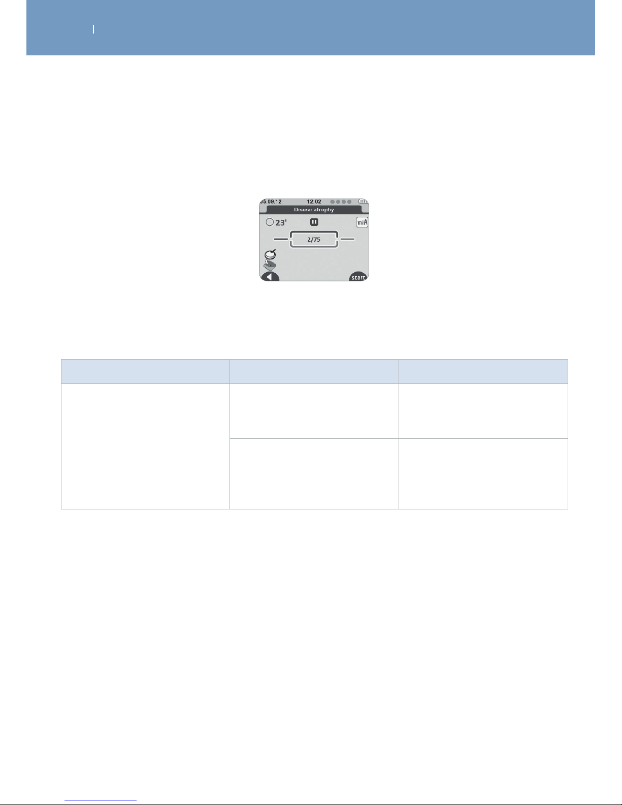
. TROUBLESHOOTING
EN
WIRELESS PROFESSIONAL
7.1 Errors shown on display
Problem Possible cause Solution
Electrode failure
Poor electrode connection to the
module
Check that the electrodes are
properly connected to the
module.
Poor electrode connection to the
skin
Check if the electrodes are
outdated, worn and/or the
contact is poor: try with new
electrodes.
The remote control shows the symbol of an electrode and a disconnected module.
Shown on the channel where the problem was detected (in this case channel 1):
Poor electrode/module contact
Page 72
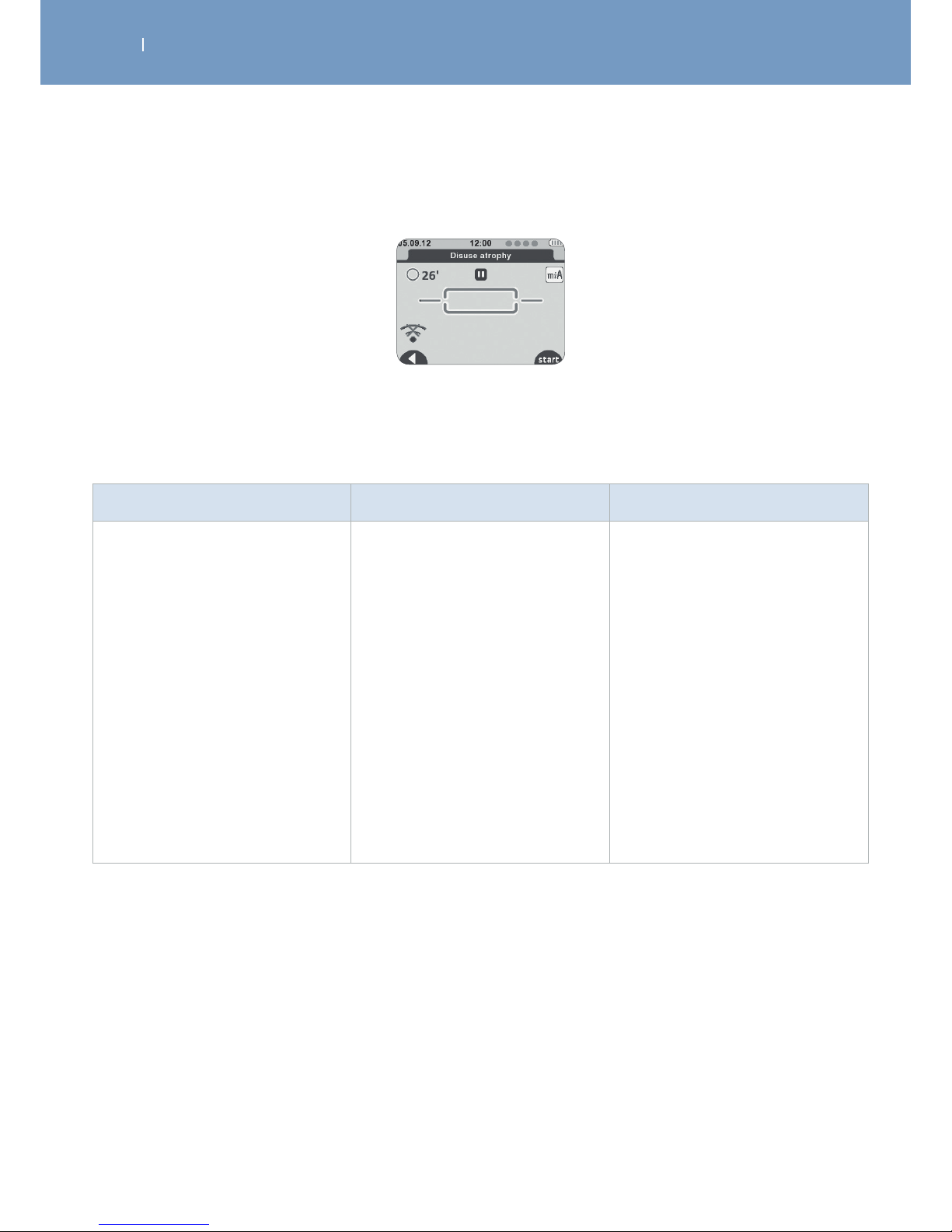
. TROUBLESHOOTING
EN
WIRELESS PROFESSIONAL
Modules out of range
The remote control shows the out of range symbol. Shown on the channel where the problem was
detected (in this case channel 1):
Problem Possible cause Solution
No connection with modules
Modules are out of range from
Remote Control
A. Check that the module and
the remote control are less
than 2 metres away.
B. Ensure you are not in an
isolated place, without any
obstacles that may deflect
the signals from the remote
control.
C. Ensure you are in a place
that allows the signal from
the remote control to be
reflected.
D. Check the module is switched
on.
Page 73
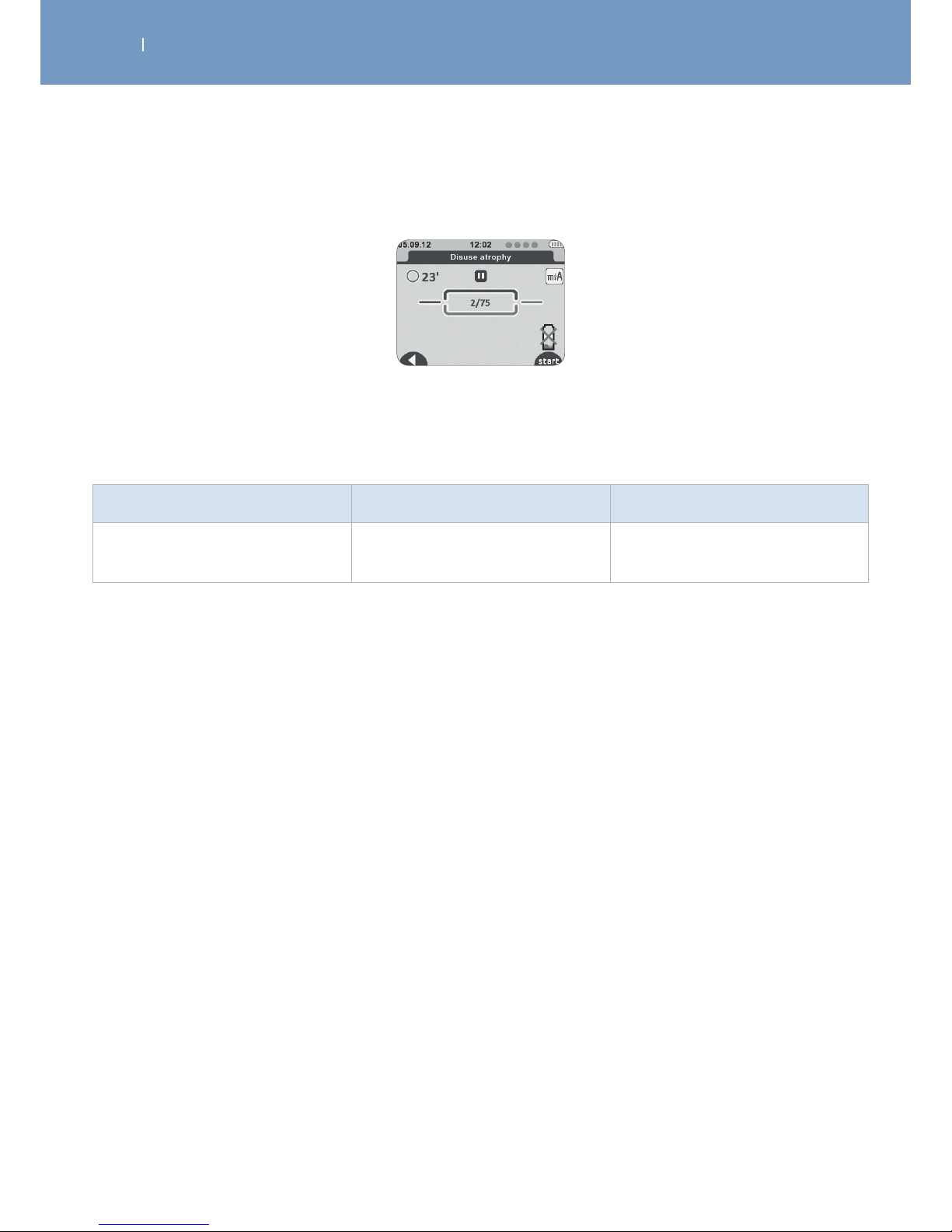
. TROUBLESHOOTING
EN
WIRELESS PROFESSIONAL
Battery level
Problem Possible cause Solution
Module battery low
During the stimulation a module
may turn out to be discharged.
Stop the stimulation and
recharge the discharged module.
The remote control shows a discharged battery symbol. Shown on the channel where the problem was
detected (in this case channel 4):
Page 74

. TROUBLESHOOTING
EN
WIRELESS PROFESSIONAL
7.2 Behaviour of the Module LEDs
Problem Possible cause Solution
The LED blinks alternately green
and red
The module is out of range or is
not recognised by the Remote
Control.
A. Check the remote control is
properly turned on.
B. Check that the module and
the remote control are less
than 2 metres away.
C. Try restarting the module.
D. Place the module and the
remote control on the same
docking station in order to
pair them.
The LED is constantly red Module battery level low
A. Check the module is charged.
B. Try restarting the module.
C. If despite this the LED is still
red, contact the customer
services that have been
stipulated and approved by
the manufacturer.
Page 75

. TROUBLESHOOTING
EN
WIRELESS PROFESSIONAL
7.3 Behaviour of the Docking Station LEDs
Problem Possible cause Solution
The docking station’s central LED
lights red
Modules can’t be charged due to
no connection to tablet or main
power.
A. Ensure that the modules
are properly placed in their
housing.
B. Ensure the charging contacts
are clean.
C. Ensure the correct AC adapter
is used.
D. Disconnect and reconnect
the docking station and
check the lighting sequence
of the docking station upon
activation.
• Remove all modules.
• Remove the remote control.
• Disconnect the USB cable.
If despite this the LED is still red,
contact the customer services
that have been stipulated and
approved by the manufacturer.
Page 76
. TROUBLESHOOTING
EN
WIRELESS PROFESSIONAL
7.4 Others
Problem Possible cause Solution
The stimulator is not working
Device not answering
If the remote control is ON, but
does not respond to pressing the
key pad buttons:
A. Press the ON/OFF button for
2 seconds to turn the device
OFF
B. Wait 10 seconds.
C. Turn Remote Control ON
again
Low batteries
Ensure the remote control and
the modules are charged. When
the batteries are completely
discharged, charging for a few
minutes may be required before
the unit turns on.
A. Try to restart the remote
control and modules.
B. Place the module and the
remote control on the same
docking station in order to
pair them.
C. If, despite this, the device is
still not working, contact the
customer services that have
been stipulated and approved
by the manufacturer.
Bad connections
If the device is on, the intensity
bar graphs and controls are on,
and you feel no stimulation,
check and verify the connection
of the electrodes
Lead wire or electrode defective
If the device appears to be
functioning, and there is no
stimulation, replace the lead
wires and/or electrodes
Page 77

. TROUBLESHOOTING
EN
WIRELESS PROFESSIONAL
Problem Possible cause Solution
Display does not come on Low batteries Load batteries
Weak stimulation with loaded
batteries
Electrodes dried out, lost their
adhesive power and have no
adequate connection to th skin.
Replace electrode
Electrode placement
Make the electrodes at least 2”
apart
Stimulation stops with loaded
batteries
Poor electrode contact
Reapply electrodes, secure firmly.
Electrodes must be a minimum
of 2 inches apart.
Damaged or worn electrodes or
module leadwires
Replace.
Stimulation weakens within
minutes of starting treatment
with loaded batteries
This is a normal body adaptive
process
Increase the amplitude
(intensity) if required.
Stimulation is uncomfortable
Amplitude (intensity) is too high Decrease amplitude (intensity).
Electrodes are too close together
Reposition the electrodes.
Electrodes must be a minimum
of 2 inches apart.
Damaged or worn electrodes or
leadwires of modules
Replace.
Ensure proper program is being
used
A. Refer to section 6.1 and 7 for a
description of the Programs
B. Contact clinician if discomfort
persists.
Stimulation is ineective
Improper electrode placement
Reposition electrodes. Electrodes
must be a minimum of 2 inches
apart.
Unknown Contact clinician.
Stimulation only felt on one
electrode
Improper electrode placement
A. Reposition electrodes.
Electrodes must be a
minimum of 2 inches apart.
B. Replace electrodes.
Page 78

. TROUBLESHOOTING
EN
WIRELESS PROFESSIONAL
Problem Possible cause Solution
Stimulation on one channel
(side) only
Electrodes
A. Worn or damaged
B. Improper placement
Leadwires among modules worn
or damaged
A. Replace.
B. Reposition electrode.
Electrodes must be a
minimum of 2 inches apart.
Replace
Intermittent Output Intermittent program in use
Some programs will seem
intermittent. This is expected.
Refer to section 6.1 for a
description of the Programs.
Stimulation is not producing the
usual sensation
Settings and Electrodes
positioning
A. Check that all the settings
are correct and ensure the
electrodes are positioned
properly.
B. Change the positioning of the
electrodes slightly.
Remote Control is not loading
USB cable of docking station not
connected to Tablet
Check connections
Power cord of Tablet not
connected to mains
Modules are not loading
Power cord of Tablet not
connected to mains
Check connections
Modules not placed the right
way
Check module placement in
Tablet
Page 79
. CARE, MAINTENANCE, TRANSPORT, ENVIROMENTAL STATEMENT
EN
WIRELESS PROFESSIONAL
8.1 Care
Warning!
Shock hazard - Remove the power cord of the Tablet from the wall outlet before cleaning.
Shock hazard, equipment damage -
- Liquids must not enter the device and it’s components, incl. the Tablet. If liquids have
entered into the components, the Wireless Professional must be immediately checked by
a service technician, before it can be reused.
- Never dismantle the remote control, the modules, the docking station or the AC adapter
as they contain high-voltage parts with a risk of electric shock.
Warning!
Patient hazard - patient contamination
- Before using the unit on another patient, clean and disinfect it according to the
instructions in this section.
Caution!
Equipment damage -
- The plastic material used is not resistant to mineral acids, formic acid, phenols, cresols,
oxidants and strong organic or inorganic acids with a pH value below 4.
- Use only clear disinfectants to prevent discoloration of the device.
- Do not expose the therapy unit to strong ultraviolet radiation (sunlight) and fire.
- Do not sterilize the stimulator.
- Do not immerse in liquids.
• All parts of the Wireless Professional can be disinfected by wiping down with a disinfectant. Thus, it
complies with the special hygiene standards for medical technical equipment.
• All components can be cleaned with common disinfectants and mild household detergents.
• Only use a soft cloth and an alcohol-based, solvent-free cleaning product, to wipe the therapy unit
down.
• Allow the device to completely dry before use.
Page 80
. CARE, MAINTENANCE, TRANSPORT, ENVIROMENTAL STATEMENT
EN
WIRELESS PROFESSIONAL
Warning!
Shock hazard, Equipment damage Do not attempt to repair the stimulator or any of its accessories. Never dismantle the
device because of risk of electric shock. DJO Global declines all responsibilities for any
damages or consequences resulting from unauthorised attempts to open, modify, or repair
the stimulator. This may only be done by persons or repair services authorized by the
manufacturer
8.2 Maintenance
Your Wireless Professional does not require calibration or frequently safety testings. Each stimulator is
tested prior to distribution. Its characteristics do not vary under normal conditions.
If your stimulator contains parts that seem worn or defective, please stop using it and contact the
customer service centre that has been stipulated and authorised by the manufacturer regarding an
upgrade.
There are no user serviceable parts inside the device. If the device appears to be non-functional, contact
DJO Global or your local dealer.
Page 81
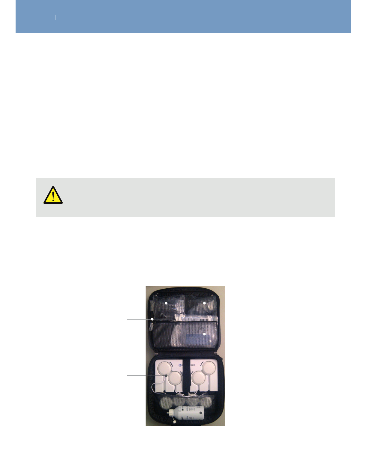
. CARE, MAINTENANCE, TRANSPORT, ENVIROMENTAL STATEMENT
EN
WIRELESS PROFESSIONAL
Caution!
Equipment damage Only use the original transport bag for carrying the device around.
8.3 Transport
8.3.1 Transport of the 4CH device key components and the Tablet
(off site treatment)
1. Prepare the device and its accessories for shipping within the original Rehab/Theta/Physio shipping box
2. Turn the device and it’s accessories o.
3. Disconnect and dismount the device and it’s accessories by following the guidelines
4. Place the accessories within the box as shown in the pictures below.
5. Store the user manual in the CD pocket of the transport bag.
1. Turn the device and it’s accessories o.
2. Disconnect and dismount the device and it’s accessories by following the guidelines but keep the
Modules in the Tablet.
3. Store the user manual in CD in the outer pocket of the transport bag.
4. Place the accessories in the transport bag as shown in picture below
Remote Control
Motor Point Pen
Tablet and Modules
AC Adaptor (power supply)
and USB connector
Electrodes
Bottle of conductive gel
Page 82
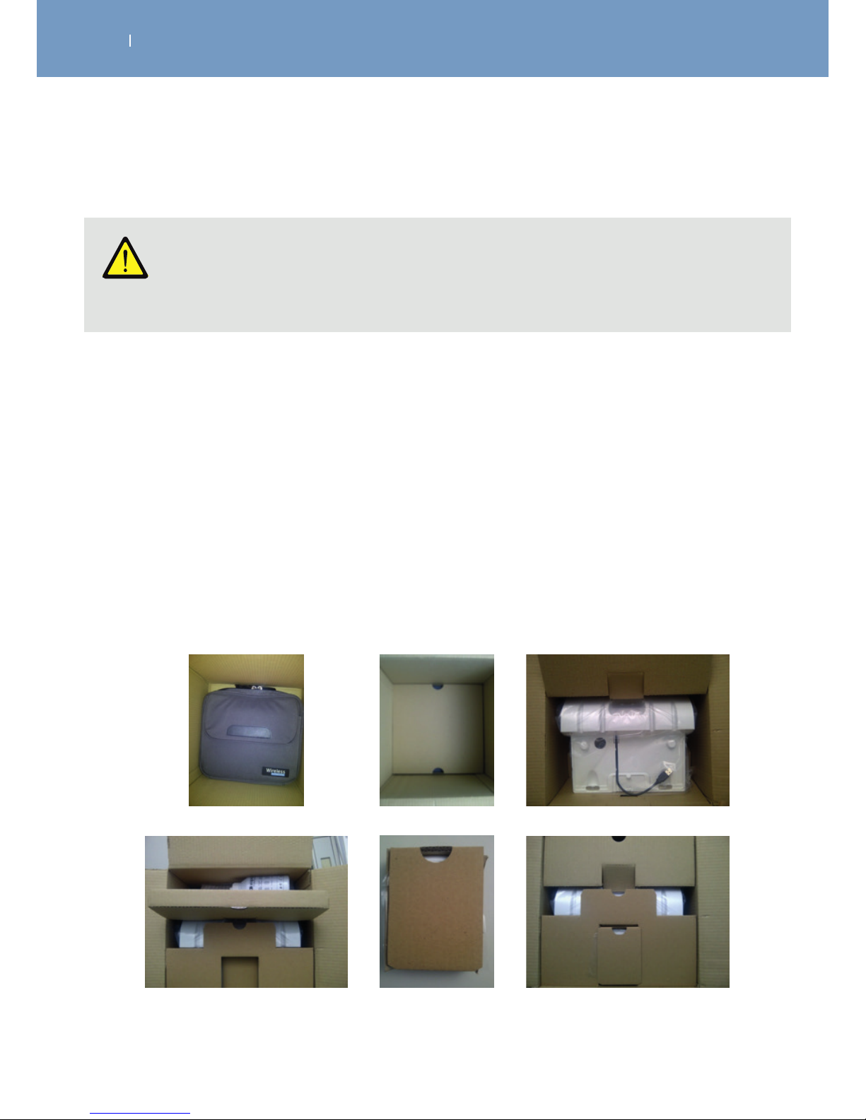
. CARE, MAINTENANCE, TRANSPORT, ENVIROMENTAL STATEMENT
EN
WIRELESS PROFESSIONAL
Caution!
Equipment damage Only use the original shipping box for shipping the device. DJO cannot be held liable for
transport damage if the device is not packed in its original shipping box.
1. Prepare the device and its components for shipping within the original Wireless Professional shipping
box, by following the guidlines given previously.
Do not place the Remote Control, the user manual and the Bottle of Conductive Gel within the
transport bag.
2. Place the components within the box like shown in the pictures below.
a. Place the transport bag at the bottom of the (paper) shipping box
b. Cover the transport bag with the paper spacer
c. Cover the Docking Station with the protective paper piece and place it in the box
d. Place the Bottle of Conductive Gel in the Box
e. Put the Remotes Control in their separate paper box
f. Place the Remotes Control Box in the slots at the surface.
g. Close the Transport Box
8.3.2 Shipping the entire 4CH unit (incl. Smart Docking Station)
a.
d.
b.
e.
c.
f.
Page 83
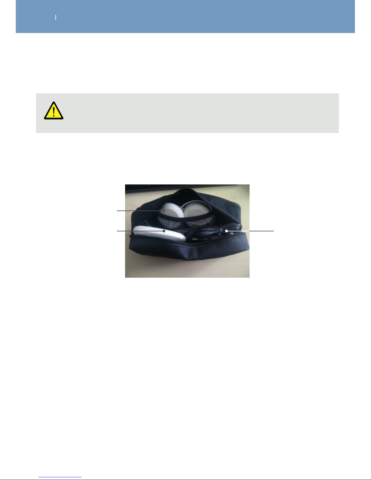
. CARE, MAINTENANCE, TRANSPORT, ENVIROMENTAL STATEMENT
EN
WIRELESS PROFESSIONAL
Caution!
Equipment damage Only use the original transport bag for carrying the device around.
8.3.3 Transport of the 2CH device key components
1. Turn the device and it’s components o.
2. Disconnect and dismount the device and it’s components by following the guidelines
3. Place the components in the transport bag as shown in picture below
Modules
Remote
AC Adaptor
(power supply)
and USB
connector
Page 84
. CARE, MAINTENANCE, TRANSPORT, ENVIROMENTAL STATEMENT
EN
WIRELESS PROFESSIONAL
Caution!
Equipment damage Only use the original shipping box for shipping the device. DJO cannot be held liable for
transport damage if the device is not packed in its original shipping box.
1. Prepare the device and its components for shipping within the original Wireless Professional shipping
box, by following the guidlines given previously.
2. Place the components within the box like shown in the pictures below.
a. Place at the bottom the electrodes and user guide on CD in the specific box
b. Cover the electrode and user guide with the paper spacer
c. Place the docking station in a specifi box and insert it in the room allowed by the paper spacer
d. Put the Remote Control and module in its separate foam box, put it into the paper spacer and cover
the docking station box. Cover the Docking Station with the protective paper peace and place it in
the box.
e. Close the Transport Box
8.3.4 Shipping the entire 2CH unit (incl. Basic Docking Station)
Page 85

. CARE, MAINTENANCE, TRANSPORT, ENVIROMENTAL STATEMENT
EN
WIRELESS PROFESSIONAL
8.4 Enviromental Statement, Expected Life
The Wireless Professional device is electronic equipment and may include substances that can damage
the environment. It must not be dispose of with unsorted household or municipal waste. It requires
separate disposal at a suitable collection point for recycling of electronic equipment. By doing so, you
will be contributing to the safeguarding of natural resources and health. Please contact DJO GLOBAL for
information about the possible recycling of the product.
When the electrodes no longer stick well to your skin, dispose of them in a receptacle out of reach of
children and pets.
The product as well as the parts and accessories supplied with it are designed for a minimum service life of
6 years of normal usage.
Page 86

. TECHNICAL DATA, STANDARDS, GUARANTEE, PATENTS
EN
WIRELESS PROFESSIONAL
9.1 Technical Data
9.1.1 General information
Model: Wireless Professional 4CH
Part number: 2532xxx
MDD: Class IIa
IP class: IP22
Applied part: Type BF
Power supplies:
Remote Control battery: Lithium polymer (LiPo) rechargeable 3.7[V] / ≥ 1500[mAh].
Module batteries: Lithium polymer (LiPo) rechargeable 3.7[V] / ≥ 450[mAh].
Tablet AC Adaptor:
Only 5 [V] / 3.5 [A] adapters with the reference number 6490xx can be
used to recharge the Wireless Professional.
Battery life:
Battery life of Remote control and Module batteries:
approx. 5 years, cannot be replaced by the user!
Model: Wireless Professional 2CH
Part number: 25326xx
MDD: Class IIa
IP class: IP22
Applied part: Type BF
Power supplies:
Remote Control battery: Lithium polymer (LiPo) rechargeable 3.7[V] / ≥ 1500[mAh].
Module batteries: Lithium polymer (LiPo) rechargeable 3.7[V] / ≥ 450[mAh].
Tablet AC Adaptor:
Only 5 [V] / 3.5 [A] adapters with the reference number 6490xx can be
used to recharge the Wireless Professional.
Battery life:
Battery life of Remote control and Module batteries:
approx. 5 years, cannot be replaced by the user!
Page 87

. TECHNICAL DATA, STANDARDS, GUARANTEE, PATENTS
EN
WIRELESS PROFESSIONAL
9.1.2 Neuro-Stimulation Parameters
All electrical specifications are given for an impedance of 500-1,000 ohms per channel.
9.1.3 RF data
The Wireless Professional may be aected by other devices even if they are compliant with CISPR
EMISSION requirements.
Outputs:
Four independent and individually adjustable channels that are
electrically isolated from each other.
Pulse shape:
Constant rectangular current with pulse compensation to eliminate
any direct current component to prevent residual polarisation at skin
level.
Maximum pulse intensity: 120 mA.
Pulse intensity increments:
Manual adjustment of stimulation intensity from 0 to 999 (energy) in
minimum increments of 0.25 mA.
Pulse width: 30 to 400 s.
Maximum electrical
charge per pulse:
96 micro coulombs (2 × 48 C, compensated)
Standard pulse ramp-up time: 3 s (20 %-80 % of maximum current)
Pulse frequency: 1 to 150 Hz.
Transmission and reception
frequency:
2.4 [GHz] ISM (2.4-2.4835 GHz)
Characteristics of the
modulation type and frequency:
GFSK, +/-320 [kHz] deviation
Eective transmission power: 4.4 [dBm]
Page 88

. TECHNICAL DATA, STANDARDS, GUARANTEE, PATENTS
EN
WIRELESS PROFESSIONAL
9.1.4 Information on electromagnetic compatibility (EMC)
The Wireless Professional is designed to be used in typical environments that have been approved in
accordance with the EMC safety standard EN 60601-1-2.
This device complies with the CISPR standard, indicating that radio frequency (RF) emissions are not likely
to cause interference with electronic equipment installed nearby (radios, computers, telephones, etc.).
The Wireless Professional is designed to withstand foreseeable disturbances from electrostatic discharge,
magnetic fields from the mains power supply or RF transmitters.
Nevertheless, it is not possible to ensure that the stimulator will not be aected by powerful RF (radio
frequency) fields from other sources.
For more detailed information concerning electromagnetic emissions and immunity, refer to the EMC
tables.
9.1.5 Enviromental conditions
Storage and Transport Conditions
The device must be stored and transported in accordance with the following conditions:
Temperature: -20° C to 45°C
Maximum relative humidity: 75%
Atmospheric pressure: 700 hPa to 1,060 hPa
Temperature: 0° C to 40° C
Maximum relative humidity: 30% to 75%
Atmospheric pressure: 700 hPa to 1,060 hPa
Conditions of use
Page 89

. TECHNICAL DATA, STANDARDS, GUARANTEE, PATENTS
EN
WIRELESS PROFESSIONAL
9.2 Standards
To guarantee your safety, the Wireless Professional has been designed, manufactured, and distributed in
compliance with the requirements of European Directive 93/42/EEC, as amended, on medical devices.
The Wireless Professional also complies with the IEC 60601-1 standard on general safety requirements for
electro-medical devices, the IEC 60601-1-2 standard on electromagnetic compatibility, and the IEC 606012-10 standard on particular safety requirements for nerve and muscle stimulators.
Current international standards require that a warning be given concerning the application of electrodes
to the thorax (increased risk of cardiac fibrillation).
The Wireless Professional also complies with Directive 2012/19/EU on waste electrical and electronic
equipment (WEEE).
9.4 Patents
The Wireless Professional incorporates several innovations with patents pending or already issued.
9.3 Guarantee
This guarantee is valid only if it is accompanied by proof of purchase.
Your statutory rights are not aected by this guarantee.
Your Wireless Professional stimulator is guaranteed for a period of 3 years from the date of purchase. The
guarantee covers the remote control, the modules, the docking station and the AC adaptor (hardware and
labour), but not the batteries, electrodes or the motor point pen.
All defects resulting from poor quality material or workmanship are covered.
This guarantee does not cover damage resulting from impact, accidents, misuse, inadequate protection
against moisture, immersion in water or repairs made by unauthorised personnel.
Page 90
. EMC TABLES
EN
WIRELESS PROFESSIONAL
10. EMC Tables
The Wireless Professional needs special EMC precautions and must be installed and started according to
the EMC information supplied in this manual.
All RF wireless transmission systems can aect the Wireless Professional.
The use of accessories, sensors and cables other than those recommended by the manufacturer may result
in stronger emissions or reduce the immunity of the Wireless Professional.
The Wireless Professional should not be used beside or stacked on top of any other equipment. If you must
use it side by side or on top of another system, you should check that the Wireless Professional works
properly in the chosen configuration
The product designation of the Wireless Professional used in the text below includes all product variants.
10.1 Electromagnetic emissions
RECOMMENDATIONS AND DECLARATION BY THE
MANUFACTURER CONCERNING ELECTROMAGNETIC EMISSIONS
The device is intended for use in the electromagnetic environment specified below.
The customer or user of the device should ensure that it is used in this environment
Emissions test Compliance Electromagnetic environment - Guide
RF emissions
CISPR 11
Group 1
The Wireless Professional uses RF energy only
for its internal operation. Consequently, its RF
emissions are unlikely to interfere with any
adjacent electrical device (radios, computers,
telephones etc.).
RF emissions
CISPR 11
Class B
Wireless Professional is suitable for use in any
establishment, other than a private dwelling or a
place connected directly to the low voltage mains
supply which powers residential buildings.
Harmonic emissions
IEC 61000-3-2
Class A
Voltage fluctuations / emission
oscillations IEC 61000-3-3
Not applicable
Page 91
. EMC TABLES
EN
WIRELESS PROFESSIONAL
10.2 Electromagnetic immunity
RECOMMENDATIONS AND DECLARATION BY THE MANUFACTURER
CONCERNING ELECTROMAGNETIC IMMUNITY
Wireless Professional is designed for use in the electromagnetic environment stipulated below. The
buyer or user of the Wireless Professional must ensure it is used in this recommended environment.
Immunity test
Test level IEC
60601
Observance
level
Electromagnetic environment Recommendations
Electrostatic
discharge (DES)
CEI 61000-4-2
±6 kV at the
contact
±8 kV in air
±6 kV at the
contact
±8 kV in air
Floors must be wood, concrete or ceramic
tile.
If floors are covered with synthetic material
the relative humidity must be maintained
at a minimum of 30%.
Fast transient
electrical bursts
CEI 61000-4-4
±2 kV for power
supply lines
±1 kV for
input/output lines
Not applicable
Batterypowered
device
The quality of the electrical power supply
should be that of a typical commercial or
hospital environment.
Shock waves
CEI 61000-4-5
±1 kV dierential
mode
±2 kV joint mode
Not applicable
Batterypowered
device
The quality of the power supply should be
that of a typical commercial or hospital
environment.
Voltage dips, short
interruptions and
voltage variations
on power supply
lines
CEI 61000-4-11
<5 % VT (dips >95 %
de UT) for 0.5 cycle
<40 % VT (dips
>60 % de UT) for 5
cycles
<70 % VT (dips >30
% de UT) for 25
cycles
<5 % VT (dips >95
% de UT) for 5
seconds
Not applicable
Batterypowered
device
The quality of the power supply should be
that of a typical commercial or hospital
environment. If the Wireless Professional
user requires continuous operation during
mains power cuts, it is recommend that
the Wireless Professional is powered by a
UPS or a battery.
Magnetic field at
grid frequency
(50/60 Hz)
CEI 61000-4-8
3 A/m
Magnetic fields at the mains frequency
should be at a level characteristic of a
typical location in a typical commercial or
hospital environment.
NOTE :VT is the AC supply voltage before application of the test level.
Page 92
. EMC TABLES
EN
WIRELESS PROFESSIONAL
RECOMMENDATIONS AND DECLARATION BY THE MANUFACTURER
CONCERNING ELECTROMAGNETIC IMMUNITY
Wireless Professional is designed for use in the electromagnetic environment stipulated below. The
buyer or user of the Wireless Professional must ensure it is used in this recommended environment.
Immunity
test
Test level
IEC 60601
Observance
level
Electromagnetic environment recommendations
Conducted
RF IEC
61000-4-6
Radiated
RF
IEC
61000-4-3
3 Vrms
150 kHz to
80 MHz
3 V/m
80 MHz to
2.5 GHz
3 Vrms
3 V/m
Portable and mobile RF communication devices must
only be used relative to the Wireless Professional and its
wiring at a distance which is not less than the spacing
recommended and calculated using the appropriate
equation for the transmitter’s frequency.
Recommended spacing
d = 1.2 √P
d = 1.2 √P 80 MHz to 800 MHz
d = 2.3 √P 800 MHz to 2.5 GHz
where P is the maximum output power of the transmitter
in watts (W) set by the manufacturer’s specifications and
where d is the recommended spacing in metres (m).
The field intensity of RF fixed transmitters, as determined
by an electromagnetic survey a must be less than the
observance level to be found in each frequency range.
Interference may occur close to any appliance identified
by the following symbol:
20xx
NOTE 1 At 80 MHz and at 800 MHz ,the high frequency amplitude is applied
NOTE 2 These guidelines may not be appropriate for some situations. Electromagnetic wave
propagation is modified by absorption and reflection due to buildings, objects and persons.
a The field intensity from fixed transmitters, such as radio telephone base stations (cellular/
wireless) and a mobile radio, amateur radios, AM and FM radio transmissions and TV transmissions
cannot be predicted with any accuracy. It may therefore be necessary to consider an analysis of the
electromagnetic environment of the site to calculate the electromagnetic environment coming from
fixed RF transmitters. If the field intensity measured in the environment where the Wireless Professional
is located exceeds the appropriate RF observance level above, the Wireless Professional should be
monitored to ensure it is operating properly. In the event of abnormal operation, new measures may
then be imposed, such as realignment or movement of the Wireless Professional.
b Above the frequency amplitude from 150 kHz to 80 MHz, the field intensity must be < 3 V/m.
Page 93
. EMC TABLES
EN
WIRELESS PROFESSIONAL
10.3 Recommended separation distances
RECOMMENDED SPACING BETWEEN A PORTABLE AND MOBILE COMMUNICATION
DEVICE AND THE WIRELESS PROFESSIONAL
The Wireless Professional is designed for use in an electromagnetic environment in which radiated
RF waves are controlled. The buyer or user of the Wireless Professional can contribute to preventing
electromagnetic interference by maintaining a minimum distance between portable and mobile
RF communication devices (transmitters) and the Wireless Professional according to the table of
recommendations below and according to the maximum output power of the telecommunication
device.
Maximum transmitter
output power W
Spacing according to the frequency of the transmitter m
From 150 kHz
to 80 MHz
d = 1.2 √P
From 80 kHz
to 800 MHz
d = 1.2 √P
From 800 MHz
to 2.5 GHz
d = 2.3 √P
0.01 0.12 0.12 0.23
0.1 0.38 0.38 0.73
1 1.2 1.2 2.3
10 3.8 3.8 7.3
100 12 12 23
In the case of transmitters whose maximum output power is not shown in the table above, the
recommended spacing of d in metres (m) can be calculated using the appropriate equation for the
transmitter frequency, where P is the maximum output power of the transmitter in watts (W) as set by
the transmitter manufacturer
NOTE 1 At 80 MHz and at 800 MHz ,the spacing for high frequency amplitude is applied.
NOTE 2 These guidelines may not be appropriate for some situations. Electromagnetic wave
propagation is modified by absorption and reflection due to buildings, objects and persons.
Note
Mobile HF-Communication units may have influence to the Wireless Professional.
Please ensure that wire less communication devices, like WLAN, mobile phones, wireles telephones
and their station, Walki-Talkies keep a distance to the Wireless Professional of at least 3.3 m. (Based
upon the maximum output power of a regular mobile phone of 2 W).
Page 94

. CONTACT
EN
WIRELESS PROFESSIONAL
We would be happy to answer any questions you may have about our products and services.
Please contact your local dealer, or your corresponding DJO Global site.
DJO Global sites are listed on the backside of the cover.
For technical service from DJO Global, please contact:
Page 95
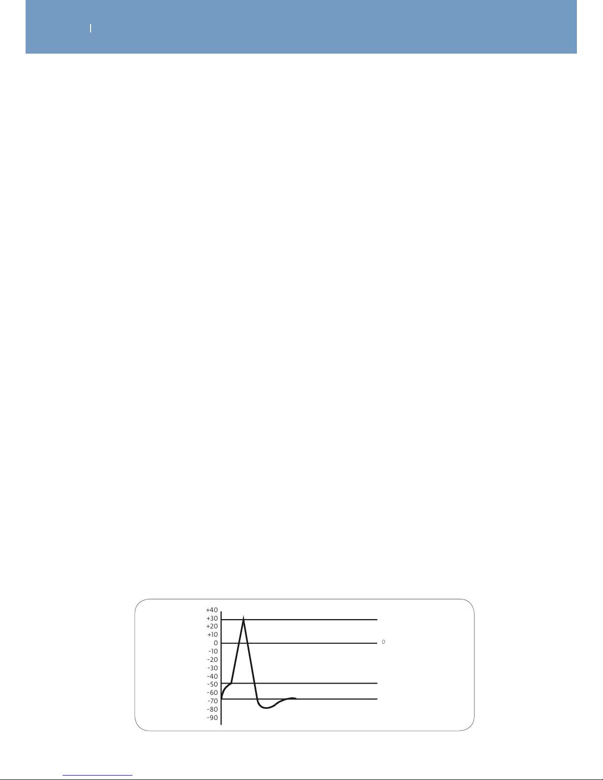
. ELECTROTHERAPY THEORY
EN
WIRELESS PROFESSIONAL
12.1 Introduction
In recent years, significant progress has been made in field of electrotherapy of which many users are
still largely unaware. Changes and improvements in electrotherapy are so numerous that this discipline
appears to be a new concept that can only be applied correctly and eectively using sophisticated, hightech equipment.
The aim of these articles is to develop this new concept for potential users and provide anyone already
working with this equipment with explanations and data that will allow them, based on current
knowledge and scientific work carried out, to optimise the use of their stimulators.
12.1.1 The fundamental law of electrostimulation
Electrostimulation is a technique which involves producing action potentials in the excitable cells (nerve
and muscle) using an electric current.
Nerve cell membranes have a resting potential with an average value of -70mV, as the internal face of the
membrane has negative polarity compared to the external face.
To excite the membrane of the nervous fibre, i.e. causing an action potential to appear at its surface, the
resting potential simply has to be reduced to a certain threshold value, which is -50 mV on average (Fig. 1).
Once this threshold value has been reached the membrane changes from a state of rest to a state of
activity. An action potential appears which then moves along the nerve fibre. The nerve impulse either
goes towards the muscles to instruct them to contract or returns from the surrounding areas towards the
brain to relay information regarding the senses.
Electrostimulating the nerve fibre essentially involves reducing the membrane’s resting potential to the
threshold value by applying an electric current to the skin.
The first question is, of course, which stimulating current to choose.
Which type of current will we use?
A single current must obviously be used, one which can reduce the resting potential to the threshold value
but keep the patient as comfortable as possible. In other words, the electrical parameters of this current
must be kept to a minimum, and its stimulation energy and duration must be as low as possible.
0
+40
+30
+20
+10
0
-10
-20
-30
-40
-50
-60
-70
-80
-90
Action potential
Threshold
Rest potential
Fig. 1
Page 96
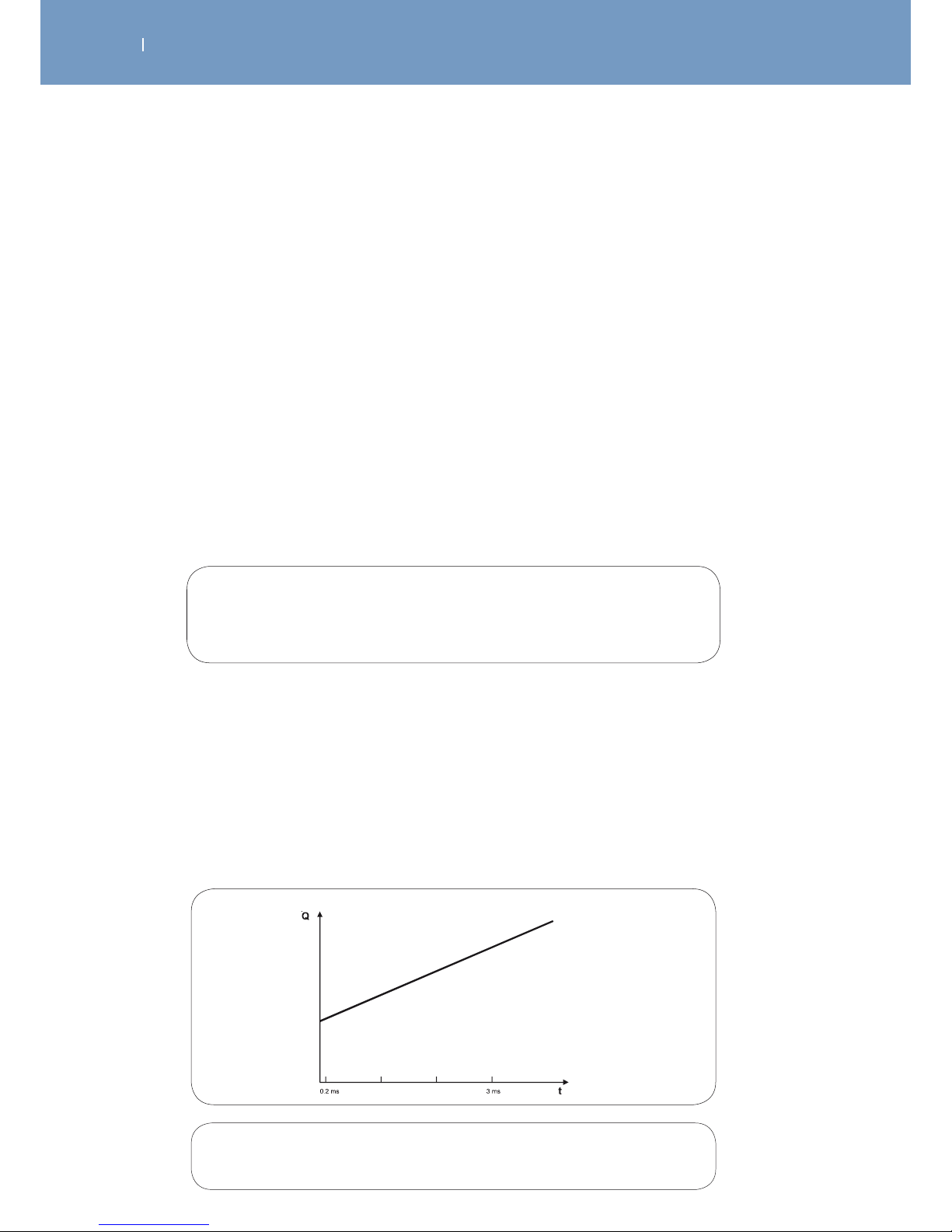
. ELECTROTHERAPY THEORY
EN
WIRELESS PROFESSIONAL
We will therefore need to understand the fundamental law that it must observe in order to find the
optimum qualities of this current.
This first chapter aims to provide a reminder and explanation of this law.
This is followed by a second chapter which, on the basis of this fundamental law and ideas surrounding it,
determines the qualities of the optimum current.
At the turn of the last century, well-known physiologists such as Weiss, Hoorweg, Du Bois Reymond and
Lapicque managed to discover the fundamental law of electrostimulation and its mathematical expression.
Based on Hoorweg’s work, Weiss (a Parisian doctor and physiologist) emphasised the importance of the
quantity of electrical charges created by the stimulation current. His experiments led to the fundamental
observation that to achieve stimulation, it is not the type of current that is significant, but the quantity
of current in a specified period of time. In other words, if the stimulation threshold values are given as a
quantity of electricity (in electrical charges) that must be created to achieve these, the values are similar
even if the electrical pulse with the same overall duration is a dierent shape.
Fig. 2
As a reminder:
the quantity of electrical charges (𝑄) supplied by an electric current with intensity (𝐼)
in a given time (𝑡) is the product of the intensity multiplied by the time.
𝑄𝐼𝑥 𝑡
Since the quantity of electrical charges provided by the stimulation current is the fundamental factor,
Weiss studied the way in which the necessary quantity of charges is modified in order to achieve the
threshold (i.e. to cause stimulation) based on the duration of the current being applied.
He performed a series of measures to determine the relationship between the quantity of current and the
duration of the pulse for durations ranging from 0.23 to 3 ms.
From his experiments, Weiss found that there is a linear relationship between the quantity of charges
required to reach the stimulation threshold and the duration of the pulse (Fig. 2).
Quantity
of current
required to
reach the
stimulation
threshold
Duration of the pulse
Linear relationship between the duration of the electrical pulse and the amount of
electricity applied to reach the stimulation threshold:
𝑄 + 𝑖𝑡
Page 97
. ELECTROTHERAPY THEORY
EN
WIRELESS PROFESSIONAL
Weiss therefore discovered the mathematical relationship that links the pulse duration with the amount of
electricity required to produce the stimulation.
Understandably, he called this relationship the “fundamental formula”:
𝑄
+
𝑖𝑡
𝑄 = the amount of current required to reach the threshold. This is also the quantity of
electrical charges provided by the stimulation current, as the 𝑄 value is given by the
product (𝐼 𝑥𝑡) of the stimulation current intensity multiplied
by its application time.
𝑡 = length of time that the current is applied, which is known as the pulse duration.
𝑖 = a coecient determined by experiment, with the same
quantity as an electric current (intensity).
= a coecient determined by experiment, with the same dimensions as a quantity
of electrical charges; corresponds to the intersection of the straight line with the
y-axis and may be calculated as the 𝑄 value when 𝑡 is equal to zero.
Lapicque, an electrophysiologist who is more widely known than Weiss, did not actually discover a new
law of electrostimulation but he performed a number of experiments which confirmed the fundamental
formula. He defined it dierently to mathematically deduce coecients called the rheobase and chronaxy,
which he gave physiological meaning.
Lapicque developed the “fundamental formula” as follows:
Q q + it
or
Q It
I
: stimulation current intensity
t
: pulse duration
therefore
It q + it
by dividing the two by 𝑡, Lapicque obtained
𝐼 /𝑡 + 𝑖
which is the relationship between the intensity of the current and the time period in
which it must be applied to achieve stimulation (Fig. 3).
Page 98
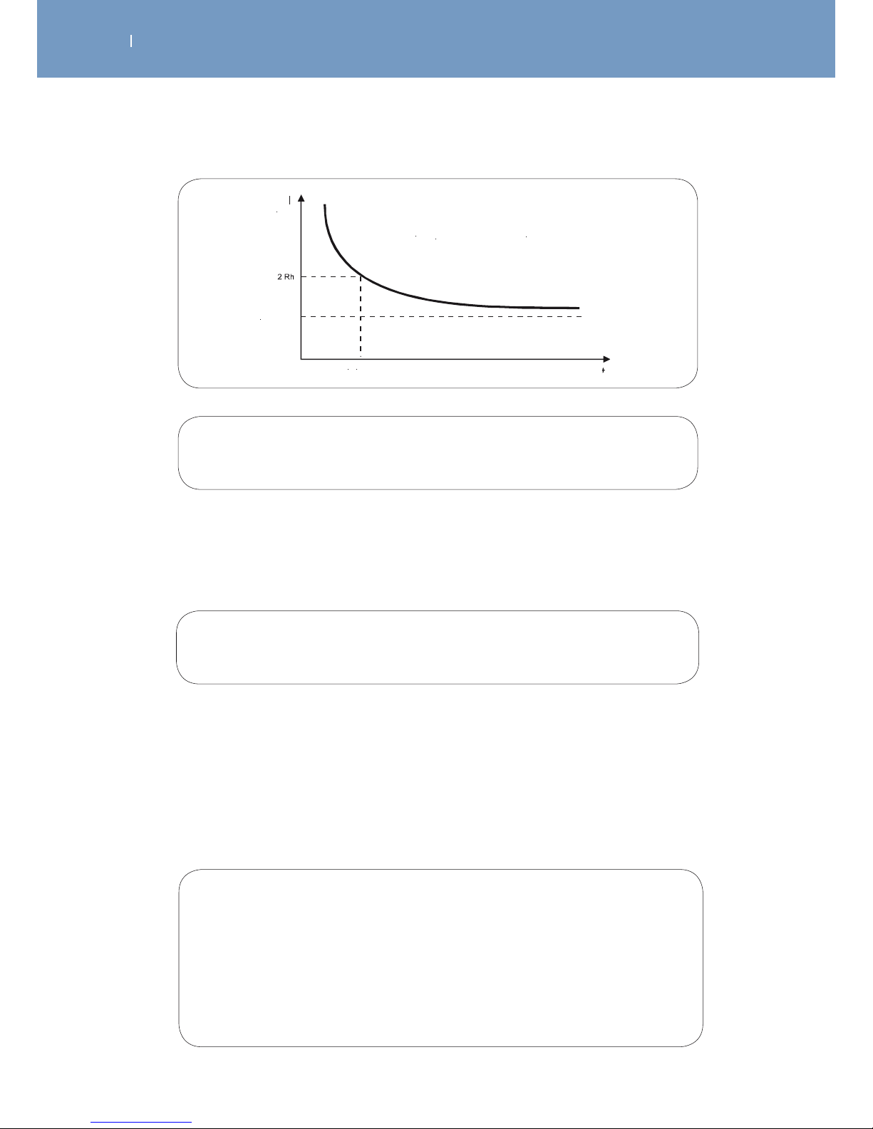
. ELECTROTHERAPY THEORY
EN
WIRELESS PROFESSIONAL
The rheobase, which is the minimum intensity that must be achieved in order to produce stimulation even
if the pulse duration is very long, actually corresponds to the coecient 𝑖 of the Weiss formula which has
dimensions of electrical intensity.
Lapicque gave the name chronaxy to the minimum length of time in which a current with double the
intensity of the rheobase must be applied in order achieve stimulation. In fact, he realised that the
chronaxy is a time constant which characterises the excitability of tissue and that its value is the ratio /𝑖.
Lapicque’s development also shows that, even when the length of time that the current is applied is
infinite, (𝑡 = ∞), the current must have a minimum intensity known as the rheobase (𝑅h) in order to
produce stimulation.
Hyperbolic relationship between the current intensity and pulse duration
demonstrated by Lapicque and given by the formula 𝐼 /𝑡 + 𝑖 , derived from Weiss’
fundamental formula.
if 𝑡 = ∞ therefore /𝑡 = 0
in this case 𝐼 is the rheobase (𝑅ℎ)
and 𝑅ℎ = 𝑖
Intensity-duration curve
Chronaxy
Rheobase
Fig. 3
This means that:
since 𝑅ℎ = 𝑖 when 𝐼 = 2 𝑅ℎ
therefore 𝐼 = 2 𝑖
and 𝑡 is the chronaxy (𝑡 𝑐ℎ)
when 𝐼 = 2 𝑅ℎ
therefore from the equation 𝐼/𝑡+𝑖
the result is 2𝑖 /𝑡𝑐ℎ + 𝑖
therefore 𝑖 /𝑡𝑐ℎ → 𝑡𝑐ℎ = /𝑖
Page 99
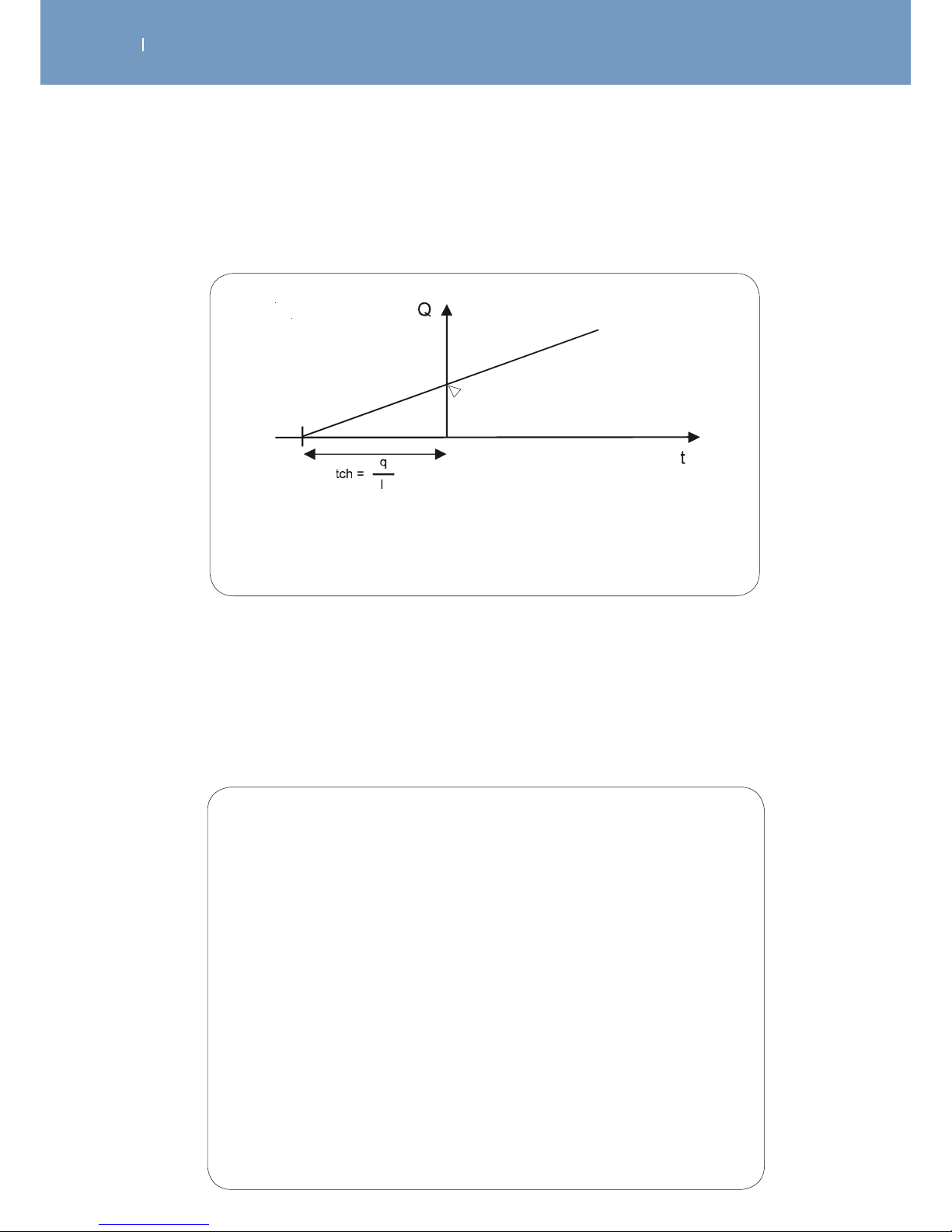
. ELECTROTHERAPY THEORY
EN
WIRELESS PROFESSIONAL
The chronaxy corresponds to the time value when 𝑄 = 0
i.e. 𝑄 + 𝑖𝑡 if 𝑄 = 0 therefore +𝑖𝑡 = 0 therefore 𝑖𝑡 = and 𝑡 /𝑖
Fig. 4
12.1.2 Summary
Electrical stimulation, i.e. reducing resting potential to the stimulation threshold using an electric current, is
a phenomenon that fulfils a fundamental physiological law.
This shows us that:
1 The factor determining stimulation is the quantity of electrical
charges created by the current.
Stimulation must be considered in terms of the amount of current, which is the
product (𝐼𝑥𝑡) of the intensity (𝐼) times the duration of the pulse (𝑡).
2 This amount of current fulfils a fundamental formula:
𝑄 + 𝑖𝑡
where 𝑄 is a linear function of time.
Lapicque expresses this formula in another way by the “intensity - pulse duration”
ratio: 𝐼/𝑡+𝑖and he deduced that
a) the rheobase (𝑅ℎ): minimum intensity that must be reached in order to produce
stimulation using an infinite pulse duration
𝑅ℎ = 𝑖
b) the chronaxy (𝑡𝑐ℎ): minimum time in which a current with double the intensity of
that of the rheobase must be applied in order to produce stimulation
𝑡𝑐ℎ = /𝑖
We can note that the chronaxy can be calculated mathematically from Weiss’ fundamental formula as
shown in Figure 4.
Page 100

. ELECTROTHERAPY THEORY
EN
WIRELESS PROFESSIONAL
12.1.3 References
1. Physiologie Volume II Le Système nerveux et Muscle Charles Kayser, ed. Flammarion
2. Lapicque, L: Définition expérimentale de l’excitabilité Soc. Biologie 77 (1909), 280-283
3. Lapicque, L: La Chronaxie et ses applications physiologiques Hermann & Cie, Paris, 1938
4. Weiss, G: Sur la possibilité de rendre comparable entre eux les appareils servant à l’excitation électrique
5. Arch. itali. Biol. 35 (1901), 413-446
6. Irnich, W: The chronaxy time and its practical importance Pace 3 (1980), 292-301
7. Cours de Physiologie Humaine Volume I Prof. Colin F. Université Libre de Bruxelles
8. Traité de Physiologie Médicale Arthur C. Guyton, ed. Doin
9. Physiologie Humaine Philippe Meyer 2nd edition Flammarion Médecine Science
12.2 The Optimum Current
12.2.2 Characteristics of the optimal current
12.2.1 Introduction
The reminders and ideas developed in the previous chapter, “The fundamental law of electrostimulation”,
must be read before starting this chapter, which describes the qualities of the optimum electrostimulation
current.
The optimum current can be defined as being able to reduce the resting potential to the stimulation
threshold value under Weiss’ law, while also keeping the patient as comfortable as possible. The second
requirement is met by minimising the electrical parameters of the stimulation current, i.e. by using a
minimum amount of electrical intensity (𝐼), pulse duration (𝑡) and electrical energy (𝑊).
Having set out the conditions, we will now determine the qualities of the current that fulfils these
conditions.
12.2.2.1 Electrical stimulation wave produced by the current generator
We can already state that pulses of current, i.e. produced by a current generator, must be used for the
following reasons:
• The first point shown by Weiss is the importance of the quantity of electrical charges provided by the
stimulation current; however, the quantity of charges can only be controlled by a current generator.
• Only a current generator can ensure stable and reproducible conditions, given the variations in skin
resistance.
• If a certain electrical pulse shape is required, only a current generator can maintain a constant current
wave shape as it passes through the skin and tissue.
 Loading...