

Page 1

© 2006 Encore Medical, L.P.
User Manual
Operation & Installation
Instructions for:
Therapy Systems
2791K- Two Channel Combination System
2795K- Four Channel Combination System
2793K- Two Channel Electrotherapy System
2797K- Four Channel Electrotherapy System
Optional Equipment
2780- Therapy System Cart
2767- NiMH Battery Module
27508 and 27079- User Remote Controls
2781- Channel 3/4 Electrotherapy Module
Page 2
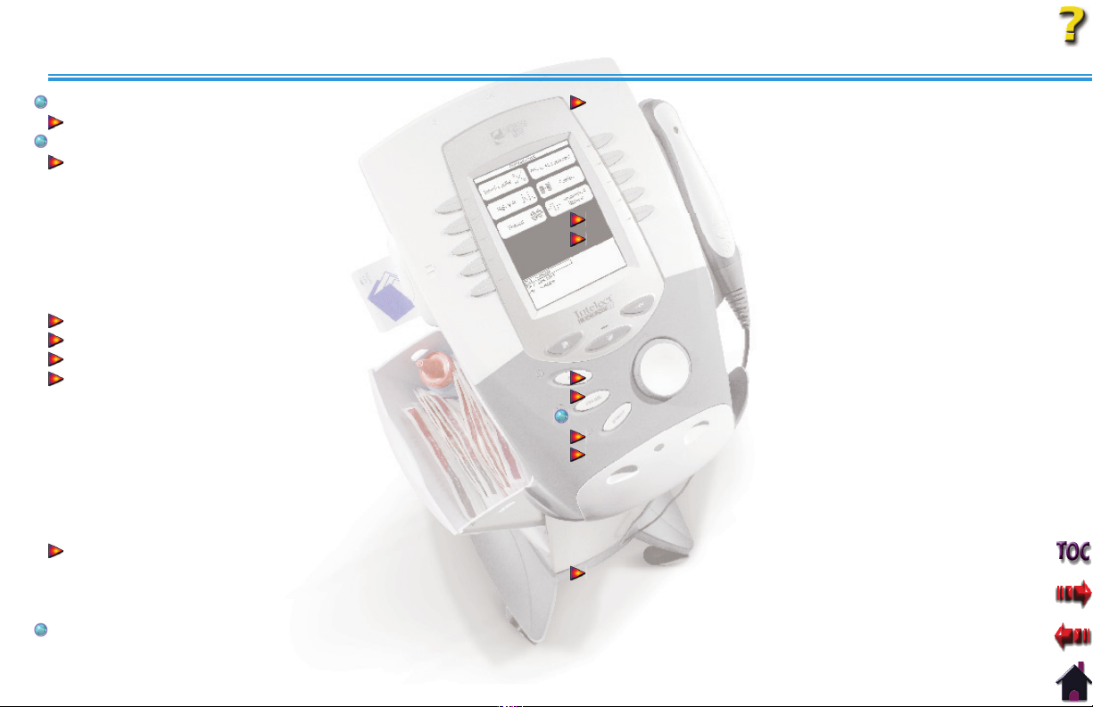
TABLE OF CONTENTS
Intelect® Legend XT Therapy System
FOREWORD . . . . . . . . . . . . . . . . . . . . . . . . . . . . . . . . . . . . . . . . . . . . . . . 1
PRODUCT DESCRIPTION
ABOUT INTELECT LEGEND XT. . . . . . . . . . . . . . . . . . . . . . . . . . . . . . . 2
STANDARD PRECAUTIONARY INSTRUCTIONS
Caution . . . . . . . . . . . . . . . . . . . . . . . . . . . . . . . . . . . . . . . . . . . . . . . . . . . . . . . . . . . 2
Warning. . . . . . . . . . . . . . . . . . . . . . . . . . . . . . . . . . . . . . . . . . . . . . . . . . . . . . . . . . . 2
Danger . . . . . . . . . . . . . . . . . . . . . . . . . . . . . . . . . . . . . . . . . . . . . . . . . . . . . . . . . . . . 2
Dangerous Voltage . . . . . . . . . . . . . . . . . . . . . . . . . . . . . . . . . . . . . . . . . . . . . . . 2
Corrosive. . . . . . . . . . . . . . . . . . . . . . . . . . . . . . . . . . . . . . . . . . . . . . . . . . . . . . . . . . 2
Spontaneous Combustion. . . . . . . . . . . . . . . . . . . . . . . . . . . . . . . . . . . . . . . .2
Biohazardous Materials. . . . . . . . . . . . . . . . . . . . . . . . . . . . . . . . . . . . . . . . . . . 2
CAUTIONS . . . . . . . . . . . . . . . . . . . . . . . . . . . . . . . . . . . . . . . . . . . . . . . . . . . . 3
WARNINGS. . . . . . . . . . . . . . . . . . . . . . . . . . . . . . . . . . . . . . . . . . . . . . . . . . . . 4
DANGERS . . . . . . . . . . . . . . . . . . . . . . . . . . . . . . . . . . . . . . . . . . . . . . . . . . . . . 6
ELECTROTHERAPY INDICATIONS, CONTRAINDICATIONS,
AND ADVERSE EFFECTS
Indications for Russian, TENS, High Voltage Pulsed Current
(HVPC), Interferential and Premodulated waveforms. . . . . . . . . . . . 7
Additional Indications for Microcurrent, Interferential,
Premodulated, and TENS waveforms. . . . . . . . . . . . . . . . . . . . . . . . . . . . . 7
Contraindications. . . . . . . . . . . . . . . . . . . . . . . . . . . . . . . . . . . . . . . . . . . . . . . . . 7
Additional Precautions . . . . . . . . . . . . . . . . . . . . . . . . . . . . . . . . . . . . . . . . . . . 8
Adverse Eff ects . . . . . . . . . . . . . . . . . . . . . . . . . . . . . . . . . . . . . . . . . . . . . . . . . . .8
ULTRASOUND INDICATIONS AND CONTRAINDICATIONS. . . . 9
Indications for Ultrasound. . . . . . . . . . . . . . . . . . . . . . . . . . . . . . . . . . . . . . . . 9
Contraindications. . . . . . . . . . . . . . . . . . . . . . . . . . . . . . . . . . . . . . . . . . . . . . . . . 9
Additional Precautions . . . . . . . . . . . . . . . . . . . . . . . . . . . . . . . . . . . . . . . . . . . 9
NOMENCLATURE . . . . . . . . . . . . . . . . . . . . . . . . . . . . . . . . . . . . . . . . . 10
. . . . . . . . . . . . . . . . . . . . . . . . . . . . . . . . . . . . . . 1
. . . . . . . . . . . . . . . 2
. . . . . . . . . . . . . . . . . . . . . . . . . . . . . . . . . . . . . . 7
INTELECT LEGEND XT ELECTROTHERAPY
AND COMBINATION THERAPY SYSTEMS
Two Channel Electrotherapy System . . . . . . . . . . . . . . . . . . . . . . . . . . . .10
Two Channel Combination System . . . . . . . . . . . . . . . . . . . . . . . . . . . . . .10
Front Access Panel . . . . . . . . . . . . . . . . . . . . . . . . . . . . . . . . . . . . . . . . . . . . . . .11
Rear Access Panel . . . . . . . . . . . . . . . . . . . . . . . . . . . . . . . . . . . . . . . . . . . . . . . .11
USER INTERFACE . . . . . . . . . . . . . . . . . . . . . . . . . . . . . . . . . . . . . . . . . . . . 12
SYMBOL DEFINITIONS. . . . . . . . . . . . . . . . . . . . . . . . . . . . . . . . . . . . . . . 13
System Hardware Symbols . . . . . . . . . . . . . . . . . . . . . . . . . . . . . . . . . . . . . .13
System Software Symbols . . . . . . . . . . . . . . . . . . . . . . . . . . . . . . . . . . . . . . .13
Optional Module and Accessory Symbols. . . . . . . . . . . . . . . . . . . . . . .13
Operator Remote . . . . . . . . . . . . . . . . . . . . . . . . . . . . . . . . . . . . . . . . . . . . . . . .13
Battery Module . . . . . . . . . . . . . . . . . . . . . . . . . . . . . . . . . . . . . . . . . . . . . . . . . . 13
Channel 3/4 Electrotherapy Module . . . . . . . . . . . . . . . . . . . . . . . . . . . .13
GENERAL TERMINOLOGY. . . . . . . . . . . . . . . . . . . . . . . . . . . . . . . . . . . .14
ULTRASOUND . . . . . . . . . . . . . . . . . . . . . . . . . . . . . . . . . . . . . . . . . . . . . . . 14
SPECIFICATIONS. . . . . . . . . . . . . . . . . . . . . . . . . . . . . . . . . . . . . . . . . . 15
SYSTEM SPECIFICATIONS
DIMENSIONS . . . . . . . . . . . . . . . . . . . . . . . . . . . . . . . . . . . . . . . . . . . . . . . .15
Width . . . . . . . . . . . . . . . . . . . . . . . . . . . . . . . . . . . . . . . . . . . . . . . . . . . . . . . . . . . .15
Standard Weight. . . . . . . . . . . . . . . . . . . . . . . . . . . . . . . . . . . . . . . . . . . . . . . . . 15
Power (Combination and Electrotherapy Units). . . . . . . . . . . . . . . . .15
Electrical Type . . . . . . . . . . . . . . . . . . . . . . . . . . . . . . . . . . . . . . . . . . . . . . . . . . .15
Regulatory Compliance. . . . . . . . . . . . . . . . . . . . . . . . . . . . . . . . . . . . . . . . . .15
WAVEFORM SPECIFICATIONS . . . . . . . . . . . . . . . . . . . . . . . . . . . . . . . 16
IFC- Interferential (Traditional 4 Pole) . . . . . . . . . . . . . . . . . . . . . . . . . . .16
Russian. . . . . . . . . . . . . . . . . . . . . . . . . . . . . . . . . . . . . . . . . . . . . . . . . . . . . . . . . . .16
TENS- Symmetrical Biphasic . . . . . . . . . . . . . . . . . . . . . . . . . . . . . . . . . . . . .17
Microcurrent . . . . . . . . . . . . . . . . . . . . . . . . . . . . . . . . . . . . . . . . . . . . . . . . . . . . . 17
. . . . . . . . . . . . . . . . . . . . . . . . . . . . . . . . . . .15
. . . . . . . . . . . . . . . . . . . . 10
i
Page 3
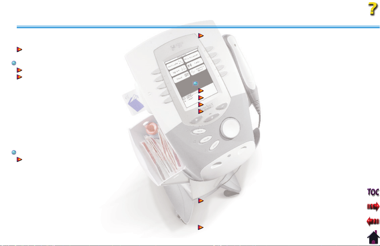
TABLE OF CONTENTS
Intelect® Legend XT Therapy System
Premodulated (Traditional 2 Pole IFC). . . . . . . . . . . . . . . . . . . . . . . . . . .18
High Voltage Pulsed Current (HVPC) . . . . . . . . . . . . . . . . . . . . . . . . . . . .18
ULTRASOUND SPECIFICATIONS . . . . . . . . . . . . . . . . . . . . . . . . . . . . . 19
Ultrasound. . . . . . . . . . . . . . . . . . . . . . . . . . . . . . . . . . . . . . . . . . . . . . . . . . . . . . .19
SETUP. . . . . . . . . . . . . . . . . . . . . . . . . . . . . . . . . . . . . . . . . . . . . . . . . . . . 20
INTELECT LEGEND XT THERAPY SYSTEMS
THERAPY SYSTEM SETUP. . . . . . . . . . . . . . . . . . . . . . . . . . . . . . . . . . . . 21
Clinic Name . . . . . . . . . . . . . . . . . . . . . . . . . . . . . . . . . . . . . . . . . . . . . . . . . . . . . .21
Restoring Default Protocols . . . . . . . . . . . . . . . . . . . . . . . . . . . . . . . . . . . . .22
Restoring Default Unit Settings . . . . . . . . . . . . . . . . . . . . . . . . . . . . . . . . .22
Erasing Patient Data Card . . . . . . . . . . . . . . . . . . . . . . . . . . . . . . . . . . . . . . .23
Setting Date and Time . . . . . . . . . . . . . . . . . . . . . . . . . . . . . . . . . . . . . . . . . . .23
Setting System Volume . . . . . . . . . . . . . . . . . . . . . . . . . . . . . . . . . . . . . . . . . . 24
Displaying Unit Version Information . . . . . . . . . . . . . . . . . . . . . . . . . . . . 24
Pad Contact Quality . . . . . . . . . . . . . . . . . . . . . . . . . . . . . . . . . . . . . . . . . . . . .25
Selecting Language . . . . . . . . . . . . . . . . . . . . . . . . . . . . . . . . . . . . . . . . . . . . .25
Connecting Accessories to the Therapy System. . . . . . . . . . . . . . . . .26
PATIENT PREPARATION . . . . . . . . . . . . . . . . . . . . . . . . . . . . . . . . . . . 27
ELECTROTHERAPY PATIENT PREPARATION
Electrode Placement. . . . . . . . . . . . . . . . . . . . . . . . . . . . . . . . . . . . . . . . . . . . .27
DURA-STICK™ Electrodes . . . . . . . . . . . . . . . . . . . . . . . . . . . . . . . . . . . . . . . .28
Reusable Carbon Electrodes. . . . . . . . . . . . . . . . . . . . . . . . . . . . . . . . . . . . . 28
DURA-STICK™ Electrode Instructions. . . . . . . . . . . . . . . . . . . . . . . . . . . .29
Connecting Lead Wires . . . . . . . . . . . . . . . . . . . . . . . . . . . . . . . . . . . . . . . . . .29
Securing Electrodes . . . . . . . . . . . . . . . . . . . . . . . . . . . . . . . . . . . . . . . . . . . . .29
Reusable Carbon Electrodes. . . . . . . . . . . . . . . . . . . . . . . . . . . . . . . . . . . . . 30
Connecting Lead Wires . . . . . . . . . . . . . . . . . . . . . . . . . . . . . . . . . . . . . . . . . .30
Conductive Medium . . . . . . . . . . . . . . . . . . . . . . . . . . . . . . . . . . . . . . . . . . . . .30
Securing Electrodes . . . . . . . . . . . . . . . . . . . . . . . . . . . . . . . . . . . . . . . . . . . . .30
. . . . . . . . . . . . . . . . . . 20
. . . . . . . . . . . . . . . . . 27
ULTRASOUND PATIENT PREPARATION. . . . . . . . . . . . . . . . . . . . . . 31
Preparing Treatment Area . . . . . . . . . . . . . . . . . . . . . . . . . . . . . . . . . . . . . . .31
Size of Applicator . . . . . . . . . . . . . . . . . . . . . . . . . . . . . . . . . . . . . . . . . . . . . . . .31
Applicator Preparation . . . . . . . . . . . . . . . . . . . . . . . . . . . . . . . . . . . . . . . . . .31
Conductive Medium . . . . . . . . . . . . . . . . . . . . . . . . . . . . . . . . . . . . . . . . . . . . .31
Treatment Area . . . . . . . . . . . . . . . . . . . . . . . . . . . . . . . . . . . . . . . . . . . . . . . . . .31
Applicator LED . . . . . . . . . . . . . . . . . . . . . . . . . . . . . . . . . . . . . . . . . . . . . . . . . . . 31
OPERATION . . . . . . . . . . . . . . . . . . . . . . . . . . . . . . . . . . . . . . . . . . . . . . 32
OPERATOR INTERFACE
HOME SCREEN . . . . . . . . . . . . . . . . . . . . . . . . . . . . . . . . . . . . . . . . . . . . . . . 33
ELECTROTHERAPY SCREEN. . . . . . . . . . . . . . . . . . . . . . . . . . . . . . . . . .34
GENERAL ELECTROTHERAPY WAVEFORM SETUP . . . . . . . . . . .35
Prepare Patient . . . . . . . . . . . . . . . . . . . . . . . . . . . . . . . . . . . . . . . . . . . . . . . . . .35
Select Modality . . . . . . . . . . . . . . . . . . . . . . . . . . . . . . . . . . . . . . . . . . . . . . . . . .35
Select Waveform. . . . . . . . . . . . . . . . . . . . . . . . . . . . . . . . . . . . . . . . . . . . . . . . .35
Edit Waveform Parameters . . . . . . . . . . . . . . . . . . . . . . . . . . . . . . . . . . . . . .35
Installing Patient Interrupt Switch . . . . . . . . . . . . . . . . . . . . . . . . . . . . . .36
Patient Interrupt Switch . . . . . . . . . . . . . . . . . . . . . . . . . . . . . . . . . . . . . . . . .36
Setting Waveform Intensity . . . . . . . . . . . . . . . . . . . . . . . . . . . . . . . . . . . . .36
Intensity Knob Rotation . . . . . . . . . . . . . . . . . . . . . . . . . . . . . . . . . . . . . . . . .36
Start Treatment . . . . . . . . . . . . . . . . . . . . . . . . . . . . . . . . . . . . . . . . . . . . . . . . . .37
Pause Treatment . . . . . . . . . . . . . . . . . . . . . . . . . . . . . . . . . . . . . . . . . . . . . . . . .37
Stop Treatment . . . . . . . . . . . . . . . . . . . . . . . . . . . . . . . . . . . . . . . . . . . . . . . . . .37
Save to Patient Data Card. . . . . . . . . . . . . . . . . . . . . . . . . . . . . . . . . . . . . . . .37
ADJUSTING ELECTROTHERAPY CHANNEL PARAMETERS
DURING TREATMENT
Selecting Channel . . . . . . . . . . . . . . . . . . . . . . . . . . . . . . . . . . . . . . . . . . . . . . .38
Editing Channel Parameters. . . . . . . . . . . . . . . . . . . . . . . . . . . . . . . . . . . . .38
ULTRASOUND . . . . . . . . . . . . . . . . . . . . . . . . . . . . . . . . . . . . . . . . . . . . . . . 39
. . . . . . . . . . . . . . . . . . . . . . . . . . . . . . . . . . . . . .32
. . . . . . . . . . . . . . . . . . . . . . . . . . . . . . . . . . . . . . . . 38
ii
Page 4
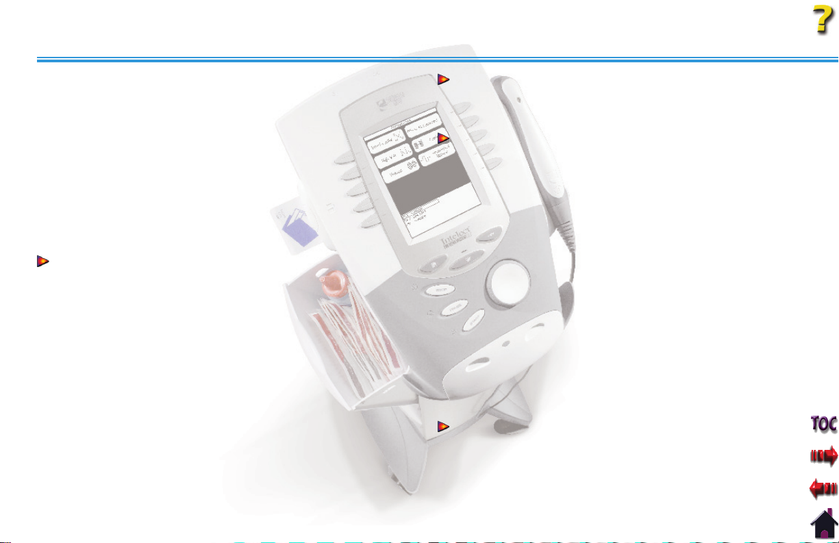
TABLE OF CONTENTS
Intelect® Legend XT Therapy System
Preparing Patient . . . . . . . . . . . . . . . . . . . . . . . . . . . . . . . . . . . . . . . . . . . . . . . .39
Selecting Modality. . . . . . . . . . . . . . . . . . . . . . . . . . . . . . . . . . . . . . . . . . . . . . .39
Editing Ultrasound Parameters. . . . . . . . . . . . . . . . . . . . . . . . . . . . . . . . . .39
Head Warming. . . . . . . . . . . . . . . . . . . . . . . . . . . . . . . . . . . . . . . . . . . . . . . . . . .39
Setting Ultrasound Intensity . . . . . . . . . . . . . . . . . . . . . . . . . . . . . . . . . . . .40
Intensity Knob Rotation . . . . . . . . . . . . . . . . . . . . . . . . . . . . . . . . . . . . . . . . .40
Starting Treatment . . . . . . . . . . . . . . . . . . . . . . . . . . . . . . . . . . . . . . . . . . . . . .40
Pausing Treatment. . . . . . . . . . . . . . . . . . . . . . . . . . . . . . . . . . . . . . . . . . . . . . .40
Stopping Treatment . . . . . . . . . . . . . . . . . . . . . . . . . . . . . . . . . . . . . . . . . . . . .41
Saving to Patient Data Card . . . . . . . . . . . . . . . . . . . . . . . . . . . . . . . . . . . . .41
Editing Ultrasound from Home Screen. . . . . . . . . . . . . . . . . . . . . . . . . .42
Editing Ultrasound from Treatment Review Screen . . . . . . . . . . . . .42
COMBINATION. . . . . . . . . . . . . . . . . . . . . . . . . . . . . . . . . . . . . . . . . . . . . . . 43
Preparing Patient . . . . . . . . . . . . . . . . . . . . . . . . . . . . . . . . . . . . . . . . . . . . . . . .43
Selecting Modality. . . . . . . . . . . . . . . . . . . . . . . . . . . . . . . . . . . . . . . . . . . . . . .43
Accessing Combination Parameters. . . . . . . . . . . . . . . . . . . . . . . . . . . . . 43
Editing Ultrasound Parameters. . . . . . . . . . . . . . . . . . . . . . . . . . . . . . . . . .44
Selecting Waveform . . . . . . . . . . . . . . . . . . . . . . . . . . . . . . . . . . . . . . . . . . . . .44
Using the Patient Interrupt Switch . . . . . . . . . . . . . . . . . . . . . . . . . . . . . .44
Editing Waveform Parameters. . . . . . . . . . . . . . . . . . . . . . . . . . . . . . . . . . .45
Setting Waveform Intensity . . . . . . . . . . . . . . . . . . . . . . . . . . . . . . . . . . . . .45
Intensity Knob Rotation . . . . . . . . . . . . . . . . . . . . . . . . . . . . . . . . . . . . . . . . .45
Setting Ultrasound Intensity . . . . . . . . . . . . . . . . . . . . . . . . . . . . . . . . . . . .45
Intensity Knob Rotation . . . . . . . . . . . . . . . . . . . . . . . . . . . . . . . . . . . . . . . . .45
Starting Treatment . . . . . . . . . . . . . . . . . . . . . . . . . . . . . . . . . . . . . . . . . . . . . .46
Pausing Treatment. . . . . . . . . . . . . . . . . . . . . . . . . . . . . . . . . . . . . . . . . . . . . . .46
Stopping Treatment . . . . . . . . . . . . . . . . . . . . . . . . . . . . . . . . . . . . . . . . . . . . .46
Saving to Patient Data Card . . . . . . . . . . . . . . . . . . . . . . . . . . . . . . . . . . . . .46
ADJUSTING COMBINATION PARAMETERS
DURING TREATMENT
Editing Waveform Parameters. . . . . . . . . . . . . . . . . . . . . . . . . . . . . . . . . . .47
Editing Ultrasound Parameters. . . . . . . . . . . . . . . . . . . . . . . . . . . . . . . . . .47
PATIENT DATA CARD SETTING UP A NEW CARD . . . . . . . . . . . . 48
General Information . . . . . . . . . . . . . . . . . . . . . . . . . . . . . . . . . . . . . . . . . . . . .48
Inserting New Patient Data Card . . . . . . . . . . . . . . . . . . . . . . . . . . . . . . . .48
Setting up Treatment . . . . . . . . . . . . . . . . . . . . . . . . . . . . . . . . . . . . . . . . . . . .48
Setting up a New Patient Data Card . . . . . . . . . . . . . . . . . . . . . . . . . . . .48
Entering Patient ID. . . . . . . . . . . . . . . . . . . . . . . . . . . . . . . . . . . . . . . . . . . . . . .49
Accessing Electrode Placement . . . . . . . . . . . . . . . . . . . . . . . . . . . . . . . . .50
Setting up Electrodes. . . . . . . . . . . . . . . . . . . . . . . . . . . . . . . . . . . . . . . . . . . .50
Electrode Placement. . . . . . . . . . . . . . . . . . . . . . . . . . . . . . . . . . . . . . . . . . . . .50
Accessing Pain Map. . . . . . . . . . . . . . . . . . . . . . . . . . . . . . . . . . . . . . . . . . . . . .51
Selecting Pain Type . . . . . . . . . . . . . . . . . . . . . . . . . . . . . . . . . . . . . . . . . . . . . .51
Adding Pain Locations . . . . . . . . . . . . . . . . . . . . . . . . . . . . . . . . . . . . . . . . . . .51
Selecting Location of Pain . . . . . . . . . . . . . . . . . . . . . . . . . . . . . . . . . . . . . . .52
Editing Pain Locations . . . . . . . . . . . . . . . . . . . . . . . . . . . . . . . . . . . . . . . . . . .52
Deleting Pain Locations . . . . . . . . . . . . . . . . . . . . . . . . . . . . . . . . . . . . . . . . .53
Pain Scales . . . . . . . . . . . . . . . . . . . . . . . . . . . . . . . . . . . . . . . . . . . . . . . . . . . . . . .53
Selecting Pain Scale . . . . . . . . . . . . . . . . . . . . . . . . . . . . . . . . . . . . . . . . . . . . .53
Adjusting Pain Scale . . . . . . . . . . . . . . . . . . . . . . . . . . . . . . . . . . . . . . . . . . . . .53
Saving to Patient Data Card . . . . . . . . . . . . . . . . . . . . . . . . . . . . . . . . . . . . .54
EXISTING PATIENT DATA CARD USE . . . . . . . . . . . . . . . . . . . . . . . . .55
Inserting Existing Patient Data Card. . . . . . . . . . . . . . . . . . . . . . . . . . . . .55
Accessing Patient Data Card. . . . . . . . . . . . . . . . . . . . . . . . . . . . . . . . . . . . .55
Viewing Patient Data Card. . . . . . . . . . . . . . . . . . . . . . . . . . . . . . . . . . . . . . .55
Starting a New Treatment from Patient Data Card . . . . . . . . . . . . . .56
Using the Patient Interrupt Switch . . . . . . . . . . . . . . . . . . . . . . . . . . . . . .56
. . . . . . . . . . . . . . . . . . . . . . . . . . . . . . . . . . . . . . . . 47
iii
Page 5

TABLE OF CONTENTS
Intelect® Legend XT Therapy System
Setting Intensity . . . . . . . . . . . . . . . . . . . . . . . . . . . . . . . . . . . . . . . . . . . . . . . . .56
Intensity Knob Rotation . . . . . . . . . . . . . . . . . . . . . . . . . . . . . . . . . . . . . . . . .56
Starting Treatment . . . . . . . . . . . . . . . . . . . . . . . . . . . . . . . . . . . . . . . . . . . . . .57
Pausing Treatment. . . . . . . . . . . . . . . . . . . . . . . . . . . . . . . . . . . . . . . . . . . . . . .57
Erasing Patient Data Card . . . . . . . . . . . . . . . . . . . . . . . . . . . . . . . . . . . . . . .57
Stopping Treatment . . . . . . . . . . . . . . . . . . . . . . . . . . . . . . . . . . . . . . . . . . . . .57
CREATING USER PROTOCOLS. . . . . . . . . . . . . . . . . . . . . . . . . . . . . . . . 58
General Information . . . . . . . . . . . . . . . . . . . . . . . . . . . . . . . . . . . . . . . . . . . . .58
Selecting Modality. . . . . . . . . . . . . . . . . . . . . . . . . . . . . . . . . . . . . . . . . . . . . . .58
Editing Modality Parameters . . . . . . . . . . . . . . . . . . . . . . . . . . . . . . . . . . . . 58
Selecting Clinical Resources Library. . . . . . . . . . . . . . . . . . . . . . . . . . . . .58
Entering User Protocol Name. . . . . . . . . . . . . . . . . . . . . . . . . . . . . . . . . . . .59
DELETING USER PROTOCOLS. . . . . . . . . . . . . . . . . . . . . . . . . . . . . . . . 60
General Information . . . . . . . . . . . . . . . . . . . . . . . . . . . . . . . . . . . . . . . . . . . . .60
Selecting Clinical Resources Library. . . . . . . . . . . . . . . . . . . . . . . . . . . . .60
Selecting User Protocol to Delete . . . . . . . . . . . . . . . . . . . . . . . . . . . . . . . 60
Deleting User Protocol. . . . . . . . . . . . . . . . . . . . . . . . . . . . . . . . . . . . . . . . . . .60
USING USER PROTOCOLS. . . . . . . . . . . . . . . . . . . . . . . . . . . . . . . . . . . . 61
Accessing User Protocols . . . . . . . . . . . . . . . . . . . . . . . . . . . . . . . . . . . . . . . .61
Selecting User Protocol. . . . . . . . . . . . . . . . . . . . . . . . . . . . . . . . . . . . . . . . . .61
Preparing Patient . . . . . . . . . . . . . . . . . . . . . . . . . . . . . . . . . . . . . . . . . . . . . . . .61
Editing Modality Parameters . . . . . . . . . . . . . . . . . . . . . . . . . . . . . . . . . . . . 61
Using the Patient Interrupt Switch . . . . . . . . . . . . . . . . . . . . . . . . . . . . . .62
Setting Modality Intensity . . . . . . . . . . . . . . . . . . . . . . . . . . . . . . . . . . . . . . .62
Intensity Knob Rotation . . . . . . . . . . . . . . . . . . . . . . . . . . . . . . . . . . . . . . . . .62
Starting Treatment . . . . . . . . . . . . . . . . . . . . . . . . . . . . . . . . . . . . . . . . . . . . . .63
Pausing Treatment. . . . . . . . . . . . . . . . . . . . . . . . . . . . . . . . . . . . . . . . . . . . . . .63
Stopping Treatment . . . . . . . . . . . . . . . . . . . . . . . . . . . . . . . . . . . . . . . . . . . . .63
Saving to Patient Data Card . . . . . . . . . . . . . . . . . . . . . . . . . . . . . . . . . . . . .63
INSTALLATION/REMOVAL . . . . . . . . . . . . . . . . . . . . . . . . . . . . . . . . . 64
INSTALLING THE CHANNEL 3/4 ELECTROTHERAPY
AND NiMH BATTERY MODULE
Nomenclature- Channel 3/4 Electrotherapy Module. . . . . . . . . . . .65
Specifi cations . . . . . . . . . . . . . . . . . . . . . . . . . . . . . . . . . . . . . . . . . . . . . . . . . . . .66
Waveform & Current Specifi cations . . . . . . . . . . . . . . . . . . . . . . . . . . . . .66
Disconnecting Mains Power . . . . . . . . . . . . . . . . . . . . . . . . . . . . . . . . . . . . . 67
Removing Lead Wires and Accessories . . . . . . . . . . . . . . . . . . . . . . . . . .67
Removing Therapy System from Cart . . . . . . . . . . . . . . . . . . . . . . . . . . .67
Releasing Ribbon Cable . . . . . . . . . . . . . . . . . . . . . . . . . . . . . . . . . . . . . . . . .68
Positioning Therapy System and Module . . . . . . . . . . . . . . . . . . . . . . .68
Connecting Ribbon Cable . . . . . . . . . . . . . . . . . . . . . . . . . . . . . . . . . . . . . . . 68
Setting Therapy System onto Module . . . . . . . . . . . . . . . . . . . . . . . . . .69
Securing Therapy System to Module . . . . . . . . . . . . . . . . . . . . . . . . . . .69
Attaching the Lanyard . . . . . . . . . . . . . . . . . . . . . . . . . . . . . . . . . . . . . . . . . .69
Installing Lead Wires and Accessories . . . . . . . . . . . . . . . . . . . . . . . . . . .70
Installing Front Access Panel . . . . . . . . . . . . . . . . . . . . . . . . . . . . . . . . . . . .70
Mounting to Therapy System Cart. . . . . . . . . . . . . . . . . . . . . . . . . . . . . . .70
Connecting Mains Power . . . . . . . . . . . . . . . . . . . . . . . . . . . . . . . . . . . . . . . .70
Turning Therapy System On . . . . . . . . . . . . . . . . . . . . . . . . . . . . . . . . . . . . .71
REMOVING THE CHANNEL 3/4 ELECTROTHERAPY
AND NiMH BATTERY MODULE
Disconnecting Mains Power . . . . . . . . . . . . . . . . . . . . . . . . . . . . . . . . . . . . . 72
Removing Lead Wires and Accessories . . . . . . . . . . . . . . . . . . . . . . . . . .72
Removing Therapy System from Cart . . . . . . . . . . . . . . . . . . . . . . . . . . .72
Removing Screws Securing Module . . . . . . . . . . . . . . . . . . . . . . . . . . . .73
Disconnecting Ribbon Cable at Module. . . . . . . . . . . . . . . . . . . . . . . . . 73
Storing and Securing Ribbon Cable . . . . . . . . . . . . . . . . . . . . . . . . . . . . .73
. . . . . . . . . . . . . . . . . . . . . . . . . . . . . . . 64
. . . . . . . . . . . . . . . . . . . . . . . . . . . . . . . 72
iv
Page 6
TABLE OF CONTENTS
Intelect® Legend XT Therapy System
Attaching the Lanyard . . . . . . . . . . . . . . . . . . . . . . . . . . . . . . . . . . . . . . . . . .74
Installing Lead Wires and Accessories . . . . . . . . . . . . . . . . . . . . . . . . . . .74
Connecting Mains Power . . . . . . . . . . . . . . . . . . . . . . . . . . . . . . . . . . . . . . . .74
Turning Therapy System On . . . . . . . . . . . . . . . . . . . . . . . . . . . . . . . . . . . . .75
GENERAL INFORMATION OPERATOR REMOTE . . . . . . . . . . . . . 76
Installing the Operator Remote . . . . . . . . . . . . . . . . . . . . . . . . . . . . . . . . .76
GENERAL INFORMATION THERAPY SYSTEM CART . . . . . . . . .77
Nomenclature . . . . . . . . . . . . . . . . . . . . . . . . . . . . . . . . . . . . . . . . . . . . . . . . . . .77
Specifi cations . . . . . . . . . . . . . . . . . . . . . . . . . . . . . . . . . . . . . . . . . . . . . . . . . . . .77
MOUNTING THERAPY SYSTEM TO THERAPY SYSTEM CART 78
Assembling the Therapy System Cart . . . . . . . . . . . . . . . . . . . . . . . . . . .78
Preparing the Therapy System Cart . . . . . . . . . . . . . . . . . . . . . . . . . . . . .78
Mounting Therapy System to Cart. . . . . . . . . . . . . . . . . . . . . . . . . . . . . . .78
Connecting Mains Power . . . . . . . . . . . . . . . . . . . . . . . . . . . . . . . . . . . . . . . .79
Installing Storage Bins. . . . . . . . . . . . . . . . . . . . . . . . . . . . . . . . . . . . . . . . . . .79
Removing System from Therapy System Cart . . . . . . . . . . . . . . . . . . .79
OPTION OPERATION. . . . . . . . . . . . . . . . . . . . . . . . . . . . . . . . . . . . . . 80
USING THE OPERATOR REMOTE
Nomenclature . . . . . . . . . . . . . . . . . . . . . . . . . . . . . . . . . . . . . . . . . . . . . . . . . . .80
Operation . . . . . . . . . . . . . . . . . . . . . . . . . . . . . . . . . . . . . . . . . . . . . . . . . . . . . . . . 80
Storing the Operator Remote . . . . . . . . . . . . . . . . . . . . . . . . . . . . . . . . . . .81
USING THE THERAPY SYSTEM CART. . . . . . . . . . . . . . . . . . . . . . . . . 82
Nomenclature . . . . . . . . . . . . . . . . . . . . . . . . . . . . . . . . . . . . . . . . . . . . . . . . . . .82
Operation . . . . . . . . . . . . . . . . . . . . . . . . . . . . . . . . . . . . . . . . . . . . . . . . . . . . . . . . 82
USING THE NiMH BATTERY MODULE. . . . . . . . . . . . . . . . . . . . . . . . 83
Nomenclature . . . . . . . . . . . . . . . . . . . . . . . . . . . . . . . . . . . . . . . . . . . . . . . . . . .83
CHARGING BATTERY MODULE . . . . . . . . . . . . . . . . . . . . . . . . . . . . . . 84
When to Recharge . . . . . . . . . . . . . . . . . . . . . . . . . . . . . . . . . . . . . . . . . . . . . . . 84
. . . . . . . . . . . . . . . . . . . . . . . . . . . . . 80
Charging Temperature. . . . . . . . . . . . . . . . . . . . . . . . . . . . . . . . . . . . . . . . . . .84
BATTERY MODULE SERVICE LIFE . . . . . . . . . . . . . . . . . . . . . . . . . . . . 85
STORING THE BATTERY MODULE. . . . . . . . . . . . . . . . . . . . . . . . . . . .85
Short Term Storage . . . . . . . . . . . . . . . . . . . . . . . . . . . . . . . . . . . . . . . . . . . . . . 85
Long Term Storage. . . . . . . . . . . . . . . . . . . . . . . . . . . . . . . . . . . . . . . . . . . . . . .85
TROUBLESHOOTING . . . . . . . . . . . . . . . . . . . . . . . . . . . . . . . . . . . . . . 86
ERROR CODES
General Information . . . . . . . . . . . . . . . . . . . . . . . . . . . . . . . . . . . . . . . . . . . . .86
REPLACEMENT ACCESSORIES . . . . . . . . . . . . . . . . . . . . . . . . . . . . . 90
GENERAL INFORMATION
MAINTENANCE . . . . . . . . . . . . . . . . . . . . . . . . . . . . . . . . . . . . . . . . . . . 91
CARING FOR THE THERAPY SYSTEM
Cleaning the Therapy System . . . . . . . . . . . . . . . . . . . . . . . . . . . . . . . . . . .91
Cleaning the Lens. . . . . . . . . . . . . . . . . . . . . . . . . . . . . . . . . . . . . . . . . . . . . . . .91
CALIBRATION REQUIREMENTS. . . . . . . . . . . . . . . . . . . . . . . . . . . . . . 91
Calibrating Ultrasound Applicators . . . . . . . . . . . . . . . . . . . . . . . . . . . . .91
FACTORY SERVICE . . . . . . . . . . . . . . . . . . . . . . . . . . . . . . . . . . . . . . . . . . . 91
WARRANTY . . . . . . . . . . . . . . . . . . . . . . . . . . . . . . . . . . . . . . . . . . . . . . 92
. . . . . . . . . . . . . . . . . . . . . . . . . . . . . . . . . . . . . . . . . . . . . . .86
. . . . . . . . . . . . . . . . . . . . . . . . . . . . . . . . . . . . 90
. . . . . . . . . . . . . . . . . . . . . . . .91
v
Page 7

FOREWORD
This manual has been written for the users of the Intelect Legend XT Therapy Systems. It contains general information on the operation,
precautionary practices, and maintenance information. In order to maximize use, efficiency, and the life of the system, please read this
manual thoroughly and become familiar with the controls, as well as the accessories before operating the system.
This manual contains general safety, operating, maintenance, and care instructions as well as installation instructions for the optional
Therapy System Cart, Channel 3/4 Electrotherapy and NiMH Battery for the users of the Intelect Legend XT Therapy two channel
electrotherapy and combination systems.
Specifications put forth in this manual were in effect at the time of publication. However, owing to Chattanooga Group's policy of
continual improvement, changes to these specifications may be made at any time without obligation on the part of Chattanooga Group.
Before administering any treatment to a patient, the users of this equipment should read, understand and follow the information
contained in this manual for each mode of treatment available, as well as the indications, contraindications, warnings and precautions.
Consult other resources for additional information regarding the application of electrotherapy and ultrasound.
PRODUCT DESCRIPTION
The Intelect Legend XT Therapy Systems are two channel electrotherapy and combination systems with the option of adding additional
channels of electrotherapy by installation of the optional Channel 3/4 Electrotherapy Module. Other optional modality modules are
available for separate purchase and may be installed by the end user.
Stay current with the latest clinical developments in the field of electrotherapy and ultrasound. Observe all applicable precautionary
measures for treatment.
Keep informed of appropriate indications and contraindications for the use of electrotherapy and ultrasound.
This equipment is to be used only under the prescription and supervision of a licensed practitioner.
Intelect® Legend XT Therapy System
©2006 Encore Medical Corporation or its affiliates, Austin, Texas, USA. Any use of editorial, pictorial, or layout composition of this publication without express written consent from Chattanooga Group
of Encore Medical, L.P. is strictly prohibited. This publication was written, illustrated, and prepared for distribution by Chattanooga Group of Encore Medical, L.P.
1
Page 8
ABOUT INTELECT LEGEND XT
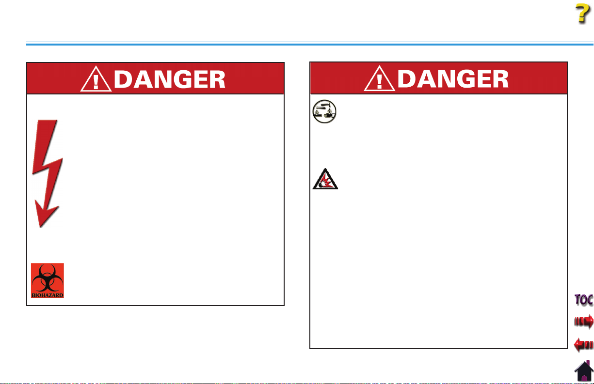
STANDARD PRECAUTIONARY INSTRUCTIONS
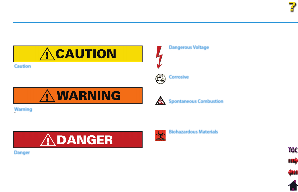
The precautionary instructions found in this section and throughout this manual are indicated by specific symbols. Understand these
symbols and their definitions before operating this equipment. The definition of these symbols are as follows:
Dangerous Voltage
Text with a “Dangerous Voltage” indicator serves to inform
the user of possible hazards resulting in the electrical
Caution
Text with a “CAUTION” indicator will explain possible safety
infractions that could have the potential to cause minor to
moderate injury or damage to equipment.
Warning
Text with a “WARNING” indicator will explain possible safety
infractions that will potentially cause serious injury and
equipment damage.
Danger
Text with a “DANGER” indicator will explain possible safety
infractions that are imminently hazardous situations that would
result in death or serious injury.
charge delivered to the patient in certain treatment
configurations of TENS waveforms.
Corrosive
Text with a “CORROSIVE" indicator will explain possible
safety infractions if the chemical components of the battery
are exposed to air, skin, or other materials.
Spontaneous Combustion
Text with a “SPONTANEOUS COMBUSTION" indicator
will explain possible safety infractions that could create
conditions for a Spontaneous Combustion if the material is
mishandled and not disposed of properly.
Biohazardous Materials
Text with a “BIOHAZARD” indicator serves to inform the
user of possible hazards resulting in improper handling of
components and accessories that have come in contact
with bodily fluids.
NOTE:
Throughout this manual, “NOTE” may be found. These
Notes are helpful information to aid in the particular area
or function being described.
Intelect® Legend XT Therapy System
2
Page 9
ABOUT INTELECT LEGEND XT
CAUTIONS
Read, understand, and practice the precautionary and operating
•
instructions. Know the limitations and hazards associated with
using any electrical stimulation or ultrasound device. Observe the
precautionary and operational decals placed on the unit.
DO NOT operate the Intelect Legend XT Therapy System when
•
connected to any unit other than Chattanooga Group devices.
DO NOT operate this unit in an environment where other devices
•
are being used that intentionally radiate electromagnetic energy in
an unshielded manner.
Ultrasound should be routinely checked before each use to
•
determine that all controls function normally, especially that
the intensity control does properly adjust the intensity of the
ultrasonic power output in a stable manner. Also, determine that
the treatment time control does actually terminate ultrasonic power
output when the timer reaches zero.
DO NOT use sharp objects such as a pencil point or ballpoint pen to
•
operate the buttons on the control panel.
This unit should be operated, transported and stored in
•
temperatures between 59° F and 104° F (15° C and 40° C), with
Relative Humidity ranging from 30%-60%.
Handle Ultrasound Applicator with care. Inappropriate handling of
•
the Ultrasound Applicator may adversely affect its characteristics.
Before each use, inspect Ultrasound Applicator for cracks, which
•
may allow the ingress of conductive fluid.
Intelect® Legend XT Therapy System
Inspect Applicator cables and associated connectors before
•
each use.
The Intelect Legend XT Therapy System is not designed to prevent
•
the ingress of water or liquids. Ingress of water or liquids could cause
malfunction of internal components of the system and therefore
create a risk of injury to the patient.
This equipment generates, uses and can radiate radio frequency
•
energy and, if not installed and used in accordance with the
instructions, may cause harmful interference to other devices in
the vicinity. However, there is no guarantee that interference will
not occur in a particular installation. Harmful interference to other
devices can be determined by turning this equipment on and off.
Try to correct the interference using one or more of the following:
reorient or relocate the receiving device, increase the separation
between the equipment, connect the equipment to an outlet on a
different circuit from that to which the other device(s) are connected
and consult the factory field service technician for help.
The Nylatex® Wraps shipped with this unit contain dry natural rubber
•
and may cause allergic reactions in patients with allergies to latex.
3
Page 10
ABOUT INTELECT LEGEND XT
WARNINGS
U.S.A. Federal Law restricts these devices to sale by, or on the order
•
of, a physician or licensed practitioner. This device should be used
only under the continued supervision of a physician or licensed
practitioner.
•
For continued protection against fire hazard, replace fuses only with
ones of the same type and rating.
•
Make certain the unit is electrically grounded by connecting only to a
grounded electrical service receptacle conforming to the applicable
national and local electrical codes.
•
Care must be taken when operating this equipment around other
equipment. Potential electromagnetic or other interference could
occur to this or to the other equipment. Try to minimize this
interference by not using other equipment in conjunction with it.
•
The safety of TENS waveforms for use during pregnancy or birth has
not been established.
•
TENS is not effective for pain of central origin. (This includes
headache.)
•
TENS should be used only under the continued supervision of a
physician or licensed practitioner.
•
TENS waveforms have no curative value.
•
TENS is a symptomatic treatment, and as such, suppresses the
sensation of pain which would otherwise serve as a protective
mechanism.
•
The user must keep the device out of the reach of children.
•
Electronic monitoring equipment (such as ECG monitors and ECG
alarms) may not operate properly when TENS stimulation is in use.
Intelect® Legend XT Therapy System
Powered muscle stimulators should be used only with the leads and
•
electrodes recommended for use by the manufacturer.
In the event that an Error message or Warning appears beginning
•
with a 2 or 3, immediately stop all use of the system and contact
the dealer or Chattanooga Group for service. Errors and Warnings in
these categories indicate an internal problem with the system that
must be tested by Chattanooga Group or a Field Service Technician
certified by Chattanooga Group before any further operation or use
of the system. Use of a system that indicates an Error or Warning in
these categories may pose a risk of injury to the patient, user or cause
extensive internal damage to the system.
Use of controls or adjustments or performance of procedures other
•
than those specified herein may result in hazardous exposure to
ultrasonic energy.
Before administering any treatment to a patient you should become
•
acquainted with the operating procedures for each mode of
treatment available, as well as the indications, contraindications,
warnings, and precautions. Consult other resources for additional
information regarding the application of Electrotherapy and
Ultrasound.
To prevent electrical shock, disconnect the unit from the power
•
source before attempting any maintenance procedures.
Keep electrodes separated during treatment. Electrodes in contact
•
with each other could result in improper stimulation or skin burns.
Long term effects of chronic electrical stimulation are unknown.
•
4
Page 11
ABOUT INTELECT LEGEND XT
WARNINGS (continued)
Stimulation should not be applied over the anterior neck or mouth.
•
Severe spasm of the laryngeal and pharyngeal muscles may occur
and the contractions may be strong enough to close the airway or
cause difficulty in breathing.
Stimulation should not be applied transthoracically in that the
•
introduction of electrical current into the heart may cause cardiac
arrhythmia.
Stimulation should not be applied over swollen, infected, and
•
inflamed areas or skin eruptions, e.g., phlebitis, thrombophlebitis,
varicose veins, etc.
Stimulation should not be applied over, or in proximity to, cancerous
•
lesions.
Output current density is related to electrode size. Improper
•
application may result in patient injury. If any question arises as to
the proper electrode size, consult a licensed practitioner prior to
therapy session.
The Intelect Legend XT Therapy System optional modules and associated
•
accessories are designed for use only with the Chattanooga Group
Intelect Legend XT Electrotherapy and Combination Therapy Systems.
Intelect® Legend XT Therapy System
5
Page 12
ABOUT INTELECT LEGEND XT
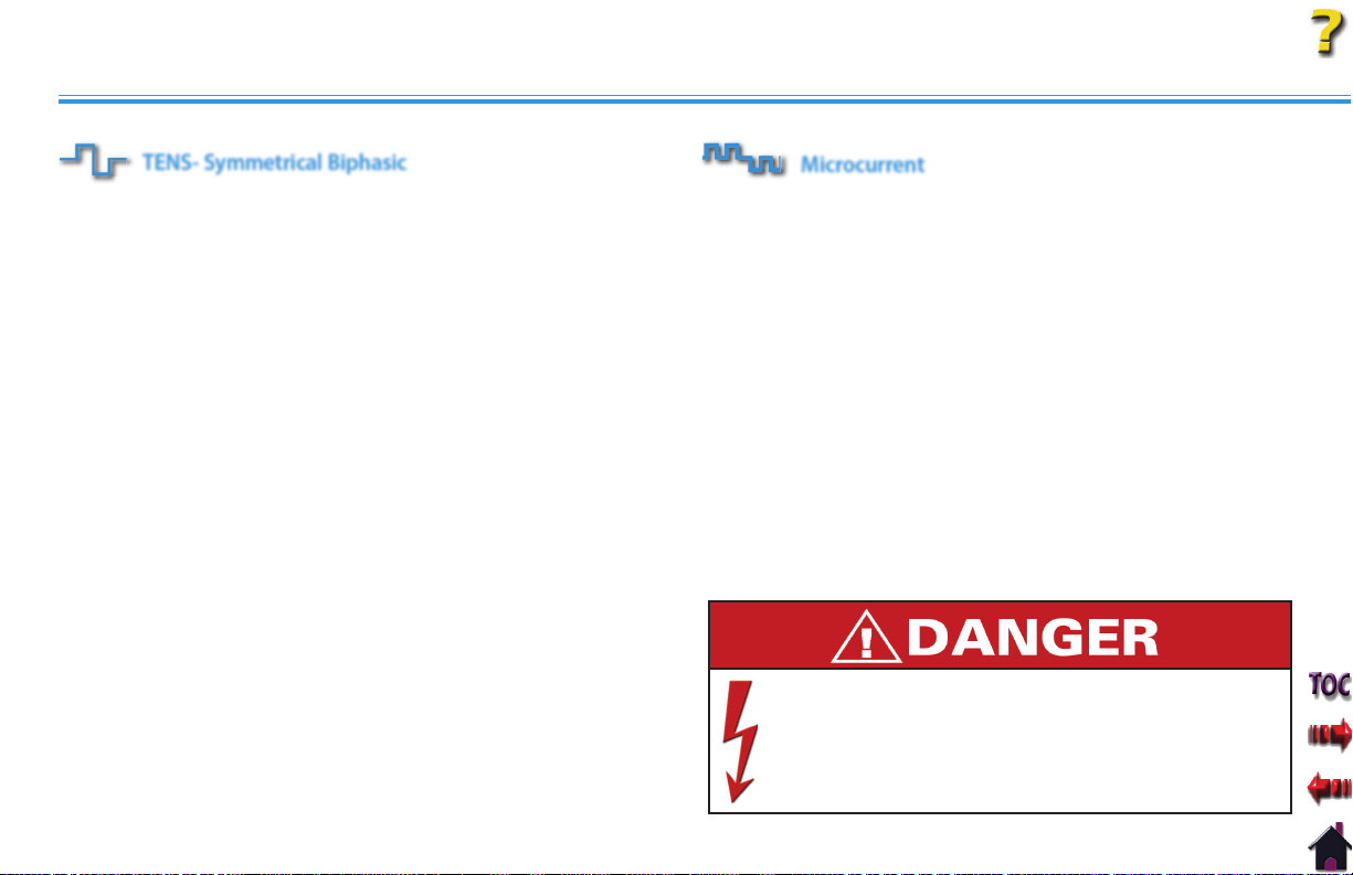
DANGERS
Stimulus delivered by the TENS waveforms of this
•
device, in certain configurations, will deliver a charge of
25 microcoulombs (μC) or greater per pulse and may be
sufficient to cause electrocution. Electrical current of this
magnitude must not flow through the thorax because it
may cause a cardiac arrhythmia.
Patients with an implanted neurostimulation device
•
must not be treated with or be in close proximity to
any shortwave diathermy, microwave diathermy,
therapeutic ultrasound diathermy, or laser diathermy
anywhere on their body. Energy from diathermy
(shortwave, microwave, ultrasound, and laser) can be
transferred through the implanted neurostimulation
system, can cause tissue damage, and can result in
severe injury or death. Injury, damage, or death can
occur during diathermy therapy even if the implanted
neurostimulation system is turned “off.”
Handle, clean, and dispose of components and accessories
•
that have come in contact with bodily fluids according
to National, Local and Facility rules, regulations and
procedures.
Intelect® Legend XT Therapy System
•
NiMH Batteries contain Class E Corrosive materials. In the
event of battery cell rupture or leakage, handle Battery
Module wearing neoprene or natural rubber gloves. Contents
of a ruptured or leaking battery can cause respiratory
irritation. Hypersensitivity to nickel can cause allergic
pulmonary asthma. Contents of cell coming in contact with
skin can cause skin irritation and/or chemical burns.
•
Never, under any circumstances, open the Battery Module
housing or cells. Should an individual cell from a battery
become disassembled, spontaneous combustion of the
negative electrode is possible. There can be a delay between
exposure to air and spontaneous combustion.
•
Charge the Battery Module according to the instructions
found in this manual. Never attempt to charge the Battery
Module on any other charging mechanism.
•
Use the Battery Module only with the Intelect Legend XT
Therapy Systems.
•
Do not reverse the polarity of the Battery Module. Doing so
can increase the individual cell temperature and cause cell
rupture or leakage.
•
Never dispose of Battery Module in fire. Never short circuit
the battery. The battery may explode, ignite, leak or get hot
causing serious personal injury.
Dispose of NiMH batteries according to national, state and
•
local codes and regulations.
6
Page 13

ABOUT INTELECT LEGEND XT
ELECTROTHERAPY INDICATIONS, CONTRAINDICATIONS, AND ADVERSE EFFECTS
Indications for Russian, TENS, High Voltage Pulsed Current
(HVPC), Interferential and Premodulated waveforms
Relaxation of muscle spasms
•
•
Prevention or retardation of disuse atrophy
•
Increase local blood circulation
•
Muscle re-education
•
Maintaining or increasing range of motion
Additional Indications for Microcurrent, Interferential,
Premodulated, and TENS waveforms
•
Symptomatic relief and management of chronic,
intractable pain
•
Post-traumatic acute pain
•
Post-surgical acute pain
Contraindications
This device should not be used for symptomatic local pain relief
•
unless etiology is established or unless a pain syndrome has
been diagnosed.
•
This device should not be used when cancerous lesions are
present in the treatment area.
•
Stimulation should not be applied over swollen,
infected, inflamed areas or skin eruptions (e.g. phlebitis,
thrombophlebitis, varicose veins, etc.).
•
Other contraindications are patients suspected of carrying
serious infectious disease and or disease where it is advisable,
for general medical purposes, to suppress heat or fevers.
•
Electrode placements must be avoided that apply current
to the carotid sinus region (anterior neck) or transcerebrally
(through the head).
•
Safety has not been established for the use of therapeutic
electrical stimulation during pregnancy.
•
Powered muscle stimulators should not be used on patients
with cardiac demand pacemakers.
•
There should not be any use of TENS waveforms on patients
with cardiac demand pacemakers.
Intelect® Legend XT Therapy System
7
Page 14

ABOUT INTELECT LEGEND XT
ELECTROTHERAPY INDICATIONS, CONTRAINDICATIONS, AND ADVERSE EFFECTS (continued)
With TENS waveforms, isolated cases of skin irritation may
Additional Precautions
Caution should be used for patients with suspected or
•
diagnosed heart problems.
•
Caution should be used for patients with suspected or
diagnosed epilepsy.
•
Caution should be used in the presence of the following:
•
When there is a tendency to hemorrhage following acute
trauma or fracture.
•
Following recent surgical procedures when muscle
contraction may disrupt the healing process.
•
Over a menstruating or pregnant uterus.
•
Over areas of the skin which lack normal sensation.
•
Some patients may experience skin irritation or hypersensitivity
due to the electrical stimulation or electrical conductive
medium. The irritation can usually be reduced by using an
alternative conductive medium or an alternative electrode
placement.
•
Electrode placement and stimulation settings should be based
on the guidance of the prescribing practitioner.
•
Powered muscle stimulators should be used only with the
lead wires and electrodes recommended for use by the
manufacturer.
•
occur at the site of electrode placement following long-term
application.
•
The effectiveness of TENS waveforms is highly dependent upon
patient selection by a person qualified in pain management.
Adverse Effects
•
Skin irritation and burns beneath the electrodes have been
reported with the use of powered muscle stimulators.
•
Potential adverse effects with TENS are skin irritation and
electrode burns.
Intelect® Legend XT Therapy System
8
Page 15

ABOUT INTELECT LEGEND XT
ULTRASOUND INDICATIONS AND CONTRAINDICATIONS
Indications for Ultrasound
Application of therapeutic deep heat for the treatment of selected
sub-chronic and chronic medical conditions such as:
Relief of pain, muscle spasms, and joint contractures
•
•
Relief of pain, muscle spasms, and joint contractures that may
be associated with:
•
Adhesive capsulitis
•
Bursitis with slight calcification
•
Myositis
•
Soft tissue injuries
•
Shortened tendons due to past injuries and scar tissues
•
Relief of sub-chronic, chronic pain, and joint contractures
resulting from:
•
Capsular tightness
•
Capsular scarring
Contraindications
•
This device should not be used for symptomatic local pain relief
unless etiology is established or unless a pain syndrome has
been diagnosed.
•
This device should not be used when cancerous lesions are
present in the treatment area.
•
Other contraindications are patients suspected of carrying
serious infectious disease and disease where it is advisable for
general medical purposes to suppress heat or fevers.
Intelect® Legend XT Therapy System
This device should not be used over or near bone growth
•
centers until bone growth is complete.
•
This device should not be used over the thoracic area if the
patient is using a cardiac pacemaker.
•
This device should not be used over a healing fracture.
•
This device should not be used over or applied to the eye.
•
This device should not be used over a pregnant uterus.
•
This device should not be used on ischemic tissues in
individuals with vascular disease where the blood supply would
be unable to follow the increase in metabolic demand and
tissue necrosis might result.
Additional Precautions
Additional precautions should be used when ultrasound is used
on patients with the following conditions:
•
Over an area of the spinal cord following a
Laminectomy, i.e., when major covering tissues have been
removed
•
Over anesthetic areas
•
On patients with hemorrhagic diatheses
9
Page 16
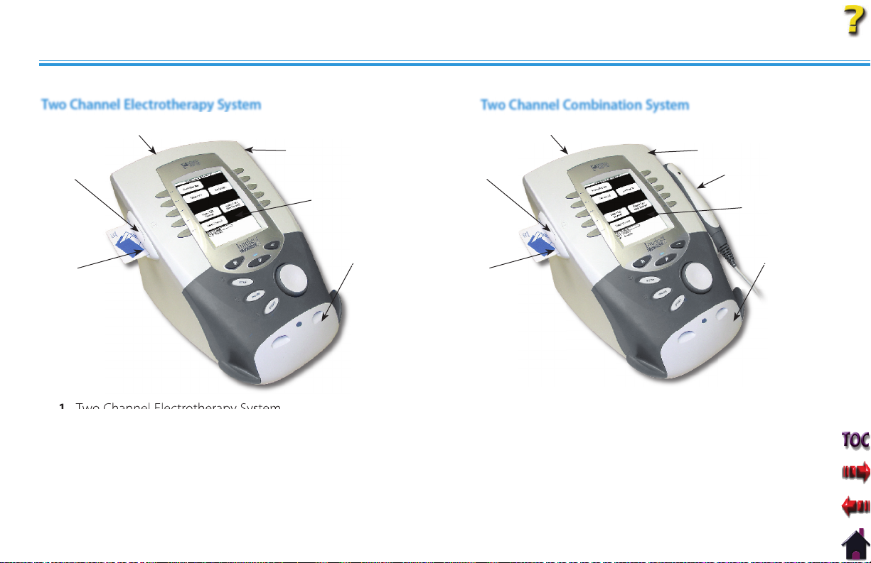
NOMENCLATURE
INTELECT LEGEND XT ELECTROTHERAPY AND COMBINATION THERAPY SYSTEMS
Two Channel Electrotherapy System
Two Channel Combination System
Intelect® Legend XT Therapy System
4
1
6
5
Two Channel Electrotherapy System
1.
User Interface (See Page 12)
2.
Front Access Panel
3.
Rear Access Panel
4.
Patient Data Card access port
5.
Multimedia Card (MMC) access port (Unused)
6.
4
1
6
2
3
10
5
Two Channel Combination System
1.
User Interface (See Page 12)
2.
Front Access Panel
3.
Rear Access Panel
4.
Patient Data Card access port
5.
Multimedia Card (MMC) access port (Unused)
6.
Ultrasound Applicator (5cm2 shown)
7
2
3
Page 17
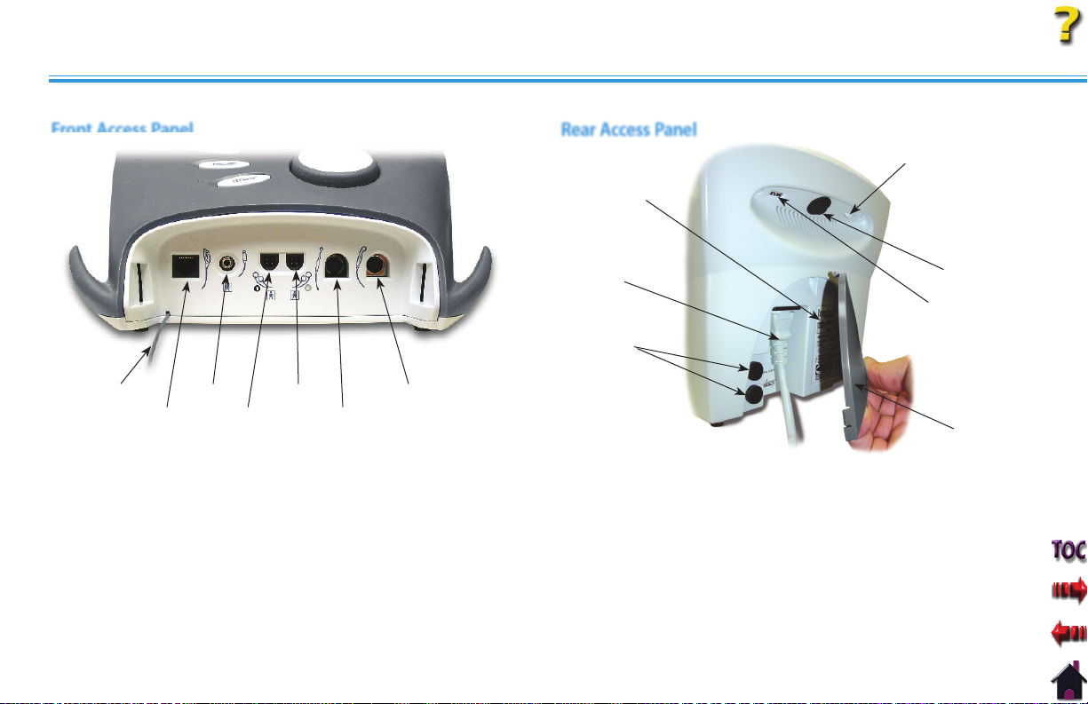
NOMENCLATURE
INTELECT LEGEND XT ELECTROTHERAPY AND COMBINATION THERAPY SYSTEMS (continued)
Front Access Panel Rear Access Panel
7
Intelect® Legend XT Therapy System
1
1
Front Access Panel Lanyard
1.
When reinstalling the Front Access Panel, make certain the
Lanyard does not become kinked.
Operator Remote Control Connector
2.
Patient Interrupt Switch Connector
3.
Channel 1 Lead Wire Connector
4.
Channel 2 Lead Wire Connector
5.
Microcurrent Probe Connector
6.
Ultrasound Applicator Connector
7.
3
2
4
5
6
7
5
4
Screen Contrast Control
1.
Power On/Off Switch
2.
Technical Maintenance Port
3.
Fuses
4.
Mains Power Cord
5.
Rear Access Panel
6.
Serial Decal
7.
11
2
3
6
Page 18
NOMENCLATURE
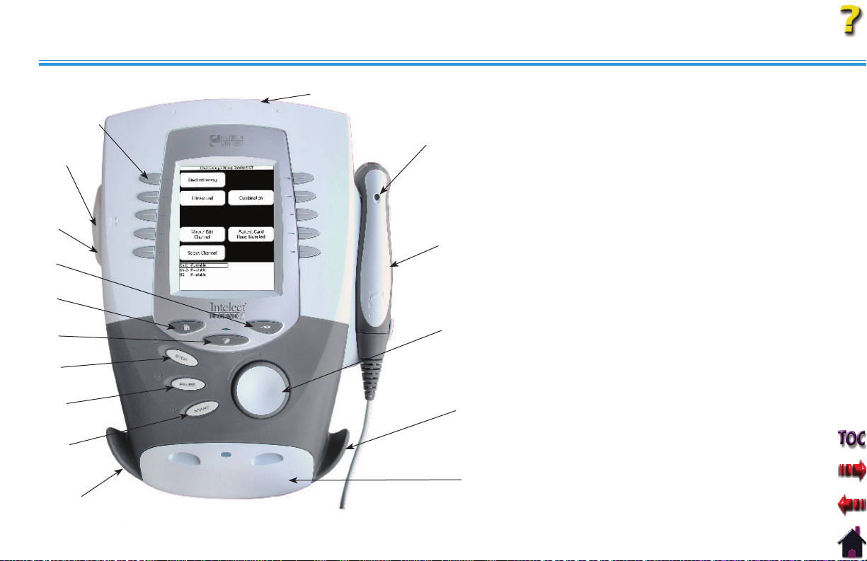
USER INTERFACE
15
14
13
12
11
10
9
8
7
Intelect® Legend XT Therapy System
1
1.
2
3
4
5
Rear Access Panel (See Page 11)
Ultrasound Applicator LED Indicator
2.
(Combination only)
Ultrasound Applicator- 5 cm2 Standard
3.
(Optional 1 cm2, 2 cm2, and 10 cm2
applicators available, Combination only)
Intensity knob
4.
Cable and Lead Wire Hook
5.
Front Access Panel (See Page 11)
6.
Start button
7.
Pause button
8.
Stop button
9.
Clinical Resources Library button
10.
Home Screen button
11.
Back button
12.
Patient Data Card Port
13.
Multimedia Card (MMC) Port (Unused)
14.
User Setup and Parameter Control buttons
15.
6
5
12
Page 19
NOMENCLATURE
Intelect® Legend XT Therapy System
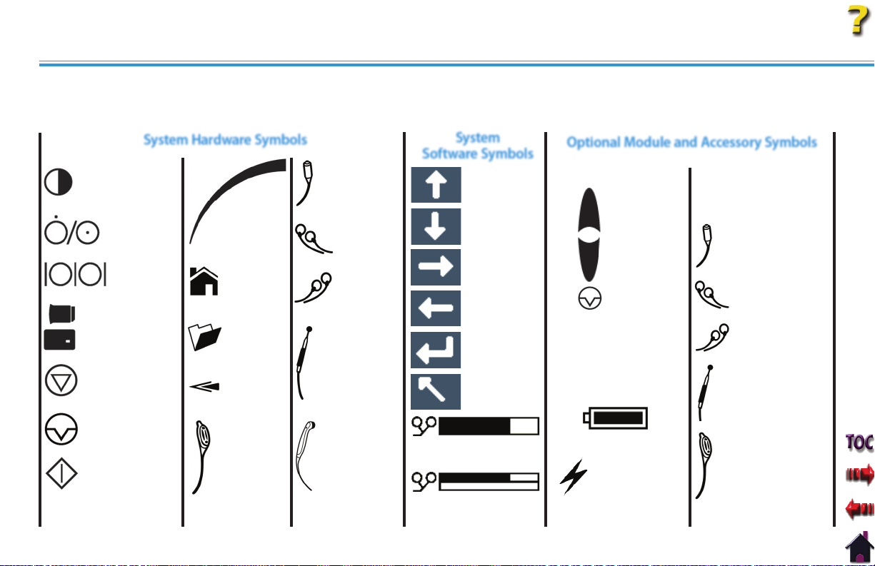
SYMBOL DEFINITIONS
Below are the definitions for all of the symbols used in the Intelect Legend XT hardware and software. Study and learn these symbols
before any operation of the system.
System
Software Symbols
MOVE UP
MOVE DOWN
MOVE RIGHT
MOVE LEFT
ACCEPT AND
RETURN
DO NOT ACCEPT
AND RETURN
Optional Module and Accessory Symbols
Operator Remote
Channel 3/4
Electrotherapy
INCREASE
INTENSITY
DECREASE
INTENSITY
PAUSE
TREATMENT
MANUAL
M
STIMULATION
Battery Module
Module
PATIENT INTERRUPT SWITCH
CHANNEL 3 LEAD WIRES
CHANNEL 4 LEAD WIRES
MICROCURRENT PROBE
CONTRAST CONTROL
ON/OFF SWITCH
DATA PORT
MULTIMEDIA CARD*
PATIENT DATA CARD
STOP TREATMENT
System Hardware Symbols
THERAPY
INTENSITY
CONTROL
HOME
CLINICAL
RESOURCES
LIBRARY
BACK
PATIENT INTERRUPT
SWITCH
CHANNEL 1
LEAD WIRES
CHANNEL 2
LEAD WIRES
MICROCURRENT PROBE
PAUSE TREATMENT
START TREATMENT
* Used for System Software
Upgrades
CHANNEL 1/2
OPERATOR
REMOTE
CONTROL
OPTIONAL
ULTRASOUND
APPLICATOR
PAD CONTACT QUALITY
SINGLE CHANNEL GRAPH
PAD CONTACT QUALITY
DUAL CHANNEL GRAPH
13
CHARGE LEVEL
BATTERY CHARGING
CHANNEL 3/4 OPERATOR
REMOTE CONTROL
OPTIONAL
Page 20

NOMENCLATURE
GENERAL TERMINOLOGY
Below are the definitions for all of the unique terminology used throughout this manual. Study these and become familiar with these
terms for ease of system operation and familiarization with the components and control functionality of the Intelect Legend XT Therapy
System. Some of these terms and definitions refer to a specific button or control on the system. Refer to page 13 for Symbol Definitions.
Back button
The dedicated button on the Main unit, below the display, that
each time pressed takes the user back one screen at a time.
Previous Page button
The button used in some modalities and
functions that will take the user back one page when reading
multiple pages of text.
UP and DOWN Arrows
Controls used in various modality parameter screens to navigate
or change a value up or down within the parameter.
Electrotherapy
Refers to the Electrical muscle or nerve Stimulation modalities of
the system.
System
The primary system with all controls and functions.
Module
Any optional modular modality component designed for
installation onto the System.
ULTRASOUND
1
2
1. Sound Head
That component of the Applicator that makes contact with
the patient during Ultrasound or Combination therapy.
2. Applicator
The assembly that connects to the System and incorporates
the Sound Head.
3. Applicator LED
The component of the Applicator which, when illuminated,
indicates if the Sound Head is emitting Ultrasound.
Intelect® Legend XT Therapy System
3
14
Page 21
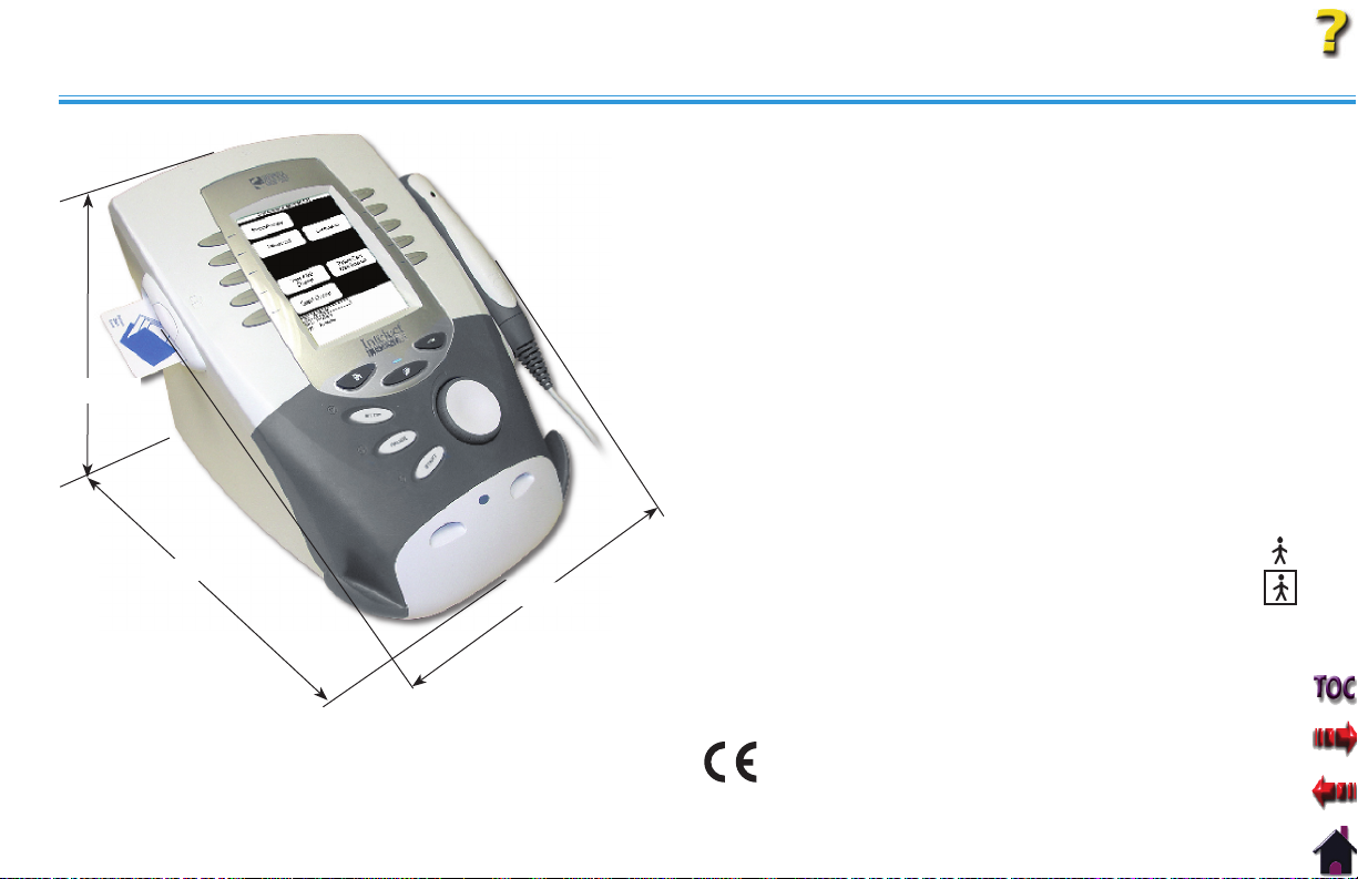
SPECIFICATIONS
Intelect® Legend XT Therapy System
SYSTEM SPECIFICATIONS
HEIGHT
DEPTH
WIDTH
NOTE: All waveforms except High Voltage Pulsed Current (HVPC)
have been designed with a 200 mA current limit.
TENS waveform output intensities are measured, specified
and listed to peak, not peak to peak.
DIMENSIONS
Width
Combination System . . . . . . . . . . . . . . . . . . . . . . . . . 11.375 in (28.9 cm)
Electrotherapy System . . . . . . . . . . . . . . . . . . . . . . . . . 9.750 in (24.8 cm)
Depth (Combination and Electrotherapy System) . 12.750 in (32.4 cm)
Height (Combination and Electrotherapy System) . 8.750 in (22.2 cm)
Standard Weight
Two Channel Combination System. . . . . . . . . . . . . . . . . . 7 lbs (3.2 kg)
Two Channel Electrotherapy System . . . . . . . . . . . . . . . . 6 lbs (2.7 kg)
Power (Combination and Electrotherapy Units)
Input . . . . . . . . . . . . . . . . . . . . . . . . . . . . . . . . . .100 - 240 V - 1.0 A, 50/60 Hz
Output (Internal Power Supply) . . . . . . . . . . . . . . . . . . . . . . . . +24 V, 7.3 A
Fuses . . . . . . . . . . . . . . . . . . . . . . . . . . . . . . . . . . . . . . . . . . Two 6.3 A Time Lag
Electrical Class . . . . . . . . . . . . . . . . . . . . . . . . . . . . . . . . . . . . . . . . . . . . . .CLASS I
Electrical Type
Ultrasound . . . . . . . . . . . . . . . . . . . . . . . . . . . . . . . . . . . . . . . . . . . . . TYPE B
Electrotherapy and sEMG . . . . . . . . . . . . . . . . . . . . . . . . . . . . . .TYPE BF
Regulatory Compliance
UL/IEC/EN 60601-1
IEC/EN 60601-1-2
IEC 60601-2-5
IEC 60601-2-10
0413
15
Page 22

SPECIFICATIONS
WAVEFORM SPECIFICATIONS
Intelect® Legend XT Therapy System
IFC- Interferential (Traditional 4 Pole)
Interferential Current is a medium frequency waveform. Current is
distributed through two channels (four electrodes). The currents
cross each other in the body at the area requiring treatment.
The two currents interfere with each other at this crossing point,
resulting in a modulation of the intensity (the current intensity
increases and decreases at a regular frequency).
Output Mode . . . . . . . . . . . . . . . . . . . . . . . . . . . . . . . . . . . . . . . . . .Electrodes
Carrier Frequency . . . . . . . . . . . . . . . . . . . . . . . . . . . . . . . . . 2,500-5,000 Hz
Beat Frequency . . . . . . . . . . . . . . . . . . . . . . . . . . . . . . . . . . . . . . . . . 1-200 Hz
Sweep Time . . . . . . . . . . . . . . . . . . . . . . . . . . . . . . . . . . . . . . . . . . . . . . . 15 sec
Sweep Low Beat Frequency . . . . . . . . . . . . . . . . . . . . . . . . . . . . 1-200 Hz
Sweep High Beat Frequency . . . . . . . . . . . . . . . . . . . . . . . . . . . . 1-200 Hz
Scan Percentage . . . . . . . . . . . . . . . . . . . . . . . . . . Static, 10%, 40%, 100%
Amplitude . . . . . . . . . . . . . . . . . . . . . . . . . . 0-100 mA Peak into 500 ohm
Treatment Time . . . . . . . . . . . . . . . . . . . . . . . . . . . . . . . . . . . . . 1-60 minutes
Available on Channel . . . . . . . . . . . . . . . . . . . . . . . . . 1 & 2, 3 & 4 Option
*CC= Constant Current
CV= Constant Voltage
Russian
Russian Current is a sinusoidal waveform, delivered in bursts or
series of pulses. This method was claimed by its author (Kots)
to produce maximal muscle strengthening effects without
significant discomfort to the patient.
Output Mode . . . . . . . . . . . . . . . . . . . . . . . . . . . . . . . . . . . . . . . . . .Electrodes
Output Intensity . . . . . . . . . . . . . . . . . . . . . . . . . . . . . . . . . . . . . . . . . . . . . . . 0-100 mA
Channel Mode . . . . . . . . . . . . . . . . . . . . . . . . . Single, Reciprocal, Co-Contract
Duty Cycle . . . . . . . . . . . . . . . . . . . . . . . . . . . . . 10%, 20%, 30%, 40%, 50%
Mode Selection . . . . . . . . . . . . . . . . . . . . . . . . . . . . . . . . . . . . . . . . . . . . . . . CC or CV*
Anti-Fatigue . . . . . . . . . . . . . . . . . . . . . . . . . . . . . . . . . . . . . . . . . . . . . . . . . . . .Off or On
Cycle Time . . . . . .5/5, 4/12, 10/10, 10/20, 10/30, 10/50, Continuous
Burst Frequency (Anti-Fatigue Off ) . . . . . . . . . . . . . . . . . . . . 20-100 bps
Ramp . . . . . . . . . . . . . . . . . . . . . . . . . . . . . . . . . . . . . . . . . . 0.5, 1, 2, and 5 sec
Treatment Time . . . . . . . . . . . . . . . . . . . . . . . . . . . . . . . . . . . . . 1-60 minutes
Available on Channels . . . . . . . . . . . . . . . . . . . . . . . . 1 & 2, 3 & 4 Option
16
Page 23
SPECIFICATIONS
WAVEFORM SPECIFICATIONS (continued)
TENS- Symmetrical Biphasic
The Symmetrical Biphasic waveform has a short pulse duration
and is capable of strong stimulation of nerve fibers in the skin
and in muscle. This waveform is often used in portable muscle
stimulation units, and some TENS devices. Because of its short
pulse duration, the patient typically tolerates the current well,
even at relatively high intensities.
Output Mode . . . . . . . . . . . . . . . . . . . . . . . . . . . . . . . . . . . . . . . . . .Electrodes
Output Intensity . . . . . . . . . . . . . . . . . . . . . . . . . . . . . . . . . . . . . . . . .0-80 mA
Phase Duration . . . . . . . . . . . . . . . . . . . . . . . . . Adjustable 20-1,000 μsec
Frequency . . . . . . . . . . . . . . . . . . . . . . . . . . . . . . . . . . . . . . . . . . . . . . 1-250 Hz
Mode Selection . . . . . . . . . . . . . . . . . . . . . . . . . . . . . . . . . . . . . . . . CC or CV*
Burst Frequency . . . . . . . . . . . . . . . . . . . . . . . . . . . . . . . . . . . . . . . . 0-25 bps
Frequency Modulation . . . . . . . . . . . . . . . . . . . . . . . . . . . . . . . . . 0-250 Hz
Amplitude Modulation . . . . . . . . . . . . Off, 40%, 60%, 80%, and 100%
Treatment Time . . . . . . . . . . . . . . . . . . . . . . . . . . . . . . . . . . . . . 1-60 minutes
*CC= Constant Current
CV= Constant Voltage
Intelect® Legend XT Therapy System
Microcurrent
Microcurrent is a monophasic waveform of very low intensity that
closely simulates the electrical current generated by the human
body. Microcurrent can be applied via electrodes or probe.
Output Mode . . . . . . . . . . . . . . . . . . . . . . . . . . . . . . . . Electrodes or Probe
Output Intensity . . . . . . . . . . . . . . . . . . . . . . . . . . . . . . . . . . . . . . . . . . . . . . .0-1000 μA
Polarity . . . . . . . . . . . . . . . . . . . . . . . . . Positive, Negative, or Alternating
Treatment Time . . . . . . . . . . . . . . . . . . . . . . . . . . . . . . . . . . . . . 1-60 minutes
Available on channels . . . . . . . . . . . . . . . . . . . . . . . . 1 & 2, 3, & 4 Option
Stimulus delivered by the TENS waveforms of this device,
in certain configurations, will deliver a charge of 25
microcoulombs (μC) or greater per pulse and may be
sufficient to cause electrocution. Electrical current of this
magnitude must not flow through the thorax because it may
cause a cardiac arrhythmia.
17
Page 24
SPECIFICATIONS
WAVEFORM SPECIFICATIONS (continued)
Intelect® Legend XT Therapy System
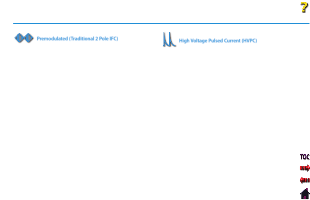
Premodulated (Traditional 2 Pole IFC)
Premodulated Current is a medium frequency waveform. Current
comes out of one channel (two electrodes). The current intensity
is modulated: it increases and decreases at a regular frequency
(the Amplitude Modulation Frequency).
Output Mode . . . . . . . . . . . . . . . . . . . . . . . . . . . . . . . . . . . . . . . . . .Electrodes
Output Intensity . . . . . . . . . . . . . . . . . . . . . . . . . . . . . . . . . . . . . . . . . . . . . . . 0-100 mA
Carrier Frequency . . . . . . . . . . . . . . . . . . . . . . . . . . . . . . . . . . . . . . . .2,500 Hz
Beat Fixed (Sweep Off ) . . . . . . . . . . . . . . . . . . . . . . . . . . . . . . . . . 1-200 Hz
Sweep Low Beat Frequency . . . . . . . . . . . . . . . . . . . . . . . . . . . . 1-200 Hz
Sweep High Beat Frequency . . . . . . . . . . . . . . . . . . . . . . . . . . . 81-200 Hz
Cycle Time . . . . . . . . . . .Continuous, 5/5, 4/12, 10/10, 10/20, 10/30, 10/50
Mode Selection . . . . . . . . . . . . . . . . . . . . . . . . . . . . . . . . . . . . . . . . . . . . . . . CC or CV*
Treatment Time . . . . . . . . . . . . . . . . . . . . . . . . . . . . . . . . . . . . . 1-60 minutes
Available on Channel . . . . . . . . . . . . . . . . . . . . . . . . .1 & 2, 3, & 4 Option
*CC= Constant Current
CV= Constant Voltage
High Voltage Pulsed Current (HVPC)
The High Voltage Pulsed Current (HVPC) has a very brief pulse
duration characterized by two distinct peaks delivered at
high voltage. The waveform is monophasic (current flows in
one direction only). The high voltage causes a decreased skin
resistance making the current comfortable and easy to tolerate.
Output Mode . . . . . . . . . . . . . . . . . . . . . . . . . . . . . . . . Electrodes or Probe
Output Intensity . . . . . . . . . . . . . . . . . . . . . . . . . . . . . . . . . . . . . . . . . . 0-500 V
Polarity . . . . . . . . . . . . . . . . . . . . . . . . . . . . . . . . . . . . . . Positive or Negative
Ramp . . . . . . . . . . . . . . . . . . . . . . . . . . . . . . . . . . . 0.5 sec, 1 sec, 2 sec, 5 sec
Display . . . . . . . . . . . . . . . . . . . . . . . . . . . . . . . . . . . . . Peak Current or Volts
Sweep . . . . . . . . . . . . . .Continuous, 80/120 pps, 1/120 pps, 1/10 pps
Frequency . . . . . . . . . . . . . . . . . . . . . . . . . . . . . . . . . . . . . . . . . . . . 10-120 pps
Cycle Time . . . . . .5/5, 4/12, 10/10, 10/20, 10/30, 10/50, Continuous
Treatment Time . . . . . . . . . . . . . . . . . . . . . . . . . . . . . . . . . . . . . 1-60 minutes
Available on Channels . . . . . . . . . . . . . . . . . . . . . . . .1 & 2, 3, & 4 Option
18
Page 25
SPECIFICATIONS
ULTRASOUND SPECIFICATIONS
Ultrasound
Intelect® Legend XT Therapy System
Frequency . . . . . . . . . . . . . . . . . . . . . . . . . . . . .1 MHz, ± 5%; 3.3 Mhz, ±5%
Duty Cycles . . . . . . . . . . . . . . . . . . . . . . . . . . . 10%, 20%, 50%, Continuous
Pulse Frequency . . . . . . . . . . . . . . . . . . . . . . . . . . . . . . . . . . . . . . . . . . . 100 Hz
Pulse Duration . . . . . . . 1 mSec, ±20%; 2 mSec, ±20%; 5 mSec, ±20%
Output Power
10 cm2 Crystal . . . . . . . . . . . . . . . . 0-20 W at 1 MHz, 0-10 W at 3.3 MHz
5 cm2 Crystal . . . . . . . . . . . . . . . . . . . . . . . . . . . . . . .0-10 W, 1 and 3.3 MHz
2 cm2 Crystal . . . . . . . . . . . . . . . . . . . . . . . . . . . . . . . . 0-4 W, 1 and 3.3 MHz
1 cm2 Crystal . . . . . . . . . . . . . . . . . . . . . . . . . . . . . . . . . 0-2 W 3.3 MHz Only
Amplitude . . . . . . . . . . . . . . . . . . . . 0 to 2.5 w/cm2 in continuous mode,
0-3 w/cm2 in pulsed modes
Output accuracy . . . . . . . . . . . . . . . . . . . ±20% above 10% of maximum
Temporal Peak to Average Ratio: . . . . 2:1, ± 20%, at 50% Duty Cycle
5:1, ± 20%, at 20% Duty Cycle
9:1, ± 20%, at 10% Duty Cycle
Beam Nonuniformity Ratio. . . . . . . . . . . . . . . . . . . . . . . 5.0 : 1 maximum
Beam Type . . . . . . . . . . . . . . . . . . . . . . . . . . . . . . . . . . . . . . . . . . . .Collimating
2
Effective Radiating Areas. . . . . . . . . . . . 10 cm
Crystal: 6.8 cm
5 cm2 Crystal: 3.5 cm2 – 5 cm
2 cm2 Crystal: 1.4 cm2 – 2 cm
1 cm2 Crystal: 0.7 cm2 – 1 cm
Treatment Time . . . . . . . . . . . . . . . . . . . . . . . . . . . . . . . . . . . . . . 1-30 minutes
Head Warming Feature
The Head Warming feature of an Intelect Legend XT Combination
Therapy System utilizes Ultrasound output resulting in warming
of the Sound Head to increase patient comfort.
With Head Warming enabled, ultrasound is emitted without
pressing the Start button. The Applicator LED will not illuminate
during the Head Warming period. US Channel will indicate "Head
Warming".
Output . . . . . . . . . . . . . . . . . . . . . . . 0 - 50% Cycling of maximum power
Frequency . . . . . . . . . . . . . . . . . . . . . . . . . . . . . . . . . . . . . . . . . . . . . . . . 3.3 Mhz
Sound Head Temperature . . . . . . . . . 85 °F - 110 °F (29.4 °C - 43.3 °C)
Do not apply the Ultrasound Applicator to the patient during the
Head Warming period. Applicator must remain in Applicator Hook
during the Head Warming period.
19
2
– 10 cm
2
2
2
2
Page 26

SETUP
INTELECT LEGEND XT THERAPY SYSTEMS
Remove the Intelect Legend XT Two or Four Channel Therapy System and all accessories from the shipping carton. Visually inspect for
damage. Report any damage to the carrier immediately.
Contents of Carton:
•
Intelect Legend XT Two or Four Channel Electrotherapy or Combination System
•
Patient Data Cards (5)
•
Patient Interrupt Switch for Channels 1 and 2
•
Electrotherapy Lead Kit that includes:
•
Nylatex® Wrap- 2 rolls- 2.5 in X 24 in (6 cm X 61 cm)
•
Lead Wires (one for Channel 1 and one for Channel 2)
•
3 in (7.6 cm) Round Carbon Electrodes (one set of 4 - 2 Black and 2 Red)
•
DURA-STICK™ II 2.75 in (7 cm) Round Disposable Electrodes (1 pack of 4)
•
Patient Interrupt Switch for Channels 3 and 4 (Four Channel Systems only)
•
Lead Wires- (one for Channel 3 and one for Channel 4 - Four Channel Systems only)
2
Ultrasound Applicator (Combination Systems Only)
•
5 cm
Cord Set
•
Conductor Transmission Gel - 1 bottle (Combination Systems Only)
•
User Manual
•
Intelect® Legend XT Therapy System
20
Page 27
SETUP
THERAPY SYSTEM SETUP
Accessing Operator Utilities
Plug unit into wall outlet.
Turn system On.
Press the Home and Back buttons
simultaneously.
To return to the System Home
screen, press the Home button.
Clinic Name
Press Clinic Name button.
POWER SWITCH
CLINIC NAME BUTTON
Select the row of alpha or numeric
characters desired by pushing the
button beside the corresponding
row. Select the desired character in
the row by pressing the row button
until the desired letter is framed.
NOTE: To add a space, select the
area to the left of the letter
A.
Once selection is framed, press the
Accept and Return Arrow button.
The character just chosen will
display in the top of the screen and
the cursor will advance to the next
character.
To go back a character press the
Move Left Arrow button. To delete
the character, press the Delete
button.
Once Clinic Name is completed,
press the Save button.
To discard entry, press the Back
button.
Intelect® Legend XT Therapy System
SELECT ROW AND CHARACTER BUTTONS
MOVE
LEFT
DELETE SAVE
BACK
ACCEPT AND
RETURN
21
Page 28
SETUP
THERAPY SYSTEM SETUP (continued)
Restoring Default Protocols
Press Restore Default Protocols
button.
RESTORE DEFAULT
PROTOCOLS BUTTON
Restoring Default Unit Settings
Press the Restore Default Unit
Settings button to restore the
system defaults. This control will
neither change the Date and
Time nor affect any of the Clinical
Protocols stored in the system.
Intelect® Legend XT Therapy System
RESTORE DEFAULT UNIT
SETTINGS BUTTON
Press Yes button to restore the
Protocols to Factory Settings. This
will permanently remove all User
Protocols and Sequences.
NOTE: This will permanently
remove all User Protocols.
If it is not desired to permanently
remove all of the User Protocols
and User Sequences from the
System, press the No button.
PRESS YES BUTTON TO
RESTORE PROTOCOLS
PRESS NO BUTTON TO
KEEP PROTOCOLS
AS THEY ARE
After the settings have been
restored, a message will appear
stating that the Default Unit
Settings are restored. Press any
button to return to Utilities
screen.
22
Page 29
SETUP
THERAPY SYSTEM SETUP (continued)
Erasing Patient Data Card
Install Patient Data Card to be
erased into Patient Data Card
Access Port on the system.
Press Erase Patient Card button.
INSERT
PATIENT
CARD
ERASE PATIENT
CARD BUTTON
Intelect® Legend XT Therapy System
Setting Date and Time
Press Set Date and Time button.
SET DATE
AND TIME
BUTTON
Press the Yes button to erase
all data from Patient Data Card.
Press the No button to keep all
data on Patient Data Card.
After Patient Data Card is
erased, a verification message
will appear. Press any button to
return to the Utilities screen.
YES
BUTTON
NO
BUTTON
Press the UP or Down Arrow
button for the respective area
until desired change is displayed.
After all desired changes are
made, press the Back button to
return to the Utilities screen.
23
PRESS THE RESPECTIVE UP OR DOWN
ARROW BUTTONS TO CHANGE
YES
BUTTON
BACK
BUTTON
Page 30
SETUP
THERAPY SYSTEM SETUP (continued)
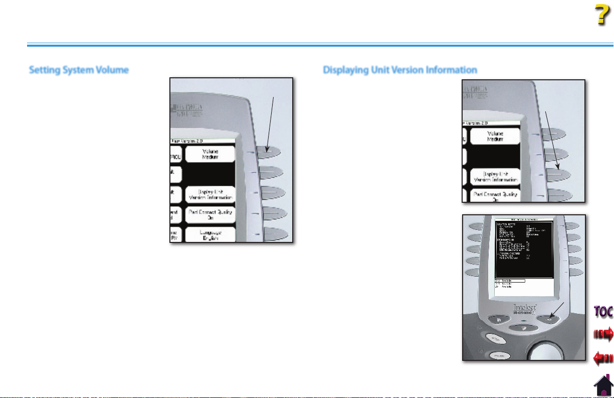
Setting System Volume
Press Volume button until
the desired system volume is
achieved. There are six settings:
Off, X-Low, Low, Med, High and
X-High.
Each time the Volume button is
pressed the setting displayed will
emit three beep tones at that
level.
VOLUME
BUTTON
Displaying Unit Version Information
Press the Display Unit Version
Information button to show
the system software versions
installed.
Press the Back button to return
the Operator Utilities screen.
Intelect® Legend XT Therapy System
PRESS DISPLAY UNIT
VERSION BUTTON TO VIEW
SOFTWARE VERSIONS
BACK
BUTTON
24
Page 31

SETUP
THERAPY SYSTEM SETUP (continued)
Pad Contact Quality
The Pad Contact Quality feature indicates to the user the contact
quality of the electrodes on the patient. This function, if On,
displays a bar graph at the bottom of Treatment Review screen for
the following waveforms only:
The Therapy System Pad Contact Quality default is ON.
Interferential:
•
Dual Channel Graph
IFC Premod (2p):
•
Single Channel Graph
Russian:
•
Single Channel Graph
To turn On or Off, press Pad
Contact Quality button until On
or Off as desired is displayed.
Single Channel Waveforms will
display a single bar graph. Dual
Channel waveforms will display a
double bar graph.
Contact quality is measured by
the amount of the graph filled
with black.
An ideal contact quality is 75% or
more of the graph filled.
SINGLE CHANNEL GRAPH
DUAL CHANNEL GRAPH
PAD CONTACT QUALITY
BUTTON
GOOD CONTACT
QUALITY
CHANNEL 1:
GOOD CONTACT QUALITY
CHANNEL 2:
NO CONTACT QUALITY
Selecting Language
To change the language
displayed on the system, press
the Language button until the
desired language is displayed.
Press Home button to set the
language and return to Home
screen.
If Unit Default Settings are
restored, the language will revert
back to English.
Intelect® Legend XT Therapy System
LANGUAGE
BUTTON
PRESS HOME BUTTON
TO SET LANGUAGE
25
Page 32

SETUP
THERAPY SYSTEM SETUP (continued)
Connecting Accessories to the Therapy System
Install Lead Wires, Ultrasound Applicator, Patient Interrupt Switch,
and any other accessories according to the Front Access Panel as
illustrated below.
Refer to page 13 for Symbol Definitions.
Intelect® Legend XT Therapy System
OPERATOR REMOTE
OPTIONAL
CHANNEL 1/2
PATIENT INTERRUPT SWITCH
CHANNEL 1
LEAD WIRE
BLACK
CHANNEL 2
LEAD WIRE
GREY
MICROCURRENT PROBE
OPTIONAL
ULTRASOUND APPLICATOR
COMBO SYSTEMS ONLY
26
Page 33

PATIENT PREPARATION
ELECTROTHERAPY PATIENT PREPARATION
Electrode Placement
•
Examine the skin for any wounds and clean the skin.
•
Apply the electrodes to the treatment area.
•
Ensure the electrodes are applied securely to the skin.
•
Ensure good contact between each electrode and the skin.
•
Check the electrode contact regularly during the treatment.
•
Examine the skin again after the treatment.
•
Choose electrodes that fit the anatomy.
•
Refer to the respective electrode type instructions on
through 30.
Follow electrode manufacturer instructions.
•
pages 28
Intelect® Legend XT Therapy System
Keep electrodes separated during treatment. Electrodes in contact
•
with each other could result in improper stimulation or skin burns.
Output current density is related to electrode size. Improper
•
application may result in patient injury. If any question arises as to
the proper electrode size, consult a licensed practitioner prior to
therapy session.
Powered muscle stimulators should be used only with the leads and
•
electrodes recommended for use by the manufacturer.
27
Page 34

PATIENT PREPARATION
ELECTROTHERAPY PATIENT PREPARATION (continued)
DURA-STICK™ Electrodes
Chattanooga Group DURA-STICK™ Electrodes are a self adhesive,
single patient, one time use disposable product designed
specifically for use with Chattanooga Group Electrotherapy
systems.
It is recommended that Chattanooga Group DURA-STICK™
Electrodes be used whenever possible to ensure the highest level
of contact with the treatment area and most uniform delivery of
the prescribed electrotherapy treatment.
Properly dispose of used DURA-STICK™ Electrodes upon
completion of the therapy session.
Intelect® Legend XT Therapy System
Reusable Carbon Electrodes
If used for delivery of electrotherapy, the Carbon Electrodes
must be used with a conductive medium such as Conductor™
Transmission Gel.
These Carbon Electrodes should be secured to the treatment area
using the Nylatex® Wraps shipped with the Therapy System.
28
Page 35

PATIENT PREPARATION
ELECTROTHERAPY PATIENT PREPARATION (continued)
Dura-Stick™ Electrode Instructions
Connecting Lead Wires
Insert the lead with the Red (+) electrode
connector into one DURA-STICK™ Electrode.
Insert the lead with the Black (-) electrode
connector into the other electrode.
Make certain the lead wires are
seated completely into the electrodes.
NOTE: Use of conductive medium or
sponges is not required or
recommended. DURA-STICK™
Electrodes are manufactured to
ensure the optimum conductivity
during therapy when properly
applied.
LEAD WIRE SEATED
RED +
LEAD WIRE
Securing Electrodes
Remove the DURA-STICK™ Electrodes from
the protective backing and apply to the
treatment area as prescribed. Ensure the
entire electrode surface is in contact with
patient skin by pressing into place.
Intelect® Legend XT Therapy System
BLACK
LEAD WIRE
29
Page 36

PATIENT PREPARATION
ELECTROTHERAPY PATIENT PREPARATION (continued)
Reusable Carbon Electrodes
Connecting Lead Wires
Insert the lead with the Red (+) electrode
connector into Red electrode. Insert the
lead with the black (-) electrode connector
into the Black electrode.
Make certain the lead wires are seated
completely into the electrodes.
LEAD WIRE
SEATED
RED +
LEAD WIRE
BLACK
LEAD WIRE
Conductive Medium
Liberally apply Conductor™ Transmission
Gel to electrode prior to placement on
patient.
Intelect® Legend XT Therapy System
Securing Electrodes
®
Use the Nylatex
Wrap to secure each
electrode in position on the patient.
SECURE WITH
NYLATEX
The Nylatex® Wraps contain dry natural rubber and
may cause allergic reactions in patients with allergies
to latex.
30
Page 37

PATIENT PREPARATION
ULTRASOUND PATIENT PREPARATION
Preparing Treatment Area
Examine the skin for any wounds and clean the skin. Liberally apply Conductor™
Size of Applicator
Sound Heads are available in the sizes shown below.
2
1 CM
5 CM
STANDARD
2
2 CM
2
10 CM
2
Applicator Preparation
Clean applicator before each therapy session with warm soapy
water.
Conductive Medium
Transmission Gel or equivalent to
the treatment area on the patient.
Treatment Area
Move the Sound Head during
therapy session in a circular
motion. The area treated should
be two times the diameter of the
Sound Head.
Applicator LED
After pressing the Start button
to begin Ultrasound Therapy, the
Applicator LED will illuminate
green indicating that the
Applicator is emitting Ultrasound.
Intelect® Legend XT Therapy System
APPLY
CONDUCTIVE GEL
APPLICATOR
LED
31
Page 38

OPERATION
Intelect® Legend XT Therapy System
OPERATOR INTERFACE
The Intelect Legend XT Therapy System Operator Interface houses all of the functions and controls necessary for the operator to access all
operator utilities, modalities, and parameters for modification and system setup.
Clinical Resources Library button
Top of Screen
1
2
12
11
10
9
12
8
1.
The Title Bar indicates the Screen Title for
the modality being used. When at the
System Home screen, the Clinic Name is
displayed.
Center of Screen
2.
3
4
5
6
7
Contains available Modality options.
Select Modality by pressing the desired
Modality button and then make
parameter modifications.
Bottom of Screen
3.
Displays available channels and their
respective status. Displays Treatment
Time and status. After starting therapy
session, Modality and Parameter buttons
are used to select and modify channel
parameters.
Unit On Indicator
4.
Illuminates green when System is
connected to an AC mains power source.
When the System is On, the indicator
will illuminate blue. With System On,
and if the system sits unused, the Screen
Saver initiates (blank screen) and the Blue
Indicator will flash.
Back button
5.
Used to return back one screen. Used in
conjunction with the Home button to
access the Operator Utilities screen.
6.
Used to access User Protocols screen.
Intensity knob
7.
Rotate clockwise to increase Modality
intensity. Rotate counterclockwise to
decrease Modality intensity.
Start button
8.
Press to start therapy session after all
initial parameters have been set.
Pause button
9.
Press to pause a therapy session. Press
again to restart session.
Stop button
10.
Press to completely stop the therapy
session.
Home button
11.
Used to go back to the System Home
screen. Used in conjunction with the
Back button to access the Operator
Utilities screen.
Modality and Parameter buttons
12.
Used to select modality and edit
treatment parameters.
32
Page 39

OPERATION
Intelect® Legend XT Therapy System
HOME SCREEN
The Intelect Legend XT Home screen affords access to all of the system modalities and functions. The area surrounding the screen has 10
modality and parameter modification buttons.
Electrotherapy
1.
Accesses all the available waveforms and parameter editing controls.
Ultrasound
2.
1
2
3
Accesses the Ultrasound setup screen and parameter editing controls.
Combination
3.
Accesses combination therapy setup screens and parameter editing controls.
View/Edit Channel
4.
Accesses the selected channel and allows editing of the channel's parameters
4
6
5
during therapy. Also used in the saving of information to the Patient Data Card.
Patient Card
5.
Accesses Patient Data Card data.
Select Channel
6.
Use to select desired channel for viewing and editing of channel parameters.
33
Page 40

OPERATION
ELECTROTHERAPY SCREEN
Intelect® Legend XT Therapy System
The screen allows the operator to access, set up, and modify
parameters of each of the available waveforms within the
Intelect Legend XT Therapy System. The following pages give a
general explanation of a treatment setup.
Refer to the Specifications section, beginning on
for detailed specifications of the system and each available
waveform.
NOTE: Give patient the appropriate Patient Inter rupt Switch
for the channels being used. Prior to starting a therapy
session, explain to the patient how to use the Patient
Interrupt Switch.
page 15,
34
Page 41

OPERATION
Intelect® Legend XT Therapy System
GENERAL ELECTROTHERAPY WAVEFORM SETUP
The following information is an example of step by step setup for the Electrotherapy waveforms. All waveforms in the Intelect Legend XT
Therapy System are set up and edited in the same basic fashion. The following setup instructions use Interferential Waveform.
Prepare Patient
Refer to
pages 27 through 30 for electrode
selection, preparing patient, and securing
electrodes.
Select Modality
Select Waveform
Press button beside the desired waveform
from the listing on the screen.
PRESS DESIRED WAVEFORM BUTTON
Edit Waveform Parameters
Press Edit button to access waveform
parameters.
Press the corresponding button to edit
each parameter as prescribed.
Press the Electrotherapy button on the
Home screen.
ELECTROTHERAPY
BUTTON
EDIT BUTTON
PARAMETER
BUTTONS
BACK
BUTTON
Refer to Specifications section of this
manual for all available waveforms on the
Intelect Legend XT Therapy System.
35
Press the Back button to return to the
Treatment Review screen.
Page 42
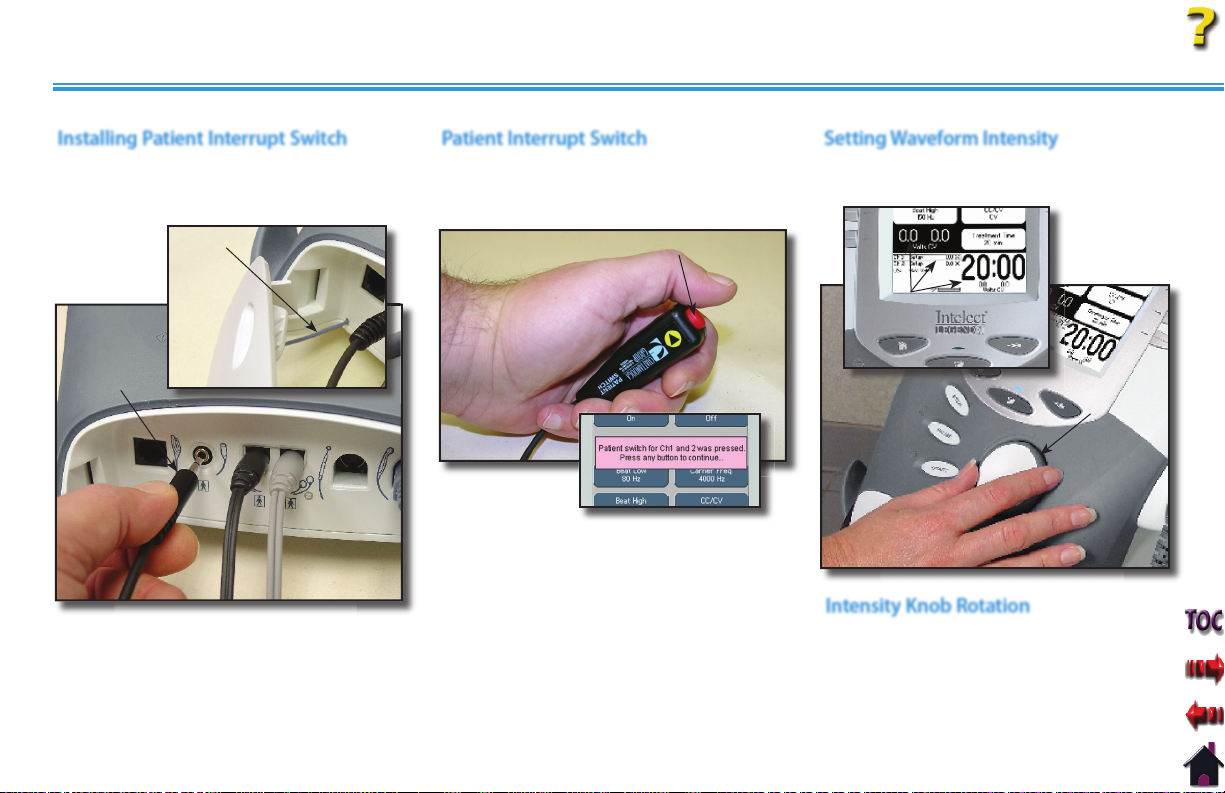
OPERATION
GENERAL ELECTROTHERAPY WAVEFORM SETUP (continued)
Installing Patient Interrupt Switch
Make certain the Patient Interrupt Switch is
connected to the Therapy System. Refer to
page 13 for Symbol Definitions.
LANYARD
PATIENT
INTERRUPT
SWITCH
NOTE: When reinstalling the Front Access
Panel, make certain the Lanyard does
not become kinked.
Patient Interrupt Switch
Give Patient Interrupt Switch to patient
and explain that pressing the Red button
once pauses the therapy session.
PRESSING BUTTON ONCE PAUSES SESSION
If Patient Interrupt Switch is depressed, the
treatment will be paused and a message
will appear on the System screen.
Press any button to clear the message.
NOTE: If the Patient Interrupt Switch is
depressed a second time, the
message will clear from the
screen and the treatment will
remain paused.
Intelect® Legend XT Therapy System
Setting Waveform Intensity
Set intensity by rotating the Intensity Control
Knob to the prescribed level.
INTENSITY
DISPLAYED
ROTATE
INTENSITY
KNOB
Intensity Knob Rotation
Clockwise- Increases Intensity
Counterclockwise- Decreases Intensity
36
Page 43

OPERATION
GENERAL ELECTROTHERAPY WAVEFORM SETUP (continued)
Intelect® Legend XT Therapy System
Start Treatment
Press the Start button to begin therapy
session.
START
BUTTON
Pause Treatment
Press the Pause button to pause therapy
session and maintain remaining time. To
resume treatment, press the Pause button
again.
PAUSE
BUTTON
Stop Treatment
To Stop treatment, press the Stop button
once. Treatment will stop and the
Completed Treatment Review screen will
display.
STOP BUTTON
Save to Patient Data Card
After session is complete, press the Save
to Patient Card button. Refer to pages 48
through 57 for Patient Data Card Setup
and use.
37
Page 44

OPERATION
Intelect® Legend XT Therapy System
ADJUSTING ELECTROTHERAPY CHANNEL PARAMETERS DURING TREATMENT
The Electrotherapy channel parameters may be changed during a treatment session without pausing or stopping the treatment. The
waveform Intensity may be increased or decreased at any time during the session without utilizing this process.
Selecting Channel
Press the Home button.
Press the Select Channel button until the
channel desired is framed.
VIEW/EDIT
BUTTON
SELECT CHANNEL
BUTTON
DESIRED
CHANNEL
FRAMED
Editing Channel Parameters
Press the Edit button. Edit parameters as
desired.
EDIT
BUTTON
PARAMETER
BUTTONS
When finished editing the selected
channel, press the Home button to select
another channel if desired.
Press the View/Edit Channel button. The
Treatment Review screen will display.
To view the Treatment Review screen, if
the Home screen is displayed, press the
View/Edit Channel button. If the Edit
screen is displayed, press the Back button.
38
Page 45
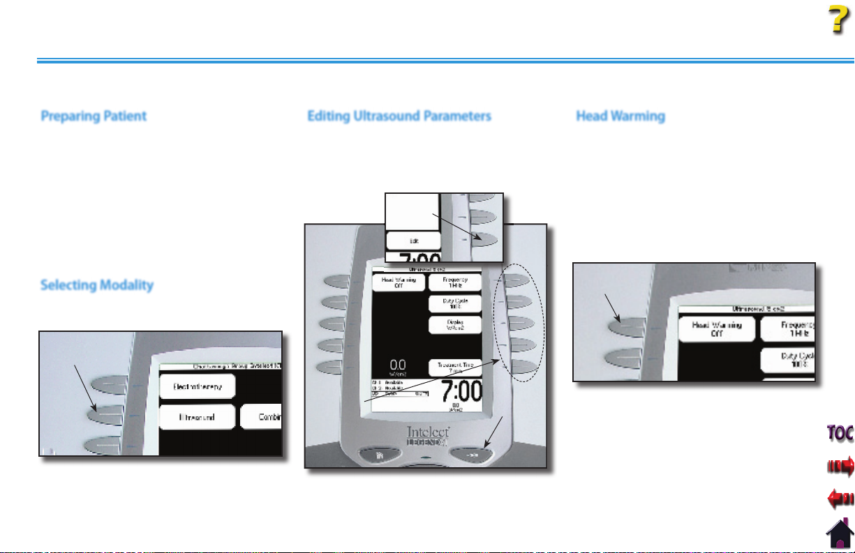
OPERATION
Intelect® Legend XT Therapy System
ULTRASOUND
The following information gives general instructions for the setup of ultrasound therapy when selecting Ultrasound from the Home screen.
Preparing Patient
Refer to page 31 for Applicator sizes,
patient preparation, and use of conductive
medium.
NOTE: Use only Intelect Legend XT
Ultrasound Applicators. Previous
models of Chattanooga Group
Ultrasound Applicators will not
work with the Intelect Legend
Editing Ultrasound Parameters
Press Edit button to access ultrasound
parameters.
Press the corresponding button to edit as
prescribed.
EDIT
BUTTON
Head Warming
The Intelect Legend XT Therapy System
incorporates a Head Warming feature that
pre-heats the Sound Head of the Applicator
for increasing patient comfort. The control
for the Head Warming feature is in the Edit
screen of the Ultrasound modality.
Press the Head Warming button until On is
displayed.
XT Therapy System.
Selecting Modality
HEAD WARMING
BUTTON
Press the Ultrasound button on the Home
screen.
ULTRASOUND
BUTTON
PARAMETER
BUTTONS
Press the Back button to return to
Treatment Review screen.
39
BACK
BUTTON
To set the default of the Head Warming
feature to On, press the Home button after
On is displayed in the Head Warming icon.
Head Warming will then start when the
Therapy System is turned On.
NOTE:
Head warming time is
approximately 2 minutes.
Page 46

OPERATION
ULTRASOUND (continued)
Setting Ultrasound Intensity
Set intensity by rotating the Intensity Control
Knob to the prescribed level.
INTENSITY
DISPLAYED
Starting Treatment
Press the Start button to begin therapy
session.
Move the Applicator in a circular motion
over the treatment area.
Intelect® Legend XT Therapy System
Pausing Treatment
Press the Pause button to pause therapy
session and maintain remaining time. To
resume treatment, press the Pause button
again.
NOTE: The Applicator LED will not illuminate
when the session has been paused.
ROTATE
INTENSITY
KNOB
Intensity Knob Rotation
Clockwise- Increases Intensity
Counterclockwise- Decreases Intensity
START
BUTTON
NOTE: When the Applicator LED is
illuminated, the Applicator is
emitting Ultrasound.
40
PAUSE
BUTTON
Page 47

OPERATION
ULTRASOUND (continued)
Intelect® Legend XT Therapy System
Stopping Treatment
To Stop treatment, press the Stop button
once. Treatment will stop and the
Completed Treatment Review screen will
display.
STOP BUTTON
Saving to Patient Data Card
After session is complete, press the Save
to Patient Card button.
through 57 for Patient Data Card Setup
and use.
Refer to pages 48
41
Page 48

OPERATION
Intelect® Legend XT Therapy System
ADJUSTING ULTRASOUND PARAMETERS DURING TREATMENT
The ultrasound parameters may be changed during a treatment session without pausing or stopping the treatment. The following
information provides instructions for changing ultrasound treatment parameters during a treatment session. The ultrasound intensity may
be increased or decreased at any time during the session without utilizing this process.
Editing Ultrasound from Home Screen
Press Select Channel button until US:
Running is framed.
Press View/Edit Channel button.
Press the Edit button on the Treatment
Review screen.
VIEW/EDIT
CHANNEL
BUTTON
SELECT
CHANNEL
BUTTON
US: RUNNING
FRAMED
EDIT
BUTTON
Press the corresponding parameter button
and edit as prescribed.
PARAMETER
BUTTONS
BACK
BUTTON
Editing Ultrasound from Treatment
Review Screen
Press the Edit button on the Treatment
Review screen.
Press the corresponding parameter button
and edit as prescribed.
EDIT
BUTTON
PARAMETER
BUTTONS
BACK
BUTTON
When editing is complete, press the Back
button to return to Treatment Review
screen.
When editing is complete, press the Back
button to return to Treatment Review
screen.
42
Page 49

OPERATION
COMBINATION
The Intelect Legend XT Therapy System Combination modality allows the user to select and use ultrasound therapy in combination with
electrical muscle stimulation.
Combination therapy utilizes the Ultrasound modality in conjunction with High Voltage Pulsed Current (HVPC), IFC (4p), IFC Premodulated
(2p), or Symmetrical Biphasic to generate a therapeutic effect. In this mode of therapy, the Sound Head of the Ultrasound Applicator
becomes one half of the electrical circuit. An electrode attached to the Black (+) Lead Wire completes the circuit.
Intelect® Legend XT Therapy System
Refer to pages 27 through 30 to
prepare patient, select electrode and
securing electrodes. Refer to page 31 for
Ultrasound patient preparation.
Connect the Black (-) Lead Wire from
Channel 2 to the electrode. Make certain
the Lead Wire is completely seated in the
electrode.
The Red (+) Lead Wire is not used. The
Ultrasound Applicator completes the
circuit for Combination Therapy.
Selecting ModalityPreparing Patient
Press the Combination button on the Home
screen.
COMBINATION
BUTTON
43
Accessing Combination Parameters
Press Edit button to access Combination
parameters.
EDIT
BUTTON
Press the Back button to return to the
Treatment Review screen.
Page 50

OPERATION
COMBINATION (continued)
Editing Ultrasound Parameters
Press the corresponding button to edit
the desired Ultrasound parameter as
prescribed.
PARAMETER
BUTTONS
NOTE: See page 39 for Head Warming
feature instructions.
Selecting Waveform
Press the Select Waveform button.
SELECT WAVEFORM
BUTTON
UP ARROW
BUTTON
ACCEPT AND
RETUN ARROW
BUTTON
DOWN ARROW
BUTTON
Press the Up or Down Arrow buttons until
the prescribed waveform is highlighted.
Press the Accept and Return Arrow button.
Intelect® Legend XT Therapy System
Using the Patient Interrupt Switch
Connect Patient Interrupt Switch to the
Therapy System. Give Patient Interrupt
Switch to patient and explain that pressing
the Red button once pauses the therapy
session.
CONNECT PATIENT
INTERRUPT SWITCH
PATIENT INTERRUPT
SWITCH
If Patient Interrupt Switch is depressed, the
treatment will be paused and a message
will appear on the System screen.
Press any button to clear the message.
NOTE: If the Patient Interrupt Switch is
depressed a second time, the
message will clear from the screen
and the treatment will remain
paused.
44
Page 51

OPERATION
COMBINATION (continued)
Editing Waveform Parameters
Press the Edit Stim button to edit the
parameters of the waveform selected.
Press the corresponding button to edit
each parameter as prescribed.
EDIT STIM
BUTTON
PARAMETER
BUTTONS
Setting Waveform Intensity
Set intensity by rotating the Intensity Control
knob to the prescribed level.
INTENSITY
DISPLAYED
ROTATE
INTENSITY
KNOB
Intensity Knob Rotation
Clockwise- Increases intensity
Counterclockwise- Decreases intensity
Intelect® Legend XT Therapy System
Setting Ultrasound Intensity
Press the Edit Ultrasound button.
Set Ultrasound intensity by rotating the
Intensity Control knob to the prescribed level.
EDIT
ULTRASOUND
BUTTON
ROTATE
INTENSITY
KNOB
Intensity Knob Rotation
Clockwise- Increases intensity
Counterclockwise- Decreases intensity
45
Page 52

OPERATION
COMBINATION (continued)
Intelect® Legend XT Therapy System
Starting Treatment
Press the Start button to begin therapy
session.
Move the Applicator in a circular motion
on the treatment area.
START
BUTTON
Pausing Treatment
Press the Pause button to pause therapy
session and maintain remaining time. To
resume treatment, press the Pause button
again.
PAUSE
BUTTON
Stopping Treatment
To Stop treatment, press the Stop button
once. Treatment will stop and the
Completed Treatment Review screen will
display.
STOP BUTTON
Saving to Patient Data Card
After session is complete, press the Save
to Patient Card button. Refer to pages 48
through 57 for Patient Data Card Setup
and use.
46
Page 53

OPERATION
Intelect® Legend XT Therapy System
ADJUSTING COMBINATION PARAMETERS DURING TREATMENT
The channel parameters may be changed during a treatment session without pausing or stopping the treatment. The following
information provides instructions for changing Combination Treatment Electrotherapy Channel and Ultrasound parameters during a
treatment session.
Editing Waveform Parameters
Press the Edit Stim button to edit the
parameters of the waveform selected.
Press the corresponding button to edit
each parameter as prescribed.
Rotate the Intensity knob to increase or
decrease waveform intensity as prescribed.
EDIT STIM
BUTTON
PARAMETER
BUTTONS
Editing Ultrasound Parameters
Press the Edit Ultrasound button.
Press the corresponding button to edit
the desired Ultrasound parameter as
prescribed.
EDIT
ULTRASOUND
BUTTON
PARAMETER
BUTTONS
NOTE: To edit parameters from the Home
screen, see page 38 for selecting
channel instructions.
NOTE:
See page 39 for Head Warming
feature instructions.
47
Page 54

OPERATION
Intelect® Legend XT Therapy System
PATIENT DATA CARD SETTING UP OF NEW CARD
General Information
The Intelect Legend XT Therapy System incorporates a Patient Data Card reading and recording device that allows transfer of patient therapy
data from the system to the card for reviewing patient modality and pain profile information. Information may be transferred to a PC via the
optional Patient Data Management System. The PC software is designed to allow easy access to patient data and printing of reports as well as
adding session notes to the Patient Data Card.
The reading and recording device allows storage and recall of the following patient session data onto the Patient Data Card: therapy session
parameters, Electrode Placement, Pain Map, Numeric Pain Scale or Visual Pain Scale, and Session Notes (stored on card via PC only). Each
Patient Data Card can store multiple sessions and each session can be recalled on the Intelect Legend XT Therapy System.
Inserting New Patient Data Card
Insert a new Patient Data Card into the
system access port as shown below. The
Therapy System will automatically format
the new Patient Data Card and a verification
message will appear.
Press any button to continue.
INSERT NEW
PATIENT DATA CARD
PRESS ANY BUTTON
TO CONTINUE
Setting up Treatment
Setup the patient's prescribed treatment.
Refer to the appropriate area of this manual
for modality setup.
Administer treatment as prescribed. When
treatment is complete, the Treatment
Review screen will be visible.
Setting up a New Patient Data Card
With new Patient Data Card inserted in
the system, press the Save to Patient Card
button.
SAVE TO
PATIENT CARD
BUTTON
48
Page 55

OPERATION
PATIENT DATA CARD SETTING UP OF NEW CARD (continued)
Entering Patient ID
Select the row of alpha or numeric
characters desired by pushing the button
beside the corresponding row. Select the
desired character in the row by pressing
the row button until the desired letter is
framed.
SELECT ROW AND CHARACTERS
When the desired character is framed, press
the Accept and Return Arrow button. The
character selected will display in the top of
the screen and the cursor will advance to
the next position.
To move back a character, press the Left
Arrow button.
CHARACTER
DISPLAYED
Intelect® Legend XT Therapy System
To delete a character, press the Left Arrow
button until the character to be deleted is
framed. Press the Delete button.
To discard entire entry, press the Back
button.
Repeat this procedure until the desired
Patient ID is entered.
After Patient ID is entered, press the Save
button.
SAVE
BUTTON
LEFT
ARROW
BUTTON
ACCEPT AND RETURN
ARROW BUTTON
NOTE: To add a space, select the area to
the left of the letter A.
49
Page 56

OPERATION
PATIENT DATA CARD SETTING UP OF NEW CARD (continued)
Accessing Electrode Placement
The following information uses an IFC
Treatment as an example. Electrode
Placement procedures for all modalities are
performed in the same basic fashion.
Press the Electrode Placement button.
ELECTRODE PLACEMENT BUTTON
Setting up Electrodes
Press the Pad button to select the Red (+) or
Black (-) electrode.
Press the Chan button to select Channel 1
or Channel 2.
Press the Side button to select Front, Back,
Left, or Right of the body graphic.
Press the Size button until desired electrode
size is displayed. If electrode desired is not
listed, select Other.
PAD
BUTTON
CHAN
BUTTON
SIDE
BUTTON
SIZE
BUTTON
Intelect® Legend XT Therapy System
Electrode Placement
Press the Up, Down, Left and Right Arrow
buttons to position the selected electrode
as close to the actual treatment location as
possible.
Press the Pad button to select the other
electrode. Repeat above procedure for
electrode positioning.
If applicable, press the Chan button, to
select another channel and repeat above
procedures.
After positioning the electrodes, press the
Accept and Return Arrow button.
ELECTRODES
POSITIONED
NOTE: When Ultrasound is the modality,
only the Side button is available.
50
ACCEPT AND RETURN
ARROW BUTTON
Page 57
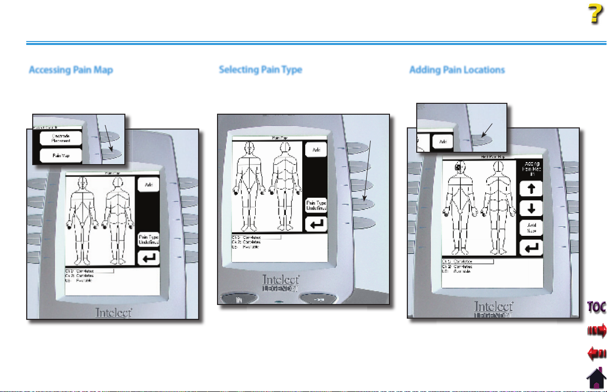
OPERATION
PATIENT DATA CARD SETTING UP OF NEW CARD (continued)
Accessing Pain Map
Press the Pain Map button to select
the body area of the associated pain as
described by the patient.
PAIN MAP BUTTON
Selecting Pain Type
Press the Pain Type button until the
desired description is displayed in the Pain
Type icon.
Intelect® Legend XT Therapy System
Adding Pain Locations
Press the Add button. The Add Pain Map
window will display.
ADD
BUTTON
PAIN TYPE
BUTTON
51
NOTE: A maximum of eight Pain Locations
may be selected.
Page 58

OPERATION
PATIENT DATA CARD SETTING UP OF NEW CARD (continued)
Selecting Location of Pain
Press the Up and Down Arrow buttons to
move the Pain Locator to the area of the
body where the pain is located.
Press the Accept and Return Arrow button.
The Pain Map window will display.
PAIN
LOCATO R
UP AND DOWN
ARROW BUTTONS
ACCEPT AND RETURN
ARROW BUTTON
Press the Add button to continue selecting,
in sequence, the radiating path of the pain
using the above procedure.
Up to eight pain locations may be selected.
BUTTON
After all desired Pain Locations have been
made, press the Back button.
ADD
BACK
BUTTON
Intelect® Legend XT Therapy System
Editing Pain Locations
Press the Edit button on the Pain Map
window.
EDIT
BUTTON
UP AND DOWN
ARROW BUTTONS
EDIT NEXT
BUTTON
ACCEPT AND RETURN
ARROW BUTTON
Press the Edit Next button to highlight the
Pain Location to be edited.
Use the Up and Down Arrow buttons to
relocate the selected Pain Location.
Press the Accept and Return Arrow button.
Repeat until all editing is complete, then
press the Back button.
52
Page 59
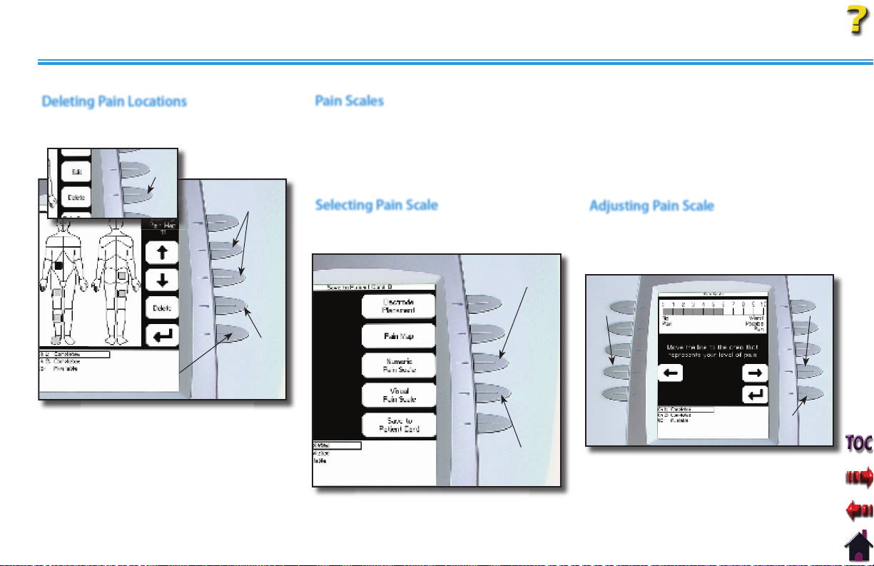
OPERATION
PATIENT DATA CARD SETTING UP OF NEW CARD (continued)
Deleting Pain Locations
Press the Delete button on the Pain Map
window.
DELETE
BUTTON
UP AND DOWN
ARROW BUTTONS
DELETE
BUTTON
ACCEPT AND RETURN
ARROW BUTTON
Pain Scales
The Intelect Legend XT Therapy System incorporates two internationally recognized
Pain Scales; VAS ( Visual Analog Scale), which has no indicator marks and Numeric Scale
(indicated 1 through 10). Use either of these for describing the amount of pain the patient
is experiencing. When either pain scale is set, the other will automatically set to the
corresponding level.
Selecting Pain Scale
Select the desired Pain Scale by pressing the
corresponding button.
NUMERIC PAIN
SCALE BUTTON
Intelect® Legend XT Therapy System
Adjusting Pain Scale
Press the Left and Right Arrow buttons to
adjust the Pain Scale to the level the patient
is experiencing.
LEFT
ARROW
BUTTON
RIGHT
ARROW
BUTTON
Use the Up and Down Arrow buttons to
highlight the Pain Location to be deleted.
Press the Delete button.
Press the Accept and Return Arrow button.
Repeat until all editing is complete, then
press the Back button.
53
VISUAL PAIN
SCALE BUTTON
ACCEPT AND RETURN
ARROW BUTTON
After the desired level is achieved, press the
Accept and Return Arrow button.
Numeric Pain Scale illustrated.
NOTE:
Page 60

OPERATION
PATIENT DATA CARD SETTING UP OF NEW CARD (continued)
Saving to Patient Data Card
After all desired session data has been
entered in the Patient Data Card screens,
press the Save to Patient Card button. A
message will appear stating the data has
been saved to the Patient Data Card.
Press any button.
SAVE TO PATIENT
CARD BUTTON
After pressing any button, the Completed
Treatment Review screen will display.
Press the Home button.
Remove the Patient Data Card for filing with
patient records.
The Patient Data Card can also be used with
the optional Patient Data Management
System.
Intelect® Legend XT Therapy System
54
Page 61

OPERATION
EXISTING PATIENT DATA CARD USE
Inserting Existing Patient Data Card
Insert the Patient Data Card assigned to the
patient receiving treatment into the system
access port as shown below.
INSERT EXISTING
PATIENT DATA CARD
Accessing Patient Data Card
Press the Patient Card button to access
Patient Data Card.
Select the date of the treatment session
desired using the Up and Down Arrow
buttons until date desired is highlighted.
PATIENT CARD
BUTTON
UP ARROW
BUTTON
DOWN ARROW
BUTTON
Intelect® Legend XT Therapy System
Viewing Patient Data Card
Press the corresponding button beside the
Patient Data to be viewed.
NOTE: No Session Notes will be
available unless the optional
Patient Data Management System
was utilized to enter Session Notes
onto the Patient Data Card.
55
Page 62

OPERATION
EXISTING PATIENT DATA CARD USE (continued)
Starting a New Treatment from Patient
Data Card
Refer to pages 27-30 for Electrotherapy
patient preparation, select electrodes, and
secure electrodes. Refer to page 31 for
Ultrasound patient preparation.
Press the Up and Down Arrow buttons to
highlight the desired treatment date and
time.
Press the View Treat button.
Press Start New Treatment button.
VIEW TREAT
BUTTON
START NEW
TREATMENT
BUTTON
Using the Patient Interrupt Switch
Connect Patient Interrupt Switch to the
Therapy System. Give Patient Interrupt
Switch to patient and explain that pressing
the Red button once pauses the therapy
session.
CONNECT PATIENT
INTERRUPT SWITCH
If Patient Interrupt Switch is depressed, the
treatment will be paused and a message
will appear on the System screen.
Press any button to clear the message.
NOTE: If the Patient Interrupt Switch is
depressed a second time, the
message will clear from the screen
and the treatment will remain
paused.
PATIENT
INTERRUPT
SWITCH
Intelect® Legend XT Therapy System
Setting Intensity
Set intensity by rotating the Intensity Control
Knob to the prescribed level.
INTENSITY
DISPLAYED
ROTATE
INTENSITY
KNOB
Intensity Knob Rotation
Clockwise- Increases Intensity
Counterclockwise- Decreases Intensity
56
Page 63

OPERATION
EXISTING PATIENT DATA CARD USE (continued)
Intelect® Legend XT Therapy System
Starting Treatment
Press the Start button to begin therapy
session.
START
BUTTON
Pausing Treatment
Press the Pause button to pause therapy
session and maintain remaining time. To
resume treatment, press the Pause button
again.
PAUSE
BUTTON
Stopping Treatment
To Stop treatment, press the Stop button
once. Treatment will stop and the
Completed Treatment Review screen will
display.
STOP BUTTON
Erasing Patient Data Card
Refer to page 23 for proper Patient Data
Card Erasing instructions.
57
Page 64

OPERATION
Intelect® Legend XT Therapy System
CREATING USER PROTOCOLS
General Information
This library is a series of protocols created by the user and stored in the system memory. The following information gives general instructions as
to setting up, saving and accessing User Protocols. Should the Default Protocols be restored, through the User Utilities, all User Protocols will be
permanently removed from the system.
The Therapy System memory will accommodate up to 200 user defined protocols.
Selecting Modality
Press the button beside the desired
modality on the Home screen or select a
User Protocol using the Clinical Resources
Library button.
MODALITY BUTTONS
CLINICAL RESOURCES
LIBRARY BUTTON
Editing Modality Parameters
Press the modality Edit button (usually
in the lower right corner of the modality
Treatment Review screen) and edit as
prescribed.
Refer to respective sections of this manual
for the specific modality prescribed.
EDIT
BUTTON
58
Selecting Clinical Resources Library
Press the Clinical Resources Library button
to begin the save process of the new User
Protocol.
Page 65

OPERATION
CREATING USER PROTOCOLS (continued)
Entering User Protocol Name
Select the row of alpha or numeric
characters desired by pushing the button
beside the corresponding row. Select the
desired character in the row by pressing
the row button until the desired letter is
framed.
SELECT ROW AND CHARACTERS
When the desired character is framed, press
the Accept and Return Arrow button. The
character selected will display in the top of
the screen and the cursor will advance to
the next position.
To move back a character, press the Left
Arrow button.
CHARACTER
DISPLAYED
Intelect® Legend XT Therapy System
To delete a character, press the Left Arrow
button until the character to be deleted is
framed. Press the Delete button.
To discard entire entry, press the Back
button.
Repeat this procedure until the desired
Patient ID is entered.
After Patient ID is entered, press the Save
button.
SAVE
BUTTON
LEFT
ARROW
BUTTON
ACCEPT AND RETURN
ARROW BUTTON
NOTE: To add a space, select the area to
the left of the letter A.
59
Page 66

OPERATION
Intelect® Legend XT Therapy System
DELETING USER PROTOCOLS
General Information
The following information provides instructions for the deletion of one User Protocol at a time. Once any single User Protocol is deleted, it
cannot be recovered. Should the Default Protocols be restored through the User Utilities, all User Protocols will be permanently removed from
Deleting User Protocols
the system.
There is no method for recovery of the User Protocols nor can they be saved to any other medium.
Selecting Clinical Resources Library
Press the Clinical Resources Library button.
Then press the User Protocols button.
USER
PROTOCOLS
BUTTON
Selecting User Protocol to Delete
Press the UP and Down Arrow buttons until the
desired User Protocol to delete is highlighted.
UP AND DOWN
ARROW BUTTONS
60
Deleting User Protocol
Press the Delete button to delete highlighted
User Protocol.
A verification screen will appear. Press Yes
button to delete protocol or No button to keep
protocol.
DELETE
BUTTON
NO
BUTTON
YES
BUTTON
Repeat this process until all desired User
Protocols are deleted.
Press the Home button to return to the Home
screen.
Page 67

OPERATION
USING USER PROTOCOLS
Accessing User Protocols
Press the Clinical Resources Library button.
Press the User Protocols button.
Selecting User Protocol
Press the UP and Down Arrow buttons until the
prescribed User Protocol is highlighted.
Press the Accept and Return Arrow button.
UP ARROW
BUTTON
Intelect® Legend XT Therapy System
Preparing Patient
Refer to pages 27 through 30 for
Electrotherapy and page 31 for Ultrasound
patient preparation instructions.
Editing Modality Parameters
Press the Edit button.
Edit modality parameters as prescribed.
Refer to page 35 for Electrotherapy
modalities and page 39 for Ultrasound.
EDIT
BUTTON
USER
PROTOCOLS
BUTTON
ACCEPT AND
RETURN ARROW
BUTTON
61
DOWN ARROW
BUTTON
Page 68

OPERATION
USING USER PROTOCOLS (continued)
Using the Patient Interrupt Switch
Make certain the Patient Interrupt Switch,
for the channel(s) being used, is connected
to the Therapy System.
Symbol Definitions.
PATIENT
INTERRUPT
SWITCH
Refer to page 13 for
LANYARD
Give Patient Interrupt Switch to patient
and explain that pressing the Red button
once pauses the therapy session.
PRESSING BUTTON ONCE PAUSES SESSION
If Patient Interrupt Switch is depressed, the
treatment will be paused and a message
will appear on the System screen.
Press any button to clear the message.
Intelect® Legend XT Therapy System
Setting Modality Intensity
Set intensity by rotating the Intensity Control
Knob to the prescribed level.
INTENSITY
DISPLAYED
ROTATE
INTENSITY
KNOB
Intensity Knob Rotation
Clockwise- Increases Intensity
Counterclockwise- Decreases Intensity
NOTE: When reinstalling the Front Access
Panel, make certain the Lanyard does
not become kinked.
NOTE: If the Patient Interrupt Switch is
depressed a second time, the
message will clear from the
screen and the treatment will
remain paused.
62
Page 69

OPERATION
USING USER PROTOCOLS (continued)
Intelect® Legend XT Therapy System
Starting Treatment
Press the Start button to begin therapy
session.
START
BUTTON
NOTE: Modality parameters may be
edited at any time during the
therapy session.
Refer to page
48 for Electrotherapy and page 52
for Ultrasound.
Pausing Treatment
Press the Pause button to pause therapy
session and maintain remaining time. To
resume treatment, press the Pause button
again.
PAUSE
BUTTON
Stopping Treatment
To Stop treatment, press the Stop button
once. Treatment will stop and the
Completed Treatment Review screen will
display.
STOP BUTTON
Saving to Patient Data Card
After session is complete, press the Save
to Patient Card button. Refer to pages 48
through 57 for Patient Data Card Setup
and use.
63
Page 70
INSTALLATION/REMOVAL
INSTALLING THE CHANNEL 3/4 ELECTROTHERAPY AND NiMH BATTERY MODULE
Possible System Configurations
The Intelect Legend XT Electrotherapy and Combination Systems allow installation of optional modality modules by the user. Specifically
designed for use with the Intelect Legend XT Therapy Systems, these modules configure the Therapy System to meet many of the therapeutic
needs that a clinician may have. The following is a list of possible configurations of the Intelect Legend XT Therapy System.
• Four Channel Electrotherapy or Combination System: Install the Channel 3/4 Electrotherapy Module to the Two Channel Electrotherapy
or Combination System.
• Battery Powered Two Channel Electrotherapy or Combination System: Install the NiMH Battery Module.
NOTE: The Battery Module cannot be installed on a Four Channel System. The Channel 3/4 Electrotherapy must first be removed.
The Channel 3/4 Electrotherapy and NiMH Battery modules are shipped with all necessary lead wires and accessories in order to complete the
installation and allow immediate use by a physician or licensed practitioner.
No special tools or equipment are required for optional Module installation. The System is programmed to automatically recognize the new
Module(s), therefore, no software installation is required.
This section explains user installation procedures for the following modules: Channel 3/4 Electrotherapy Module and NiMH Battery Module.
Intelect® Legend XT Therapy System
64
Page 71

INSTALLATION/REMOVAL
INSTALLING THE CHANNEL 3/4 ELECTROTHERAPY AND NiMH BATTERY MODULE (continued)
Nomenclature- Channel 3/4 Electrotherapy Module
5
4
1
3
1. Extended Front Access Panel
2. Module to System Mounting Holes
3. Module to System Feet Alignment Indents
4. Power Cord Routing Port
5. Module to System Connector
6. Operator Remote Control Connector*
7. Patient Interrupt Switch Connector*
8. Channel 3 Lead Wire Connector*
9. Channel 4 Lead Wire Connector*
10. Microcurrent Probe Connector*
Intelect® Legend XT Therapy System
2
6
7
8
9
10
Also Included:
Four 4 mm X 20 mm mounting screws
•
Channel 3 and 4 Lead Wires
•
Patient Interrupt Switch (Ch 3/4)
•
Carbon Electrodes
•
Sample of DURA-STICK™ II electrodes
•
®
Nylatex
•
Wraps
* Refer to page 13 for Symbol Definitions.
65
Page 72

INSTALLATION/REMOVAL
INSTALLING THECHANNEL 3/4 ELECTROTHERAPY AND NiMH BATTERY MODULE (continued)
Specifications
HEIGHT
DEPTH
WIDTH
DIMENSIONS
Width . . . . . . . . . . . . . . . . . . . . . . . . . . . . . . . . . . . . . . . . . . . 8.250 in (21 cm)
Depth . . . . . . . . . . . . . . . . . . . . . . . . . . . . . . . . . . . . . . . . . . 11.875 in (30 cm)
Height . . . . . . . . . . . . . . . . . . . . . . . . . . . . . . . . . . . . . . . . 4.500 in (11.5 cm)
WEIGHT
Standard Weight . . . . . . . . . . . . . . . . . . . . . . . . . . . . . . . . . . 1.0 lbs (.50 kg)
POWER
Input . . . . . . . . . . . . . . . . . . . . . . . . . . . . . . . . . . . . . . . . .System Dependent
Output . . . . . . . . . . . . . . . . . . . . . . . . . . . . . . . . . . . . . . .System Dependent
Electrical Class . . . . . . . . . . . . . . . . . . . . . . . . . . . . . . . . . . . . . . . . . . . .CLASS I
Electrical Type . . . . . . . . . . . . . . . . . . . . . . . . . . . . . . . . . . . . . . . . TYPE BF
Regulatory Compliance
UL/IEC/EN 60601-1
IEC 60601-2-10
Intelect® Legend XT Therapy System
NOTE: All waveforms except High Voltage Pulsed Current (HVPC) of
the Intelect Legend XT Therapy System have been
designed with a 200 mA current limit. TENS waveform
output intensities are measured, specified and listed to peak,
not peak to peak.
0413
Waveform & Current Specifications
All waveform/currents available to the Intelect Legend XT
Therapy System are available to the Channel 3/4 Electrotherapy
Module once installation is complete. Refer to pages 16 through
18 for available waveform specifications.
66
Page 73

INSTALLATION/REMOVAL
INSTALLING THE CHANNEL 3/4 ELECTROTHERAPY AND NiMH BATTERY MODULE (continued)
Disconnecting Mains Power
Disconnect the system from the
power source (outlet or remove battery
module if installed) before attempting
any maintenance, installation, removal, or
replacement procedures to prevent electrical
shock and possible damage to the system.
Disconnect the Mains Power Cord from
the power supply. Remove the Rear Access
Panel and disconnect the Mains Power
Cord from the Therapy System.
REAR
ACCESS
PAN EL
Removing Lead Wires and Accessories
Remove the Front Access Cover and
disconnect the Lead Wires and Accessories
from the Therapy System.
REMOVE LEAD
WIRES AND
ACCESSORIES
Removing Therapy System from Cart
Remove the Therapy System from the
Therapy System Cart, if equipped. Refer
to
pages 78 through 79 for proper
instructions.
Place Therapy System face down on a clean
working surface protected with a soft, clean
fabric to prevent damage to the lens.
Intelect® Legend XT Therapy System
MAINS
POWER
CORD
LANYARD
67
Page 74

INSTALLATION/REMOVAL
INSTALLING THE CHANNEL 3/4 ELECTROTHERAPY AND NiMH BATTERY MODULE (continued)
Releasing Ribbon Cable
Remove and discard the vinyl label holding
the Ribbon Cable in the cavity on the
Therapy System.
Carefully unroll the Ribbon Cable, making
certain not to disconnect it from the
Therapy System.
CAREFULLY UNROLL
RIBBON CABLE
Positioning Therapy System and Module
Position Therapy System and the Channel
3/4 Electrotherapy Module as shown.
Connecting Ribbon Cable
Carefully align the Ribbon Cable Connector
to the Module Connector Pins and press
down to connect.
Intelect® Legend XT Therapy System
68
NOTE: Ribbon Cable must be connected
as shown!
Make certain Ribbon Cable is completely
seated to Module Connector Pins.
Page 75
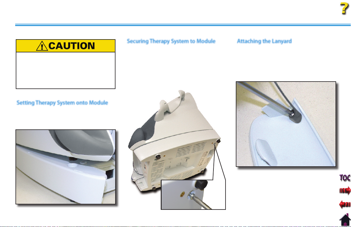
INSTALLATION/REMOVAL
INSTALLING THE CHANNEL 3/4 ELECTROTHERAPY AND NiMH BATTERY MODULE (continued)
Do not twist Ribbon Cable. If power is
applied to the system with misalignment
of pins or a twisted ribbon cable, the
controlling electronics in the Module will
be destroyed and possible damage to the
System's internal components could occur.
Setting Therapy System onto Module
Set the Therapy System on the Module.
Make certain the Feet of the Therapy
System are resting in the Module Indents.
Securing Therapy System to Module
Carefully place the Therapy System and
Module on one side. With a #1 Phillips
Screwdriver, install the four 4 mm x 20 mm
screws.
Tighten screws until the Module does not
move on the Therapy System.
Attaching the Lanyard
With a #1 Phillips Screwdriver, remove the
screw retaining the existing Front Access
Panel.
Install Lanyard to the new Extended Front
Access Panel using the same screw.
Intelect® Legend XT Therapy System
69
Page 76

INSTALLATION/REMOVAL
Intelect® Legend XT Therapy System
INSTALLING THE CHANNEL 3/4 ELECTROTHERAPY AND NiMH BATTERY MODULE (continued)
Installing Lead Wires and Accessories Connecting Mains Power
Install Lead Wires and additional accessories
to Front Panel.
Refer to page 13 for Symbol
Definitions.
Installing Front Access Panel
Install the new Extended Front Access Panel
onto Therapy System.
Make certain Lanyard does not become
kinked.
LANYARD
Connect the Mains Power Cord to the
Therapy System.
Install Rear Access Panel.
Connect the Mains Power Cord to an
approved power source.
MAINS
POWER
CORD
Mounting to Therapy System Cart
If mounting Therapy System to a Therapy
System Cart, refer to pages 78 through 79
for instructions.
REAR
ACCESS
PANEL
70
Page 77

INSTALLATION/REMOVAL
INSTALLING THE CHANNEL 3/4 ELECTROTHERAPY AND NiMH BATTERY MODULE (continued)
Turning Therapy System On
Turn the System On using the On/Off
Switch. The System will automatically
recognize the added Module and display a
configuration change message.
Read and carefully follow the instructions
on the screen.
Verify that the Module installed is the Module
displayed in the message BEFORE pressing
the START button. If it is not, DO NOT press
the START button. Turn the System OFF and
back ON. If the problem continues, call the
selling dealer or Chattanooga Group Technical
Support immediately.
DO NOT USE THE SYSTEM until all necessary
repairs are made by a Technician certified
by Chattanooga Group. If use is attempted
before repairs are made, the System may
operate unpredictably and has the potential
of causing injury to the patient or damage to
the System's internal components.
Intelect® Legend XT Therapy System
71
Page 78
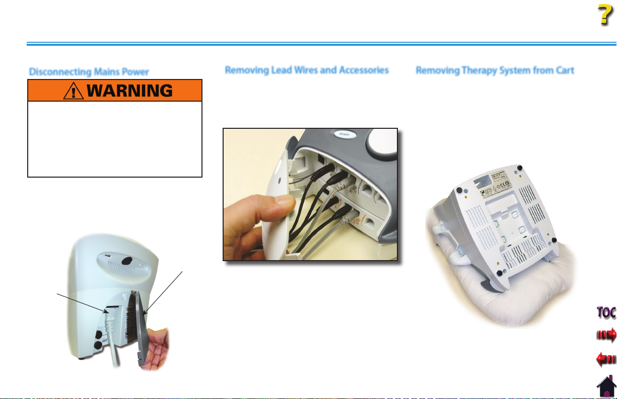
INSTALLATION/REMOVAL
REMOVING THE CHANNEL 3/4 ELECTROTHERAPY AND NiMH BATTERY MODULE
Disconnecting Mains Power
DISCONNECT THE SYSTEM FROM THE POWER
SOURCE (OUTLET OR REMOVE BATTERY
MODULE IF INSTALLED) BEFORE ATTEMPTING
ANY MAINTENANCE, INSTALLATION,
REMOVAL, OR REPLACEMENT PROCEDURES
TO PREVENT ELECTRICAL SHOCK AND
POSSIBLE DAMAGE TO SYSTEM.
Disconnect the Mains Power Cord from
the power supply. Remove the Rear Access
Panel and disconnect the Mains Power
Cord from the Therapy System.
REAR
ACCESS
PAN EL
Removing Lead Wires and Accessories
Remove the Front Access Cover and
disconnect the Lead Wires and Accessories
from the Therapy System and Channel 3/4
Electrotherapy Module.
REMOVE LEAD
WIRES AND
ACCESSORIES
Intelect® Legend XT Therapy System
Removing Therapy System from Cart
Remove the Therapy System from the
Therapy System Cart, if equipped. Refer
to pages 78 through 79
for proper
instructions.
Place Therapy System face down on a clean
working surface protected with a soft, clean
fabric to prevent damage to the lens.
MAINS
POWER
CORD
NOTE: Keep Lead Wires and accessories
for later re-installation to the
Therapy System.
72
Page 79

INSTALLATION/REMOVAL
REMOVING THE CHANNEL 3/4 ELECTROTHERAPY AND NiMH BATTERY MODULE (continued)
Removing Screws Securing Module
With a #1 Phillips Screwdriver, remove the
four 4 mm x 20 mm screws securing the
Module to the Therapy System.
Disconnecting Ribbon Cable at Module
Separate the Module from the Therapy
System and disconnect the Ribbon Cable
from the Module Connector Pins.
Do not disconnect Ribbon Cable from
the Therapy System.
DISCONNECT
RIBBON FROM
MODULE ONLY
Storing and Securing Ribbon Cable
Roll the Ribbon Cable up and store in
the cavity of the Therapy System. Secure
Ribbon Cable with a nonpermanent
adhesive tape.
Intelect® Legend XT Therapy System
73
Page 80

INSTALLATION/REMOVAL
REMOVING THE CHANNEL 3/4 ELECTROTHERAPY AND NiMH BATTERY MODULE (continued)
Attaching the Lanyard
With a #1 Phillips Screwdriver, remove the
screw retaining the existing Front Access
Panel.
Install Lanyard to the original Front Access
Panel using the same screw.
Installing Lead Wires and Accessories Connecting Mains Power
Re-install Lead Wires and Accessories to the
Therapy System Front Panel.
Connect the Mains Power Cord to the
Therapy System.
Install Rear Access Panel.
LANYARD
Connect the Mains Power Cord to an
approved power source.
MAINS
POWER
CORD
NOTE: When re-installing the Front Access
Panel to the Therapy System, make
certain the Lanyard does not become
kinked.
Intelect® Legend XT Therapy System
REAR
ACCESS
PANEL
74
Page 81

INSTALLATION/REMOVAL
REMOVING THE CHANNEL 3/4 ELECTROTHERAPY AND NiMH BATTERY MODULE (continued)
Turning Therapy System On
Turn the System On using the On/Off
Switch. The System will automatically
recognize the Module has been removed
and will display a configuration change
message.
Read and carefully follow the instructions
on the screen.
Verify that the Module installed is the Module
displayed in the message BEFORE pressing
the START button. If it is not, DO NOT press
the START button. Turn the System OFF
and back ON. If the problem continues, call
the selling dealer or Chattanooga Group
Technical Support immediately.
DO NOT USE THE SYSTEM until all necessary
repairs are made by a Technician certified
by Chattanooga Group. If use is attempted
before repairs are made, the System may
operate unpredictably and has the potential
of causing injury to the patient or damage to
the System's internal components.
Intelect® Legend XT Therapy System
75
Page 82
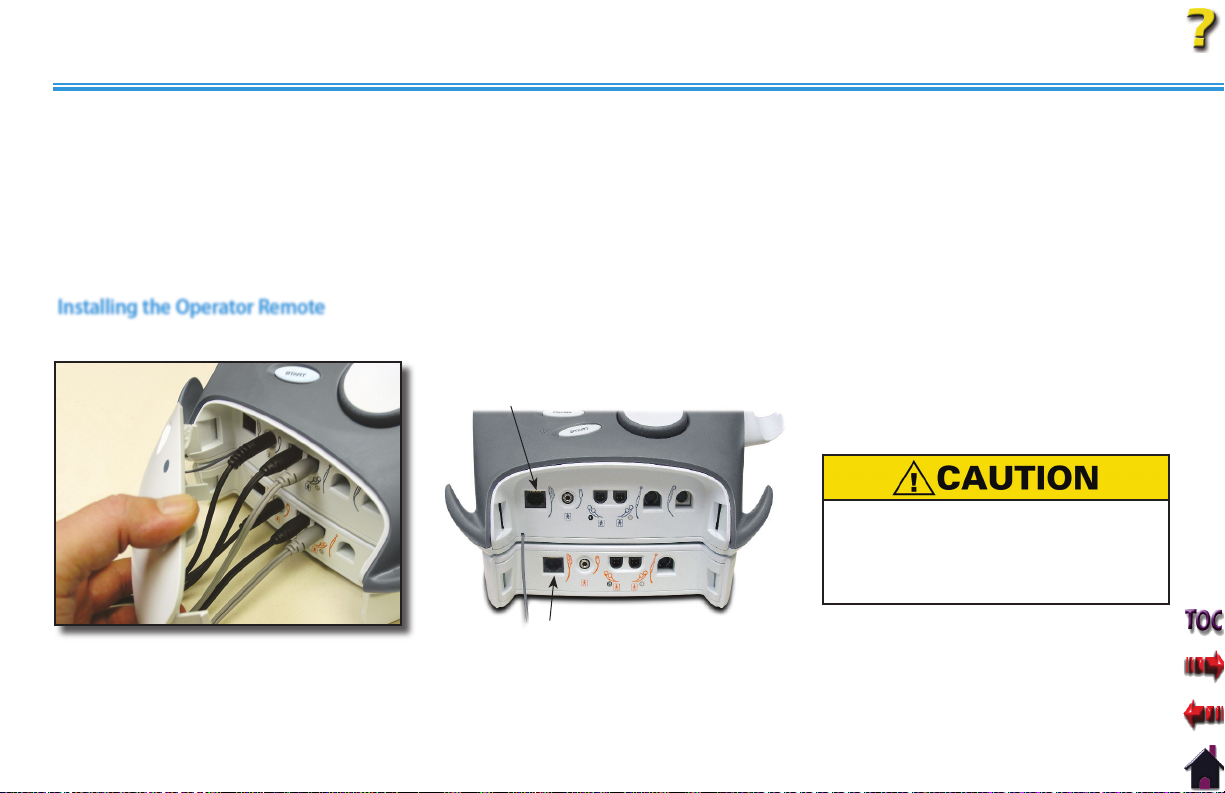
INSTALLATION/REMOVAL
GENERAL INFORMATION OPERATOR REMOTE
The Optional Operator Remote is designed for use with the Intelect Legend XT Electrotherapy and Combination Systems only and allows
the operator to control the application of manual muscle stimulation therapy as well as increase and decrease the waveform intensity.
There are two different Operator Remotes. One is designed for use with Channels 1 and 2. It is designated by a blue Pause Button on the
control. The other is designed for use on channels 3 and 4 (Systems with the optional Channel 3/4 Electrotherapy Module installed) and
is designated with an orange color Pause Button. Make certain the remote for the channels being used is connected to the respective
System or Module before administering any therapy with the Operator Remote.
Installing the Operator Remote
Connect the Operator Remote into its
Remove the Front Access Panel.1.
2.
respective jack.
CHANNEL 1/2 OPERATOR
REMOTECHANNEL 3/4 OPERATOR REMOTE
NOTE: If the System is equipped with the
Channel 3/4 Electrotherapy
Module, the Channel 3/4 User
remote will be installed into the
respective jack on the Module.
Operator Remote is to be used under
supervision of a physician or licensed
practitioner only. The Operator Remote
is not intended for patient use.
Intelect® Legend XT Therapy System
Reinstall the System Front Access
3.
Panel.
76
Page 83

INSTALLATION/REMOVAL
Intelect® Legend XT Therapy System
GENERAL INFORMATION THERAPY SYSTEM CART
The optional Therapy System Cart is designed for use with the Intelect Legend XT Electrotherapy and Combination Systems only and allows the
user to easily transport the System from patient to patient within the clinic as well as store all necessary accessories, supplies and applicators used
for the various modalities of the System.
The following instructions will explain the proper installation of the Intelect Legend XT Therapy System, with and without optional modules, to a
Therapy System Cart.
Nomenclature
6
5
4
Specifications
Front and Rear
1.
Extrusion
Cart Base
2.
Front Locking
3.
Swivel Casters
(2)
Rear Swivel
4.
Casters (2)
1
Removable
5.
Storage
Bins (6)
Cart Top
6.
2
3
Dimensions
Height
Cart Only . . . . . . . . . . . 33.75 in (85.7 cm)
With System . . . . . . . . 42.50 in (108 cm)
With System and Module . . . . . .44.25 in
(112.4 cm)
Width . . . . . . . . . . . . . . . . . . . 17 in (43.2 cm)
Depth . . . . . . . . . . . . . . . . 16.25 in (41.3 cm)
Standard Weight . . . . . . . . . 24 lbs (10.9 kg)
Shipping Weight . . . . . . . . . . 33 lbs (15.0 kg)
Power Required. . . . 100 - 240 V, 50/60 Hz
DEPTH
WIDTH
HEIGHT
CART ONLY
HEIGHT
WITH SYSTEM & SYSTEM WITH MODULE
77
Page 84

INSTALLATION/REMOVAL
MOUNTING THERAPY SYSTEM TO THERAPY SYSTEM CART
Assembling the Therapy System Cart
Follow the "Assembling Therapy System
Cart" instructions shipped with the Cart for
proper assembly. If the instruction sheet is
not available visit the Chattanooga Group
website, www.chattgroup.com, to obtain a
copy of the instruction sheet.
Preparing the Therapy System Cart
Remove all the Storage Bins from both
sides of the Therapy System Cart by pulling
each bin out and up.
REMOVE
ALL BINS
Allow approximately 4.5 in (11.5 cm) of
the power cord extending through the
top of the cart for connecting to system.
If the system is equipped with an optional
NiMH Battery, Laser or Channel 3/4
Electrotherapy Module, it will be necessary
to allow 6.5 in (16.5 cm) of the Power Cord
extending through the top of the Therapy
System Cart.
4.5 IN 11.5 CM
SYSTEM ONLY
6.5 IN 16.5 CM
SYSTEM W/MODULE
Intelect® Legend XT Therapy System
Mounting the Therapy System to Cart
Position the Therapy System onto the
Therapy System Cart with the rear of the
System over the Mains Power Cord.
Secure the System to the cart with the four
socket head screws in the Therapy System
Cart Top.
HAND TIGHTEN THE SOCKET
HEAD SCREWS TO SECURE
SYSTEM TO CART
NOTE: Secure the System to the cart by
tightening the screws by hand
only. Do not use a wrench to
tighten the screws. Overtightening
may cause damage to the System
or Module housing.
78
Page 85

INSTALLATION/REMOVAL
MOUNTING THERAPY SYSTEM TO THERAPY SYSTEM CART (continued)
Connecting Mains Power
Plug Power Cord into the System Mains
Disconnect and reinstall the Rear Access
Panel. Install all lead wires and cables to
the System.
CONNECT
MAINS POWER
CORD
Installing Storage Bins
Install Storage Bins into Therapy System
Cart. Start with bottom Storage Bin first.
Intelect® Legend XT Therapy System
Removing System from Therapy
System Cart
To remove the Therapy System from the
Therapy System Cart, repeat the Mounting
instructions.
79
Page 86

OPTION OPERATION
USING THE OPERATOR REMOTE
Nomenclature Operation
7
6
4
5
* BLUE FOR CHANNELS 1/2 OPERATOR REMOTE
ORANGE FOR CHANNELS 3/4 OPERATOR REMOTE
1. Remote Storage Hook
2. Treatment Pause Button
3. Channel 2 Increase Intensity Button
4. Channel 2 Decrease Intensity Button
5. Manual Stimulation Button
6. Channel 1 Decrease Intensity Button
7. Channel 1 Increase Intensity Button
NOTE:
Refer to page 13 for Symbol
Definitions.
1
Operator Remote is to be used under
supervision of a physician or licensed
practitioner only.
The Operator Remote is not intended for
2*
3
patient use.
Install the Operator Remote as described
on page 76. Set up electrotherapy session
as described on pages 35-37.
Start electrotherapy session by pressing the
Start Treatment Button.
STOP
TREATMENT
BUTTON
START
TREATMENT
BUTTON
Intelect® Legend XT Therapy System
Pause session by pressing the Pause Button
on the Remote being used.
Press the M Button on the remote to apply
Manual Stimulation. Release the M Button
to stop Manual Stimulation application.
Increase or Decrease the intensity by
pressing the Up or Down Button on the
Operator Remote for the respective channel
being used. This can be done while Manual
Stimulation is being applied.
To Stop session, press the Stop Treatment
Button.
Verify each Operator Remote is
connected to the applicable jack for the
channels being used.
80
Page 87
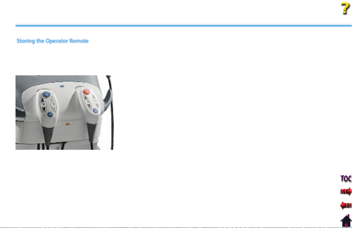
OPTION OPERATION
USING THE OPERATOR REMOTE (continued)
Storing the Operator Remote
Normal storage of the Operator Remote is
on the Front Access Panel of the System.
Place the storage hook into one of the
Remote Storage Indents as shown.
Intelect® Legend XT Therapy System
81
Page 88
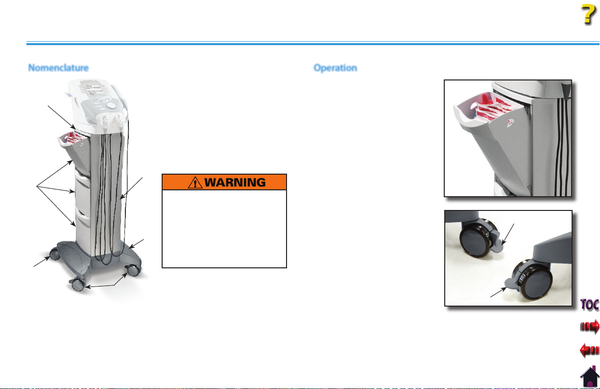
OPTION OPERATION
USING THE THERAPY SYSTEM CART
Nomenclature Operation
Front and Rear Extrusion
1.
Cart Base
6
2.
Front Locking Swivel
3.
Casters (2)
Rear Swivel Casters (2)
4.
Removable Storage Bins (6)
5.
Cart Top
6.
1
5
Make certain the unit
is electrically grounded
by connecting only to a
grounded electrical service
2
receptacle conforming to
the applicable national and
4
3
3
local electrical codes.
1. Install the Therapy System
Cart as described on pages
78 through 79.
2. Open Storage Bins and place
items for storage. Close Bins
until they snap into position.
3. Lock the Front Locking Swivel
Casters by pushing Lock
down with toe of shoe.
Unlock by pulling Lock up
with toe of shoe.
Intelect® Legend XT Therapy System
DOWN TO LOCK
UP TO UNLOCK
82
Page 89

OPTION OPERATION
Intelect® Legend XT Therapy System
USING THE NIMH BATTERY MODULE
The Intelect Legend XT Battery Module allows easy upgrade of the Intelect® Legend XT Electrotherapy and Combination Systems to create a
battery powered Therapy System. The information in this section instructs the owner, operator or user as to the initial setup and operation of
the optional NiMH Battery Module. No additional Software is required for the Module as the System automatically recognizes its presence and
activates all necessary software inherent in the System.
Read, understand and follow all Safety Precautions on
pages 2 through 9 and throughout this manual before operating this Therapy
System, Modules or Accessories.
Nomenclature
6
5
1
1. Battery Module
2. Extended Front Access Panel
3. Module to System Mounting Holes
2
4. Module to System Feet Alignment Indents
5. Power Cord Routing area
6. Ribbon Cable Connector
4
3
83
Page 90

OPTION OPERATION
CHARGING BATTERY MODULE
Use the following instructions to properly
charge the Intelect® Legend XT Battery
Module for use.
When to Recharge
Charging of the Battery Module is required
when the Battery Indicator begins flashing.
When charging Battery Module,
certain the System is electrically grounded
by connecting only to a grounded
electrical service receptacle conforming to
the applicable national and local electrical
codes. Using any other power source
will cause extensive damage to internal
components and render the System
unsafe for patient therapy.
With Battery Module installed on the
Intelect Legend XT Therapy System, plug
the System into an approved, grounded
power outlet.
Turn the System on. The Lightning Bolt
icon will display indicating the battery
is charging. As the battery charges, the
Battery indicator icon will progressively fill
until it is solid black indicating full charge.
make
BATTERY
LIGHTNING
BOLT ICON
INDICATOR
ICON
NOTE: The Lightning Bolt icon will
continue to display as long as the
System is connected to a power
source.
Charge the battery according to the
•
instructions found in this manual.
Never attempt to charge the battery
on any other charging mechanism.
Use the Battery Module only with the
•
Intelect Legend XT Therapy System.
Do not reverse the polarity of the
•
Battery Module. Doing so can increase
the individual cell temperature and
cause cell rupture or leakage.
Intelect® Legend XT Therapy System
Charging Temperature
Charging efficiency is optimum within a
•
temperature range of 50 °F to 86 °F (10
°C to 30 °C). Charge the Battery Module
within this temperature range.
At temperatures below 32 °F (0 °C) the
•
gas absorption reaction is not sufficient
and causes an increase of the gas
pressure inside the battery. This condition
can activate the safety vent and lead
to alkaline gas leaking and battery
performance deterioration.
Charging efficiency of the Battery Module
•
drops at temperatures above 104 °F
(40 °C) and can disrupt full charging,
lead to deterioration in performance and
battery cell leakage.
84
Page 91
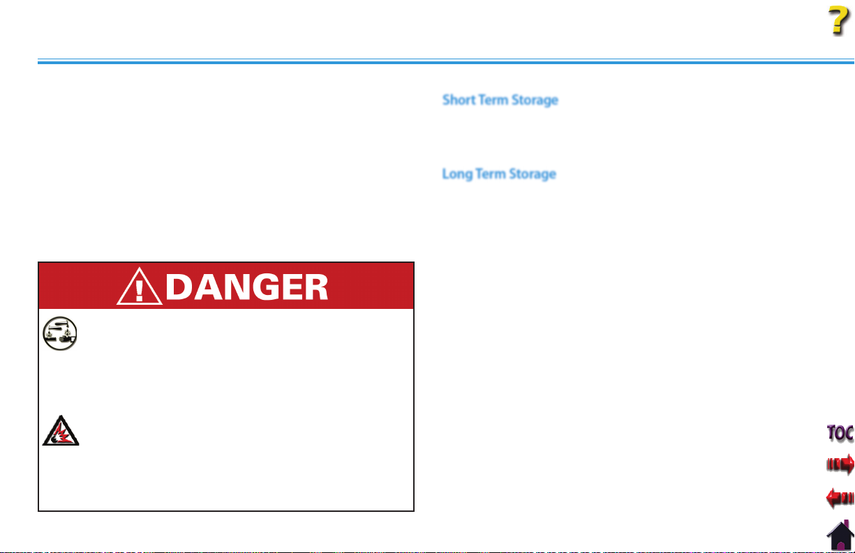
OPTION OPERATION
Intelect® Legend XT Therapy System
BATTERY MODULE SERVICE LIFE
Since NiMH Batteries are designed for multiple cycles of charging
and discharging, the expected cycle life of the Battery Module is
at minimum 500 cycles utilizing proper discharging and charging
procedures.
When the service time (use time between charges) of the
Battery Module is significantly reduced, the service life of the
Battery Module is exceeded and should be replaced with a new
Chattanooga Group Battery Module.
Never attempt to rebuild the Battery Module.
Properly dispose of old Battery Module.
•
NiMH Batteries contain Class E Corrosive materials. In the
event of battery cell rupture or leakage, handle Battery
Module wearing neoprene or natural rubber gloves. Contents
of a ruptured or leaking battery can cause respiratory
irritation. Hypersensitivity to nickel can cause allergic
pulmonary asthma. Contents of cell coming in contact with
skin can cause skin irritation and/or chemical burns.
•
Never, under any circumstances, open the Battery Module
housing or cells. Should an individual cell from a battery
become disassembled, spontaneous combustion of the
negative electrode is possible. There can be a delay between
exposure to air and spontaneous combustion.
Dispose of NiMH batteries according to national, state and
•
local codes and regulations.
STORING THE BATTERY MODULE
Short Term Storage
The Battery Module should be operated, transported and stored
in temperatures between 59° F and 104° F (15° C and 40° C), with
Relative Humidity ranging from 30%-60%.
Long Term Storage
For long term storage of the Battery Module, remove the Battery
Module from the System and store in temperatures between
59° F and 104° F (15° C and 40° C), with Relative Humidity ranging
from 30%-60%.
When charging the Battery Module for the first time after long
term storage, restore the battery service life by charging and
discharging the Battery Module several times.
If storing the Battery Module for periods longer than one
year, charge the Battery Module at least once per year to
prevent performance deterioration and battery leakage due to
self-discharge from storage.
85
Page 92
TROUBLESHOOTING
Intelect® Legend XT Therapy System
ERROR CODES
General Information
The Intelect Legend XT Therapy Systems incorporate error messages, and warnings to inform the user of problems or potential problems
with the system, modality, or accessories. These are numbered so the user can possibly correct the problem without the aid of service
personnel. Use the following Troubleshooting Charts to define the error codes, and locate the probable cause and possible remedies
before contacting the dealer or factory for technical service.
Code
Number
100 Warning Overcurrent A. Check Electrodes and Lead Wires. Make certain Lead Wires are not damaged and are
101 Warning Shorted Lead Wires A. Check Electrodes and Lead Wires. Make certain Lead Wires are not damaged and are properly
102 Warning Bad Contact Quality A. Make certain Electrodes are making proper contact with the treatment area.
103 Warning Blank Patient ID Properly enter Patient ID. Refer to Therapy System User Manual for Patient Data Card instructions.
104 Warning 1. Blank Protocol Name
106
107
Type
Message
Warning
Warning
Probable Cause Possible Remedies
2. Blank Sequence Name
1. Attempting to delete factory set Sequence.
2. Attempting to delete Clinical Protocol.
properly connected to the system. Make certain Lead Wires are properly connected to
the Electrodes and that electrodes are not damaged and are making proper contact with
treatment area.
B. Replace Lead Wires and Electrodes.
connected to the system. Make certain Lead Wires are properly connected to the Electrodes
and that electrodes are not damaged and are making proper contact with treatment area.
B. Replace Lead Wires and Electrodes.
B. Make certain Lead Wires are properly connected to Electrodes.
C. Replace Electrodes and Lead Wires.
Properly enter Protocol or Sequence Name. Refer to the appropriate section of the Therapy System
User Manual.
Cannot delete factory set Clinical Protocols or factory set Sequences.
86
Page 93

TROUBLESHOOTING
ERROR CODES (continued)
Intelect® Legend XT Therapy System
Code
Number
108 Warning Attempting to save additional User Protocols or Sequences after
109
110
111
112 Warning Ultrasound Applicator disconnected from system during treatment
113 Warning Attempting to perform Ultrasound treatment with no Applicator
114 Warning Ultrasound Applicator is not calibrated. Attempt to use a known good Applicator. If problem continues, contact dealer or Chattanooga
115 Warning Ultrasound Applicator is too hot. Allow Ultrasound Applicator Sound Head to cool to ambient temperature.
116
117
Type
Message
Warning
Warning
Warning
Warning
Warning
Probable Cause Possible Remedies
system memory has reached the maximum allowed (200).
Attempting to access protocols and none are found in the system. A. User Protocols- No protocols have been saved in the system. Refer to Therapy System User
session.
connected to the system.
1. No Patient Data Card is inserted into the system.
2. Attempted to use an Invalid Patient Data Card.
Delete some User Protocols or Sequences. Refer to appropriate section of the Therapy System User
Manual for instructions.
Manual to save User Protocols.
A. Connect Ultrasound Applicator to system.
B. If Ultrasound Applicator is connected, reset system by turning power switch Off and On.
C. If problem persists, connect a known good Ultrasound Applicator. If problem continues,
contact dealer or Chattanooga Group for service.
A. Connect the desired Ultrasound Applicator to the system.
B. If Ultrasound Applicator is connected, reset system by turning power switch Off and On.
C. If problem persists, connect a known good Ultrasound Applicator. If problem continues,
contact dealer or Chattanooga Group for service.
Group for service.
A. Properly insert the Patient Data Card into the system port. Refer to Therapy System User
Manual for new and existing Patient Data Card instructions.
B. Attempt to use a known good Patient Data Card.
C. Make certain only a Patient Data Card is being used.
D. If problem continues, contact dealer or Chattanooga Group for service.
87
Page 94
TROUBLESHOOTING
ERROR CODES (continued)
Intelect® Legend XT Therapy System
Code
Number
118 Warning Attempting to save additional User Protocols after system memory
119
120
121
122
123 Warning Patient Data Card is full. Erase Patient Data Card. Refer to Therapy System User Manual for instructions.
124 Warning Patient Treatment Data already saved. A. Cannot save same data again on Patient Data Card.
126 Warning No valid channels are available for attempted treatment. A. Complete existing treatment before attempting to start another.
135 Warning Control Board Software upgrade warning. Upgrade Control Board Software to latest version. Contact dealer or Chattanooga Group for latest
136 Warning Stim Board Main Software upgrade warning. Upgrade Stim Board Software to latest version. Contact dealer or Chattanooga Group for latest
137 Warning Stim Board Main Software upgrade warning. Upgrade Stim Board Software to latest version. Contact dealer or Chattanooga Group for latest
Type
Message
Warning
Warning
Warning
Warning
Probable Cause Possible Remedies
has reached the maximum allowed (200).
1. Attempted to read a treatment from Patient Data Card that is
not a valid treatment for the system
2. Attempted to use a Non-Patient Data Card.
3. No Patient Data Card inserted into system port.
4. Unknown type of smart card inserted into system.
Delete some User Protocols. Refer to appropriate section of the Therapy System User Manual for
instructions.
A. Use a Patient Data Card with proper treatment data for the system.
B. Properly insert a Patient Data Card.
C. Insert a known good Patient Data Card.
D. If problem continues, contact dealer or Chattanooga Group for service.
B. Use a new Patient Data Card to resave data.
C. Erase Patient Data Card and resave treatment data.
B. Reset Therapy System by turning main power switch Off and On.
software upgrade and instructions.
software upgrade and instructions.
software upgrade and instructions.
88
Page 95

TROUBLESHOOTING
ERROR CODES (continued)
Intelect® Legend XT Therapy System
Code
Number
138 Warning Ultrasound Board Software upgrade warning. Upgrade Ultrasound Board Software to latest version. Contact dealer or Chattanooga Group for
141 Warning Battery Module Software upgrade warning. Upgrade Battery Software to latest version. Contact dealer or Chattanooga Group for latest
145 Warning Patient Data Card button on Home screen was pressed with no
Type
Message
Probable Cause Possible Remedies
Patient Data Card installed into system port and no treatment
currently being performed.
In the event that an Error message or Warning appears beginning
with a 2 or 3, immediately stop all use of the system and contact the
dealer or Chattanooga Group for service. Errors and Warnings in these
categories indicate an internal problem with the system that must be
tested by Chattanooga Group or a Field Service Technician certified by
Chattanooga Group before any further operation or use of the system
Use of a system that indicates an Error or Warning in these categories
may pose a risk of injury to the patient, user, or extensive internal
damage to the system.
latest software upgrade and instructions.
software upgrade and instructions.
Properly insert a Patient Data Card, set up and perform the treatment and save data to Patient
Data Card.
89
Page 96

REPLACEMENT ACCESSORIES
Intelect® Legend XT Therapy System
GENERAL INFORMATION
The following provides the users of the Intelect Legend XT Therapy System the necessary information to order the replacement accessories
most commonly used with the System. This list of replacement accessories are designed for use with the Intelect Legend XT Therapy
System. When ordering, provide the respective part number, description and quantity desired.
PART NUMBER DESCRIPTION
2767 Battery Module
2781 Channel 3/4 Electrotherapy Module
2775 Therapy System Cart
2768 Patient Data Management System
27465 Patient Data Card (Pack of 25)
27469 Patient Interrupt Switch (Channel 1 & 2)
27470 Patient Interrupt Switch (Channel 3 & 4)
27312 Electrotherapy Lead Wire- Channel 1
27313 Electrotherapy Lead Wire- Channel 2
27314 Electrotherapy Lead Wire- Channel 3
27315 Electrotherapy Lead Wire- Channel 4
PART NUMBER DESCRIPTION
27508 Operator Remote- Channels 1 & 2
27079 Operator Remote- Channels 3 & 4
2
27333 1 cm
27334 2 cm
27335 5 cm
27336 10 cm
27468 Carrying Bag
79977 High Voltage Pulsed Current (HVPC) Probe Kit
79976 Microcurrent Probe Kit
1264 Nylatex® Wrap- 3 pack, 2.5 in X 24 in (6 cm X 61 cm)
72852 Black Rubber Carbon Electrodes- 3 in (8 cm) Round
72853 Red Rubber Carbon Electrodes- 3 in (8 cm) Round
42044 DURA-STICK™ II 2.75 in (7 cm) Electrodes (40/case)
4248 Conductor™ Ultrasound Gel- 9 oz Bottle (24/case)
Ultrasound Applicator
2
Ultrasound Applicator
2
Ultrasound Applicator (Standard)
2
Ultrasound Applicator
90
Page 97

MAINTENANCE
CARING FOR THE THERAPY SYSTEM FACTORY SERVICE
Cleaning the Therapy System
With the system disconnected from the power source, clean the
system with a clean, lint free cloth moistened with water and
mild antibacterial soap. If a more sterile cleaning is needed, use a
cloth moistened with an antimicrobial cleaner.
Do not submerse the system in liquids. Should the unit
accidentally become submersed, contact the dealer or
Chattanooga Group Service Department immediately. Do not
attempt to use a system that has been wet inside until inspected
and tested by a
Do not allow liquids to enter the ventilation holes in the optional
modules. This could permanently damage the modules.
Cleaning the Lens
Clean the Therapy System Screen Lens using NOVUS® Polish System.
Contact Novus at: www.novuspolish.com
CALIBRATION REQUIREMENTS
Calibrating Ultrasound Applicators
Annual factory calibration is required for all Ultrasound Applicators.
Only the Applicators should be sent to the factory or a Field
Technician certified by Chattanooga Group for this procedure.
NOVUS is the Registered Trademark of NOVUS Inc.
Service Technician Certified by Chattanooga Group.
When the
accessory modules require factory service, contact the selling dealer
or Chattanooga Group Service Department.
All Therapy System and accessory modules returned to the factory for
service must include the following:
WARRANTY REPAIR/OUT OF WARRANTY REPAIR
1. Written statement containing the following information:
•
•
•
•
•
•
•
2. Copy of original invoice issued at purchase of the Therapy System
or Module.
3. Ship the unit to address specified by an authorized service
technician.
Service to these units should be performed only by Service
Technicians certified by Chattanooga Group.
Ultrasound Applicators require annual calibration, from the date
placed in service, by the Factory or a Service Technician certified by
Chattanooga Group.
Intelect Legend XT Therapy System
RA Number- Obtain from Factory
Therapy System or Module Model Number
Therapy System or Module Serial Number
Contact Person with Phone and Fax Numbers
Billing Address (for Out of Warranty Repair)
Shipping Address (Where to Ship Unit after Repair)
Detailed Description of Problem or Symptoms
Intelect® Legend XT Therapy System
or any of the
91
Page 98

WARRANTY
Chattanooga Group ("Company") warrants that the Intelect Legend XT Therapy System and Channel 3/4 Electrotherapy Module ("Products") are free of defects in material and workmanship. This
warranty shall remain in effect for two years (24 months) from the date of original consumer purchase. If these Products fail to function during the two year warranty period due to a defect in
material or workmanship, Company or the selling dealer will repair or replace the respective Product without charge within a period of thirty (30) days from the date on which the Product is returned
to the Company or the dealer.
All repairs to the Product must be performed by a service center authorized by the Company. Any modifications or repairs performed by unauthorized centers or groups will void this warranty.
The warranty period for certain accessories is 90 days. Accessories consist of Lead Wires, Operator Remote, Electrodes, Patient Data Cards, and Nylatex®.
The warranty period for the Therapy System Cart, Battery Module and Ultrasound Applicators is one year (12 Months).
To participate in warranty coverage, this Product's warranty registration card (included with Product) must be filled out and returned to the Company by the original owner within ten (10) business
days of purchase.
This Warranty Does Not Cover:
• Replacement parts or labor furnished by anyone other than the Company, the selling dealer or a certified Company service technician.
• Defects or damage caused by labor furnished by someone other than Company, the selling dealer or a certified Company service technician.
• Any malfunction or failure in the Product caused by product misuse, including, but not limited to, the failure to provide reasonable and required maintenance or any use that is inconsistent
with the Product User's Manual.
COMPANY SHALL NOT BE LIABLE IN ANY EVENT FOR INCIDENTAL OR CONSEQUENTIAL DAMAGES.
Some states do not allow the exclusion or limitation of incidental or consequential damages, so the above limitation or exclusion may not apply to you.
To Obtain Service From Company or the selling dealer under this warranty:
1. A written claim must be made within the warranty period to the Company or the selling dealer. Written claims made to the Company should be sent to:
4717 Adams Road
P.O. Box 489
Hixson, TN 37343 USA
Telephone: 1-423-870-2281 or 1-800-592-7329 U.S.A.
1-800-366-6661 CANADA
+1-423-870-7200 Outside USA
1-423-875-5497 Facsimile
and
2. The Product must be returned to the Company or the selling dealer by the owner.
This warranty gives you specific legal rights and you may also have other rights which vary from location to location.
The Company does not authorize any person or representative to create for it any other obligation or liability in connection with the sale of the Product.
Any representative or agreement not contained in the warranty shall be void and of no effect.
THE FOREGOING WARRANTY IS IN LIEU OF ALL OTHER WARRANTIES, EXPRESSED OR IMPLIED, INCLUDING ANY WARRANTY OR MERCHANTABILITY OR FITNESS FOR A PARTICULAR PURPOSE.
Intelect® Legend XT Therapy System
92
Page 99

ISO 13485 CERTIFIED
4717 Adams Road
P.O. Box 489
Hixson, TN 37343
Telephone:
1-423-870-2281
1-800-592-7329 U.S.A.
U.S.A.
U.S.A.
1-800-366-6661 CANADA
+1-423-870-7200 OUTSIDE U.S.A
+1 423-870-2046 OUTSIDE U.S.A. FAX
chattgroup.com
27423D
© 2006 Encore Medical, L.P.
0413
 Loading...