

Page 1
Operating Manual
Chattanooga Intelect F-SW
29097.0002
TT.####
Part No. 26933.0012
Published: October 2018
Original language: German
Publisher:
STORZ MEDICAL AG
Lohstampfestr. 8
CH-8274 Tägerwilen
Switzerland
Focus Shockwave
Operating Manual
Page 2

Table of Contents
1 General Safety Information 7
1.1 Instructions for safe use 7
1.1.1 Intended use and operational safety . . . . . . . . . . . . . 7
1.1.2 Safety during treatment of the patient. . . . . . . . . . . . . 9
1.2 Warning against damage to equipment and the device 9
1.3 Manufacturer‘s responsibility 11
1.4 Owner‘s responsibility 11
2 Principles 12
2.1 Physical principles 12
2.1.1 Indications . . . . . . . . . . . . . . . . . . . . . 12
2.1.2 Contraindications . . . . . . . . . . . . . . . . . . . 14
2.1.3 Side effects . . . . . . . . . . . . . . . . . . . . . 14
2.2 Preconditions for operation 15
2.2.1 Operating personnel . . . . . . . . . . . . . . . . . . 15
2.2.2 Training of the operator . . . . . . . . . . . . . . . . . 15
2
3 System Description 16
3.1 Control and functional elements 16
3.2 F-SW handpiece and optional C-ACTOR handpiece 17
3.3 Use of stand-off devices 18
4 Installation Instruction 20
4.1 Scope of supply 20
4.2 Unpacking 20
4.3 Correct positioning of the device 20
4.4 Handpiece holder installation 21
4.4.1 Installing the F-SW holding arm (optionally) . . . . . . . . . . . 21
4.4.2 Connecting power supply cables . . . . . . . . . . . . . . 22
4.4.3 Handpiece connection . . . . . . . . . . . . . . . . . 22
4.4.4 Connecting the optional foot switch . . . . . . . . . . . . . 23
4.4.5 Potential equalisation (optional). . . . . . . . . . . . . . . 23
4.4.6 USB connection . . . . . . . . . . . . . . . . . . . 23
4.5 Transport 24
4.6 Compatibility 24
Table of Contents
13 610 02 1018
Page 3

5 Operation 25
5.1 User interface 25
5.2 Overview of menu functions 29
5.3 Starting the instrument 32
5.4 Setting the treatment parameters 34
5.5 F-SW Energy display task 36
5.6 Storing the treatment parameters 37
5.7 Loading treatment parameters 39
5.7.1 Pre-programmed indications from the manufacturer . . . . . . . . 39
5.7.2 In-house applications . . . . . . . . . . . . . . . . . . 41
5.8 Patient record 42
5.9 Visual analogue scale (VAS) 44
5.10 Data transfer 45
5.11 Software updates 48
5.11.1 Loading the software onto the USB stick . . . . . . . . . . . . 48
5.11.1.1 Extracting the software using Windows . . . . . . . . . . . . 48
5.11.2 Extracting the software with WinZip . . . . . . . . . . . . . 49
5.11.3 Updating the software on the instrument . . . . . . . . . . . . 50
5.12 Resetting the treatment shock counter 50
5.13 “Autofrequency” function 51
5.14 Start-up 52
5.15 Functional checks 54
5.16 Standard settings 54
5.17 Treatment 55
5.18 Switching off the device 55
6 Cleaning, Maintenance and Overhaul 56
6.1 Cleaning the device 56
6.2 Cleaning the handpiece 57
6.2.1 Changing the stand-off device . . . . . . . . . . . . . . . 57
6.2.2 Reprocessing of the handpiece and the stand-off devices . . . . . . . 58
6.2.2.1 Cleaning. . . . . . . . . . . . . . . . . . . . . . 58
6.2.2.2 Disinfection . . . . . . . . . . . . . . . . . . . . . 58
6.3 Cleaning the optional foot switch 59
3
6.4 Water renewal 60
6.4.1 Draining the water circuit . . . . . . . . . . . . . . . . 60
13 610 02 1018
Table of Contents
Page 4

6.4.2 Filling the water circuit . . . . . . . . . . . . . . . . . 62
6.4.3 Bleeding the water circuit . . . . . . . . . . . . . . . . 64
6.4.4 Resetting the water renewal time . . . . . . . . . . . . . . 64
6.5 Fuse replacement 65
6.6 Maintenance and safety checks 65
6.7 Disposal 66
6.8 Repair 66
6.9 Service life 66
7 Status messages and trouble-shooting 67
7.1 Status messages 67
7.2 Trouble-shooting 69
8 Accessories 70
9 TechnicalSpecications 71
9.1 TechnicalSpecications 71
9.2 Type plate Chattanooga Intelect F-SW 75
9.3 Conformity with directives 75
4
9.4 Conformity with standards 75
9.5 Certicates 80
9.6 Symbols and labels 81
10 Warranty and Service 84
10.1 Warranty for the control device 84
10.2 Warranty for the F-SW handpiece and the C-ACTOR Handpiece 85
10.3 Service 85
Table of Contents
13 610 02 1018
Page 5
Preface
Warning notes
This manual contains warnings, safety instructions and specic operating instructions
in accordance with liability regulations.
DANGER refers to a situation of acute danger which, if not avoided, could lead to
serious or fatal injury.
DANGER!
The source of the danger is stated here.
These are the possible consequences!
• The instructions for avoiding the danger are given here.
WARNING refers to a situation of potential danger which, if not avoided, could lead
to serious injury.
WARNING!
The source of the danger is stated here.
These are the possible consequences!
• The instructions for avoiding the danger are given here.
CAUTION indicates that incorrect operation could lead to minor injuries.
CAUTION!
The source of the danger is stated here.
These are the possible consequences!
• The instructions for avoiding the danger are given here.
ATTENTION indicates that incorrect operation could lead to damage to the device.
ATTENTION!
The source of the danger is stated here.
These are the possible consequences!
• The instructions for avoiding the danger are given here.
5
13 610 02 1018
Other instructions
NOTE
Additional information concerning specic features or operating instructions is
preceded by the term 'NOTE'.
Preface
Page 6
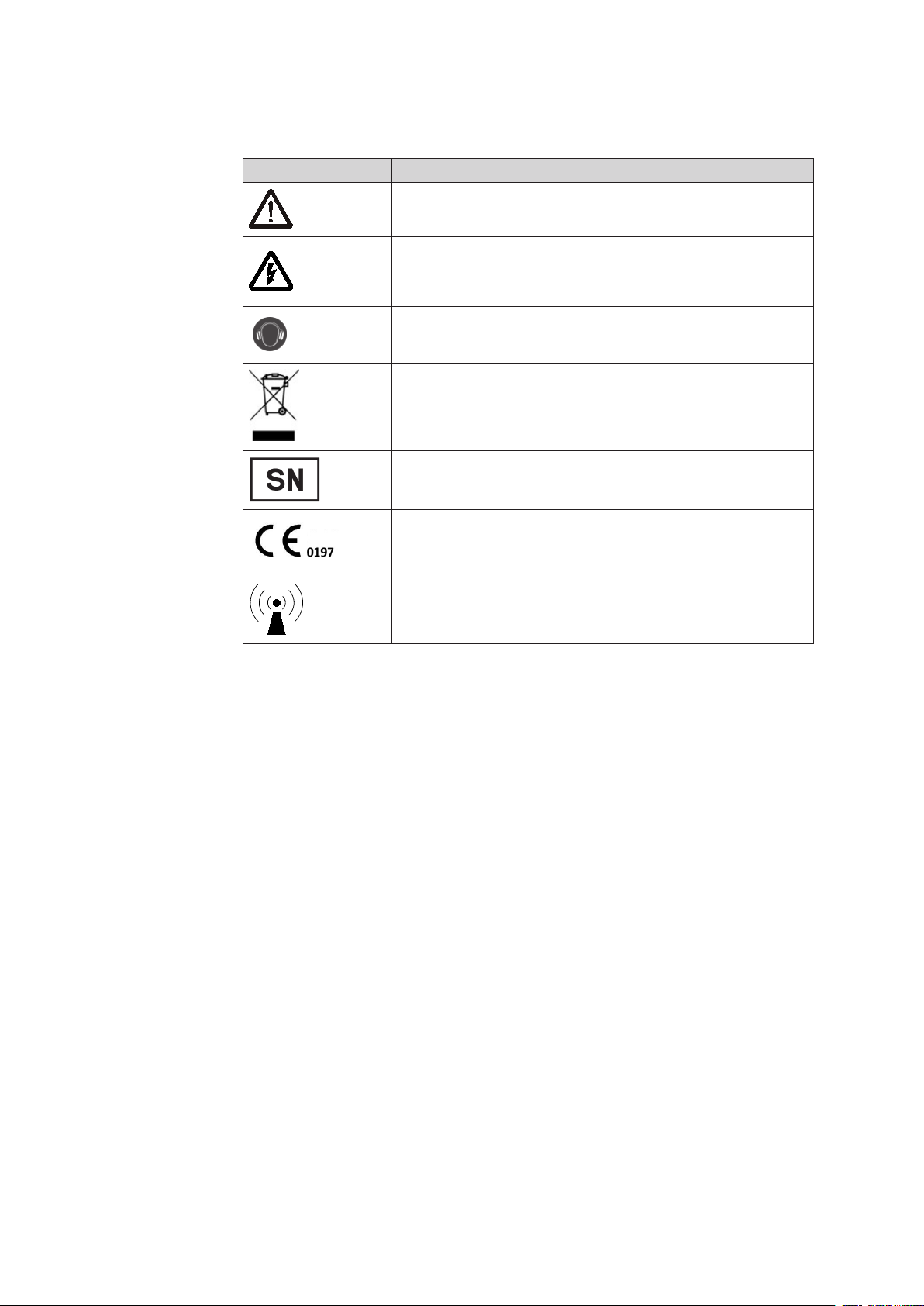
Safety signs and other symbols used in this manual
Symbol Name
General warning sign
Electrical warning sign
Table 1-1
Wear hearing protection!
WEEE (waste electrical and electronic equipment)
Device serial number
CE mark
Electromagnetic interference may occur in the vicinity of
instruments marked with this symbol.
6
Preface
13 610 02 1018
Page 7

1 General Safety Information
1.1 Instructions for safe use
The following chapter contains all safety information that has to be followed when
working with the Chattanooga Intelect F-SW.
WARNING!
Incorrect handling of the device.
Possibility of injuries to the patient and the operating personnel!
• Read this chapter carefully before you start using the Chattanooga
Intelect F-SW.
• Read the separate operating manuals for all devices associated
with the Chattanooga Intelect F-SW.
1.1.1 Intended use and operational safety
To use this device in accordance with its intended use, the user must possess the
necessary technical prociency, and knowledge of the operating manual.
The Chattanooga Intelect F-SW is intended exclusively for use by healthcare
professionals who have been trained to use the device (see also chapter 2.2
precOnditiOns fOr OperatiOn).
The device is only allowed to be used for the applications described in chapter 2.1.1
indicatiOns.
Only perform treatments approved by the manufacturer!
Furthermore, the device is only allowed to be operated by trained personnel who
comply with the precOnditiOns fOr OperatiOn in chapter 2.2.
All status and error messages signaled during treatment must always be attended to
without delay.
While applying focused shockwaves at maximum adjustment, do not use more than
6.000 subsequent shocks and stick to a consecutive break of 5 minutes.
Checks and inspections prior to treatment
Before using the device, the user must make sure it is functioning safely and that it is
in proper condition.
• It is essential to perform the functional checks after switching on the Chattanooga
Intelect F-SW before starting treatment. Read about this in chapter 5.15 functiO-
nal checks.
7
13 610 02 1018
• Have the maintenance procedures recommended by the manufacturer carried out by
authorised personnel (see also chapter 6.6 Maintenance and safety checks).
No treatment ist permitted if a display on the control device or a touch screen fails.
General Safety Information
Page 8

Protection against electrical hazard
Sources of voltage can give rise to currents as a result of body resistance which not
only ow through the patient but can also impair or even endanger the physician and
the nursing staff.
• Therefore, always connect the potential equalisation connector of the Chattanooga Intelect F-SW in accordance with national guidelines.
• Devices which are not medical products in accordance with EN 60601 must be set
up outside the vicinity of the patient.
• Do not touch electrical connectors while you are touching the patient.
• Disconnect the connected handpieces from the device before carrying out cleaning
and maintenance work. Do not reconnect them until they have been completely
reassembled!
• Do not try to open the instrument! Risk of electric shocks!
Protection against high voltage
Very high voltages are generated when operating the device.
High-voltage components are identied as follows:
8
Protection against noise
The noise level during administration of shock waves is within the safe area.
Nevertheless, we recommend wearing suitable ear protection during treatment in
order to minimise exposure to noise.
Protection against explosion
Do not use the Chattanooga Intelect F-SW in potentially explosive environments, i.e.
in the presence of a ammable anaesthetic mixture with air or with oxygen or nitrous
oxide.
The optional foot switch must not be used in potentially explosive atmospheres accor-
ding to classication AP as per IEC 60601.
DANGER!
Contact with high-voltage parts
Severe or fatal injury!
• Only operate the device if the housing is intact and closed.
• Work in the area of high voltage is only allowed to be performed
by personnel suitably authorised by the manufacturer.
General Safety Information
13 610 02 1018
Page 9

1.1.2 Safety during treatment of the patient
General note:
Organs with gas inclusions, in particular parts of the lung, are NOT allowed to be
exposed to shock waves.
As it passes through tissue, the shock wave’s energy is slightly reduced; this reduction
is signicantly weakened by the bone structure.
Shock waves can give rise to undesirable heart reactions. The patient must be
continuously observed during the treatment.
• While applying focused shockwaves at maximum adjustment, do not use more
than 6.000 subsequent shocks and stick to a consecutive break of 5 minutes.
• Only perform treatments approved by the manufacturer!
The user is responsible for correctly positioning the handpieces and correctly selecting
the treatment zone.
Air bubbles reduce the effectiveness of shock waves. Therefore, air bubbles must
always be removed from the shock wave path.
1.2 Warning against damage to equipment and the device
Any damage to the device resulting from incorrect operation is not covered by the
manufacturer’s warranty.
Electromagnetic compatibility
This device complies with the requirements of the applicable standard on
electromagnetic compatibility.
Nevertheless, portable and mobile HF communications equipment (e.g. mobile
phones) can interfere with medical electrical equipment.
This device is subjected to special precautions regarding EMC and needs to be
installed according the EMC guidelines in chapter 9.4 cOnfOrMity with standards.
The use of accessories or cables that are not authorised by the manufacturer can
result in increased interference emissions or reduced resistance to interference
emissions by the device.
The Chattanooga Intelect F-SW is not allowed to be positioned immediately next
to or jointly with other devices. If the operation near or jointly with other devices is
required, the Chattanooga Intelect F-SW must be tested in that particular environment
to ensure operation according to technical specication.
9
13 610 02 1018
If the Chattanooga Intelect F-SW is connected to a 240 V mains supply with a mains
frequency of 60 Hz, the mains supply must be balanced
The system must only be connected to properly earthed and correctly installed
shockproof sockets!
General Safety Information
Page 10

Set-up and operation
• Check that the installation surfaces have sufcient carrying capacity to avoid
equipment damage!
There are ventilation slits on the left side of the device which must not be covered by
other objects.
• Check that the system is in perfect working order before each use. Read about this in
chapter 5.15 functiOnal checks.
• Never cover the device when in use!
• Make absolutely sure that no liquid can seep into the system housing or
handpiece.
Storage and transport
Incorrect storage and transport can result in damage to the device and device failure.
• Make sure that no cables are crushed or sheared.
Disposal
• Comply with national disposal regulations when disposing of the Chattanooga
Intelect F-SW or individual components.
• Comply with the relevant information in the operating manuals for the additional
devices.
10
General Safety Information
13 610 02 1018
Page 11

1.3 Manufacturer‘s responsibility
WARNING!
No modications are to be made to this device without the permission
of the manufacturer.
STORZ MEDICAL AG as the manufacturer of the Chattanooga Intelect F-SW is only
responsible for effects on the safety, reliability and performance of its product if:
– Maintenance of the device is performed at the intervals specied by the manu-
facturer
– Installation, expansions, conversions, new installations, modications or repairs
are performed by people authorised by the manufacturer
– The electrical installation in the rooms in question corresponds to the require-
ments of DIN/IEC
– The device is used in compliance with the operating manual
The periodic maintenance measures specied by the manufacturer must be performed
on schedule by authorised personnel.
The manufacturer‘s liability shall be rendered null and void if non-genuine parts are
used.
1.4 Owner‘s responsibility
The owner is responsible for complying with the relevant national statutory provisions
governing setting up and operating technical medical equipment. (For Germany, the
Medical Products Act.)
It is expressly stated that the use of unauthorised accessories and/or unauthorised
equipment combinations shall render the product liability null and void.
The device is exclusively allowed to be used with accessories, wearing parts and disposable articles that have been checked by the testing body responsible for testing the
device to ensure that they function without risk.
11
13 610 02 1018
General Safety Information
Page 12

12
2 Principles
2.1 Physical principles
The Chattanooga Intelect F-SW is a universal, compact shock wave unit that can be
used for treatment involving medium- to high-energy electromagnetically generated
shock waves - focused shock waves – referred to below as F-SW.
F-SW waves have a short pulse length and are concentrated on areas a few
millimetres in diameter, allowing pulse waves to be applied to a tightly localised area,
even in deeper tissue layers.
2.1.1 Indications
The Chattanooga Intelect F-SW is designed in order to treat the indications specied
below:
Orthopaedics / Pain Therapy
– Plantar fasciitis / heel spur / heel pain / calcaneal spur
– Trigger Point Therapy
– Treatment of deep muscle trigger points
– Treatment of supercial muscle trigger points
– Myofascial pain syndrome / Myofascial trigger points* / Acupuncture points
– e.g. chronic back pain (cervical and lumbar parts of vertebral column), trape-
zius, pelvic oor muscle trigger points
– Tendinopathy / Tendinitis / Tendonitis / Tendinosis / Tendon Pain
– Insertion tendonitis in general
– Supercial insertion tendonitis (paratendinary area)
– Shoulder pain with or without calcications / tendinopathy of the shoulder,
the supraspinatus, or / and the rotator cuff (with or without calcications)
– (Radial/ulnar humeral) epicondylitis / tennis elbow / golfer’s elbow / elbow
tendinopathy
– Greater trochanteric pain syndrome (GTPS) / Trochanteric tendonitis / Tro-
chanteric bursitis
– Hamstring tendinopathy
– Patellar tip syndrome/ proximal iliotibial band (friction) syndrome / Patellar
tendonitis / Jumper’s knee
– Tibial edge syndrome / tibial stress syndrome / tibial tendonitis
– Achillodynia / Achilles tendinitis
Principles
– Pseudarthrosis / non-unions / delayed unions
13 610 02 1018
Page 13

Dermatology
– Wound healing
– Ulceration
– Arterial ulcers
– Venous ulcers
– Diabetic foot ulcers
– Pressure sore / Decubital ulcer
– Burns
– Acute and chronic lesions
– Traumatic and post-traumatic skin lesions
– Wounds with disturbed healing
– Postsurgical wounds
– Cellulitis / lipo- / lymphedema
Urology
– CPPS / prostatitis
– IPP / Peyronie’s disease
– Vascular / vasculogenic / organic erectile dysfunction
Neurology
– Spastic muscle paralyses (caused by infantile cerebral palsy or stroke for exam-
ple)
* A sound knowledge of trigger point therapy and trigger point shock wave therapy (TrST) is required for
therapeutic application of the Chattanooga Intelect F-SW in the eld of trigger point shock wave therapy.
13
13 610 02 1018
Principles
Page 14
2.1.2 Contraindications
CAUTION !
The contraindications listed here are examples. No claims are made
regarding the completeness or unlimited validity of this list of contraindications.
No patient treatment is allowed under the following circumstances:
– Air-lled tissue (in particular lung tissue) in the treatment area
– Brain or spine in the treatment area
– Untreated coagulopathies (hemophilia)
– Malignant tumor in the treatment area
– Epiphyseal plate areas in children
– Pregnancy
– Use of anticoagulants, especially Marcumar
– Thrombosis in the treatment area
– Cortisone therapy up to 6 weeks before rst treatment
14
CAUTION!
Shock waves must not be applied to target areas located above air
lled tissue (lungs), nor to any regions near large nerves, vessels,
the spinal column or head (apart from the face).
2.1.3 Side effects
– Swelling, reddening, hematoma
– Petechiae
– Pain
These side effects normally disappear after 5-10 days.
Principles
13 610 02 1018
Page 15

2.2 Preconditions for operation
2.2.1 Operating personnel
The Chattanooga Intelect F-SW is intended exclusively for use by healthcare
professionals who have been trained to use the device.
Such a specialist is expected to have practical knowledge of medical procedures and
applications as well as of the terminology, and should be experienced in treating the
indications stated in chapter 2.1.1 indicatiOns.
Users must have basic physical and cognitive abilities such as vision, hearing and
literacy, and have basic functional use of their upper extremities.
The device is designed for a demographic target group between 18 and 65 years.
2.2.2 Training of the operator
Operators of the Chattanooga Intelect F-SW must have been adequately trained in
using this system safely and efciently before they operate the device described in
this handbook. An introduction to the principles of operation will be provided by your
dealer with reference to this operating manual and will be documented in the system
logbook.
The operator must be instructed in the following points:
– Instruction in the operation and intended use of the device with practical exer-
cises
– Mechanism of action and function of the device and the energies delivered by
it
– All component settings
– Indications for use of the device
– Contraindications and side effects of the therapy waves
– Explanation of the warnings in all operating modes
– Instruction in how to perform the functional checks
Further training requirements vary from country to country. It is the operator’s responsibility to ensure that the training meets the requirements of all applicable local laws
and regulations. Further information about training in the operation of this system can
be obtained from your dealer. However, you can also contact the following address
directly:
DJO France
3 Rue de Bethar
Centre Européen de Frêt
64990 Mouguerre
France
T: +33 (0)5 57 52 86 90
F: +33 (0)5 57 52 86 91
E: sce.cial@DJOglobal.com
15
13 610 02 1018
Principles
Page 16
3 System Description
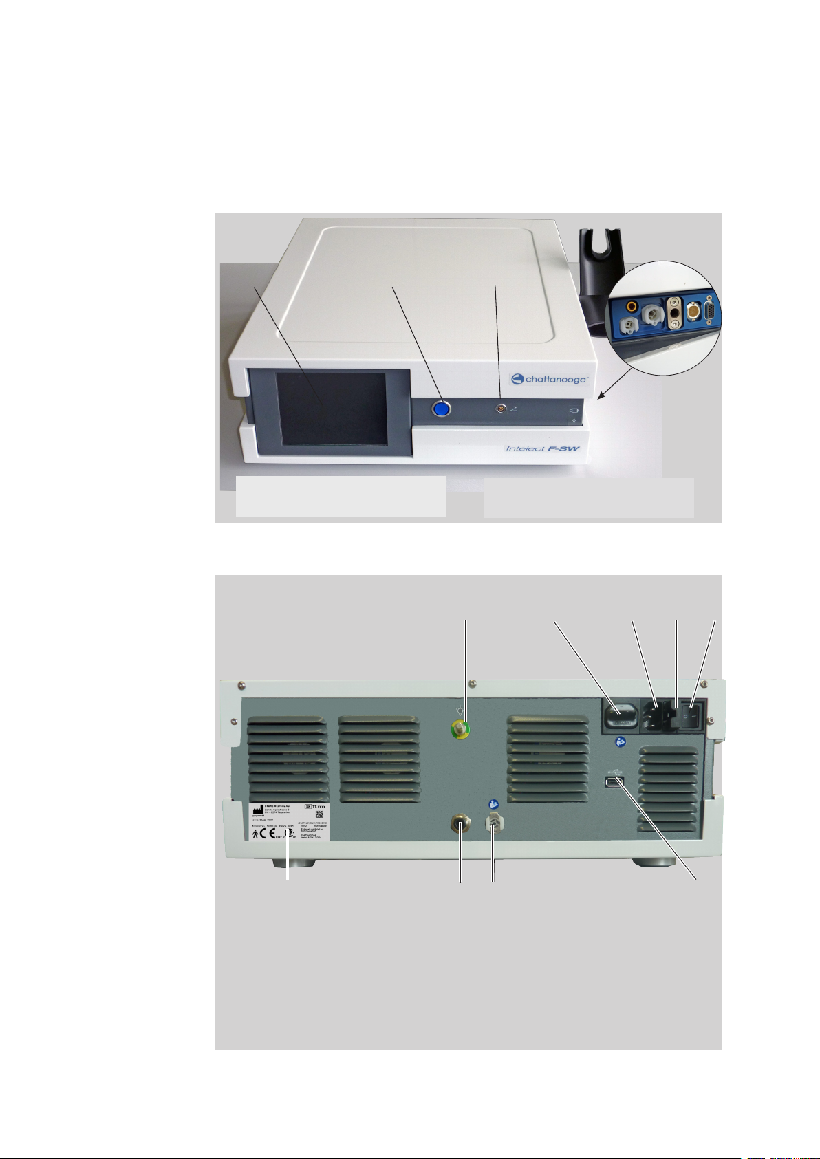
3.1 Control and functional elements
16
1
1 Monitor
2 Power indicator
Fig. 3-1 Front view of Chattanooga Intelect F-SW
2
3
3 Connection for foot switch
4 F-SW handpiece connection
1 2 3 4 5
4
Fig. 3-2 Rear view of Chattanooga Intelect F-SW
System Description
9
1 Potential equalisation connection
2 not used
3 Mains connection
4 Mains fuse holder
5 Mains switch
6 USB connection for USB stick, USB
mouse, USB keyboard
78
7 Water supply connection
8 not used
9 Type plate
6
13 610 02 1018
Page 17
NOTE
The following instruments can be connected to the USB connection:
– USB memory stick which supports the USB V1.1 protocol
– USB mouse
– USB keyboard
The connected instruments must be approved as medical products in accordance
with EN IEC 60601.
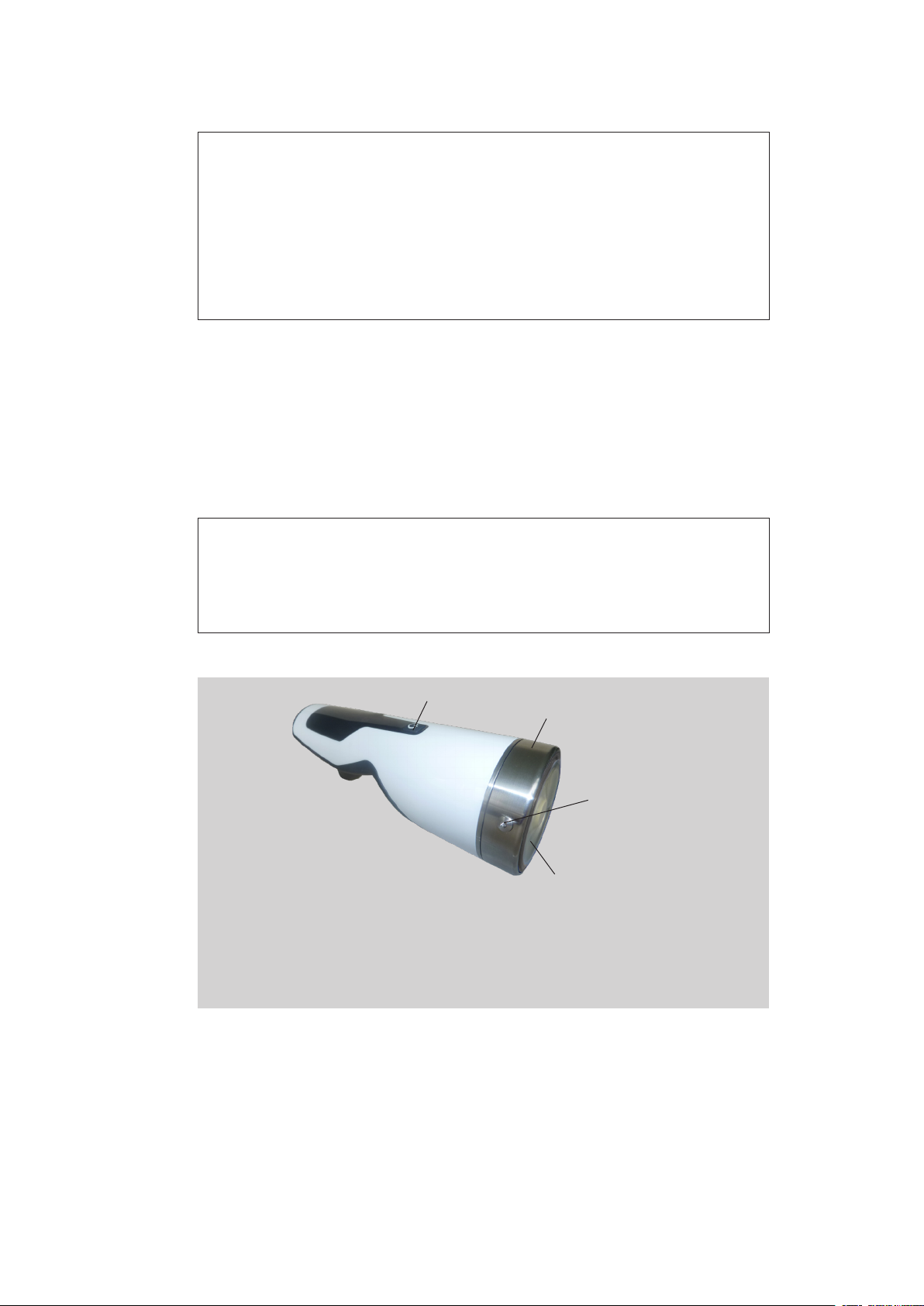
3.2 F-SW handpiece and optional C-ACTOR handpiece
Focused shock waves with a short wavelength that are concentrated on a focal zone
outside the handpiece are administered over the F-SW handpiece or the C-ACTOR
handpiece into the body at the treatment zone that has been established by diagnosis.
NOTE
Optical difference between F-SW handpiece and C-ACTOR handpiece:
The F-SW handpiece has a blue ring around the coupling diaphragm and the
C-ACTOR handpiece has a red ring around the coupling diaphragm.
1
2
3
4
1 Trigger button
2 Clamping ring
3 Fixing screws
4 Coupling diaphragm
Fig. 3-3 F-SW handpiece or C-ACTOR handpiece
The coupling diaphragm is xed by a clamping ring and 3 xing screws. It can only be
opened from authorised personnel with special tools.
The penetration depth of the shock wave can be varied by stand-off devices.
17
13 610 02 1018
System Description
Page 18

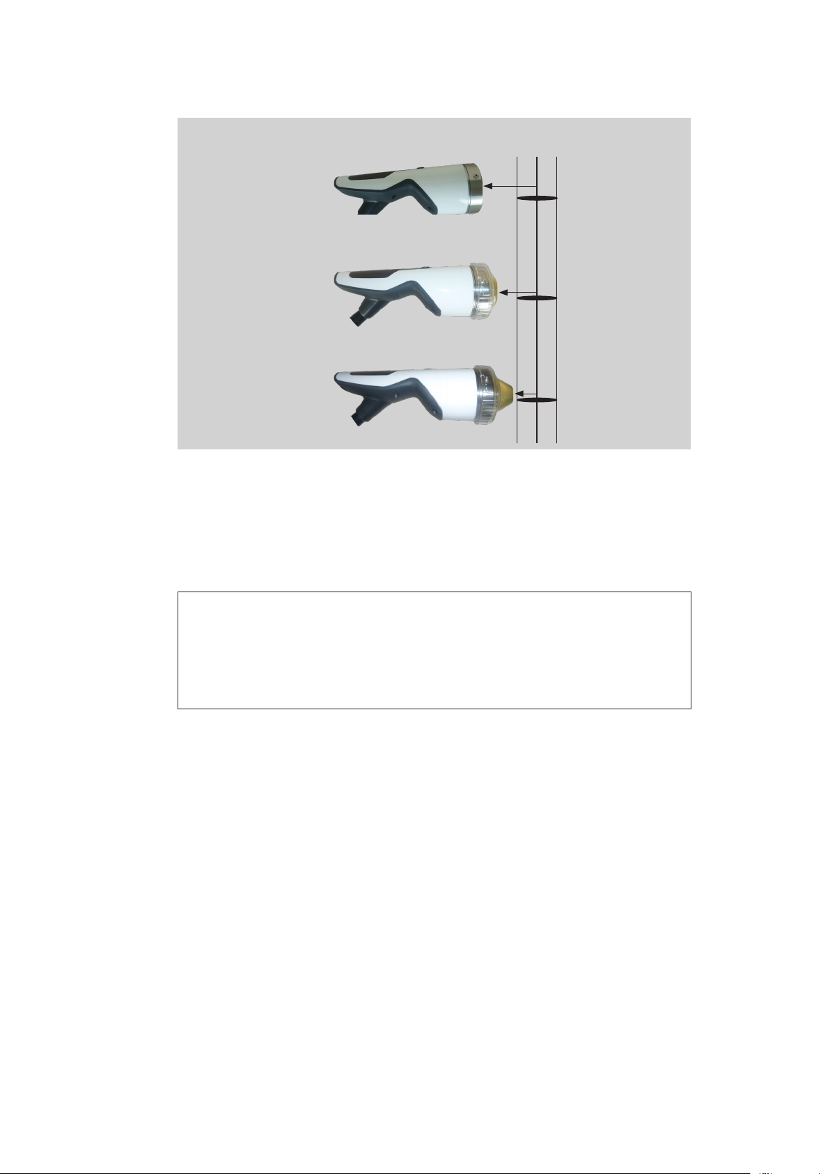
3.3 Use of stand-off devices
The penetration depth of the shock wave can be adjuted by using different stand-off
devices.
without stand-off device
with stand-off device I with stand-off device II
Fig. 3-4 F-SW handpiece or C-ACTOR handpiece
18
Therapeutically effective
penetration depth 5 MPa
50 mm
0 - 125 mm
0 - 105 mm
30 mm
15 mm
0 - 90 mm
Fig. 3-5 Depth of therapeutical effect of F-SW handpiece
Depth of
focal zone
35 - 65 mm
15 - 45 mm
0 - 30 mm
System Description
13 610 02 1018
Page 19
Therapeutically effective
penetration depth 5 MPa
0 - 65 mm
Depth of
focal zone
30 mm
20 - 40 mm
0 - 50 mm
15 mm
5 - 25 mm
0 mm
0 - 35 mm
0 - 10 mm
Fig. 3-6 Depth of therapeutical effect of C-ACTOR handpiece
• Perform changing of the stand-off devices as described in chapter 6.2.1 changing
the stand-Off device.
NOTE
The stand-off has a limited service life. It should be replaced if there are visible
changes in the material (discolouration, tarnishing, streaks, gas bubbles), deformation of the surface in the coupling area or leaks.
The stand-off should be replaced at least every 12 months.
19
13 610 02 1018
System Description
Page 20

4 Installation Instruction
4.1 Scope of supply
The standard scope of supply of the Chattanooga Intelect F-SW:
– Chattanooga Intelect F-SW
– F-SW SEPIA LT handpiece
– Handpiece holder
– Mains cables
– Gel bottle
– Silicone oil bottle
– Water bag
– User manual
4.2 Unpacking
20
• Carefully remove the instrument and accessories from the packaging container.
• Check that all items are included in the packaging container and that they are not
damaged.
• Contact your supplier or the manufacturer immediately if any items are missing or
damaged.
• Retain the original packaging. It may prove useful for any later equipment transport.
4.3 Correct positioning of the device
Make sure that the device is positioned at a distance from the wall so that the mains
plug can be pulled without restriction.
Installation Instruction
13 610 02 1018
Page 21

4.4 Handpiece holder installation
The handpiece holder can be mounted on the right as well as on the left side.
• Use a 2.5 mm Allen key for installation.
• Screw the handpiece holder onto the right side wall of the Chattanooga Intelect
F-SW, as shown in the picture below.
Fig. 4-7 Mounted handpiece holder
1
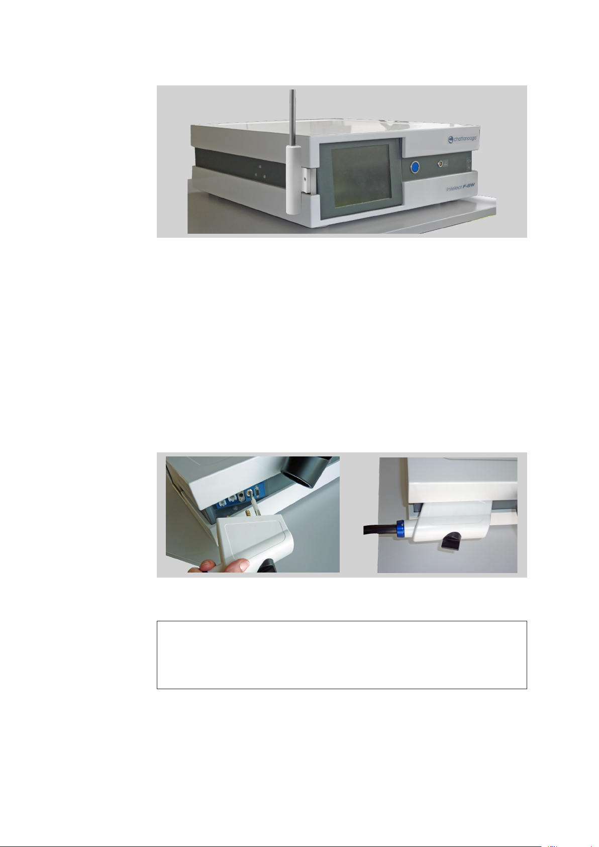
4.4.1 Installing the F-SW holding arm (optionally)
To facilitate handling of the F-SW handpiece, you can hook the F-SW
handpiece onto the optionally available holding arm.
• Use a 2.5 mm Allen key for installation.
• Screw the holder for the arm rmly onto the holes provided for it on the left of the
instrument (see picture below).
21
13 610 02 1018
Fig. 4-8 Attachment holes for the holding arm
• Place the holding arm into the holder.
Installation Instruction
Page 22
22
Fig. 4-9 Holding arm attached
4.4.2 Connecting power supply cables
• Connect the Chattanooga Intelect F-SW via the mains cable to the mains connector (Fig. 3-2/3).
4.4.3 Handpiece connection
• Connect the connector of the F-SW handpiece to the handpiece connection
provided on the Chattanooga Intelect F-SW and secure it using the black locking
screw. The locking screw must be tightened up to the stop until nger-tight.
Fig. 4-10 Connecting the F-SW handpiece
NOTE
Fill the water circuit of the Chattanooga Intelect F-SW rst when the F-SW handpiece is rst connected after delivery. The instrument will signal “water level too
low” when it is switched on.
Installation Instruction
13 610 02 1018
Page 23
4.4.4 Connecting the optional foot switch
• Connect the connection cable of the foot switch to the appropriate connection
on the front side of the instrument.
NOTE
The foot switch is protected against ingress of water according to classication
IPX8 as per IEC 60529.
4.4.5 Potential equalisation (optional)
The Chattanooga Intelect F-SW features a potential equalisation connection.
• Connect one end of the potential equalisation cable to the PE connection on the
Chattanooga Intelect F-SW and the other end to your PE connection.
CAUTION!
The potential equalisation connection on the Chattanooga Intelect
F-SW must be connected in accordance with the relevant national
regulations.
4.4.6 USB connection
The USB connection acts as an interface for data input and output.
• Connect if required
– a USB memory stick which supports the USB V1.1 protocol
– a USB mouse
– a USB keyboard
The connected instruments must be approved as medical products in accordance with
IEC 60601.
23
13 610 02 1018
Installation Instruction
Page 24

4.5 Transport
NOTE
Make sure that your hands are dry and free of grease.
ATTENTION !
The side walls of the device can be bent if it is not transported correctly.
Defect of the touchscreen or other components!
• DO NOT carry the device by means of mounted accessory parts (e.g. F-SW
plug).
• Dismount the handpiece holder before transporting the device.
• To transport the instrument, grip the indentations on the side of the housing as
shown in the picture below (1) and lift it carefully.
24
1
Fig. 4-11 Transporting the device
• Set the device slantly down in order to avoid squeezing the ngers.
4.6 Compatibility
The Chattanooga Intelect F-SW is allowed to be operated with the following accessories:
– Handpiece F-SW SEPIA LT Art. no. 19000
– Handpiece C-ACTOR SEPIA LT Art. no. 29204.0001
– Foot switch
Installation Instruction
13 610 02 1018
Page 25
5 Operation
The Chattanooga Intelect F-SW is operated using a colour TFT LCD monitor with
touch screen function and a graphical user interface.
5.1 User interface
The user interface of the Chattanooga Intelect F-SW is divided into various areas for
displaying different information. The individual controls are arranged in function
groups (see picture below):
1
Control buttons
9
2
Control buttons
3
4
5
Control buttons
8
7
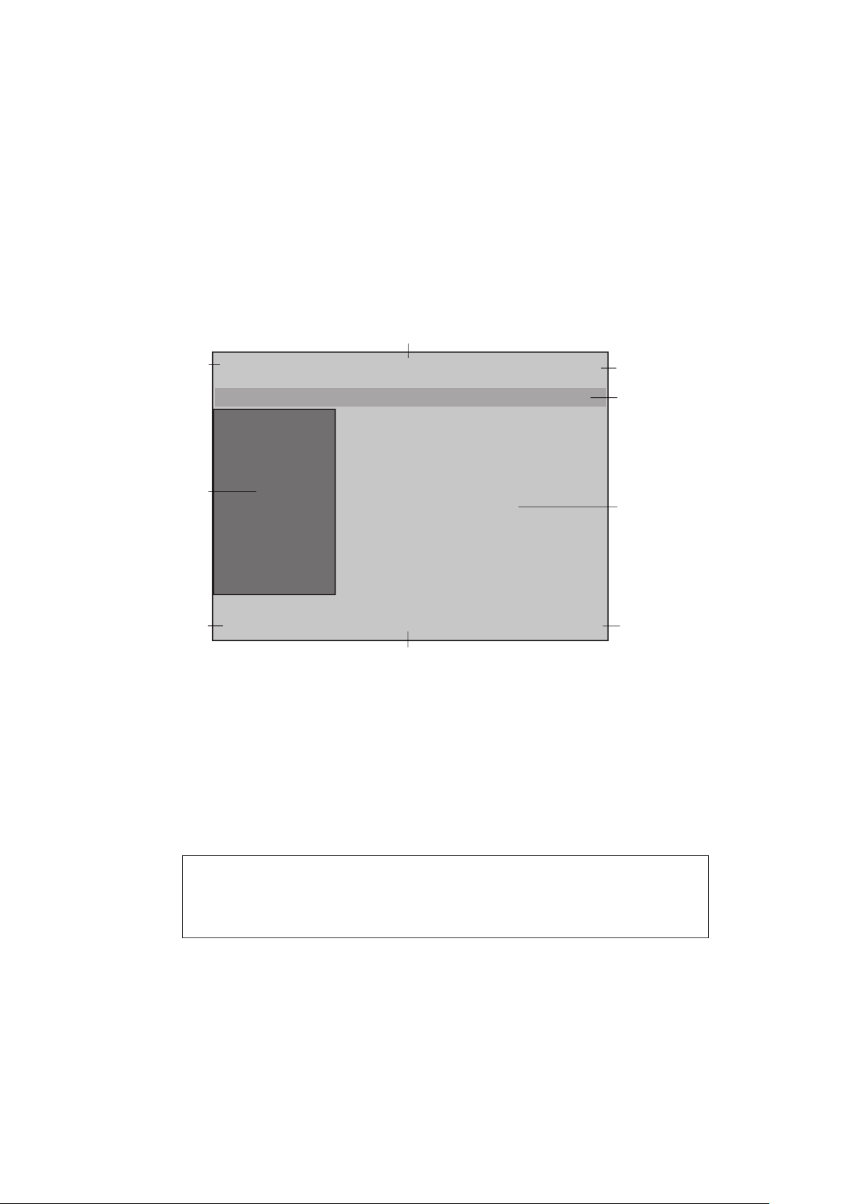
Fig. 5-12 Controls
1 - 3 Top navigation bar
4 Status bar
5 Selection area
6 - 8 Bottom navigation bar
9 Parameter display (nominal and actual values)
NOTE
The following functional description refers to control software version
13441.19.x.x or later (this can be seen in the Info menu).
Control buttons
6
25
13 610 02 1018
Operation
Page 26
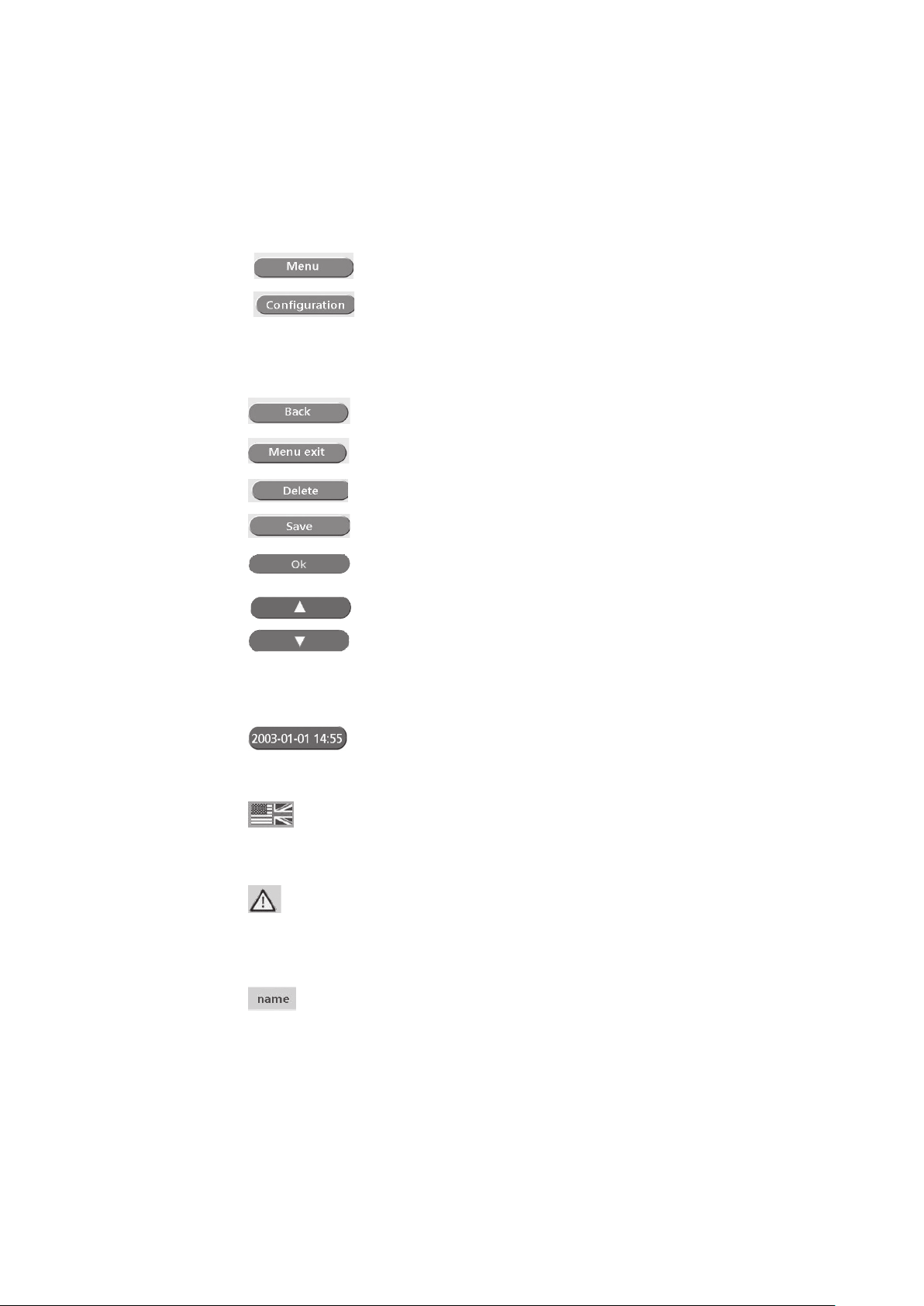
Navigation bars:
The top and bottom navigation bars (Fig. 5-12/1 to Fig. 5-12/3 and 3, Fig. 5-12/6
to Fig. 5-12/8) contain control buttons that you can use for navigating through
the menus:
Parameter entry screen:
Open the sub-menu
Jump to the “Load conguration” sub-menu (call
up saved parameter congurations or patient
records)
Main and sub-menu:
Step back
Return to parameter entry screen
Delete congurations
Save congurations
Conrm entries, acknowledge messages
26
The arrow keys can be used for changing (increasing
or decreasing) the parameter values.
If you are in a sub-menu that contains more menu
items than can be displayed in the top part of the
display, you can use the arrow keys to scroll to the
bottom of the list (page up/down).
Press the date key on the parameter input page to
open the “Info” window.
Status bar:
The ag on the right of the status bar displays the
menu language. Touching the ag icon takes you
directly to the “Languages” sub-menu where you
can select a different menu language.
A warning symbol appears at the far left of the
status bar if there is an error. Touching this symbol
takes you directly to the “Warnings” sub-menu
that displays all warning messages that are currently
active.
The name of the loaded conguration/patient
record (* indication/patient name) is displayed.
Operation
13 610 02 1018
Page 27

Parameter display:
The treatment parameters are displayed in the parameter display eld
(Fig. 5-12/9) in the following sequence:
F-SW
Actual energy level in mJ/mm2 or in MPa
Nominal number of shocks or nominal total
energy
Actual frequency
Actual number of shocks
Actual total energy in J
After the rst start-up of the unit as well as after operating mode change,
conguration loading and parameter change, the display ashes and must be
conrmed by touching the display eld or a parameter.
Selection area:
– The selection area (see picture below) of the parameter entry screen contains
the nominal value selection elds “Energy level”, “Number of shocks” and
“Frequency”
Fig. 5-13 Parameter entry screen
– When you open a menu, the name of the opened menu appears in the top line
against a dark blue background. The sub-menu items are indented.
– A sub-menu item is selected by touching the corresponding display area.
– The selected sub-menu item appears against a dark blue background.
– Sub-menu items that themselves have an additional sub-menu are identied by
a green arrow to the right (Fig. 5-14/2).
– If there are more than 4 menu items, they can be selected using the arrow keys
(Fig. 5-14/1). If one of the arrow keys disappears, this means no more selections can be made in this direction.
– Once a sub-menu has been selected, it is opened using the “OK” button.
27
13 610 02 1018
Operation
Page 28

28
1 2
Fig. 5-14 List of sub-menu items
Operation
13 610 02 1018
Page 29

5.2 Overview of menu functions
2nd sub-menu
Keyboard
Keyboard
Language
Warnings
Data transfer
End control program
Service
Time
Touch screen calibration
Warning history
Software update
Specification of mJ/mm2 /Mpa
Specification SW number/total energy
Autofreq. [on]
Reset water change time
Setup
Drain the water circuit
Fill the water circuit
Save configuration
Load configuration
Bleed the water circuit
Urological indications
In-house applications
Orthopaedic indications
Info
Setup
Predefined applications
Language
Parameter entry screen
Menu
Save configuration
Load configuration
Reset counter
Main menu
1st sub-menu
29
13 610 02 1018
Fig. 5-15 Menu overview
Operation
Page 30

30
Parameter entry window
Main menu
Reset counter - Resetting the actual values in the selected operating mode
Save conguration - Saving indication-specic (preceded by *) or patient-specic
Load conguration - Loading already stored treatment parameters, opening the
Warnings - List of current warnings
Data transfer - Export treatment data (using this sub-menu, it is possible to
1st sub-menu
Setup See 1st sub-menu
Info - Total shock count and instrument operating hours (depending
- Determining the treatment parameters
(treatment shock counter, total energy, close patient record)
treatment parameters
patient record.
The keyboard window in the 2nd sub-menu enables you to
make your own text entries. However, you can also do this by
connecting a separate USB keyboard.
transfer the treatment data as les onto a USB memory stick
and open them in Excel)
- Backup settings (backup)
- Restore settings (backup)
on operating mode selected)
- Total number of shocks of the respective handpiece, data on
monitoring software, operating system, hardware serial num-
bers and modication status
- Information about modules: To view serial numbers and
indexes of the modules, scroll to the second page of the Info
window by using the arrow key.
Operation
13 610 02 1018
Page 31

Warning history - List of the last 100 warning and error messages
Language - Setting the language
Time - Setting the date and time
Touch screen calibration - This function makes it possible to recalibrate the touch
screen, i.e. for correct recognition of the touch coordinates
Draining the water circuit
Filling the water circuit
Bleeding the water circuit - The corresponding sequences for bleeding the water
Resetting water renewal time - Reset the reminder function for the water renewal
Software update - Transferring a software update from the USB memory
Specication of shock wave number/total energy
Autofreq. on / off - Only in F-SW mode:
- The corresponding sequences for emptying or lling the
water circuit are activated.
circuit are activated.
stick
- Changeover between shock number and total energy
nominal value specication
Selecting an energy level causes the instrument to switch
to the maximum permitted frequency automatically.
If this function is not activated, the selected frequency is
not exceeded when the energy level is changed. However, it is adapted according to the energy level.
31
13 610 02 1018
Operation
Page 32

5.3 Starting the instrument
• Switch on the Chattanooga Intelect F-SW using the main switch.
WARNING!
If a control panel display or a touchscreen / operating monitor should
fail, the safety of the patient can no longer be ensured.
Risk of patients being placed under strain due to ineffective
treatment or even impairments to their health!
• Abort the treatment.
• Inform your service centre.
Filling the water circuit
The rst time the instrument is switched on and each time the F-SW handpiece is
replaced, the instrument will display the message “Fill water circuit”.
• Touch “OK” to conrm the message.
The instructions on the display will guide you through the steps required.
– Connect the full water bag
– Filling the water circuit
32
– Remove the water bag
A detailed description can be found in chapter 6.4.2 filling the water circuit.
Warm-up phase
Once a day, the Chattanooga Intelect F-SW starts a warm-up phase lasting about 3
minutes, the progress of which is shown in the progress indicator.
The water circuit is bled.
• Check that the F-SW handpiece is correctly positioned in the holder and that no
stand-off is tted.
Fig. 5-16 Warm-up phase
Operation
NOTE
No F-SW shock triggering is possible during the warm-up phase. All other functions of the instrument can be used, however.
13 610 02 1018
Page 33

Load test
A load test is performed once a day when the Chattanooga Intelect F-SW is switched
on for the rst time. This test takes place after the warm-up phase.
• When prompted to do so, briey touch the trigger button on the F-SW handpiece
or the foot switch.
Fig. 5-17 High-voltage test
33
13 610 02 1018
Operation
Page 34

5.4 Setting the treatment parameters
Once the unit has been started, the display automatically shows the last setting.
• Touch the ashing parameter display or one of the parameter selection elds to
conrm the operating mode.
• Select the line of the parameter that you would like to change.
• Set the value using the arrow keys.
• Release shocks.
NOTE
The maximum possible frequency with which shock waves are generated depends
on the selected energy level (see tables below and next side). Increasing the
energy level may reduce the therapy wave frequency.
F-SW
EnergyuxdensityinmJ/mm
0,55 3 Hz
2
Maximum frequency Handpiece
34
0,50 3 Hz
0,45 3 Hz
0,40 3 Hz
0,35 4 Hz
0,30 4 Hz
0,25 4 Hz
0,20 5 Hz
0,15 6 Hz
0,12 6 Hz
0,10 6 Hz
0,07 6 Hz
0,05 7 Hz
0,03 8 Hz
0,02 8 Hz
0,01 8 Hz
Table 5 -1 Setting the treatment parameters in F-SW mode
Operation
13 610 02 1018
Page 35

C-ACTOR
EnergyuxdensityinmJ/mm
1,24 3 Hz
1,14 3 Hz
1,02 3 Hz
0,88 3 Hz
0,76 4 Hz
0,69 4 Hz
0,56 4 Hz
0,45 5 Hz
0,33 6 Hz
0,25 6 Hz
0,13 7 Hz
0,08 8 Hz
0,05 8 Hz
0,03 8 Hz
Table 5 -2 Setting the treatment parameters in C-ACTOR mode
2
Maximum frequency
35
13 610 02 1018
Operation
Page 36

5.5 F-SW Energy display task
To make sure that the energy level is correctly displayed at all times, the system includes a self monitoring function.
Therefore, during shockwave release the system constantly compares the nominal
energy value with the actual energy value.
If these values do not match the energy level is displayed in grey and turns white as
soon as the required set value is reached.
Fig. 5-18 Energy level is not yet reached
36
If the difference persists shock wave release is disabled and an error message is displayed.
Fig. 5-19 Error: Energy level not set
In case the warning appears, you can acknowledge it by touching “OK”.
Inform your service centre if the fault continues.
Operation
13 610 02 1018
Page 37

5.6 Storing the treatment parameters
• Touch the “Menu” button.
• Select the “Save conguration” function as shown in the picture below (1) to save
the current setting of the treatment parameters.
• Touch the “OK” button.
1
2
Fig. 5-20 Storing the treatment parameters
A list with a total of 100 memory locations appears on the touch screen display in the
“Save conguration” sub-menu. The system automatically stores the new parameter
congurations at the end of the list with the corresponding creation date and time as
shown in the picture below (1).
• Touch the “Save” key to save the current setting (see picture below).
1
3
Fig. 5-21 “Save conguration” sub-menu
NOTE
If you select a eld that is already occupied, you are asked if you want to overwrite the content. Conrm by touching “OK” or revoke your selection by touching the “Back” key.
2
37
13 610 02 1018
Operation
Page 38

• To rename the conguration, touch the button again that has already been selected. This activates the keyboard window.
Fig. 5-22 Keyboard window
You can save your parameter setting either as an indication or under a patient’s name.
• To save the parameters as an indication, place an “*” before the name of the
indication or leave it in place (“*Indication name”).
The saved and selected or loaded indication appears in the status bar. This display
disappears if a parameter is subsequently changed.
38
• To save the parameters for a particular patient (patient record), store the setting
directly under the name of the patient (“last name, rst name”).
The conguration stored for a patient name is also displayed in the status bar. The
display of patients’ names does not disappear when the parameters are changed. All
parameter changes are logged in a table. The patient record is closed when:
– a new patient record is called up (loaded),
– an indication is loaded,
– a parameter reset is performed (actual value),
– the unit is switched off.
• Conrm each of your entries by touching the “OK” button.
• Delete a stored conguration that is no longer required using the “Delete” button
(Fig. 5-21/3).
Up to 1000 treatments can be stored.
Operation
13 610 02 1018
Page 39

5.7 Loading treatment parameters
The alphabetical list of treatment parameters that have already been stored or of the
patient record can be opened either directly from the parameter entry screen or from
the main menu screen.
• If you are in the parameter entry screen, touch the “Conguration” button (Fig.
5-18).
• If you are in the main menu, select the “Load conguration” function from the list
(Fig. 5-20/2).
The “Load conguration” menu contains the following indication groups:
– In-house applications
– Orthopaedic indications
– Urological indications
5.7.1 Pre-programmed indications from the manufacturer
• Touch the button on which the required application area is displayed (see picture
below).
• Touch the “OK” button.
Fig. 5-23 Loading a conguration I
• Select the required indication.
39
13 610 02 1018
Fig. 5-24 Loading a conguration II
Operation
Page 40

Prior to loading an indication, you can view further information on the selected indication.
• To accomplish this, touch “Note.”
The treatment notes will be displayed.
To load the indication, touch “Back” to return to the previous screen.
• Touch “Load”.
The indication has been loaded successfully when the loaded indication is displayed
on the grey status bar (see picture below).
40
Fig. 5-25 Loaded indication
• To review the treatment notes, touch the name of the indication on the grey status
bar.
The loaded indication is exited by
– Opening a new indication
– Changing a treatment parameter range
– Switching off the instrument
Operation
13 610 02 1018
Page 41

5.7.2 In-house applications
• Touch the “In-house application” button (see picture below).
• Touch “OK”.
Fig. 5-26 In-house applications
• Touch the button for the indication required (see picture below).
Fig. 5-27 In-house indications
If additional information for the selected indication has been saved, this can be
accessed by touching “Note”.
• To add additional information, touch the text box (see picture below) to display
the on-screen keyboard.
1
41
13 610 02 1018
Fig. 5-28 Text box for treatment notes
Operation
Page 42

• Save the text by touching “OK”.
• Touch the “Back” button to view the list of in-house applications.
• Touch the “Load” button.
The highlighted indication will be loaded. The indication has been loaded successfully
when the loaded indication is displayed on the grey status bar.
• To review the treatment notes, touch the grey status bar.
The loaded indication is exited by
– Opening a new indication
– Changing a treatment parameter range
– Switching off the instrument
5.8 Patient record
• Touch the “In-house applications” button (see picture below).
• Touch “OK”.
• Touch the button on which the required patient name is displayed
42
Fig. 5-29 Loading a patient record
• Touch the “Protocol” button.
The patient record will be displayed.
Text elds
Operation
Fig. 5-30 Patient record – treatment details
13 610 02 1018
Page 43

A patient record consists of treatment details and a table of treatment parameters
that is created by the instrument automatically.
Each time a patient is accessed, a new treatment with the current date is saved to his
or her patient record.
Fig. 5-31 Treatment parameters
• To add additional treatment details, touch the text eld to display the on-screen
keyboard.
• Save the text by touching “OK”.
• Touch the “Back” button to view the list of in-house applications.
• Touch the “Load” button.
The treatment parameters for the highlighted patient will be loaded.
The treatment parameters have been loaded successfully when the patient’s name is
displayed on the grey status bar on the protocol screen.
• To review the patient record, touch the grey status bar.
The patient record is closed by
– Opening a new patient record or indication
– Resetting the shock counter
– Switching off the instrument.
43
13 610 02 1018
Operation
Page 44

5.9 Visual analogue scale (VAS)
The visual analogue scale in the patient record can be used for assessing the progress
of the therapy.
The VAS measures the patient’s subjective pain sensation on a scale from 0 to 10,
within which the patient can classify his or her pain intensity. The starting point (0)
stands for “no pain” while the ultimate point (10) stands for the “worst imaginable
pain”.
In each therapy session, the patient is asked once again to assign a value to the pain
he/she has felt since the last treatment.
The reduction in VAS values over the course of the therapy gives an indication of the
success of the treatment.
• Touch and drag the arrow to move it to the point on the scale
(see picture below) where the patient has assigned his or her pain intensity.
• Touch “OK” to x the arrow.
VAS scale
44
Fig. 5-32 Setting the VAS value
The arrow can then no longer be moved and the set value appears at the
left-hand edge of the VAS scale.
Fig. 5-33 Set VAS value
Operation
13 610 02 1018
Page 45

5.10 Data transfer
Using this function, treatment data can be exported onto a USB memory stick in a
format that can be opened in Excel. Also, operating data can be saved (backup) or
restored following a repair or if the instrument is replaced.
• Ensure that your USB memory stick supports the USB V1.1 protocol. You can order
a validated USB stick from your dealer.
Exporting treatment data
• Load a patient-specic parameter record.
• Select the “Data transfer” / “Export treatment data” function in the 1st sub-menu
(see picture below).
1
2
3
Fig. 5-34 Data export
• Connect the memory stick to the USB port as soon as you are prompted to do so
(see picture below) and conrm by touching “OK”.
Fig. 5-35 Data export
The USB connection is established.
45
13 610 02 1018
Operation
Page 46

46
Fig. 5-36 Establishing the USB connection
The data is transferred once the USB connection has been established. The export le
name of the patient record is protocol_name.csv.
All data is exported if no patient record or no indication has been opened. The export
le name of the record data is protocol_DateTime.csv.
• Wait until the “Export completed” message appears on the display
(see picture below), then remove the memory stick.
Fig. 5-37 Data export complete
Backing up the settings
Operation
Using the “Backup settings” function, you can save conguration settings, patient
and indication data onto a USB memory stick as a backup (in a le format that can
only be read by the instrument).
• Select the “Data transfer” / “Backup settings” function in the 1st sub-menu (Fig.
5-34/2).
• Connect the memory stick to the USB connector as soon as you are prompted to
do so and conrm by touching “OK”.
After the USB connection has been established, the data backup is performed and the
text window shows the name of the backup le.
• Remove the USB memory stick.
13 610 02 1018
Page 47

Restoring the settings
The system is restored to the data status of the last backup using the “Restore
settings” function.
• Select the “Data transfer” / “Restore settings” function in the 1st sub-menu (Fig.
5-34/3).
• Connect the memory stick with the backup le to the USB port as soon as you are
prompted to do so and conrm by touching “OK”.
The backup le is loaded onto the system once the USB connection has been estab-
lished. You are prompted to restart the system when the loading procedure has
nished.
• Remove the USB stick and restart the instrument.
47
13 610 02 1018
Operation
Page 48

5.11 Software updates
5.11.1 Loading the software onto the USB stick
5.11.1.1 Extracting the software using Windows
• Save the ZIP le onto your computer’s hard disk.
• Right-click on the ZIP folder icon.
• In the shortcut menu that appears, select the “Explorer” item.
Fig. 5-38 Selecting “Explorer”
The folder with the update les appears on the left of the window.
48
Fig. 5-39 Folder with update les
• In this folder, select the “combiselect_update.ini” and “combiselect_update_img.
ini” les and the “ffsdisk” folder and copy them onto your USB stick.
• Start the software update as described.
Operation
13 610 02 1018
Page 49

5.11.2 Extracting the software with WinZip
• Connect the USB stick to your computer.
• Save the ZIP le onto the USB stick.
Fig. 5-40 Zip le saved on USB stick
• Right-click on the ZIP le icon.
• In the shortcut menu, select the WinZip icon.
• Select “Extract to here” (see picture below).
Fig. 5-41 Extracting les
• Following extraction, the following les are displayed on the USB stick: “combise-
lect_update.ini”, “combiselect_update_img.ini” and “ffsdisk” folder.
Fig. 5-42 Files have been extracted
• Remove the USB stick and start the software update as described in the following
chapter.
49
13 610 02 1018
Operation
Page 50

5.11.3 Updating the software on the instrument
• Select the “Update software” function in the “Setup” menu.
• Connect the USB stick to the USB port of the Chattanooga Intelect F-SW as soon
as you are prompted to do so and conrm by touching “OK” .
Fig. 5-43 Software update
The update is performed once the USB connection has been established.
• Wait until the update has nished.
50
5.12
Fig. 5-44 Installation completed
• Touch “OK”.
• Remove the USB stick.
The instrument is ready for use.
Resetting the treatment shock counter
• To reset the applied shock counter to “0”, select the “Act. val. reset” menu option
(see picture below) or touch the counter display.
Operation
Fig. 5-45 Resetting the treatment shock counter
13 610 02 1018
Page 51

5.13 “Autofrequency” function
If the “Autofrequency” function is activated, the frequency is automatically increased
to the maximum possible setting when the energy level is reduced in F-SW mode (see
chapter 5.4 setting the treatMent paraMeters, Table 5 -1).
• Select the F-SW operating mode if this function should be deactivated.
• Activate the “Autofreq. on” item in the “Setup” menu (see picture below).
1
Fig. 5-46 Autofreq. on
The instrument automatically changes to “Autofreq. [off]” status (see picture below).
1
Fig. 5-47 Autofreq. off
The selected frequency will now not be exceeded even when the energy level is
changed.
• Touch the “Exit” button to return to the main menu.
NOTE
This frequency can be reduced manually.
51
13 610 02 1018
Operation
Page 52

5.14 Start-up
Switch the instrument on as described in chapter 5.3 starting the instruMent.
• Check that there are no bubbles in the F-SW handpiece.
• If bubbles are visible under the coupling diaphragm, proceed as follows: Position
the handpiece in the handpiece holder. No stand-off should be attached
52
Fig. 5-48 Optimum handpiece position
This ensures that air bubbles will always be sucked out of the handpiece.
• Secure the handpiece in this position for approx. 3 minutes until the suction
procedure has nished.
• To work in F-SW mode, set the shock energy to an initial value of 0.1 mJ/mm2.
The maximum energy level corresponds to an energy ux density of 0.55 mJ/mm2.
• Optional: To work in C-ACTOR mode, set the pulse energy to an initial value of
0.03 mJ/mm2.
The maximum energy level corresponds to an energy ux density of 1.24 mJ/mm2.
NOTE
The highest permitted frequency is always set when an energy level is selected
(see chapter 5.4 setting the treatMent paraMeters, table 5 -1 and table 5 -2) This
frequency can be reduced manually. (See also chapter 5.13 “autOfrequency” func-
tiOn.)
Operation
• Press the F-SW trigger button.
13 610 02 1018
Page 53

The trigger button functions as an on/off switch when it is pressed briey
(< 1.5 s). Pressing it for longer (> 1.5 s) causes it to function as a tip switch, i.e. the
shocks will continue until the button is released.
NOTE
If a nominal shock wave value of less than 1000 shock waves is selected (e.g. 400
shock waves), a window with the following text appears after the nominal value
has been reached: “Number/energy set value reached”.
The message can be acknowledged by touching the “OK” button or the corres-
ponding trigger button. Further treatment is possible.
If the nominal shock value is 0 (displayed as “ - ”), the stop only occurs at 19,999
shocks.
This message is activated again as soon as a multiple of the set nominal value is
reached (e.g. 800 shock waves, 1200 shock waves, etc.).
If a nominal value above 1000 shock waves is selected (e.g. 1700 shock waves),
the instrument automatically triggers a safety stop at 1000 shock waves (see
picture below). The next stop occurs when the set nominal value is reached. Following this, the counter continues to stop at intervals of 1000 (e.g. 2700, 3700,
etc.).
Fig. 5-49 Safety stop
53
13 610 02 1018
Operation
Page 54

5.15 Functional checks
Perform the following functional checks after the system has been installed:
• Check the control unit and handpieces for damage.
• Start the Chattanooga Intelect F-SW (see chapter 5.14 start-up).
• Set the energy level in F-SW mode to 0.2 mJ/mm2.
• Optional: Set the energy level in C-ACTOR mode to 0.69 mJ/mm2.
• Reset the actual number of shocks on the parameter display of the control panel
(see chapter 5.12 resetting the treatMent shOck cOunter).
• Release shocks with a shock frequency of 4 Hz.
• Release shocks by means of the foot switch, if used.
• Check that the triggered shocks are correctly counted on the treatment shock
counter.
NOTE
If necessary, the functional capability of the F-SW handpiece can be checked with
the aid of special Colour sensitive pressure sensors sensors.
54
5.16 Standard settings
• Before each treatment, make sure that the number of shocks and the actual energy value are set to zero (see chapter 5.12 resetting the treatMent shOck cOunter).
NOTE
Set the nominal value counter to the required value. The "-" symbol appears if
zero is selected. The instrument then operates without a nominal value specication.
• Start the F-SW treatment at an energy level of 0.1 mJ/mm2 and a frequency of 6
Hz.
• Start the C-ACTOR treatment at an energy level of 0.03 mJ/mm2 and a frequency
of 6 Hz.
Operation
13 610 02 1018
Page 55

5.17 Treatment
Safety information
Before using the device, the user must make sure it is functioning safely and in proper
condition.
• Each time after the device has been transported, make sure that all functional
checks have been performed on the device before you start treatment. Read about
this in chapter 5.15 functiOnal checks.
• Read chapter 1 general safety infOrMatiOn before beginning treatment.
CAUTION!
Handpiece not positioned correctly.
Impairment to health due to ineffective treatment!
• Dene the treatment zone and make sure that the handpiece
• Make sure that the treatment is only administered by users who
position always corresponds to the treatment zone.
meet the conditions in chapter 2.2 precOnditiOns fOr OperatiOn.
• For safety reasons, using the device for applications other than those specied in
chapter 2.1.1 indicatiOns is not permitted!
All status and error messages signaled during treatment must always be attended to
without delay!
CAUTION!
Injuries to patients and therapists
• No cleaning and maintenance work is to be carried out while the
device is being used on the patient.
• Apply a sufcient amount of coupling gel to the patient’s skin in the treatment
area and to the F-SW coupling diaphragm or the coupling cushion.
5.18 Switching off the device
• Switch off the Chattanooga Intelect F-SW using the main switch.
55
13 610 02 1018
Operation
Page 56

6 Cleaning, Maintenance and Overhaul
CAUTION!
Injuries to patients and therapists
• No cleaning and maintenance work is to be carried out while the
device is being used on the patient.
6.1 Cleaning the device
Regular cleaning of the system ensures perfect hygiene and operation of the
Chattanooga Intelect F-SW.
CAUTION!
Electrical hazard!
Disconnect the device and the accessories from the mains before
starting any cleaning and overhauling work!
• Unplug the mains plug !
56
Overall external cleaning depends on the frequency of use and application of the
device.
All parts which come into contact with the patient must be cleaned after each
treatment.
• Wipe down the device parts with a damp cloth.
• For cleaning, use a lukewarm, dilute solution of non-vegetable soapy water.
ATTENTION
It is essential that no uid be permitted to penetrate either the device or its
tubing.
Ventilation slits
• Keep the ventilation slits clear.
Monitor and Touchscreen
To clean the LC display only a tissue dampened with water but without any cleaning
additives may be used.
• Wipe the display.
• Dry the screen with a cotton tissue.
• Remove contamination (eg. contrast media spots) immediately.
Cleaning, Maintenance and Overhaul
13 610 02 1018
Page 57

6.2 Cleaning the handpiece
6.2.1 Changing the stand-off device
NOTE
To change the stand-off device, apply a drop of silicone oil to the coupling diaphragm as a coupling medium.
• Screw the stand-off device rmly onto the handpiece using the clamping ring.
To attach the
stand-off device
To release the
stand-off device
1 stand-off device
2 clamping ring
1
2
Fig. 6-50 Mounting the stand-off devices
• To release: Press the clamping ring towards the rear and then unscrew it.
Fig. 6-51 To release the stand-off device
57
13 610 02 1018
Cleaning, Maintenance and Overhaul
Page 58

NOTE
The stand-off has a limited service life. It should be replaced if there are vis-
ible changes in the material (discolouration, tarnishing, streaks, gas bubbles),
deformation of the surface in the coupling area or leaks.
The stand-off device should be replaced at least every 12 months.
6.2.2 Reprocessing of the handpiece and the stand-off devices
After each therapy session all parts of the handpiece which have been in contact with
the patient must be thoroughly cleaned and disinfected for further treatments.
Therefore the instruction must be strictly followed in order to avoid damage to the
parts and prevent malfunctions.
Make sure that the following means and tools are available for cleaning and disinfection:
– clean, soft and lint-free cleaning tissues
– cleaning agent
– alcohol-based surface disinfectant
58
6.2.2.1 Cleaning
• Screw off the stand-off device from the handpiece as described in chapter 6.2.1
changing the stand-Off device.
• Clean the handpiece and the stand-off devices of coupling gel, residual oil and
other water-soluble contaminants using a damp tissue.
6.2.2.2 Disinfection
• Disinfect the handpiece and the stand-off devices with a alcohol-based surface
disinfectant.
• Spray the handpiece and the stand-off devices with a desinfectant spray.
• Wipe the handpiece and the stand-off devices with a damp soft tissue.
• Dry the handpiece and the stand-off devices with a dry, absorbent soft and lint-
free tissue.
NOTE
Coupling cushion and stand-off devices must be protected against mechani-
cal damage. Do not use metallic or sharp objects for cleaning.
Cleaning, Maintenance and Overhaul
13 610 02 1018
Page 59

ATTENTION
Cleaning agents and disinfectants may impair the characteristics of
the coupling diaphragm.
• Do not use vegetable-based soap solutions or vegetable oils.
• Do not use agents containing any of the following:
– Aniline
– Dimethylformamide
– Ethyl acetate
– Methylene chloride
– N-methylpyrrolidone
– Nitric acid, 20 percent
– Hydrochloric acid, 20 percent
– Sulphuric acid, 20 percent
– Trichlorethylene
– Tetrahydrofurane
– Toluene
NOTE
The constituents listed here are non-binding examples. No claims
are made regarding the completeness of the list.
6.3 Cleaning the optional foot switch
• Clean the foot switch with soapy water or a mild cleaning agent.
NOTE
The foot switch is protected against ingress of water according to classication
IPX8 as per IEC 60529.
59
13 610 02 1018
Cleaning, Maintenance and Overhaul
Page 60

6.4 Water renewal
The water in the cooling circuit of the F-SW handpiece should be renewed every 6
months or so.
The instrument automatically displays a message to this effect when it is switched on
if the water renewal is due (see the picture below).
Fig. 6-52 Prompt for water renewal
• Touch the “OK” button to acknowledge this message.
– The message no longer appears once the water has been renewed.
60
6.4.1 Draining the water circuit
The water circuit must be drained if the instrument will not be used for several weeks.
• Make sure that the instrument is standing on a smooth surface.
• Select F-SW mode.
• Activate “Bleed water circuit” operating mode in the “Setup” menu (see picture
below).
1
2
3
4
Fig. 6-53 Water renewal
• Connect the water bag to the Chattanooga Intelect F-SW as soon as the message
appears (see picture next side).
Cleaning, Maintenance and Overhaul
13 610 02 1018
Page 61

.
Fig. 6-54 Draining the water circuit I
The “Please wait” message and a progress indicator appear on the display.
• Allow the remainder of the water to drain out of the handpiece by holding the
F-SW handpiece vertically above the instrument as soon as you are prompted to do
so. Make sure that the coupling diaphragm of the handpiece is pointing upwards.
Fig. 6-55 Draining the water circuit II
The “Please wait” message and a progress indicator appear on the display.
• Wait until the instrument is ready. The display shows when the water circuit is
empty.
61
13 610 02 1018
Fig. 6-56 Draining the water circuit III
• Open the lock on the tube connection and pull the tube out of the tube connector.
• Remove the full water bag and dispose of the contents.
Cleaning, Maintenance and Overhaul
Page 62

6.4.2 Filling the water circuit
• Make sure that the instrument is standing on a smooth, horizontal surface.
• Rinse out the water bag.
• Use only deionised water (in compliance with VDE 0510, e.g. water for batteries or
clothing irons) to rinse or ll the water bag.
• Fill the water bag to the brim.
Fig. 6-57 Filling the water bag
62
ATTENTION
• Do not use water that has been distilled more than once!
• After the water bag has been lled, there should be as few bubbles as possible
in the connection tube. Press the closing valve inwards to let the air escape (see
picture below) until the hose is fully lled with water.
Fig. 6-58 Venting the connection tube
• Place the F-SW handpiece into the F-SW handpiece holder so that any air bubbles
that form will be immediately sucked up by the bubble trap.
• Activate “Fill water circuit” operating mode in the “Setup” menu
• Connect the water bag to the water tube connection on the rear of the instrument
as soon as the message appears.
Cleaning, Maintenance and Overhaul
13 610 02 1018
Page 63

Fig. 6-59 Filling the water circuit I
• At the same time, hold the water bag above the instrument so the water can ow
out optimally. Hook the bag onto an infusion stand if necessary.
• Touch “OK”.
A progress display with the message “Please wait” appears on the display.
• As soon as the water circuit has been lled, the instrument prompts you to remove
the water bag (see picture below). There may be water left in the bag.
Fig. 6-60 Filling the water circuit II
63
13 610 02 1018
• Push the lock on the tube connector and pull the tube out of the connection.
• Conrm by touching “OK”.
There might be air bubbles in the system after the water has been changed.
The instrument needs about 15 minutes to remove these air bubbles. A progress bar
will be displayed (see picture next side).
Cleaning, Maintenance and Overhaul
Page 64

64
Fig. 6-61 Venting the water circuit
• Wait for the message to disappear, then return to the parameter entry screen by
touching the “Menu exit” button.
• Check that there are no bubbles under the coupling diaphragm of the F-SW hand-
piece. If bubbles are present, briey hold the handpiece pointing downwards in a
vertical position. The air bubbles will then be automatically sucked in by the bubble
trap.
6.4.3 Bleeding the water circuit
• Select “Bleed water circuit” from the “Setup” menu (Fig. 6-53/3).
A progress bar will be displayed (Fig. 6-61).
• Wait for the message to disappear, then return to the parameter entry screen by
touching the “Menu exit” button.
• Check that there are no bubbles under the coupling diaphragm of the F-SW hand-
piece. If bubbles are present, briey hold the handpiece pointing downwards in a
vertical position. The air bubbles will then be automatically sucked in by the bubble
trap.
6.4.4 Resetting the water renewal time
Every six months, the instrument prompts you to renew the water; the prompt does
not disappear permanently until the water has been renewed.
The “Reset water renewal time” function can be selected to cancel this reminder
function or to adapt it to a new date setting.
• Activate “Reset water renewal time” operating mode in the “Setup” menu
The time when the water renewal reminder is triggered is automatically moved
forwards by six months. A window showing the new date of water renewal appears
briey on the display.
• Press the “Exit” button to open the parameter entry screen.
Failure to renew the water regularly may shorten the service life of the instrument.
Cleaning, Maintenance and Overhaul
13 610 02 1018
Page 65

6.5 Fuse replacement
The mains fuse holder is located on the rear panel of the Chattanooga Intelect F-SW.
• Push the clip of the mains fuse holder to the right and take the holder off the
housing.
Fig. 6-62 Mains fuse holder
• Pull the old fuses out of the mains fuse holder.
1
1
Fig. 6-63 Fuse replacement
• Replace the fuses (T 5 AH / 250 VAC).
• Push the mains fuse holder back into the opening until it engages.
6.6 Maintenance and safety checks
Preventive maintenance is not necessarily required. However, regular maintenance
may help to identify possible defects at an early stage and thus increase the safety and
service life of the instrument.
Maintenance services can be ordered from our regional representatives in your area.
We recommend that functional and safety checks be performed at least once a year.
National accident prevention regulations and test and inspection intervals prescribed
for medical devices must, of course, be observed.
The following checks should be performed to ensure that the Chattanooga Intelect
F-SW operates safely.
1 Earth leakage current test according to national regulations.
2 Earth impedance test (with mains cable, incl. applicator housing) according to nati-
onal regulations.
3 Checks essential performance
65
13 610 02 1018
NOTE
For further details on content and performance of the safety checks please contact your local dealer.
Cleaning, Maintenance and Overhaul
Page 66

6.7 Disposal
When disposing of this medical product, please proceed in accordance with applicable
country-specic regulations. After expiration of its service life, dispose of the
Chattanooga Intelect F-SW as waste electronic equipment.
Never dispose of the device together with municipal household waste.
• Please contact the manufacturer or distributing company in relation to this.
• When disposing of wear parts, you must comply with the relevant national
disposal regulations.
• Comply with the relevant information in the operating manuals for the additional
devices.
6.8 Repair
66
Repair work on defective instruments must only be carried out by personnel suitably
authorised by the manufacturer. Only original spare parts may be used for this
purpose. The personnel suitably authorised can be from representatives agencies and
dealers.
6.9 Service life
The average expected service life (MTTF) in accordance with IEC 60601-1:2005 +
A1:2012 / EN 60601-1:2006 + A1:2013 is
– 15,000 operating hours for the Chattanooga Intelect F-SW
– 5 million shocks for the F-SW SEPIA LT handpiece
– 5 million shocks for the C-ACTOR SEPIA LT handpiece
Exceeding the service life can be expected to result in a failure of the device and
accessories. This also applies to handpieces.
No warranty claims shall be accepted beyond the information given in chapter 10
warranty and service.
Cleaning, Maintenance and Overhaul
13 610 02 1018
Page 67

7 Status messages and trouble-shooting
7.1 Status messages
CAUTION!
Malfunction of the device or its components
Various injuries are possible!
• Immediately comply with all status and error messages which
appear during the treatment.
Speciednumberofshock
waves reached
Shock wave safety stop
F-SW: load test
unsuccessful
F-SW: charging timeout
F-SW: water temperature
too high
F-SW: water temperature
too low
F-SW: water level too low
F-SW: water circuit fault
Acknowledge message,
further treatment is possible.
Acknowledge message,
further treatment is possible.
Restart the instrument and repeat
the test.
Do not continue to use the
instrument if the fault continues.
Notify your Service centre
Acknowledge message.
Inform your Service centre if the fault
continues.
Acknowledge message,
further treatment is possible once
the water temperature has returned
to permitted values.
Acknowledge message,
further treatment is possible once
the water temperature has returned
to permitted values.
Fill the water circuit (see chapter
6.4.2 filling the water circuit)
Pump defect
Treatment is not possible.
Bleed the water circuit (see chapter
6.4.3 bleeding the water circuit).
Inform your Service centre if the fault
continues.
67
13 610 02 1018
F-SW: water pump current
too low
F-SW: pump temperature
too high
Acknowledge message.
Inform your Service centre if the fault
continues.
Acknowledge message,
further treatment is possible once
the pump temperature has returned
to permitted values.
Status messages and trouble-shooting
Page 68

F-SW: therapy head
overtemperature
F-SW: water temperature
sensor failure
Acknowledge message,
further treatment is possible once
the therapy head temperature has
returned to permitted values.
Restart the instrument.
Inform your Service centre if the fault
continues.
68
Shock wave limit for
current handpiece reached
F-SW: charging unit not
ready
USB stick was not
recognised
Water amount
insufcient,pleasecheck
supply
Shock wave limit for current
handpiece reached. Replace the
handpiece.
Acknowledge message.
Call your Service centre if the fault
continues after a reset.
Remove the USB stick, then switch
off and restart the instrument.
Reinsert the USB stick.
Check that there is software on the
USB stick.
If the fault persists, check that the
USB stick supports the USB V1.1
protocol. If it does not, replace the
USB stick.
Fill the water bag and check whether
water is owing into the water
circuit.
If the fault persists, inform your
Service centre.
Status messages and trouble-shooting
13 610 02 1018
Page 69

7.2 Trouble-shooting
CAUTION!
Unplug the mains cable from the device before you carry out
any maintenance work!
Fault description Possible cause Corrective action
Instrument does not
work
No F-SW power output F-SW handpiece defective
No F-SW power output Handpiece has not been
Shock triggering noise
changes after several
shocks
Power failure
Defective mains fuse
Defective mains plug
Malfunction in control device
recognised
Air in handpiece Hold handpiece vertically
Check the power supply.
Replace the fuses.
Replace the mains cable.
Replace the handpiece.
Call your Service centre.
Check that the black screw
is screwed to the correct
tightness.
with coupling diaphragm
downwards so that air is
sucked out.
69
13 610 02 1018
Status messages and trouble-shooting
Page 70

8 Accessories
Produkt Description Part Number
Handpiece F-SW SEPIA LT 19000
Handpiece C-ACTOR SEPIA LT 29204.0001
Water bag 4600
Silicone oil 4700
Gel bottle 22601
Stand-off I 30 mm 19000
Stand-off II 15 mm 19200
Closing ring 19300
Handpiece holder set 13-27268
User manual 13-00061
Power cord EU 0.0032.012
Trolley/Cart 4560
70
Accessories
13 610 02 1018
Page 71

9 TechnicalSpecications
9.1 TechnicalSpecications
Chattanooga Intelect F-SW
F-SW operating mode
C-ACTOR operating mode
F-SW energy selection in steps from 0.01 to 0.55 mJ/mm
C-ACTOR energy selection 0.03 – 1.24 mJ/mm
Mains input voltage 100 – 240 VAC
Mains frequency 50 / 60 Hz
Mains fuse T5AH/250 VAC
Power consumption max. 450 VA
Ambient temperature during operation 10 – 30 °C
Ambient temperature during storage and
transport
Ambient pressure during storage and transport 500 – 1060 hPa
Ambient air pressure during operating 800 – 1060 hPa
Air humidity
during operation
Air humidity
during storage and transport
Control device weight 23.6 kg
F-SW: Single shock,
continuous shock 1 – 8 Hz
F-SW: Single shock,
continuous shock 1 – 8 Hz
2
0 – 60 °C frost free
5 – 55%, non-condensing
5 – 95%, non-condensing
2
71
F-SW handpiece weight with cable, lled 990 g
C-ACTOR handpiece weight with cable, lled 990 g
Housing dimensions (W x H x D) 450 x 165 x 530 mm
Classication according to MDD Class IIb device
Protection against the ingress of water IPX1
Subject to technical changes
13 610 02 1018
TechnicalSpecications
Page 72

Shock wave source of the F-SW handpiece
Generation method electromagnetic
Focusing method parabolic reector
Energy settings minimum typical maximum
Energy ux density (mJ/mm2) 0.10 0.35 0.55
Peak positive acoustic pressure [MPa] 14 36 62
Peak negative acoustic pressure [MPa] 9 13 15
Axial focus size (-6dB focal zone) [mm] 57 49 34
Lateral focus size (-6dB focal zone) [mm] 5
4 3
Focus volume [cm3] 0.87 0.37 0.14
72
Derived acoustic pulse energy (r=2.5mm)
1.7 5.5 8.5
[mJ]
F-SW handpiece without stand-off device
Pressure wave generation electromagnetic
Pressure wave expansion focused
Focus size 5 mm x 5 mm x 30 mm
Depth of focus 50 mm
Depth of focal zone min. 35 - 65 mm
Therapeutically effective
penetration depth, 5 MPa
0 - 125 mm
F-SW handpiece with stand-off device I (short)
Focus size
Depth of focus
Depth of focal zone
Therapeutically effective
penetration depth, 5 MPa
5 mm x 5 mm x 30 mm
30 mm
min. 15 - 45 mm
0 - 105 mm
TechnicalSpecications
F-SW handpiece with stand-off device II (long)
Focus size
Depth of focus
Depth of focal zone
Therapeutically effective
penetration depth, 5 MPa
Subject to technical changes
5 mm x 5 mm x 30 mm
15 mm
min. 0 - 30 mm
0 - 90 mm
13 610 02 1018
Page 73

Shock wave source of C-ACTOR handpiece
Erzeugungsart electromagnetic
Focusing method parabolic reector
Energy settings minimum typical maximum
Energy ux density (mJ/mm2) 0.25 0.76 1.24
Peak positive acoustic pressure [MPa] 18 44 78
Peak negative acoustic pressure [MPa] 12 20 23
Axial focus size (-6dB focus zone) [mm] 24 22 18
Lateral focus size (-6dB focus zone) [mm] 3.9
Focus volume [cm3] 0.2 0.1 0.04
2.8 2.1
Derived acoustic pulse energy (r=2.5mm)
[mJ]
C-ACTOR handpiece with stand-off device I (short)
Focus size 3 mm x 3 mm x 20 mm
Depth of focus 15 mm
Depth of focal zone min. 5 – 25 mm
Therapeutically effective penetration
depth, 5 MPa
C-ACTOR handpiece with stand-off device II (long)
Focus size 3 mm x 3 mm x 20 mm
Depth of focus 0 mm
Depth of focal zone min. 0 – 10 mm
Therapeutically effective penetration
depth, 5 MPa
3.3 9.5 15
0 – 50 mm
0 – 35 mm
73
13 610 02 1018
Software version
The number of the software version of the device can be seen on the touch panel.
Pressing INFO / VERSIONS shows the actual software und hardware versions.
Subject to technical changes
TechnicalSpecications
Page 74

Essential performance:
Equipment safety (“essential performance“) according to IEC/EN 60601-1, 3rd edition:
– The ME Equipment shall be free from incorrect display of energy levels.
– The ME Equipment shall be free from unintended shock wave release.
NOTE
When the medical product is distributed to third parties, the following must
be observed:
– The complete device documentation must be delivered together with the
medical product.
– The medical product may only be exported to a foreign country when the
medical product and the corresponding indications are allowed there.
74
TechnicalSpecications
13 610 02 1018
Page 75

9.2 Type plate Chattanooga Intelect F-SW
Fig. 9-1 Type plate Chattanooga Intelect F-SW
9.3 Conformity with directives
This medical product bears the CE mark in accordance with the
Medical Device Directive (MDD) 93/42/EEC.
9.4 Conformity with standards
This device complies with the applicable standards
CAN/CSA-C22.2 NO. 60601-1-6:11 + AMD1
ANSI/AAMI ES 60601-1:2005/(R)2012,
AND C1:2009 AND A2:2010(R)2012 (CONSOLIDATED TEXT)
IEC 60601-1:2012.
Acc. to IEC/EN 60601-1
- Type of protection against electric shocks: Protection class 1
- Applied part of type B
* The applied part contains of the coupling foil of the handpiece.
75
13 610 02 1018
TechnicalSpecications
Page 76

EMC guidelines and manufacturer’s declaration
Guidelines and manufacturer's declaration – emitted electromagnetic interference
The Chattanooga Intelect F-SW model is intended for operation in the electromagnetic environment
specied below. The customer or the user of the Chattanooga Intelect F-SW should ensure that it is used
in such an environment.
76
Interference emission
measurements
HF emissions acc.
to CISPR 11
HF emissions acc.
to CISPR 11
Harmonic emissions
according to IEC 610003-2
Voltage uctuations
/ icker emissions
according to IEC 610003-3
Compliance Electromagnetic environment – guidelines
The Chattanooga Intelect F-SW uses HF energy only for
its internal functioning. Therefore, its HF emissions are
Group 1
Class B
Class A
Complies
very low and are not likely to cause any interference in
nearby electronic equipment. According to EN IEC 606012-36:1997 Section 36 this does not apply during the
generation and release of the pressure pulse
The Chattanooga Intelect F-SW is suitable for use in all
establishments, including domestic establishments and
those directly connected to the public low-voltage power
supply network that supplies buildings used for domestic
purposes.
TechnicalSpecications
13 610 02 1018
Page 77

Guidelines and manufacturer's declaration –
Resistance to emitted electromagnetic interference
The Chattanooga Intelect F-SW model is intended for operation in the electromagnetic environment
specied below. The customer or the user of the Chattanooga Intelect F-SW should ensure that it is used
in such an environment.
Immunity tests
Electrostatic
discharge (ESD) acc.
to IEC 61000-4-2
Electrical fast
transient
disturbances /
bursts according to
IEC 61000-4-4
Surges according to
IEC 61000-4-5
Voltage drops, short
interruptions and
voltage variations on
power supply input
lines according to
IEC 61000-4-11
IEC 60601
test level
±6 kV contact
discharge
±8 kV air
discharge
±2 kV for power
supply lines
±1 kV for input/
output lines
±1 kV line(s) to
line(s)
±2 kV line(s) to
earth
< 5% U
T
(> 95% drop in
UT) for ½ period
40% U
T
(60% drop in UT)
for 5 periods
70% U
T
(30% drop in UT)
for 25 periods
< 5% U
T
(> 95% drop in
UT) for 5 s
Compliance
level
±6 kV contact
discharge
±8 kV air
discharge
±2 kV for power
supply lines
±1 kV for input/
output lines
±1 kV line(s)
to line(s)
±2 kV line(s)
to earth
< 5% U
T
(> 95% drop in
UT) for ½ period
40% U
T
(60% drop in UT)
for 5 periods
70% U
T
(30% drop in UT)
for 25 periods
< 5% U
T
(> 95% drop in
UT) for 5 s
Electromagnetic environment –
guidelines
Floors should be wood, concrete or ceramic
tile. If oors are covered with synthetic
material, the relative humidity should be at
least 30%.
Mains power quality should be that of a
typical commercial or hospital environment.
Mains power quality should be that of a
typical commercial or hospital environment.
Mains power quality should be that of a
typical commercial or hospital environment.
If the user of the Chattanooga Intelect F-SW
requires continued operation during power
mains interruptions, it is recommended that
the Chattanooga Intelect F-SW be powered
from an uninterruptible power supply or a
battery.
77
13 610 02 1018
Power frequency
(50/60 Hz) magnetic
eld IEC 61000-4-8
3 A/m 3 A/m
The mains frequency magnetic elds should
be those of a typical business or hospital
environment.
NOTE UT is the mains alternating voltage prior to application of the test level.
TechnicalSpecications
Page 78

Guidelines and manufacturer's declaration –
Resistance to emitted electromagnetic interference
The Chattanooga Intelect F-SW model is intended for operation in the electromagnetic environment
specied below. The customer or the user of the Chattanooga Intelect F-SW should ensure that it is used
in such an environment.
78
Immunity tests
Conducted RF
IEC 61000-4-6
Radiated HF
interference
according to
IEC 61000-4-3
IEC 60601
test level
3 V
rms
150 kHz to
80 MHz
3 V/m
80 MHz to
2.5 GHz
Compliance
level
3 V
rms
150 kHz to
80 MHz
3 V/m
80 MHz to
2.5 GHz
Electromagnetic environment – guidelines
Portable and mobile RF equipment should be used no
closer to any part of the Chattanooga Intelect F-SW,
including cables, than the recommended safety distance
calculated from the equation applicable to the frequency
of the transmitter.
Recommended safety distance:
d = 1.2√P
d = 1.2√P
for 80 MHz to 800 MHz
d = 2.3√P
for 800 MHz to 2.5 GHz
Where P is the rated power of the transmitter in watts (W)
according to the transmitter manufacturer and d is the
recommended safety distance in metres (m).
The eld intensity of stationary radio transmitters, based
on an on-site inspection a, should be less than the
compliance level.
b
Interference may occur in the vicinity of devices marked
with the following symbol.
NOTE 1 At 80 MHz and 800 MHz, the higher frequency range applies.
NOTE 2 These guidelines may not apply in all situations. Electromagnetic propagation is affected by
absorption and reection from structures, objects and people.
a
Field strengths from xed transmitters, such as base stations for radio (cellular/cordless) telephones
and land mobile radios, amateur radio, AM and FM radio broadcast and TV broadcast cannot be
predicted theoretically with accuracy. To assess the electromagnetic environment with respect to xed
RF transmitters, an electromagnetic site survey should be considered. If the measured eld strength
in the location in which the Chattanooga Intelect F-SW is used exceeds the applicable HF compliance
level above, the Chattanooga Intelect F-SW should be observed to verify normal operation. If abnormal
performance is observed, additional measures may be necessary, such as re-orienting or relocating the
Chattanooga Intelect F-SW.
b
Over the frequency range of 150 kHz to 80 MHz, eld strengths should be less than 3 V/m.
TechnicalSpecications
13 610 02 1018
Page 79

Recommended safety distances between portable and
mobile HF communications equipment and the Chattanooga Intelect F-SW
The Chattanooga Intelect F-SW is intended for use in an electromagnetic environment in which radiated
HF disturbances are controlled. The customer or the user of the Chattanooga Intelect F-SW can help
prevent electromagnetic interference by maintaining a minimum distance between portable and mobile
HF communications equipment (transmitters) and the Chattanooga Intelect F-SW as recommended
below, according to the maximum output power of the communications equipment.
Safety distance according to frequency of transmitter [m]
Rated power
of transmitter
[W]
0.01 0.12 0.12 0.23
0.1 0.38 0.38 0.73
1 1.2 1.2 2.3
10 3.8 3.8 7.3
100 12 12 23
For transmitters rated at a maximum output power not listed above, the recommended safety distance can
be estimated using the equation applicable to the frequency of the transmitter, where P is the rated power
of the transmitter in watts [W] according to the transmitter manufacturer.
150 kHz to 80 MHz
d = 1.2√P
80 MHz to 800 MHz
d = 1.2√P
800 MHz to 2.5 GHz
d = 2.3√P
NOTE 1
An additional factor of 10/3 was used for calculating the recommended safety distance of transmitters in
the frequency range from 80 MHz to 2.5 GHz in order to reduce the probability that a mobile/portable
communications device brought into the patient area might inadvertently lead to a malfunction.
NOTE 2
These guidelines may not apply in all situations. Electromagnetic propagation is affected by absorption
and reection from structures, objects and people.
79
13 610 02 1018
TechnicalSpecications
Page 80

9.5 Certicates
80
Fig. 9-2 Declaration of conformity
TechnicalSpecications
13 610 02 1018
Page 81

9.6 Symbols and labels
The following symbols and labels are attached to the Chattanooga Intelect F-SW:
Label Notation
1
2
3
foot switch connection
1
F-SW handpiece connection
2
Applied part of type B
3
Table 9 -3 Symbols attached to the front side
81
13 610 02 1018
TechnicalSpecications
Page 82

1
2
3
82
4
Label Notation
1
2
3
4
Table 9 -4 Labels and symbols attached to the rear side
Potential equalisation
USB-connecton
It is essential to comply with the operating
manual!
Type plate
3
TechnicalSpecications
13 610 02 1018
Page 83

Label Notation
fuse
Applied part of type B
CSA certication
manufacturer
CE mark
(in compliance with Medical Device
Directive (MDD) 93/42/EEC)
DataMatrix according to GS1 standards
Unique Device Identication (UDI):
Human Readable Interpretation (HRI)
(01) Global Trade Item Number (GTIN)
(21) Application Identier (AI):
Serial Number (SN)
(11) Application Identier (AI):
Production Date (PRODDATE)
83
Table 9 -5 Labels and symbols of the type plate
Label Name
Ambient temperature
during storage and transport
Ambient air pressure
during storage and transport
Air humidity
during storage and transport
Table 9 -6 Labelling packaging
13 610 02 1018
TechnicalSpecications
Page 84

10 Warranty and Service
10.1 Warranty for the control device
During the two-year warranty period from the date of delivery of the product to
the end customer, defects will be remedied at no charge to the customer upon the
customer furnishing adequate proof that the defect is due to defects in material or
workmanship. The warranty does not extend to wear parts.
Transport costs and the risk of loss during the shipping of returned products shall be
borne by the customer.
ATTENTION
Modications to the device are not permitted.
Any unauthorised opening, repair or modication of the device by unauthorised
personnel will relieve the manufacturer of its liability and responsibility for safe
system operation. This will automatically void the warranty even before the end
of the warranty period.
84
Warranty and Service
13 610 02 1018
Page 85

10.2 Warranty for the F-SW handpiece and the C-ACTOR Handpiece
The F-SW handpiece and the C-ACTOR handpiece are wear parts. We will replace
new handpieces that have performed up to 1 million pulses at no charge to the customer upon the customer furnishing adequate proof that the defect is due to defects
in material or workmanship.
Transport costs and the risk of loss during the shipping of returned products shall be
borne by the customer.
Warranty claims will only be accepted if the handpiece is returned in its complete and
original state, cleaned and in the case, with the repair label lled in completely.
Missing components will be replaced subject to charge. Accessories also sent will be
checked and, if necessary, replaced after we have assessed them.
The coil is a wear part. It is not covered by the handpiece’s warranty.
ATTENTION !
Modications to the handpiece and the stand-off devices are not permitted. Any
unauthorised opening, repair or modication of the instruments by unautho-
rised personnel will relieve the manufacturer of its liability and responsibility for
safe system operation. This will automatically void the warranty even before the
end of the warranty period.
10.3 Service
Should you have any further questions or require additional information, please feel
free to contact your dealer.
85
13 610 02 1018
Warranty and Service
Page 86

DJO GLOBAL
AUSTRALIA:
T: +
F: +
E: customerservice.au@DJOglobal.
CHINA:
T:
F:
E: information_china@DJOglobal.com
GERMANY:
T: +
F: +
E: infoservice@DJOglobal.com
SOUTH AFRICA:
T: +
F: +
E: chattanooga.saf@DJOglobal.com
BENELUX:
T: Belgium
T: Netherlands
T: Luxemburg
E: benelux.orders@DJOglobal.com
DENMARK, FINLAND,
NORWAY & SWEDEN:
T: Sweden
T: Norway
T: Finland
T: Denmark +
E: info.nordic@DJOglobal.com
ITALY:
T: +
F: +
E: vendite@DJOglobal.com
SPAIN:
T: +
F: +
E: ventas@DJOglobal.com
CANADA:
T: +
F: +
E: canada.orders@DJOglobal.com
FRANCE:
T: +
F: +
E: physio@DJOglobal.com
INDIA:
T: +
E: customercare.india@DJOglobal.com
SWITZERLAND:
T: +
F: +
E: info@compex.ch
UK & IRELAND:
T: +
F: +
E: ukorders@DJOglobal.com
DJO GLOBAL, EXPORT CENTRES
ASIA-PACIFIC:
DJO Asia-Pacific Limited
Unit 1905, 19/F, Tower II
Grand Central Plaza
138 Shatin Rural Committee Road
Shatin
HONG KONG
T: +852 3105 2237
F: +852 3105 1444
E: info.asia@DJOglobal.com
UNITED STATES:
T: +
F: +
E: customercare@DJOglobal.com
blank page
EUROPE, MIDDLE EAST & AFRICA:
DJO France S.A.S.
Centre Européen de Fret
3 rue de Bethar
64990 Mouguerre
FRANCE
T: +33 (0)5 59 52 80 88
F: +33 (0)5 59 52 62 99
E: physio@DJOglobal.com
LATIN AMERICA:
DJO Global, Inc
1430 Decision Street
Vista
CA 92081-8553
U.S.A.
T: 1 800 336 6569
F: 1 800 936 6569
E: info.latam@DJOglobal.com
© 2016 DJO - 000 - 13-00061–EN - REV C- 10/2018
 Loading...