

Page 1
ms
—-
==
|
eS
infelect
model
700-C
€
S|
Se
ee
A
ee RR
SE
OPERATOR'S
e
INSTALLATION
e
OPERATION
e
MAINTENANCE
and
SERVICE
MANUAL
ο
— =
P.N.
76066
Rev.
e
B
11/93
PARTS
CHATTANOOGA
GROUP,
INC.
Page 2
= =
Contents
nu
=
=e
Hee
ee
Section
1
Description
AZ
Month
Warranty
Foreword,
Indications
Instructions
Ultrasound
Physical
Description
High
Mode
General
ControlPanelOperation
Hand-Held!
OperatingiProcedure!
Precautionary
and
Contraindications
for
Muscle
есь.
Specifications
Specifications
of
Ultrasonic
Voltage
of
System
Action
Operating
for
Probe
High
Instructions
Application:
00. 1 eu.
Instructions
Stimulation
..................................................
.............................................,,.....
Field
Description
Voltage
...........................................
ea
geen
for
Therapy,
..............................................
...........................................
Stimulation
for
High
«sci...
di
rn
ma
........................................
Ultrasound
Voltage
coca
rette
Therapy
Indications
..................................
Stimulation
ee
e
ae
A
reni
........................
and
Contraindications
.....................
e
ite
reo e ea e acta
..
1-12,
ニー
1-15,
Page
수
1-5,
1-10
1-11
1-11
1-13
1-14
1-16
1-2
1-3
1-4
1-6
1-7
1-8
1-8
1-9
Fre
μα
Jm
μα
FE
EE
Section
Description
Maintenance
TODO
Ultrasonic
High
Galiprationi\Check
MA
TUNITADIES
a
Parts
SE
Sehematics’
Sena
2
NAAA
Generator
Voltage
Views
Deal
SERRE
ini
Calibratlon
List
ее
Calibration
........
..
OA
e
ンー
ELU
RE
O
OSSEI
<:
-5555 = see
ο
SE
i
ο
RE
ο
Ur
RIE
n
007...
ο
ο
RR
р
En
SI
MATRA
ο
A
TE
e
net
AE
а
i
e
A
le
de
re
eee
ne
AA
2-5
2-9
yaş
>
2-13,
i
Miley
2-17,
2-20
Back
Page
e
23,
to
to
0000
to
Cover
2-2
24
2-8
2-11
2-12
2-14
2-15
2-16
2-18
2-19
2-30
HZ
를
Page 3
Figures
Figure
li
iVoliagelSelecilomi.
2
Plot
of
Ultrasonic
3
Output
4
Control
5
Accessories
6
RF
7
Ultrasonic
8
C4
Pulse
Panel
a
Hand-Held
b
Small
c
Large
d
Small
Current
and
C7
Table
=.
Field
Spatial
Characteristics
Operation
for
Hand-Held
Probe
Spot
Electrode
Spot
Electrode
Roller
Electrode
Probe
Adaptor
Generator
Locations
Calibration
on
Description
(2
MOR.
Distribution
10
cm2
..........................................
.........................................
Probe
for
Rear
......................................
e
Large
Roller
Electrode
f
Rectangle
g
Insulated
h
Acustim
Ultrasonic
Setup
Panel
Generator
...................................
.....................................
Electrode
Shaft
Electrode
Electrode
Calibration
...............
Tables
Description
ν
νο
ων
1-12,
Page
1-7
1-9
1-10
1-
1-14
2-5
2-6
2-7
Page
За
Trouble
2b;
Trouble
A
Shooting:
Shooting...
2462s...
a
emas
deem
«1
tie
RUN
els
pl
m
ora
gor
EA
Schematics
Schematic
1
Timing
2
Timing
3
Truth
4
Surge
5
Intelect*
6
intelect?*700-€"“BackPanelAssembiy..................................
7.
Board,
8
Electrical
9
Electrical
10
Electrical
11.
Electrical
12
Interconnection
Diagram
Diagram
Tables
ON
for
and
of
of
Logic
OFF
700-C”
Peiinteleci?
Schematic,
Schematic,
Schematic,
Schematic,
Diagram,
Surge
Pulse
used
Indicator
Cabinet
700461
Intelect*
PCB,
PCB
Front
Circuit
Generation
Assembly
Assy.
Intelect®
Description
.......................................
in
Intelect®
....
Cireuit
..............................
700-C'*
...........................
очень
сана
0.0...
....................................
7200214.
700-C"“
Pwr
Panel
Supply
OSC.
PCB,
700-C™
aa
ES
72542A
Int.
SMP
Power,
10cm?,
Intelect®
Dual
EI
...................
50w
10cm,
$73436-D
ES
71407-E........
700-C™
Voltage
S74354-A
..................-
leşe
MR
...
......
ae
Ge
a
eş
2-20,
2-22,
2-24,
2-26,
2-28,
1-8
2-3
be
24
Page
2-13
2-14
2-15
2-16
2-17
2-18
2-21
2-23
2-25
2-27
2-29
2-30
Page 4
im
şu
ay
AR
SN
SN
m
A
Description
2
Forewotd,
Indications
Instructions
Installations
Ultraseouhdisbeciicatons
PUiySiGal
Description
High
Mode
General
Control
Hand-Held
Operating
Precautionary
and
Contraindications
for
Muscle
riers
SPECHICAUONS
of
Ultrasonic
Voltage
of
System
Action
Operating
Panel/Operation
for
Probe
Application)
Procedure
Description
High
Instructions
................................................
SECTION
Table
ミミ
Instructions
for
Stimulation
<2
Figld)
Voltage
«cee
Therapy,
en
Le
<2 5 sce
...........................................
Stimulation . .................................
for
High
ig
«uc» , ie. + owe
of
Contents
ος
οσο
Ultrasound
Indications
ee
meş
auer
Voltage
ee
cent
ee
1
Therapy
Stimulation
nestor
........................
and
ec
de
ee
örn e en a cs
eye
ben
gers
ο
ーー
ペリ
ンー
ンー
Contraindications
ee
cu
.....................
ean s heme
cna
den
neee
..
ie
ie
ee
lee.
bosses
tens
1-12,
eae
Hes
1-15,
1-5,
ee
Page
A
1-2
1-3
14
1-6
1-7
o
1-8
1-8
1-9
1-10
1-11
1-11
1-13
1-14
1-16
A)
li
ee
ee
JS
DS
εἰ
Figure
1
Voltage
2
Plot
3;
Output/Pulse\@maracteristies:
4.
ControliRanellOperation!
Sı
(Accessories
Table
川 。 TIMEFAGIUSIMENES
Selection
of
Ultrasonic
a
Hand-Held
b
Small
c
Large
d
Small
Field
tor
Hand-Held
Probe
Spot
Electrode
Spot
Electrode
Roller
|
Spatial
Probe).
Electrode
Figures
Description
Distribution
«4.2.4.
a.cn
e
Large
f
Rectangle
g
Insulated
h
Acustim
Tables
Description
οι
10
om?
«0
Roller
..........................
оао
Shaft
Electrode
в
ae
Е
a
lla
oo
Electrode
Electrode
Electrode
à
сева
asso
ο...
ee
as
ae
1-12,
Page
1-7
1-9
1-10
1-13
1-14
Page
1-8
αι
Må
m
Page 5
Chattanooga
12
Month
Group,
Warranty
Inc.
Chattanooga
material
purchase
to
selling
the
the
This
1.
and
of
function
during
dealer
defective
repaired
Warranty
Replacement
service
2.
Defects
Company
3.
Any
malfunction
the
malfunction
caused
Company
Some
tion
TO
OBTAIN
following:
states
or
exclusion
shall
1. A written
to
the
Company,
4717
Adams
Group,
Inc.
workmanship.
this
Product
the
one
will
replace
Product
Product
is
to
the
Does
parts
or
agent.
or
damage
service
by
unreasonable
do
SERVICE
claim
agent.
or
failure
or
failure
not
be
not
allow
may
not
from
must
the
Rd./P.O.Box
("Company")
This
warranty
and
extends
year
warranty
or
repair
returned
to
consumer's
Not
Cover:
labor
furnished
caused
in
is
by
the
not
use,
liable
for
the
exclusion
apply
to
Company
be
made
written
claim
489,
warrants
shall
to
any
owner
period
this
Product
the
Company
residence.
by
anyone
labor
furnished
Product
caused
including
while
by a defect
the
incidental
or
limitation
you.
or
the
selling
within
the
warranty
should
Hixson,
TN
that
the
Intelect®
remain
without
in
of
the
because
or
the
effect
of a defect
charge
dealer.
other
by
someone
it
is
in
in
failure
to
or
consequential
of
incidental
dealer
period
be
sent
to:
37343.
Phone:
Mode!
for
Product
within a period
Company
than
the
other
the
possession
material
provide
reasonable
damages
or
under
this
to
Company
(800)
700-C™
one
(1)
year
during
the
in
material
or
the
Company,
than
Company,
of
the
or
workmanship
and
to
consequential
warranty,
or
the
592-7329.
("Product")
from
the
warranty
or
workmanship,
of
30
days
dealer
the
dealer
the
owner
or
during
if
necessary
property
damages,
the
owner
selling
is
date
of
period.
from
will
ship
or
an
dealer
the
the
malfunction
maintenance.
or
business.
so
must
dealer.
free
of
defects
original
If
this
Product
Company
the
date
the
replacement
approved
or
an
approved
warranty
the
above
do
or
abide
If
the
claim
in
consumer
fails
or
the
on
which
Company
period
or
failure
limita-
by
the
is
made
or
if
is
2.
The
Product
This
warranty
The
Company
connection
void
and
of
gives
does
with
no
effect.
must
the
be
you
not
sale
returned
specific
authorize
of
the
Product.
legal
to
Company
rights,
any
and
person
or
Any
representation
or
the
selling
you
may
also
representative
or
dealer
by
have
other
to
create
agreement
the
for
owner.
rights
it
any
not
contained
which
other
vary
from
obligation
in
the
warranty
state
or
liability
to
state.
shall
in
be
Page 6

This
manual
on
operation,
ficiency
from
thoroughly
unit
before
has
been
written
precautionary
your
Intelect®
and
become
operating
it.
for
the
practices,
700-C™
totally
familiar
The
specifications
owners
and
maintenance
and
to
aid
with
the
put
Foreward
operators
and
parts
in
the
proper
controls
forth
in
on
this
manual
of
the
Intelect®
information.
operation
the
panel
were
of
and
in
700-C™.
In
order
the
unit,
the
various
effect
It
to
read
electrodes
at
the
contains
obtain
time
and
understand
of
maximum
publication.
general
that
come
instructions
life
and
ef-
this
manual
with
the
.
CAUTION:
and
hazards
on
the
unit.
.
CAUTION:
unit
in
an
environment
.
CAUTION:
practitioner.
.
CAUTION:
normally;
and
actually
especially
voltage
terminate
CAUTION:
may
result
WARNING:
for
this
hazard
WARNING:
and
rating.
WARNING:
vice
receptacle
WARNING:
practitioner.
Read,
understand
associated
The
Initelect®
Federal
The
law
generator
that
stimulation
ultrasonic
Use
of
controls
in
hazardous
Explosion
is
displayed
For
continued
Make
certain
conforming
This
device
Precautionary
and
with
the
700-C™
of
shortwave
restricts
should
the
INTENSITY
outputs
power
or
adjustments
exposure
hazard
on
if
the
protection
that
the
to
the
should
practice
Intelect®
should
this
be
in a stable
and voltage
to
used
front
unit
applicable
be
the
700-C™.
not
diathermy
device
routinely
controls
manner.
or
ultrasonic
in
the
bezel.
against
is
electrically
used
only
precautionary
Observe
be
connected
use.
to
sale
by,
checked
do
properly
Also,
stimulation
performance
energy.
presence
fire
national
of
hazard, replace
grounded
and
under
the
Instructions
and
the
to
any
or
on
before
each
adjust
determine
outputs
of
procedures
flammable
by
local
continued
operating
precautionary
other
the
order
use
the
that
when
anesthetics.
fuses
connecting
electrical
instructions.
unit
when
of, a physician
to
determine
INTENSITY
the
TREATMENT
the
timer
other
ONLY
only
codes.
supervision
and
operational
in
use.
that
of
the
reaches
than
those
The
warning
with
ones
to a grounded
of a physician
Know
the
decals
Do
not
or
licensed
all
controls
ultrasonic
TIME
control
zero.
specified
symbol
of
the
same
limitations
placed
operate
the
function
power
does
herein
©
NE?
type
electrical
or
licensed
ser-
10.
WARNING:
WARNING:
11.
(115
VAC
or
This
Do
230
device
not
connect
VAC).
should
to a power
Damage
be
to
kept
the
out
of
supply
unit
may
the
reach
before
result.
of
children.
checking
the
position
of
the
voltage
selection
switch
Page 7
The
Intelect®
deep
mode
heat
and
or
separately
700-C™
muscle
Is a combination
stimulation.
in
their
respective
ultrasound
These
treatment
modes.
and
electrical
modalities
muscle
can
be
stimulator
delivered
designed
simultaneously
to
deliver
in
therapeutic
the
combination
μα
αμ
a
ER
as
SB
Ultrasound
as
the
sulitis,
peutic
diathermy
relief
of
pain,
bursitis
deep
with
heating
for
muscle
slight
between
Contraindications
Ultrasound
®
e
®
e
* A pregnant
©
e
+
e
©
e A healing
®
should
Anarea
The
eyes.
The
reproductive
An
acute
Deep
vein
An
arterial
An
anesthetized
The
epiphyses
The
thoracic
Ischemic
increase
not
of
the
body
organs.
infection
uterus.
thrombosis.
disease.
area
of
skeletally
area
fracture.
tissues
in
in
metabolic
Indications
use
in
applying
spasms
calcification,
40° — 45°
for
Ultrasound
be
used
over:
where a malignancy
or
sepsis.
or
condition
immature
if
the
patient
individuals
demand
deep
and
joint
myositis
C.
Therapy
that
causes
children.
is
using a cardiac
with
vascular
and
tissue
For
contractures.
is
Ultrasound
heat
can
be
used
These
and
soft
tissue
known
necrosis
to
impairment
pacemaker.
disease
might
be
where
for
treatment
conditions
injuries.
present.
of
sensation,
the
blood
result.
Therapy
of
may
The
Intelect®
such
supply
selected
be
associated
700-C™
as
chemotherapy.
would
be
medical
with
can
provide
unable
conditions
adhesive
thera-
to
follow
the
such
cap-
SE
로
a
gs
를
m
sas
를
Precautions
Precautions
e
For
©
Over
e
On
should
acute
an
patients
for
Ultrasound
be
taken
conditions
area
of
the
with a tendency
when
of
bursitis
spinal
Therapy
used:
and
tendinitis
cord
following a laminectomy,
toward
hemorrhaging.
that
can
be
exasperated
(i.e.,
when
by
the
use
of
major covering
ultrasound.
tissues
have
be
removed).
들
Page 8
1.
Know
2.
Be
sure
pads
A.
B.
3.
Avoid
tion
done
4.
Remember
have
treatment
amplitude
Instructions
stimulation
to
use
electrode
are
plugged
Use
carbonized
such
as
extremities
sponge
where
If
with
electrodes.
or
unless
or
an
hair
is
self-adhesive
alcohol
Make
rub
the
electrode
placing
pads
low
by
clipping
that
anxieties
or
during
set
stimulation
characteristics,
pads
that
together
electrically
rubber
or
the
securely.
electrodes
midsection
conductive
prevalent.
electrodes
or
soap
sure
over
amplitudes
rather
most
patients
the
the
AMPLITUDE
are
and
water
the
entire
against
areas
are
than
by
initial
results
the
of
are
in
for
Muscle
parameters,
are
clean,
moist
in
areas
of
the
gel,
should
used,
they
should
before
securing
electrode
skin.
scars,
used and
shaving.
moles,
totally
the
unfamiliar
sensations.
at a level
gradually
increased
Stimulation
indications
where
trunk. A conductive
surface
skin
If
the
where
and
and
firmly
attached
they
can
be
used
at
be
adhered
the
electrodes.
is
adhering
discolorations,
is
examined
with
electrical
patient
the
is
patient
tolerance.
Therapy
contraindications.
to
the
patient.
be
secured
the
skin-pad
to
clean,
Do
to
skin
carefully.
overly
just
well
with
medium,
such
interface,
dry
skin.
not
use
electroconductive
the
skin
before
folds/creases,
Removal
stimulation and
fearful,
feels
either
the
current.
Verify
that
firm,
uniform
as a water
particularly
Wipe
the
skin
starting
stimulation.
or
impaired
of
hair
some
discontinue
Usually,
the
leads
contact,
saturated
in
areas
area
clean
spray
sensa-
should
of
them
the
be
will
first
low
and
on
the
Press
e
For
e
For
e
To
assist
For
For
+
Maintaining
This
device should
eases
and
This
device should
This
device should
temporarily
increasing
helping
relief
localized
in
re-educating
to
prevent
of
chronic,
or
increasing
only
conditions.
not
not
relaxing
post-surgical
intractable
be
used
be
used
be
used
Indications
muscle
circulation.
muscles
spasms.
that
phlebo-thrombosis
pain
and
range
of
motion.
under medical
on
patients
on
cancer
for
Treatment
have
atrophied
acute,
supervision
from
disuse
through
post-traumatic
for
adjunctive
Contraindications
with
demand
patients.
cardiac
or
injury.
stimulation
pain.
therapy
pacemakers.
of
for
calf
the
muscles.
treatment
of
medical
dis-
Page 9
Instructions
.
The
>
.
Safety
OND
.
Adequate
a
.
Adequate
U
.
Do
sinus
.
Severe
the
for
long-term
has
not
stimulate
reflex.
spasms
anterior
breathing.
7.
Therapeutic
8.
Therapeutic
eruptions,
.
Caution
should
introduction
10.
Therapeutic
Muscle
not
precautions
Stimulation
effects
been
established
of
precautions
over
the
of
the
neck
or
mouth.
electrical
electrical
e.g.,
of
electrical
stimulation
stimulation
phlebitis,
be
used
electrical
stimulation
Therapy
chronic
should
should
laryngeal
be
be
carotid
and
The
electrical
for
the
taken
taken
sinus
pharyngeal
contractions
should
should
thrombo-phlebitis
in
the
transthoracic
current
into
the
devices
(continued)
Warnings
stimulation
use
of
therapeutic
in
the
case
in
the
case
nerve,
especially
muscles
may
be
not
be
used
not
be
applied
and
varicose
application
heart
may
should
be
are
unknown.
electrical
of
persons
of
persons
strong
in
persons
may
enough
with
with
occur
transcerebrally.
over
swollen,
veins.
of
therapeutic
cause
arrhythmias.
kept
out
of
the
stimulation
suspected
suspected
with a known
when
the
to
close
the
infected
electrical
reach
of
children.
during
heart
or
pregnancy.
problems.
diagnosed
sensitivity
electrodes
airway
or
inflamed
stimulation
epilepsy.
to
the
are
positioned
or
cause
areas
devices
carotid
difficult
of
skin
in
that
over
Precautions
.
When
there
.
Following
.
Over
the
.
Where
.
Some
cal
alternate
Skin
sensory
patients
conductive
irritation
stimulators.
should
be
observed
is a tendency
recent
surgical
menstruating
nerve
may
experience
medium.
electrode
and
placement.
burns
to
procedures
uterus.
damage
The
beneath
in
the
presence
hemorrhage
when
is
present
skin
irritation
irritation
the
can
electrodes
Precautions
of
the
following:
following
muscle
by a loss
usually
acute
contraction
of
or
hypersensitivity
be
Adverse
have
been
trauma
normal
reduced
Effects
reported
or
may
skin
sensation.
due
by
use
with
fracture.
disrupt
to
of
the
the
the
electrical
an
alternative
use
of
healing
process.
stimulation
conductive
therapeutic
or
the
medium
electrical
electri-
or
Page 10
Installation
Remove
damage
The
following
the
Intelect
that
Qty.
Fa
Va
esk
2
W
MAA
D
dv.
VISA
MI.
eos
jm
may
Model“
have
is a list
of
Description
a.
Hand-HeGPFOD61
scan È Rectangular
Eee
Sponge
SpotAppiicatortornPioD8!
Sponge:for
νο...
Active
Active
Active
Active
Re
бе
Dispersive
oo
Sponge:for
Active
Bispersive
Et
Active
Active
Active
Е
Active
Ne
Z
νο
Phu.
co
NER
RESI
TITI
Short
Long
InsirdetioniBooriere,
Dispersive
Ultrasound
700-C™
occurred
during
accessories
Applicator
for
Rectangular
Spot:
Electrode
Electrode
Electrode
Electrode
Electrode
Dispersive:Pad
Lead,
Red
Lead
Lead,
Red
Lead,
Black Bifurcated
Lead,
Green
Lead
Red
Nyiatex
Nylatex
Strap
Electrodes
Gel
and any
shipment.
that
should
ola
Applicator
Pads,
Pads,
Pad,
4"
Pad,
4"
Pad,
andiBlack
(720)
=.
Bifurcated
Bifurcated
BY).
US
Straps
2.5" x 24"
SG
(ft...
(4:
(Packaged
additional
be
ceja
for
Probe
items
included
ordered
with
the
with
unit
the
as
standard
unit
from
accessories.
'
saca
Seo e oie
aaa
leo
leon
....................................
the
carton
Catalog
Applicator . ..................................
3"
Red
3"
Black
Red
Black
8 x
ooo
πω
cce
450780055
Round
-5
(72º)
(18")
ο
ο
Round
Round
μα
.................................
...............................
LL
ドー
シン
ese.
rane
delme
..................................
Round
10
................................
inch
................................
ντο
ee
tie
er
mago
pias
ie
rentes
[Eee
ceca
Necrehiaer
....................................
(18")
...................................
(18")
..................................
tenes
PA
ло
AS
оне
вые
новы
......................................
AG
Sixiais
in
EL...
dozens
elet
for
reorder)
esp
oe
renew a siemens
Ge.
ο
RER
cle.
trons
oo
........................
oe
omnes
stein
aa
al
nn
ee
AS
ees
and
No.
79001
79008
79062
79005
79059
72853
72852
72851
72850
72854
79061
71777
72955
72849
72855
72855
72953
72954
10648
10832
74470
75284
4264
inspect
for
/À\
CAUTION
located
when
switched
attempt
tal
Grade"
tempt
to
at
to
use
the
use
NEMA
unit
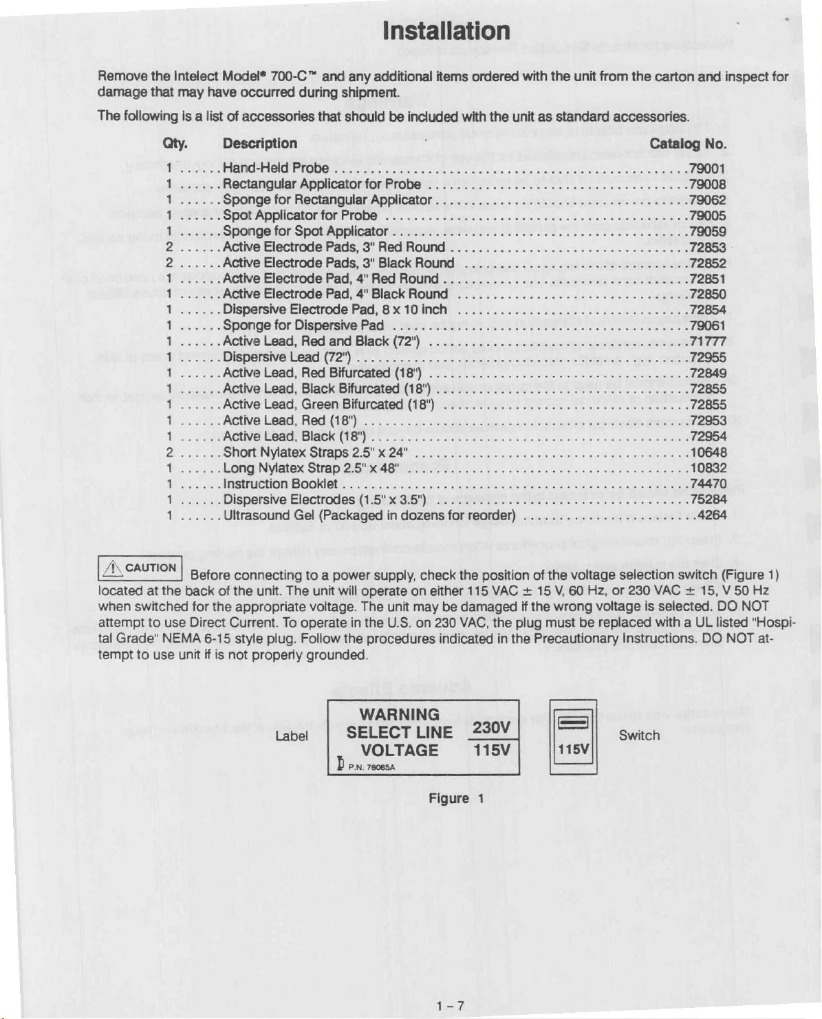
Before
back
for
the
Direct
6-15
if
is
connecting
of
the
unit.
appropriate
Current.
style
plug.
not
properly
to a power
The
voltage.
To
operate
Follow
grounded.
unit
will
operate
The
in
the
the
procedures
supply,
on
unit
may
U.S.
WARNING
Label | SELECT
VOLTAGE
Ď
P.N.
76065A
check
either
be
on
230
indicated
LINE
Figure
the
position
115
VAC + 15
damaged
VAC,
the
in
_290V
115V
1
of
the
V,
if
the
wrong
plug
must
the
Precautionary
=
|
115V
voltage
60
Hz,
voltage
be
replaced
selection switch
or
230
VAC + 15, V 50
is
selected.
with a UL
Instructions.
Switch
(Figure
DO
listed
DO
NOT
NOT
1)
Hz
"Hospi-
at-
Page 11
Ultrasound
Specifications
AA
SELL
Frequency
Duty
Pulse
Ultrasonic
Output
Temporal
Input
Output:
1.
2.
SL
Timer
1.
A
È 和 mde
RE
3. 1 minute
Applicator:
Cycle...
Repetition
Meter Accuracy.
Power
Continuous: 1 MHz
Pulse: 1 MHz
Accuracy:
Less
than
less
than 5 minutes
9
x
10
minutes
Rage...
Power
Peak
/Average
Requirements:
signal
РЕ
0.5
seconds
i i
es
for
jme’
settings
Intensity
.....
signal
that
modulated
for
settings
greater
…1.0
MHz + 5%
...
100%
(continuous
50% + 10%
20% + 10%
用
100
Hz + 20%
…
Variable
... + 20%
Ratio.................
is
on
as
100%
by
a
than
long
the
2:1 + 20%
5:1 + 20%
...
115
V/60
230
V/50
as
the
timer
100
Hz
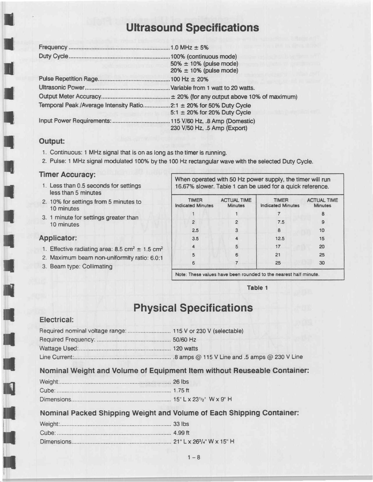
When
16.67%
Indicated
rectangular
TIMER
(pulse
(pulse
from 1 watt
(for
any
output
for
50%
for
20%
Hz,
.8
Amp
Hz,
.5
Amp
is
running.
operated
pe
slower.
Minutes
1
に
25
with
Table 1 can
3.5
mode)
mode)
mode)
to
20
watts.
above
Duty
Cycle
Duty
Cycle
(Domestic)
(Export)
wave
with
50
Hz
ACTUAL
TIME
Minutes
1
e
3
4
10%
the
selected
power
be
used
of
maximum)
supply,
for a quick
TIMER
indicated
7
ao
8
12.5
Duty
Cycle.
the
timer
.
Minutes
Е
will
run
reference.
ACTUAL
TIME
Minutes
8
2
10
15
Es
EE
PO
EE
1.
Effective
2.
Maximum
3.
Beam
type:
Electrical:
Required
Required
Па
Nominal
Dimensions..
nominal
Frequency:
Weight
Nominal
Weight:..
Cube:....
Dimensions.
radiating
beam
gl
Collimating
voltage
еее
Packed
area:
8.5
cm? + 1.5
non-uniformity
irk
ratio:
Physical
range:
............................
and
Volume
Shipping
Weight
cm?
6.0:1
of
Equipment
and
ーー
È 5
5
6 2
Note:
These
values
have
Specifications
115 V or
…
50/60
....
120
.8
a.
18"
Volume
....
33
…
4.99
っ
21"
230 V (selectable)
Hz
watts
amps @ 115 V Line
Item
without
LX
23%"
Wx
9"
of
Each
Ibs
ft
Lx
26%/"
Wx
15"H
о
been
rounded
Table
and
.5
amps © 230 V Line
Reuseable
H
Shipping
m
T
25
to
the
nearest
1
Container:
Container:
half
minute.
»
=
30
BS
1-8
Page 12
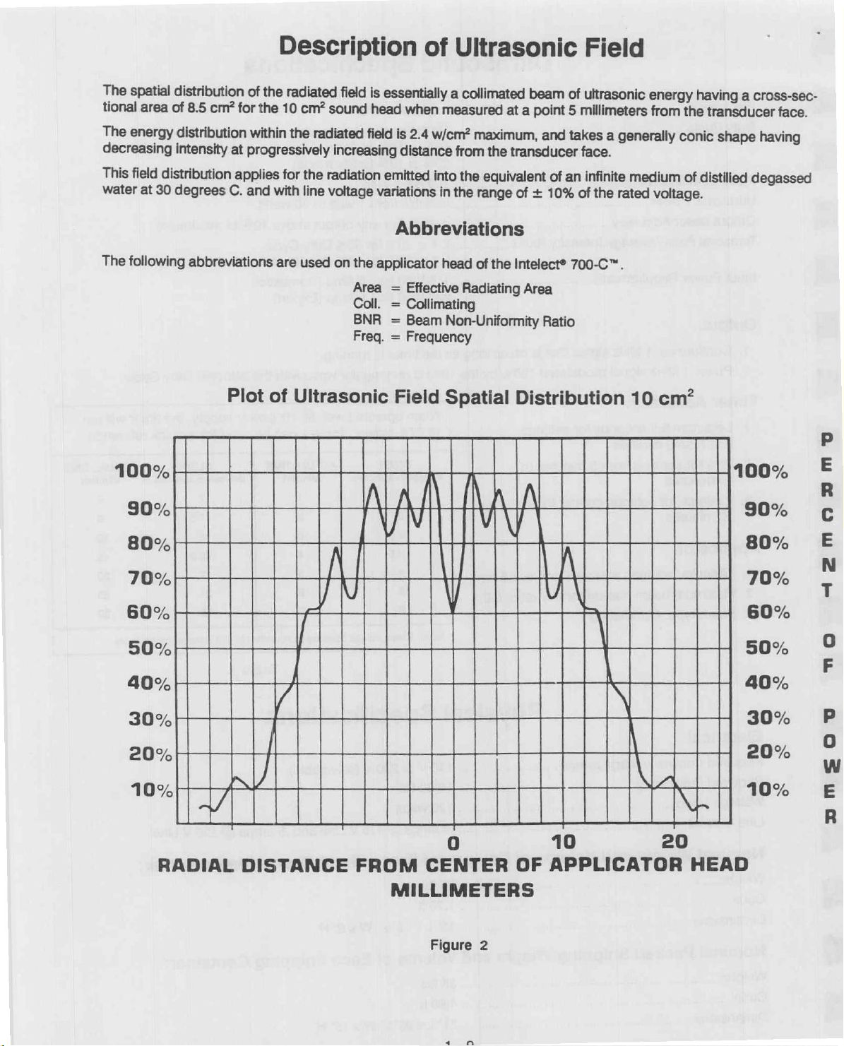
The
spatial
tional
area
The
energy
decreasing
This
field
distribution
water
at
30
The
following
distribution
of
8.5
distribution
intensity
degrees
abbreviations
of
cm?
for
at
progressively
applies
C.
and
Plot
Description
the
radiated
the
10
within
for
with
are
of
the
Ultrasonic
cm?
sound
radiated
increasing
the
radiation
line
voltage
used
on
field
the
Area = Effective
Coll. = Collimating
BNR = Beam
Freq. = Frequency
of
is
essentially
head
when
measured
field
is
2.4
w/cm?
distance
emitted
variations
applicator
into
in
Abbreviations
head
Field
Ultrasonic
a
collimated
maximum,
from
the
equivalent
the
range
of
Radiating
Non-Uniformity
Spatial
beam
at
a
point
and
the
transducer
of
of
+
10%
the
Intelect®
Area
Ratio
Distribution
Field
of
ultrasonic
5
millimeters
takes
a
generally
face.
an
infinite
of
the
rated
700-C™.
energy
from
medium
voltage.
10
cm?
having
the
transducer
conic
of
distilied
a
shape
cross-sec-
face.
having
degassed
100%
90%
80%
70%
60%
50%
40%
30%
20%
10%
Y
RADIAL
DISTANCE
FROM
CENTER
0
10
OF
APPLICATOR
100%
90%
80%
70%
60%
50%
40%
30%
20%
NE
20
HEAD
10%
で
や
mogm
コン
ο
π
mmsou
MILLIMETERS
Figure
2
Page 13
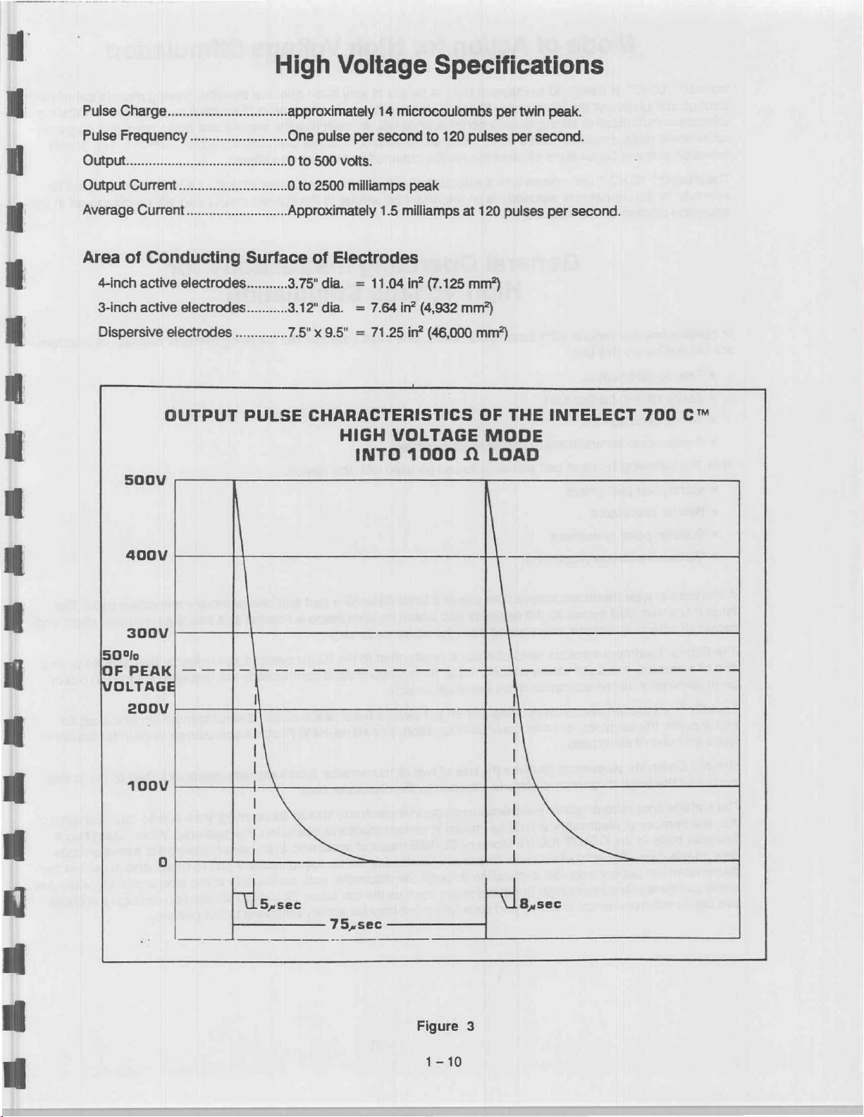
High
Voltage
Specifications
PulseCharge................................
AverageCurrent...........................
Area
of
Conducting
4-inch
active
electrodes...........
3-inch
active
electrodes...........
Dispersive
500V
electrodes
OUTPUT
..............
approximately
One
pulse
0
to
2500
Approximately
Surface
PULSE
of
3.75"
3.12"
7.5" x 9.5" = 71.25
CHARACTERISTICS
14
per
second
milliamps
1.5
Electrodes
dia. = 11.04
dia. = 7.64
HIGH
INTO
microcoulombs
to
120
pulses
peak
milliamps
in?
in?
(4,932
in?
VOLTAGE
1000
at
(7.125
mm?)
mm?)
(46,000
A
per
120
mm?)
OF
MODE
LOAD
twin
per
second.
pulses
THE
peak.
per
second.
INTELECT
700
C™
400V
300V
5090
FPEAM|
VOLTAGE
200V
100V
一
一 一 一 二
ous,
一
一 一 一 一 一
75,sec
一 一 一 一 -
eee
Ps
Figure
1-10
3
Page 14

Mode
of
Action
for
High
Voltage
Stimulation
Intelect®
through
effects
700-C™
stimulation
are
minimized
reciprocate
selection
The
selection
operation
In
considering
are
©
e
Also,
®
of
Intelect®
of
section
obtainable
Tetanic
Surge
tetanic
©
Twitch
©
Reciprocate
the
following
Monopolar
e
Bipolar
e
Specific
e
Multiple
is
designed
of
the
at
rates,
muscles
these
parameters
700-C™
the
the
by
proper
of
this
various
this
unit
size
unit:
contraction.
contraction.
contractions.
contractions
types
placement.
placement.
point
placement.
electrode
placement.
to
deliver a train
large
motor
strong
can
muscle
be
either
dictates
comes
manual.
with a selection
electrode
is
General
High
stimulation
to
of
pad
parameters,
two
or
placements
of
pulses
fibers.
By
limiting
contraction
twitched,
the
results
obtained
of
an
important
levels.
tetanized,
different
parameter
Operating
Voltage
one
more
muscles.
can
be
used
of
very
short
duration
the
pulse
duration
By
selecting
or
surge
for
various
size
the
tetanized
conditions.
electrodes
in
the
desired
Instructions
Stimulation
must
note
that
the
with
this
device:
thereby
of
the
stimulus,
appropriate
at
regular
as
well
as a hand-held
results
following
forms
causing
stinging
pulse
intervals.
and
will
for
of
muscle
rates
be
discussed
muscle
contractions
and
irritating
and
surge
or
The
proper
probe.
The
in
contractions
the
A
Monopolar
large
dispersive
group
muscle
The
Bipolar
end
of a muscle.
point
stimulation
Specific
motor
Point
point,
types and
Multiple
leads
The
this,
diameter
area.
placements
active
sive
Electrode
and
surface
the
number
In
this
pads
pad
type
contractions
treatment
placement
trigger
use
of
the
large
area
pads
in
case,
the
are
is
not
detrimental
treatment
pad
serves
involves
It
is
used
where
for
re-education
involves
point,
or
electrodes.
placement
dispersive
ratio
of
active
of
electrodes
the
CONTINUOUS
the
ratio
patient
placed
may
over
involves
as
the
are
required
pads
specific
of
other
involves
electrode
electrodes
should
of
active
feel
stimulation
high
threshold
to
active
the
use
opposite
from
of
equal
rather
an
individual
using
any one
body
point
the
use
attached
be
limited
Mode
to
dispersive
pad
stimulation
of a large
pad
where
the
active
size
attached
than
muscle.
of
location.
of
two
to
to
dispersive
in
or
SURGE
electrodes
through
areas
such
dispersive pad and
no
stimulation
pads
only.
to
the
group
muscle
several
See
or
four
the
dispersive
hand
Hand-Held
smaller
electrode
certain
mode
the
dispersive
as
but
may
modes
of
will
the
low
be
treatment,
is
needed
dispersive
contractions
probe
electrodes
Probe
3-inch
lead.
should
of
be
back.
slightly
be
operation.
approximately
pad,
particularly
This
annoying
one
or
and
Accessories
diameter
no
more
For
both
pads
slight
more
small
active
and
where a treatment
active
leads,
then
are
required,
for
stimulation
section
pads
attached
than
one
example:
become
one
in
to
the
When
the
three,
stomach
stimulation
to
the
patient.
pads.
placed
such
as
of a specific
for
to
the
to
four.
using
active
and
in
area,
through
The
effect
and
at
each
in
motor
details
active
Because
two
surface
certain
when
the
disper-
of
of
4"
pad
the
Page 15
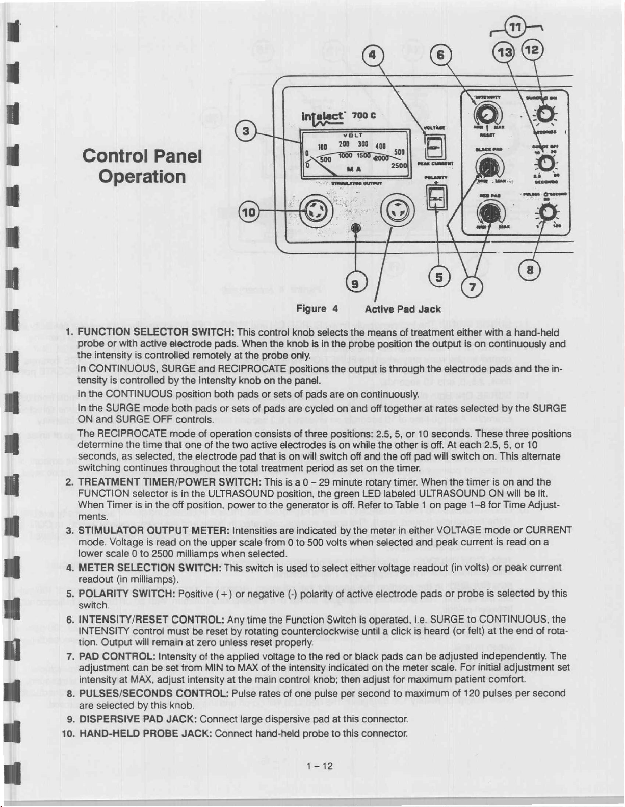
Control
Operation
.
FUNCTION
probe
or
with
the
intensity
In
CONTINUOUS,
tensity
In
In
ON
The
determine
seconds,
switching
.
TREATMENT
FUNCTION
When
ments.
.
STIMULATOR
mode.
lower
.
.
.
tion.
.
.
.
10
.
is
the
CONTINUOUS
the
SURGE
and
SURGE
RECIPROCATE
Timer
Voltage
scale 0 to
METER
readout
SELECTION
(in
POLARITY
switch.
INTENSITY/RESET
INTENSITY
Output
PAD
CONTROL:
adjustment
intensity
PULSES/SECONDS
are
selected
DISPERSIVE
HAND-HELD
Panel
SELECTOR
active
is
controlled
SURGE
controlled
mode
OFF
the
time
that
as
selected,
continues
TIMER/POWER
selector
is
in
the
OUTPUT
is
read
2500
milliamps).
SWITCH:
control
will
remain
Intensity
can
be
set
at
MAX,
adjust
by
this
PAD
PROBE
SWITCH:
electrode
remotely
and
by
the
Intensity
position
both
pads
controls.
mode
of
operation
one
of
the
electrode
throughout
is
in
the
ULTRASOUND
off
position,
METER:
on
the
milliamps
SWITCH:
Positive
CONTROL:
must
be reset by
at
zero
of
the
from
MIN
intensity
CONTROL:
knob.
JACK:
Connect
JACK:
This
pads.
When
at
the
RECIPROCATE
knob
both
pads
or
sets
of
consists
the
two
active
pad
the
total
SWITCH:
power
Intensities
upper
scale
when
selected.
This
switch
(+)
or
negative
Any
time
rotating
unless
reset
applied
to
MAX
at
the
main
Pulse
large
Connect
hand-held
Figure
control
the
probe
knob
knob
only.
positions
on
the
panel.
or
sets
of
pads
are
of
electrodes
that
is
on
will
treatment
This
is a 0 — 29
position,
to
the
generator
are
indicated
from 0 to
is
used
(-)
polarity
the
Function
counterclockwise
properly.
voltage
of
rates
the
intensity
control
of
one
to
dispersive
probe
selects
is
in
pads
are
cycled
three
positions:
is
switch
period
the
500
volts
to
select
Switch
the
red
indicated
knob;
pulse
pad
4
the
the
minute
green
is
at
to
Active
the
probe
output
on
continuously.
on
and
on
while
off
and
as
set
rotary
LED
off.
Refer
by
the
when
either
of
active
is
until a click
or
black
then
adjust
per
second
this
connector.
this
connector.
Pad
means
on
position
is
through
off
together
2.5,
5,
the
other
the
the
timer.
of
or
off
timer.
labeled
to
Table 1 on
meter
in
selected
voltage
electrode
operated,
pads
can
on
the
meter
for
to
maximum
Jack
treatment
the
output
the
electrode
at
rates
10
seconds.
is
off.
At
pad
will
When
ULTRASOUND
page
either
VOLTAGE
and
peak
readout
pads
or
i.e.
SURGE
is
heard
be
adjusted
scale.
maximum
either
is
on
selected
These
each
switch
the
timer
1-8
current
(in
volts)
probe
to
(or
felt)
For
patient
of
120
with a hand-held
continuously
pads
and
the
by
the
SURGE
three
positions
2.5,
5,
or
10
on.
This
alternate
is
on
and
the
ON
will
be
lit.
for
Time
Adjust-
mode
or
CURRENT
is
read
ona
or
peak
current
is
selected
by
CONTINUOUS,
at
the
end
of
independently.
initial
adjustment
comfort.
pulses
per
second
and
in-
this
the
rota-
The
set
1-12
Page 16

o A 개
ê
11.
βρες
SURGE
E
À
-.
a
28.
mi
application
SURGE
control
are
inoperative
tions,
2.5,
12:
SURGE
seconds
Example: A surge
SURGE
13.
between
14.
ULTRASOUND
ultrasound
ULTRASOUND
15.
transducer
16.
ULTRASOUND
at
the
transducer
TINUOUS
17
DUTY
CYCLE
100%
CONTINUOUS:
sinusoidal
50%
PULSED:
ses
per
between
20%
PULSED:
per
second.
tween
pulses.
POWER
IN
MODE:
OFF,
knobs
ON:
to
OFF:
0.5
The
independently
of
high
voltage
the
user
work
only
when
the
5,
and
10
seconds.
Both electrode
60
seconds.
time
The
rest
and
60
seconds.
INTENSITY/RESET
power
(sound
being
ON
head).
LED:
OUTPUT
(sound
(100%)
mode
can
when
An
of
period
delivered.
average
i
1
FR
INTE
timed
stimulation.
achieve
various
the
FUNCTION
FUNCTION
pads
or
automatic
10
seconds
between
Anytime
This
Green
DISPLAY:
head).
The
power
selector
set
CONTROL:
LED
This
upper
SELECTOR:
In
this
position
waveform
second.
pulses.
This
at a frequency
In
this
position,
This
produces
In
this
position,
produces
of 1 MHz
the
operator
rectangular
the
operator
rectangular
WATTS
i
in
15
29
1183320,
IN
W/CM:
2
NSITY
Figure 4 (continued)
SURGE
By
setting
degrees
of
pads
ramp
on
creates a 3.3
surges
ON
the
of
selector
switch
are
up
is
included
is
independently
and
SURGE
muscle
switch
is
in
activated
second
Rotating
the
is
on
display
scale
is
displayed.
the
operator
can
pulses
can
pulses
function
when
shows
is
nominal.
select
select
of 2 milliseconds
switch
ultrasound
the
calibrated
In
PULSED
can
select
an
of 5 milliseconds
an
SURGE
the
in
the
this
amount
ultrasound
ultrasound
OFF
ON
time
fatigue.
is
in
the
PROBE,
for a time
surge
ramp
from 0 intensity
selected
control
is
operated,
power
of
in
Watts
mode
an
ultrasound
duration,
duration,
functions
to a longer
NOTE:
SURGE
allow
or
SURGE
position.
CONTINUOUS
as
indicated
on
time
which
by
this
control
knob clockwise
the
intensity
is
being
transmitted
ultrasound
and
the
(50%,
output
output
with
power
lower
20%)
output
of 1 MHz
with
an
of 1 MHz
an
off
peak
that
for
greater
shorter
and
around
to
scale
period
ON
and
SURGE
The
SURGE
RECIPROCATE
the
is
Ya
of
the
maximum
with a range
increases
control
from
and
intensity
in
w/cm?.
power
knob
the
must
is
is a continuous
that
is
pulsed
off
time
of 5 milliseconds
that
is
pulsed
time
of 8 milliseconds
flexibility
than
in
the
OFF
controls
posi-
from
0.5
time selected.
intensity.
of
times
amount
be
the
of
reset.
available
In
CON-
displayed.
at
100
pul-
100
pulses
be-
18
HEAD
reaches
the
ULTRASOUND
cools
to
MAX
TEMP
approximately
approximately
LED:
ON
This
140
LED
120
Red
degrees
will
go
degrees
LED
F.
out,
F,
comes
At
the
and
the
Red
on
time
the
TREATMENT
LED
when
the
will
the
temperature
LED
comes
go
off
on,
TIMER
and
the
will
the
ultrasound
of
the
ultrasound
unit
will
continue
stop
to
run.
power
head
producing
When
will
be
(transducer)
ultrasound,
the
transducer
restored.
Page 17

The
probe
for
locating
with
intensity
The
user
should
same
hand
The
probe
electrodes
axis
by
aligning
clockwise
is a hand-held
painful
that
comes
to
to
trigger
control
be
tighten.
at
become
is
holding
with a disconnect
used
can
the
flat
surface
Hand-Held
electrode,
point
areas.
the
treatment
familiar
the
probe.
be
secured
with
of
the
Probe
with a self-contained
The
intensity
site.
Intensity
the
intensity
mechanism
by a thumbscrew.
shaft
so
on
that
intensity
control
level
is
control
it
by
the
shaft
The
is
perpendicular
Application
control,
knob
is
built
monitored
turning
which
allows
electrodes
on
the
to
the
designed
into
the
knob
for
are
for
the
handle
panel
meter.
with
the
various
prevented
thumbscrew
electrodes
treating
to
provide
thumb
from
and
rotating
before
localized
the
operator
forefinger
to
be
used.
about
twisting
the
areas
of
The
their
screw
or
the
The
following
700-C™
|
Figure
Catalog
removable
5a:
are
probe:
Hand-Held
No.
79001.
electrode
pictures
and
Probe
Includes
connector.
Accessories
descriptions
of
Figure
Catalog
disc
trigger
Catalog
accessories
the
various
5b:
Small
No.
used
for
points.
No.
for
Hand-Held
electrodes
Spot
79005.
5/8"
locating
Sponge
79059.
included
Standard
that
Electrode
diameter
motor
and
cover
with
unit.
ジイ
Probe
are
available
to
be
Figure
Catalog
disc
with
Sc:
with
gel
or
No.
used
Da
Large
79006.
crowned
lotion.
with
Spot
2"
edge
the
diameter
Intelect®
Electrode
for
use
Figure
Catalog
for
in a roll-on
5d:
No.
applying
Small
Roller
79003.
stimulation
type
Used
massage
Figure
Catalog
x
3/4"
rectangular
insulated
Electrode
to
muscles
action.
5g:
Insulated
No.
79002.
shaft.
Small
head
Figure
Catalog
applying
in a roll-on
Shaft
Electrode
crowned
with
electrically
5e:
Large
No.
79004.
stimulation
type
massage
°/16"
1-14
Roller
Used
to
muscles
Electrode
for
action.
Figure
Catalog
accurate
of
5h:
No.
points
Figure
Catalog
sponge
are
with
selection
on
5f:
No.
cover
standard
unit.
Acustim
79007.
the
body.
Rectangular
79008
Catalog
accessories
Electrode
Used
for
and
stimulation
and
very
Electrode
moist
No.
79062
included
Page 18

This
1.
High
The
section
is
Voltage
controls
1
Plug
Nameplate
Plug
the
hand-held
These
The
plugs
electrodes.
receptacle
Dial
the
PROBE,
CATE
If
selection
ON
has a built-in
build
to
release
5.
Set
the
divided
into
three
Operation
for
this
mode
the
unit into a properly
on
the
rear
active
lead
into
probe
connectors
located
is
FUNCTION
CONTINUOUS,
10
seconds.
is
from 0 to
may
POLARITY
The
other
located
SURGE,
maximum
be
will
at
ramp
longer
SWITCH
sections;
are
located
grounded
of
the
the
3-terminal
into
the
not
mate
the
ends
end
of
the
in
the
end
SELECTOR
SURGE,
then
SURGE
equal
in
3.3
than
(5)
Operating
HIGH
VOLTAGE,
on
the
left
side
outlet
of
the
unit.
receptacle.
4-terminal
incorrectly.
of
the
two
receptacle.
dispersive
of
the
black
SWITCH
RECIPROCATE
ON
to
one-third
seconds
10
seconds
to
POSITIVE
active
lead
conducting
(1)
in
(12)
and
the
time
and,
therefore,
depending
(+)
Plug
leads
the
Procedure
ULTRASOUND
of
the
front
panel.
proper
These
should
center
2.5
SURGE
setting
or
voltage
dispersive
receptacles
should
be
plugged
be
surface.
of
the
seconds,
OFF
(13)
of
the
the
total
on intensity
NEGATIVE
lead
plugged
panel
RECIPROCATE 5 seconds,
on
time
(-).
and
COMBINATION.
and
line
freguency.
into
the
are
located
into
into
the
to
the
should
time.
threshold
of
be
At
the
banana
on
the
3-inch
large
dispersive
desired
set
next.
10
seconds
muscle
of
contraction.
Refer
to
the
receptacle.
the
or
front
of
4-inch
Also,
electrode.
setting:
or
NOTE:
the
intensity
Either
RECIPRO-
The
contraction
the
unit.
active
SURGE
will
from
plug
The
start
6.
7.
.
9.
.
11.
12.
2.
Ultrasound
de
Dial
the
PULSES/SECONDS
Attach
Attach
If
going
Turn
knob
the
the
you
are
to
TREATMENT
beyond
dispersive
active
using
be
TREATMENT
Set
PAD
CONTROL
Turn
INTENSITY/RESET
click
will
take
level
of
tolerance.
If
patient
the
then
easy
When
tensity
has
others,
the
PAD
identification.
the
treatment
control
Operation
Plug
the
unit
Nameplate
pad
pad
or
the
roller
used.
TIMER/POWER
the
desired
TIMER/POWER
(7)
to
place.
After
If
the
more
sensory
or
if a stronger
CONTROL
The
is
complete,
to
reset.
into a properly
on
the
rear
of
CONTROL
to
the
patient,
pads
to
the
electrodes,
time
and
SWITCH
MAX.
CONTROL
this,
slowiy
SURGE
PAD
perception
muscle
can
be
CONTROL
grounded
the
unit.
function
used
remove
(8)
to
the
using
Nylatex
patient
unless
use a conductive
SWITCH
then
(6)
contraction
(2)
to
backing
is
not
up
turned
counterclockwise
turn
clockwise
is
used,
of
electrical
occurs
to
readjust
will
adjust
pads
or
outlet
of
the
determined
straps
you
are
going
gel
on
the
determined
to
the
desired
on.
to
until
patient
be
sure
to
stimulation
under
relative
pad
the
relative
and
proper
strengths.
return
voltage
rate.
or
the
to
the
area
total
time.
below
MIN
feels
adjust
intensity
in
one
one
electrode
intensity
probe
and
patient’s
use
the
probe
of
the
time
of
Intensity
to
the
sensation,
ONLY
active
pad
The
active
of
each
(if
used)
line
frequency.
body
weight.
with
patient
the
treatment
where
will
RESET
and
during
electrode
or
pads
pads
are
pad
individually.
to
its
its
attachments.
high
by
remain
at
position
continue
SURGE
pad
or
and
not the
color
holder
Refer
to
voltage
turning
zero
where
to
desired
ON
pads
coded
and
return
the
is
the
if
a
time.
over
other,
for
in-
Set
the
SITY/RESET
3.
Set
the
.
At
this
be
treated.
TREATMENT
CONTROL
FUNCTION
point,
you
TIMER/POWER
(14)
SELECTOR
may
begin
to
the
SWITCH
the
treatment
SWITCH
fully
(2)
counterclockwise
(1)
to
the
by
applying
to
the 0 (Off)
position.
ULTRASOUND
Intelect
position,
and
POSITION.
Ultrasound
the
Gel
to
ULTRASOUND
the
area
of
the
INTEN-
patient
to
Page 19

Operating
.
Tum
beyond
.
Select
50%
.
You
must
hazardous
.
Adjust
reach
.
If
you
the
10.
At
3.
Combination
와
Set
Attach
ο
Set
ο
Dial
Procedure — Ultrasound
the
TREATMENT
the
the
or
CONTINUOUS:
should
keep
the
the
need
off
position
the
end
desired
operating
then
the
applicator
exposure
Ultrasound
desired
to
interrupt
of
the
TIMER/POWER
time
mode
100%).
place
the
to
the
Output
output
the
(Bell
will
ring).
treatment,
and
moving
on
Operation
the
FUNCTION
the
dispersive
the
POLARITY
the
PULSES/SECONDS
SELECTOR
pad
to
SWITCH
Operation
then
backing
by
rotating
applicator
during
ultrasound
by
turning
the
meter
treatment
To
resume
the
bell
will
SWITCH
the
patient.
(5)
to
POSITIVE
CONTROL
(continued)
SWITCH
the
in
contact
the
energy.
the
(16).
for
any
(2)
up
to
the
mode
switch
with
treatment.
ULTRASOUND
Use
the
reason,
treatment
sound
and
(1)
to
the
(+)
(8)
to
the
to
the
desired
desired
the
time.
(17)
to
patient's
Failure
INTENSITY/RESET
Upper
scale
turn
the
repeat
steps
the
unit
will
COMBINATION
or
NEGATIVE
determined
treatment
the
desired
body
to
keep
the
for
Watts and
TREATMENT
4-8.
shut
off.
position.
(-).
rate.
time
by
duty
cycle
with a firm
applicator
CONTRO!
Lower
TIMER/POWER
turning
(PULSED:
uniform
moving
scale
the
knob
20%
pressure.
may
result
(14)
until
for
w/cm?.
SWITCH
to
You
you
(2)
in
to
Turn
oo
Select
position,
Turn
time
Begin
tact
sities;
the
may
CAUTION:
point
energy.
.
Continue
adding
meter
When
10.
PAD
CONTROL
desired
or
CONTINUOUS
TREATMENT
and
then
normal
the
applicator
first
the
affected
result
in
It
where
Therefore,
procedure
sufficient
indication
treatment
mode
TIMER/POWER
backing
treatment
to
ULTRASOUND
area.
Do
hazardous
is
possible
the
patient
it
is
described
gel
as
while
is
complete,
(7)
to
100%
of
ultrasound
ultrasound
up
to
the
by
applying
the
patient’s
not
maintain
exposure
that
high
may
have
suggested
required.
moving
position.
output - PULSED
in
SWITCH
desired
Intelect
body
and
then
the
applicator
to
ultrasonic
voltage
no
appreciable
to
apply
in
Step 8 above
Inadequate
the
applicator.
return
setting
the
100%
(2)
to
time.
Ultrasound
with
firm,
the
HIGH
energy.
stimulation
the
ultrasound
for
coupling
of
Intensity
ultrasound
DUTY
CYCLE
the
desired
Gel
uniform
VOLTAGE,
stationary
response
may
pressure.
over
have
to
first,
duration
is
apparent
controls
in
the
position
time
by
to
the
treatment
Adjust
while
continuously
any
significant
an
over-dosage
then
the
of
treatment
by
to
Reset,
20%
or
50%
of
the
turning
the
area
the
desired
given
area
pain
condition
stimulation.
time.
Insure
noting
variations
then
store
DUTY
selector
knob
of
moving
for
switch.
beyond
patient’s
treatment
the
extended
reduction
of
adequate
in
the
applicator
CYCLE
the
body.
Inten-
applicator
periods.
effect,
to
the
ultrasound
coupling
intensity
in
the holder.
(17)
desired
Con-
over
This
the
by
1-16
Page 20

Description
OC
Trouble
Ultrasonie
HighiVoltage:Calibration
Calibration’
MA
Surge
Ранее
PA
GCHEMALICS
Serialibecals
Figure
Shooting
Generator
Checklists.
AA
SBS
On/Offiindicaton
6
RF
Current
7
Ultrasonic
8
C4
and
C7
1
Calibration
o
aos
LE
tl.
LEO
Probe
Adaptor
Generator
Locations
Table
...-..
Ln:
ac
EE
Vl...
ai
ооо
a
for
Calibration
on
Rear
of
Contents
teo
PR
nn
а
о
пер
ао
Figures
Description
Ultrasonic
Setup
Panel
Generator
...................................
.....................................
Se
a
nee
р
Calibration
여기
ee
ο
cc
ео
e
ee
Co.
2-5
NER 2-9
се
AA
E
de
nn
авы
Kİ
easy
1
Wale
2-20
Back Cover
...............
2-3,
to
to
2-13,
es
aes
2-17,
to
Page
i 2-2
2-4
2-8
2-11
2-12
2-14
2-15
2-16
2-18
2-19
2-30
Page
2-5
2-6
2-7
Table
2a
WhOUble’SHOOLING
21)
ОЦЕНИ
Schematic
1
Timing
2
Timing
3
Truth
Tables
ON'andiOFElindicator
(Surge:
4
Intelect®
5
Intelect?
6
Board,
7.
Electrical
8
Electrical
9
Electrical
10
11
Electrical
Interconnection
12
Diagram
Diagram
for
700-C™
700-C”
Intelect?
PC,
Schematic,
Schematic,
Schematic,
Schematic,
ee
О
of
Surge
of
Pulse
Logic used
Cabinet
Panel
Back
700-C""
Intelect*
PCB,
PCB
Front
Diagram,
Tables
Description
ое
Schematics
Description
Circuit
Generation
Assembly
Assy.
Intelect*
.......................................
in
Intelect®
Ds
Assembly
72802
700-C"“
Supply
Pwr
OSC.
Panel
PCB,
700-C"“
ορ
ο
οσο
ао
Circuit
....................................
..............................
700-C™
τον
.................................
.
ES
Int.
Power,
Intelect®
...........................
ο
do
72542A
50w
SMP
10cm’,
700-C™
Voltage
Dual
ео
AE
çe
nee
o
...................
S73436-D
10cm,
71407-E.......
ES
S74354-A
...................
mke
een
неее
TESS
e
......
mis
...
ES
SR
2-20,
2-22,
2-24,
2-26,
2-28,
Page
2-3
2-4
Page
2-13
2-14
2-15
2-16
2-17
2-18
2-21
2-23
2-25
2-27
2-29
2-30
Page 21

.
To
fully
It
is
recommended
authorized
of
any
major
.
The
following
A.
Power
B.
Transducer
insulation
C.
Transducer
stainless
D.
LED's.
maintain
servicing
component.
items
cord
is
steel
Check
Maintenance
compliance
that
dealer
should
and
plug.
(applicator)
intact.
(applicator)
face.
each
with
all
Chattanooga
for
repairs
(See
section
be
checked
Check
Cable.
Face.
function
Federal
to
Check
Check
to
see
and
Regulation
Group,
or
for
at
make
if
Inc.
recalibrations.
Calibration
least
monthly
sure
the
to
make
to
see
that
the
LED
Service
Title
21
(21
Ultrasound
It
is
also
Procedures.)
to
insure
cord
is
not
sure
the
cable
there
is
no
is
on
when
you
Instructions
CFR)
this unit
Products
recommended
proper
frayed,
kinked
is
flexible,
build-up
are
using
must
be
returned
after
operations
or
free
of
gel
or
that
be
recalibrated
to
the
the
of
this
has
torn
of
kinks,
foreign
function.
annually.
factory
replacement
unit:
or
cut
not
material
or
insulation.
frayed
on
an
or
and
the
repair
that
—
Page 22

Trouble
Shooting
CAUTION:
The
following
sibly
happen
No
Power
Unit
has
output.
U.S.
output
about
tensity
There
is
Technician.
problems
to
your
PROBLEM
to
unit.
power
half-scale
is
set
but
meter
or
at
maximum.
an
electrical
and
solutions
Intelect®
no
Ultrasound
only
indicated
less
when
shock
700-C™.
In-
hazard
are
presented
POSSIBLE
Unit
not
No
power
Internal
Loose
Applicator
Applicator
present
connection
with
to
assist
plugged
to
the
fuse
blown.
cable
cable
MALFUNCTION
in.
receptacle.
loose.
broken.
cover
you
inside
removed.
in
solving
unit.
Refer
some
Plug
Check
or
Check
fuses.
amp
ly
only
Check
proper
tacles
Replug
Replace
same
servicing
of
the
in
blown
picofuses
board.
by a Qualified
to a Qualified
problems
REMEDY
unit.
for
tripped
fuse
3/s
amp
Check
This
internal
seating
and
for
cable
applicator
type
of
the 3 amp
applicator.
that
could
circuit
on
the
facility
(2) & Ve
on
should
connections
of
broken
into
amp
the
power
be
Service
plugs
wires.
the
shield
only
and
in
with
Service
pos-
breaker
circuit.
(2)
'/2
supp-
done
Tech.
for
recep-
box.
the
When
unit
is
energized
Temp
LED
(red)
lights
sounds.
Timer
will
not
set.
Table
2a
Head
and
Max.
beeper
Oscillator
Crystal
Shorted
Water
Timer
detuned.
damaged.
applicator
in
applicator
knob
loose.
cable.
head.
Recalibrate.
Replace
plicator
Check
meter.
replace
type.
Remove
dry
plicator.
replace
Remove
tighten
fully
the
Align
with
scale
let.
tion
transducer
and
recalibrate.
the
cable
If
the
the
cable
the
out
the
inside
If
the
it.
Consult
cap
the
collet.
clockwise
collet
so
the
white
the
29
MIN.
and
re-tighten
Perform
procedure.
head
with
an
cable
is
shorted,
with
the
transducer
of
the
O-ring
on
that
section 4 of
the
Rotate
and
the
line
mark
is
the
factory.
knob
then
knob
of
the
on
the
defective,
in
the
ohm-
same
head
and
ap-
and
the
timer
loosen
is
free.
knob
the
timer
knob
col-
calibra-
ap-
Page 23

No
stimulation
electrode
PROBLEM
out
pads.
of
both
POSSIBLE
Intensity
reset
changed.
reset
each
control
after
after
time
MALFUNCTION
has
Function
Also
Intensity
timer
has
unit
started.
not
been
selector
must
timed
out
was
be
or
Operate
REMEDY
reset
switch.
No
stimulation
Too
much
dispersive
No stimulation
probe.
Treatment
No
meter
out
of
one
stimulation
pad.
out
of
hand-held
timer
malfunction.
readout.
out
pad.
of
Dispersive
Both
pads
Malfunction
Internal
Broken
Pad
Poor
Small
surface
Dirty
Too
Dispersive
Dispersive
Dry
Probe
Voltage
down.
Timer
Intensity
wire
wires
to
broken.
fuse
wire.
control
patient
area
only
is
conducting
dispersive
much
active
pad
wire
sponge
is
defective.
control
broken
control
is
broken.
active
electrode
on
circuit
blown.
at
minimum.
contact.
8" x 10"
pad.
pad
is
not
is
broken.
on
probe
on
probe
internally.
not
board.
black
stimulation.
surface.
on
patient.
electrode.
is
turned
reset.
Replace
Replace
Replace
Check
Replace.
Check
Check
Move
that
with
thigh).
Clean
replace
Use
use
electrodes;
cate
Surge.
Place
Repair
Moisten
Repair
Adjust
Replace
Reset,
dispersive
active
circuit
3/s
(2) & a
control
for
dispersive
the
entire
patient
with
pad.
smaller
one-half
instead
dispersive
or
replace.
sponge.
or
replace.
voltage
timer.
then
lead.
board.
amp
setting.
ample
coupling
pad
surface
(back,
soap
and
active
the
number
or
use
of
Continuous
pad
control
continue.
lead.
(2)
fuses.
medium
on
patient
is
in
contact
abdomen
water
or
electrodes;
of
unit
on
Recipro-
or
on
patient.
on
probe.
so
or
or
Yellow
not
Improper
voltage
Table
Pad
light.
or
2b
Indicator
meter
readings
peak
current.
lamps
do
in
Broken
Malfunction
Treatment
Broken
Defective
Defective
wire
meter.
lamp.
circuitry
to
meter.
of
circuit
timer
not
on
2-4
board.
on.
P.C.
board.
Resolder
Replace
factory
Turn
Replace
Replace
Replace
unit
circuit
for
on
timer.
meter.
lamp.
circuit
to
factory
wire.
repair.
for
board
board
repair.
or
or
return
return
to
Page 24

Ultrasonic
Generator
Calibration
CAUTION:
1.
Test
A.
Power
equivalent
Autotransformer,
α
Ultrasound
Oscilloscope,
Probe,
Probe,
.
Voltmeter,
πωππιοσορ
Probe,
Source
use
=
Counter,
K.
Stopwatch,
Applicator
An
electrical
should
Equipment
line
monitor
for
voltage,
current,
Digital,
temperature,
of
approximately
in
UPM-30
frequency,
current
shock
be
performed
Required
115
VAC
adjustable
Power
Meter,
Hameg
X10,
Textronix
3'/2
power
Silconix
transformer
hazard
by a Qualified
(expanded
line.
from
Ohmic
Hm
204-2
Scope,
Fluke
10
Model
low
P6021
digits,
Simpson
Model
'/2
gallon
meter
(item 3 —
MHz,
Triplet
705
is
present
scale
90%
Instruments
or
capacitance.
AC
80T-150
or
equivalent.
adapter
during
Service
voltmeter
to
110%
equivalent.
current
Model
or
of
distilled
"Test
7000
or
(see
several
Technician.
for
rated
of
rated
Model
UPM-30
probe
or
equivalent.
461
or
equivalent.
equivalent.
de-oxygenated
Setup").
equivalent.
Figure
6).
portions
line
line
of
voltage + 10%),
voltage,
or
equivalent.
(<5
PPM)
the
calibration
150
watts
water
VIZ
or
at
model
greater.
30
procedure.
WV-120B
degrees
Celsius
Calibration
or
for
2.
Instrument
A.
Remove
the
.
Remove
current
Insert
on
cover
an
the
SOLDER
shield
Preparation
the
top
cover
off
the
cabinet.
five
#6
truss
probe
adaptor.
RF
current
box located
HERE
RF
PHONO
of
the
head
probe
on
INSULATE
PLUG
unit
by
screws
adaptor
the
rear
removing
on
back
between
panel.
LL
the
six
panel.
the
ultrasound
The
adaptor
A
The
Ll
#6
back
truss
head
panel
can
applicator
construction
= =
screws
now
cable
is
shown
1/2"
SOLDER
(three on
be
tilted
and
the
in
Figure
16
AWG
BUS
WIRE
HERE
each
side)
outward
RF
phono
6.
SOLID
and
for
inserting
receptacle
lift
Figure
6
Page 25

Ultrasonic
CONNECT
To
115 V 80
HZ
1230 V 50
POWER
SOURCE
Generator
HZ)
AUTOTRANSFORMER
Calibration
м
ae
com
(continued)
98-132
(196-264
0 一 一
VOLTAGE
VAC
vac)
DI
LINE
4
MONITOR
ele
Intelect?
=
700-C
UPM-30
ULTRASOUND
POWER
METER
3.
Test
Setup
A.
Connect
C.
Set
AC
D.
See
OHMIC
4.
Timer
Test
A.
Using a stopwatch,
and
29
B.
If
the
timer
knob
so
C.
Repeat
after
the
5.
Check
A.
B.
Power
Rotate
Connect
board
the
test
input
voltage
Instructions
and
Adjustment
min.
See
accuracy
that
the
steps
4.A
timer
times
Supply
Intensity
the
DC
and
measure
setup
as
shown
with
the
clinical
check
the
specifications
is
out
of
white
line
on
and
check
also
out.
knob
fully
counterclockwise
digital
voltmeter
the
12
VDC
in
Figure
7.
autotransformer
Engineering
accuracy
in
specification,
the
output.
of
the
Section 1 page
rotate
knob
is
aligned
that
the
white
to
the
pins 1 (+)
It
should
Figure
to
115
notes
timer
line
and
the
7
(230)
AN-330
with
time
1-8
for
required
the
timer
with
the
on
the
timer
and 2 (-)
be
between
VAC
for
operation
settings
knob
29
minute
knob
to
its
on
connector
11.5
line
monitor
of
of 1 min., 5 min.,
timer
accuracy.
fully
clockwise
mark
on
is
aligned
fully
VDC
with
clockwise
J1
and
the
UPM-30
the
the
position.
which
12.5
and
timer
"0"
connects
VDC.
US.
10
min.,
adjust
the
scale.
position
Power
20
collet
in
the
to
the
Meter.
min.,
on
the
scale
control
6.
Adjust
A.
D.
Select
pin
.
Adjust
should
Adjust
pulse
Select
Select
the
20%
#2
the
the
width
50%
100%
Duty
Cycle
Duty
Cycle
(com.).
time
base
be
between 8 and
scope
of
7.9
Duty
Cycle
Duty
and
Check
and
of
the
12
time
base
divisions.
and
Cycle
and
Pulse
Frequency
connect
oscilloscope
msec.
for
adjust
observe
the
10
divisions
R4
on
that
oscilloscope
voltage
to 1 msec/div
of
one
cycle
the
control
the
signal
board
is a DC
and
measure
of
the
for a pulse
level
probe
signal.
less
to
pin
the
On
width
than
#3
(signal)
period
the
control
of
.5V.
of
the
100
board,
4.7
divisions.
and
ground
Hz
signal.
adjust
clip
to
It
R5
for
a
Page 26

7.
Check
A.
Connect
the
B.
Rotate
nel
and
Adjust
the
voltage
the
scope.
the
scope
probe
Intensity
The
current
to
control
waveforms
RF
Oscillator
the
outside
should
probe
around
conductor.
clockwise
be
the
as
you
center
observe
conductor
within 5 degrees
the
of
being
of
voltage
in
the
current
and
current
phase
probe
waveforms
and
oscillation
adaptor
on
should
and
the
be
connect
dual
chan-
stable.
Repeat
Adjust
step
C4
through
correction
50%).
Replace
stainless
7-B
and
with
the
C7
through
hole
50%
duty
access
caps
its
on
cycle
hole
rear
rear
and
on
the
panel
panel.
then
with
rear
panel
access
Figure
20%
hole
duty
(see
fig. 3
for
oscillation
8
cycle
for
selected.
location,
stability
remove
in
the
hole
pulse
caps)
modes
for
phase
(20%
and
8.
9.
Check
A.
Select
necessary
B.
Select
53%
Output
A.
With
meter,
Reapply
Adjust
Adjust
mo om
Check
at
and
Adjust
20%
50%
duty
Meter
electrical
to
electrical
the
the
the
the
power
U.S.
2.0
5.0
10.0
15.0
20.0
Modulated
Duty
Cycle
to
obtain
Duty
Cycle
cycle.
Calibration
power
align
the
Intensity
meter
calibration
accuracy
levels
Meter
W
W
W
W
W
and
21%
and again
removed,
meter
power
control
of
the
listed
RF
Duty
observe
duty
the
cycle.
observe
adjust
pointer
to
the
on
with
unit
the
and
front
potentiometer,
output
below.
meter
UPM-30
Minimum
1.72
W
43W
8.6W
12.9W
17.2
W
Cycle
duty
cycle
the
modulated
the
mechanical
"0"
on
the
select
100%
panel
to
R18,
by
comparing
Indication
Maximum
2.28
5.7W
11.4W
17.1
22.8
of
meter
obtain
for
an
W
W
W
the
100
Hz
RF
waveform.
zero
adjustment,
dial.
duty
cycle.
20
watts
indication
its
indication
modulated
Readjust
located
output
of
20
to
power
watts
the
RF
on
on
power
waveform.
R4
as
necessary
on
the
front
the
UPM-30.
the
front
panel
indicated
Readjust
to
panel
under
output
on
the
UPM-30
R5
as
obtain
the
meter.
Page 27

Ultrasonic
F.
Vary
remains
G.
Select
average
Generator
the
line
voltage
within
50%
Duty
power
Calibration
the
limits
Cycle
indication
(continued)
from
98
listed
and
on
VAC
above.
check
the
UPM-30
(196
the
peak
VAC)
listed
to
132
output
below.
VAC
meter
(264
VAC)
accuracy
and
check
by
comparing
that
its
the
output
indication
power
to
the
H.
POWER = (%
U.S.
Peak
2.0
5.0W
10.0
15.0
20.0
Select
20%
UPM-30
indications
U.S.
Meter
Peak
2.0W
5.0W
10.0W
15.0
20.0
Meter
Power
W
W
W
W
Duty
Power
W
W
DUTY
Cycle
as
CYCLE)
Minimum
.86W
2.15
4.3W 5.7W
6.5
8.6
and
check
listed
below.
UPM-30
Average
Minimum
.34
86
1.72W
2.58
3.44W
UPM-30
Average
W
W
W
the
Indication
Power
W
W
W
(POWER
accuracy
PEAK)
Indication
Power
Maximum
1.14W
2.85
W
8.5
W
11.4
W
of
Maximum
46W
1.14W
2.28W
3.42W
4.56
W
the
output
meter
by
comparing
its
indication
to
the
10.
Check
A.
Apply
B.
Allow
ultrasound
C.
After the
mum).
D.
Let
the
The
Head
Maximum
maximum
the
applicator
energy
head
the
Head
surface
temperature
temperature
power
to
is
cools,
Maximum
must
Temp
at
100%
heat
removed
power
Temp
of
the
be
between
Trip
duty
until
the
from
will
be
control
stainless
cycle
to
Head
Maximum
the
head
reapplied
cycle
on
steel
130
degrees
the
ultrasound
(the
output
to
the
and
off 3 times
head
immediately
F.
and
Temp
LED
meter
head (LED
150
degrees
applicator
lights,
indication
goes
and
after
with
the
off
and
then,
the
F.
beeper
will
meter
with
Head
it
coupled
sounds
go
to
zero).
indication
the
temperature
Maximum
to
the
and
Temp
air.
the
returns
probe,
LED
to
maxi-
check
lights.
Page 28

High
Voltage
Calibration
Equipment
de
Oscilloscope:
Freguency
Digital
ARON
Stop
Surge
の
needed:
Counter
Voltmeter
Watch.
On
and
Precalibration
Adjust
the
Front
R118
S7
S8
R121
S6
S5
S2
S3
$4
following
Panel
Pulse
Surge On
Surge
Intensity
Treatment
Power
Function
Meter
Polarity
Pad
(Front
10
MHz
with
(DVM).
Off
indicator.
setup
controls
Controls
Rate
Control
Off
Control
Control
Switch
Switch
Selector
Switch
Control
Panel)
or
greater
period
to
the
Control
Timer
bandwidth
function
(1
designated
60
pps
5
sec.
5
sec.
Reset
Zero
Off
Continuous
N/A
Positive
CW
with
10:1
sec.)
and
positions
(100%)
probe.
time
interval
listed
below
function
before
applying
(10
sec.);
power
i.e.,
Simpson
to
the
2725.
unit
under
test:
Calibration
de
Power
Set
lead
DVM
tive
.
Meter
Set
trol
Q17
Return
.
Reciprocate
Set
tach
signal
Supply
DVM
to
+15
should
lead
of
Voltage
Meter
full
clockwise.
with
Intensity
frequency
other
is a 15
Voltage
on 20
VDC
volts
read
DVM
Adjustment
Selector
DVM.
As
control
Time
counter
lead
to
volt
Adjustment
range.
supply
15
to
Adjust
(Anode
volts
pin
14
in
Volts
R70
intensity
to
Adjustment
on 1 KHz
TP1
(pin 3 of
peak-peak
Attach
+ .02
of
volts.
IC26
negative
of
and
position.
until
meter
varies
from 0 to
reset
position.
range.
1C13).
rectangular
D13).
Adjust
check
Adjust
reads
NOTE:
Attach
Adjust
waveform
led
of
meter
Connect
R90
clockwise
the
reference
mechanical
500
500
volts,
When
common
R46
until
to
circuit
Intelect?
until
voltage.
zero
of
volts.
Also
this
point
Intensity
lead
frequency
with
approximately
common
700-C™
DVM
It
should
meter
check
should
control
to
circuit
counter
(negative
and
turn
reads
15.00
be
10
with
intensity
collector
vary
common
50%
from 0 to
is
CCW,
reads
duty
of
side
the
Treatment
volts
+ .02 volts.
volts + .4
at
zero.
Q16
(Heat
15
knob
should
(negative
819
Hz + 20
cycle.
of
C34)
Timer
volts.
Turn
Intensity
Sink)
volts + 1
point
side
of
Hz.
and
positive
on.
Move
or
emitter
volt.
to
reset.
C34) and
NOTE:
The
posi-
Con-
of
at-
This
Page 29

High
Voltage
4.
Pulse
Set
quency
120
Rate
the
trol
pointer
in
control
time,
5.
Output
Set
(500
spacing
6.
Current
Disconnect
Adjust)
control
reading
Calibration
Rate
Adjustment
knob
on
counter
pps.)
Adjust
control
electrical
slowly
120
CW
on
the
pps
position
to 1 pps and
as
there
Voltage
Pulse
Rate
volts).
Adjust
between
Meter
for
zero
up
to
on
meter.
scope
(continued)
shaft so
CCW
rotation,
is a slight
500
that
to
pin 3 of
R1
until
gradually.
until
the
knob
at
and
adjust
Adjustment
control
R14
pulses.
Calibration
probe.
reading
volts
Turn
when
control
IC2
(or
frequency
The
period
where
the
contro!
period
exactly 1 pps
at
for
and
intensity
just
adjust
R1
R2
for a period
interaction
80
pps.
Attach
500
volts
NOTE:
on
Put
Meter
meter.
place 500
to
Make
is
cathode
counter
will
will
starts
on
the
for
120
between
oscilloscope
peak
sure
Selector
Make
sure
ohm
zero.
CCW
the
of
D1).
reads
increase
rotate
to
decrease.
dial
and
Hz
on
counter.
of
1.00
these
output.
that
switch
that
1%
resistor
pointer
Turn
120
further
seconds.
adjustments.
Check
the
intensity
on
Pulse
Hz.
Put
as
the
but
Without
tighten
Return
ground
the
oscilloscope
in
peak
is
across
the
knob
Rate
control
frequency
control
the
Repeat
waveshape
current
is
the
period
changing
knob
counter
Also
and
10:1
probes
at
zero
Intelect
120
readout
will
point
to
120
counter
rotated
on
check
volts
output.
CCW
will
not
the
position
the
shaft.
to
period
pps and 1 pps
that
probe.
of
the
are
calibrated
mode.
when
below 1 pps.
pps.
(Set
in
period
until
increase.
of
the
Set
Pulse Rate
function
adjustments
the
Pulse
Turn
intensity
double
then
pulse
Adjust
adjusting
adjust
pointer
mode.
you
reach
Then
shaft,
and
LED
control
and
before
R97
zero.
R104
Connect
exactly
Turn
the
rotate
the
set
the
control
set
Pulse
one
is
operating.
fully
the
75
this
step.
(Current
Turn
Intensity
for a 1000
fre-
on
Pulse
end
of
con-
again
Rate
more
CW
usec
Zero
ma
7.
Surge
The
surge
which
breviated
consists
The
to
10
seconds
+
5%.
TP3
1
second
check
The
the
second.
0.1
volt).
The
the
zero
500
Surge On
1C32
Calibration
surge
circuit
waveform
causes
as
the
of
Q7;
SFG
will
seconds
range
Then
set
and
with
time
the
60
surge
function
negative
SM
Intensity
and
volts,
is
Then
Do
is
the
adjust
Surge
and
the
same
lead
not
control
consists
and
the
DC
Surge
1C18,
be
calibrated
and
Surge
and
adjust
Surge
counter
with
the
second
zero
to
the
during
adjust
second
is
R68
On
to
Off
indicator
as
the
of
two
parts.
will
be
abbreviated
intensity
Modulator
32.
Off
on
counter + %.
Surge
the
R27
part
set
(Surge
10
level
to
(SM).
first.
Place
Off
time
to 1 second.
R18
until
counter
time
to
10
seconds
10
seconds
On
and
Surge
is
adjusted
negative
time
past
of
at
500
Modulator
seconds
(at
voltage previously
side
when
this
the
Surge
volts.
maximum
by
the
and
The
first
Surge
Function
change
unit
range
Then
R27.
of
point
Record
Zero
at
The
SFG
in
Surge
Attach
reads
and
and
attach
Off
times
Attach
C34.
Set
Surge
Off
as
it
will
Calibration.
that
Adjust)
Surge
Off
voltage
recorded
part
is a function
the
same
consists
mode.
time
10.0 + 0.1
Surge
adjust
R20
the
Surge On
with
positive
Surge
LED
is
cause
Measure
voltage.
a
for
to
0.5
of
ramp),
at
pin 7 of
generator
Generator
rate as
of
Q3,
4, 5, 6, 8;
R18
calibrates
interval
seconds.
On
time
to 1 second.
to
calibrate
and
the
stopwatch.
lead
of
Off
time
to
on,
adjust
an
error
with
Then
attach
reading
zero
seconds.
adjust
IC26.
which
(SFG).
The
the
surge
1C7,
the
counter
Off
DVM
10
R27
in
the
During
R32
to
Check 1 second
the
Surge
indicator
to
the
seconds
until
calibration.
DVM
the
DVM
DVM.
on
Surge
(Surge
generates
second
function.
Surge
TP2
DVM
to
Modulator
This
8,
10, 11,
On
and
Attach
time
Off
time
to
the
base
of
and
Surge On
just
voltage
pin 6 of
turn
Then
On
time
the
complex
part
is a modulator
modulator
12
and
Q24.
time.
Set
Surge
with
counter
time
with
the
interval
to
unit
A7
or
reads a null
at
pin 7 of
IC32.
Intensity
as
indicated
Drive)
counter
10.0 + .01.
under
test
pin 8 of
control
IC26
Turn
until
will
be
ab-
The
SM
On
time
on
10
counter
to
Check
and
IC7
and
to
1
(less
than
when
Intensity
control
to
by
the
pin 6 of
to
2-10
Page 30

This
completes
1.
Probe
Place
tensity
load,
.
Continuous
Red
from
Check
.
Surge
Red
from
.
Reciprocate
Visually
nately
.
Reset
Check
.
Timer
Check
the
Mode
the
unit
meter
check
and
black
zero
to
operation
Mode
and
black
zero
to
check
starting
to
see
Check
Timer
adjustment
into
the
and
the
the
operation
Mode
pad
500
volts.
of
pad
500
volts.
Mode:
period
with
that
reset
operation
phase
Probe
output
of
LED's
should
Check
pad
controls.
LED's
should
Check
2.5, 5 and
of
2.5, 5 and
the red
pad
operates
to
make
of
the
Mode.
from
the
Check
zero
current
be
lighted.
operation
Intensity
be lighted.
operation
10
Seconds
10
LED.
properly
sure
calibration.
to
see
to
500
volts.
meter
in
Check
of
current
control
Check
of
current
second
that
reciprocate
between
it
will
shut
Make
the
that
the
Probe
Check
the
probe
the
mode.
power-on-clear
meter
on
the red
should
be
set
power-on-clear
meter
on
the red
periods.
all
modes
off
at
time
following
Intensity
operation
function.
and
at
maximum.
function.
and
Red
except
while
out.
Functional
control
of
the
Polarity
varies
Check
black
pads
Check
black
pads
and
black
pad
in
reciprocate
checks:
the
Switch.
to
see
with
the
to
see
with
the
LED's
modes.
voltage
With a 500
that
intensity
500
ohm
that
intensity
500
ohm
should
on
the
load.
load.
light
in-
ohm
varies
varies
alter-
2-11
Page 31

Calibration
Check
List
Steps
Power
1:
Reference
Meter
Collector
3.
Reciprocate
Pulse
.
Output
Check
.
Current
.
Surge
Off
Surge
Surge
Supply
Voltage
of
Rate
Voltage
Waveform
Meter
Function
Time
Function
Modulator
Voltage
Voltage
Calibrate:
Check:
Adjustment.
Q16:
Check 0 to
Time
Adjustment:
Adjustment:
of
Calibration:
Generator:
Zero
Zero
Adjustment:
9.6
to
15 + 1
120
pps.
1
pps.
Pulse
Indicator
500
Output
and
Zero
1000
On
10.4
819
volts
75
mA
Time
15.00
volts + .02
volts.
volt.
Hz + 20
LED.
peak.
usec
spacing
Hz.
volts.
of
pulses.
Initial
Drive
Functional
1.
Probe
2.
Continuous
3.
Surge
4.
Reciprocate
5.
Reset
5.
Check
Safety
Tests
1.
Hi-Pot
2.
Ground
3.
Leakage
Checks
Mode
Mode
Mode
Mode
Check
Operation
2500
volts
Resistance
Current
Timer
Test
Test
2-12
Page 32

Timing
Diagram
for
Surge
Circuit
SIGNAL
EMITTER
Q7
IC
9,
PIN
PIN
11,
IC
IC
10
PIN
IC11
PING
PIN
6
Ic
10
Е
РЗ
IC
12
PIN15
IC12
PIN3
IC
12
PIN14
+
IC12
PIN
2
IC
11
PIN3
15V
«Ον
10V
6
2
5V
10V
2
5V
15V
ον
15V
ον
10V
5V
15v
OV
15V
ον
15V
OV
15V
OV
10v
sv
SURGE
NOT
SELECTED
ΣΣΣΣΙΣΣ
一
—|
ーーーー
RAMP
|
1
1
1
I
!
1
!
T
|
|
ル
ーーーーー
|
!
I
!
1
i
i
|
1
UP
i
|
T
I
|
|
I
I
|
!
1
|
!
|
URGE
se
ON
a.
Z
==
So
|
!
pa
Va
Ls
boa
08
y
|
!
Ка
|
enn
4
|
I
ν
:
I
1
1
|
!
T
|
1
:
|
em
E
キョーコ
RAMP|
UP
!
I
I
|
:
I
I
|
OL
1
1
|
T
4
1
I
|
|
!
1
1
πα
I
|
SURG
ON
1
1
1
1
1
Lo
!
I
1
1
!
i
!
|
Schematic
2-13
1
Page 33

γι-σ
Ic
PIN
IC
IC 4 PIN
IC 6 PIN
1C
IC
CURRENT
R87
IN
Q17
oqeuauos
z
COLLECTOR
2
2,
PIN
2
PIN
4
34
PULSE
6
3
10
3
4
PIN
3
RATE
tov
sv
м.
ov
bs
=
ev
E
ov
800mA
OmA
MSV
о
-50V
+500V
50
PPS,
INTENSITY
CONTINUOUS
=
1
V
Å
1
7
V
500V
MODE
1
SEC © 1
20mS
8.3
POLARITY
@
mS
@
(+)
PPS
PPS
50
120PPS
Ar
し
=
一 由 -so
エー
ゴ
ー
ロー
75
S
SETE
125
600;:S
1.5-2ms
.
7545
トー
人
500-600
NOTE:
PULSE
NOTE:
DETERMINES
uS
ABOVE
STAYS
WIDTH
80
HIGH
OF
PULSE
OUTPUT
PPS
THIS
VOLTAGE
Y
f]
A
n
1
=
uma
3
=,
글
©
шелбеа
240;
aslnd
ら
ANODE
WITH
T2
OUTPUT
ACTIVE
WITH
DISPERSIVE
INTENSITY
POLARITY
OF
D11,
RESPECT
WHT.
LEAD
VOLTAGE
PAD
RESPECT
500V
(+)
PAD
D12
TO
ov
-150V
bend
TO
+
—|
500
—
|-
7518
XA
DETAIL
OF
‘f=
OUTPUT
75:8
PULSE
È
uoIhB』gug
1Ino』IO
Page 34

Truth
Tables
for
Logic
used
in
Intelect*
700-C™
<
m
<
m
<
m
<q
m
<
m
TOT
=
Leg
z
3
TT
é
o
©
о
о
о
o
5
o
5
5
与
E
5
E
E
o
o
こ
こ
<
m
<q
m
O
O
φ
O
A
BIOUT
Oror
corr
<oocr.-
<oorr
2
o
Е
с
o
z
o
>
E
gl
らら
ーー
σ[ο
ο
τ-
τ-
Moror
Mor
or
jo
-
o
-
mjo
-
om
o
*
O
O
o
coor
5
Orr
=-
与
ro
与
rooo
5
Orro
13
10
—
—
4028
12
14
3
Schematic
2-15
INPUTS
13
roor
3
10
rroo
12
rooo
OUTPUTS
14
口
一口
口
mooro
Nocor
Page 35

+15
Surge
ON
and
OFF
Indicator
SURGE
TP2
TP3
1M
AAA
1M
.001
44)
220K
910n
2N5308
SURGE
9101
2N5308
o
v
OFF
e
YY
COM
Schematic
2-16
—
4
Page 36

Intelect®
700-C™
Cabinet
Assembly
Schematic
2-17
5
Page 37

Intelect®
700-C™
Back
Panel
Assembly
Page 38

Itelect®
700-C"
Parts
List
REFERENCE
WA
e
2
ee
Aj
sene
ve
Sie
ee
B
Mes
at eee
Duna
e
О,
mes
I
NDE
В
AA
DO
RES
ss
cate
e
ео
1
Des
IS,
Ms
Ti
DO
sra
ora
DUE
Sİ
emel
PTS
ear
OS
ME
VE
25%
(1)
|.
a6:*
(AY
«le
QI):
SOA)
e
caus
了
SRO
ae
B8
DEN
RCE.
Os
全
和
(Not
Shown) * (2)
(Not
Shown) * (1)
(Not
Shown) * (1)
(Not
Shown) * (1)
(Not
Shown) * (2)
(Not
Shown) * (1)
(Not
Shown) * (1)
sis 8 oe
seg e vino
erene e sesimiz
ue
cesse
vigora
sil
E
Te
spas
Ivana
srs o e
e
eza.
nia
aie à ss
te a 79085
GRES
Маня
Le 74958
tel.
SG
ale
wees
e
ye
nre
«JE
oak
=c
UE
νου
KU
sacre
...
...
...
...
...
...
...
vá
Ne
l
PART
No.
74284.........
24116... . .
74077.........
7900
¿soez
79087.........
79008227
A
74162.
a
.........
74356... . .. = Decal,
TAS5O
ME
73664:
soka
75642.........
cus
2538 - ilem
TIO
4354
74200
tes
еее
.........
74066.........
74203
. . . . . .
74922), . 54.55
76060
.........
rs
AO
74723 . στα,
76068...
DESCRIPTION
Top
Cover,
.……
Bezel,
Switch,
Probe,
Conn, 4 Pin
: a a Knob,
Knob,
va
Knob,
Conn, 3 Pin
Front
Meter,
Applicator,
asso
Holder,
esi
PCB,
mie
Timer,
PCB,
Meter,
Stand,
. . . Transformer,
Transformer,
Panel,
Holder,
Receptacle,
ye...
Fuse,
72535.11... № Fuse,
SODA
once
70094
76068:
TODD.
78375
70484
TAM
TOTI
.........
ος
eme
si
.........
E
orne
TL
A
76054.........
72435.........
73469.........
73960.........
73222.........
72803.........
74752.........
74753.........
σος.
cus
e
à
.
Holder
Fuse
Fuse,
Fuse,
Cover,
Filter,
Spacer,
Transducer,
Power
Fuse
Switch,
Transtr,
Switch,
Transtr,
1N5366B,
SCR
.01/600V
.015/600V
|-700-C,
17 x 59/4,
ABS
MML34HBZACOIK
1-500
No.
023-3525,
No.
023-5425
No.
021-3525,
Front
Panel
Panel,
1-700-C
In
230P
Modutec
U.S.
10
Applicator,
In
500
w/IC's
Bell,
30
Minute
In
700-C
Interface
|-500-S
Tilt,
MP40008-5,
A41-25-20
A41-80-36
Button,
Ya
Vs
Holder,
°/e
'/#
Shield,
Line,
Cord
Holder,
S60006L
|-700-C
Probe,
In
PniCmp
Amp
(250V)
Amp
(250V),
Cord,
PP-40055
Little
Amp
(250V)
Amp
(250V),
(Includes
3A/250V
!-700-C,
10
cm?
Little
Slide,
V80212SS
D45C11
Digitast
MTP8P10
39V
Zenor
Capacitor
Capacitor
Delrin,
Pnt
`
Elma
with
Elma
Overlay,
S/M/C
cm
Right
500-S
8301213
Slo-Blo
Fuse
Slo-Blo
Fuse
FET
Diode
No.
0482100
Blk
w/o
!-700-C
930368-106
Assembly
15.5
In
357001
PC
Boards)
Oscillator
357001
05Q
Ring
*
Parts
and
their
quantities
included
in
the
2=19
Repair
Parts
Support
Kit
Page 39

PCB,
0
Di
srr
그
|
“RES
—
=
ma
Ml
E
=
т:
2200,f
KTo
Аг
E
квт,
E
Intelect*
ー ト -
=
D45
put
“to
上
+
TE
cH
700-C
=
-G59-
=
è
수
>
그
5
ki
9
72502
Bi
a
l
a
č
ně
“=
τς
rel,
ear a ‘eh
C28
4403
vě
Dİ
ος
rH
ο
πα
a
ca
s
[sec
은
Ex
;
Sg
に
|.
은
RO
©
O
|
8
3
$
45
È
=
E
i
.
Er
©
ki
&-
n
TS
ad
,
vit
Sa
+405
č
cn
E
τὸ
š
o]
TE
č
Rios
tee
RT
sx
りり
e
@
0
の
44098
ex
KI
TÁ
D3
qo
の
K2
ON
on
OO
Dé
K5
az
ος
Se
-
A
т
I
로
+
cm
IT
=
πι
και
se
s
a
;
|
Schematic
2-20
7
Page 40

PCB,
Intelect®
700-C;"
72502
(continued)
da
1C25
“|
S
o
$
Pig
き
i-
pre
i:
åg
P
a”
ig
è
мы
n
1024
DI
3
8
Ic!7
Fm
S
$ +
τω
/%%
a
4
{05
et
o
Ее
Wee)
$
8
EEE
5
=
3
=
ČST
=
=
GR en
n]
Gd
Tl
GE
9
a
o
fs
мк
M
23ο
IC25
~
o
$
τοις
Mm
E
t
a”
ら
-
TCs2
e
тен
A
^
теч,
(σον
Eu
DES:
mæ
Rit
R35
g
“8
D20
wet
3
IC21
ma
ν-
sl
X)
č-
cero
we
ax
sl:
8 o
|
ma
cn
é
тео
«Te
に
1
vm
Soy
—
so
O
ES
res
AT
La
6
jé
À
U
A
co
e
Rss,
EO
4
$
fa
$
στ
432
RI
й
IC21
5
= 8
2
σον
,
|]:
m-
~
<
上
A,
을
R28
see
+
ål
cs
ar
~
το
р
ED
c+
S,
>
gs:
TP!
IE
=
es
2222
ii
o
=c2o
mæ
al
è
δι
3
-
Fr
ae
È
|
DO
—138—
m
τοι
PN7250)
+
=="
as
>
>
EH
EB
[вк
==>
o
nae
2155
ex
=
E
me
ат
4,
Ol
к =
nt
PRETEÇ
타니타
1111
m
leis
la
sx
dai
ERE
に に に
lo
|
e
T4
RI
AL
cm
a
Schematic
2-21
7
Page 41

Electrical
Schematic,
Intelect®
700-C,”
ES
72542A
Page 42

Electrical
Schematic,
Intelect®
700-C,™
ES
72542A
(continued)
aaa,
==
|
“pm
ar
vana
14)
Schematic
2-23
8
m
δα
1:
AS
1
PS
A ©
Page 43

Electrical
Schematic,
PCB
PWR
Supply
Int.
SMP
50w
10cm,
S73436-D
Schematic
2-24
9
Page 44

|
PWR
Supply
L
RIS
x
13524
Electrical
Int.
SMP
ul
Schematic,
50w
CR7
i
10cm,
ㅁ
510
PCB
S73436-D
=
(continued)
RL
4969
1
bo
wc
k
R41
SIK
[
P
cit
ey
È
la
Rag
x
|
228
р
15359
>
rs
1
2
y
15|
18]
,sv
2 | IN
lm
Sicor
Sat
Her
7.
+
w
oo!
a-|s
ol
2
1
вв
св
ca
en
|“
13
12
Lil
4
v
R26
af?
IK
i
1
4045115
a
Em
k
R32
ss
в
x
aks
|:
p
À
144148
nie
9
ko
Schematic
Es
„RB
ZVV
ka
15авин
R27
1.
x
NI
2.
14Y
Ta
주
105
y
145351
CR16
1
2-25
Page 45

Electrical
Schematic
GE
+12VFIL
+12VFIL
RFOUT
RFOUT
OSOUT
OSOUT
1
2
13
44
4
5
Ji
=
=
Ji
ul
MOTE
PCB
Assy.
ai
1.7101
OSC
Power,
tc
„вые
11
10cm’,
ES
71407-E
1NS819
+IDCF
sk
5
Jı
OSCOM
OSCOM
+IDCF
+10CF
19
11
7
8
C
=
τι
い
3
2
TB
|
E
03
assi
有
RS
oo
j
to
+
08
3
3
la
R4
ia
47
RC188
se
Ne
RS
7
J4
1
+12VFIL
OSCOM
q
ASCII
3
44
hc
.33uF
|
|
|
Ì
|
Schematic
2—26
10
Page 46

Electrical
Schematic
PCB
Assy.
ο
x
Sısrr
PR
c
å
ft
B2@PF
OSCOM
C4
OSC
1
2
Power,
s/a
10cm’,
LI
4 5
1
eww
OO
ES
OSCOM
3
n
e
71407-E
Le
>
3:59
(continued)
Ja
1 | RFOUT
2 | RFOUT
3 | OSCOM
> 4 |
OSCOM
„B
be
278
12
ss
2
DESIGNATORS
LAST
USED
R7
=
T3
D8
B
3
SPARE
=
Bae-teaarr
Hurt
+IDCF
Schematic
10
Page 47

Electrical
Schematic
Front
Panel
PCB
Intelect®
FES
00095
È
700-C,”
고
S74354-A
PULSE
RATE
RESET
INTENSITY
му
COK,
lev
REF.
+15
VOLTS
SURGE
OFF
οκ
è.
—.
="
|
πο
Чая
su
時
|
Page 48

Electrical
Schematic
Intelect®
=
Ik
Р
sw2
1
Lo
ka
A
i
ULTRASOUNO
|
RESET
>
asası
A
PCB
xi。
pes
Panel
ob
k
>
s
»
Front
一
marae
Tau
P
700-C,"
2
|
Li
|:
S74354-A
|
|
a
sE
bo
3.
rea
i
top
(continued)
sa
FUNCTION
SWITCH
호
n
a]
i
i
Se
EE
AT
E
pes
ti
Mods
4
?
TRE
prose
CONTINUOUS
Retro
2.5
由
Page 49

Interconnection
Intelect*
700-C,”
Diagram
Dual
Voltage
IS)
rn
Ti
E
n
74354
PANEL
P/N
FRONT
ASSY.
1-700C
PCB
O
|
L
]
ος
|
ASSy.
74375
ULTRASOUND
OSCILLATOR
P/N
OUT
RE
74582
PIN
JOCH'
Schematic
2-30
12
Soe
eS
EE
Page 50

O O
(Gonmacr
i
I
MODEL:
O
NSN:
DLA120-93-C-8518
©
THERAPEUTIC
lect
VOLTAGE:
FREQUENCY:
WATTS:
LINE
CURRENT,
700C
651501-284-6779
COMBINATION
115 / 230
120
WATTS
|SFRIAL
60 / 50
MAX.:
U.S
sue
ULTRASOUND
SYSTEM
VOLTS
Hz
1
AMP
(115V)
.5
AMP
(230V)
MFR:
90074
©
 Loading...