


Rev April 2006
Calibrating Your Gauge
Section Contents
Page
Accessing Embedded Procedure ..................... 2
Calibrating Your Gauge .................................... 3
About DFS Series Calibration ........................... 3
Select Gauge Model ......................................... 3
Select Calibration Units .................................... 4
Select Calibration Midpoint Value ..................... 4
Stabilize the Gauge .......................................... 4
Compression Calibration
Attaching to Compression Fixture ............... 4
“Flip Display” ................................................ 4
Exercising Loadcell ...................................... 4
Apply Zero Compression Load .................... 5
Apply Mid-Scale Compression Load ........... 5
Error Checking ............................................. 5
Apply Full Scale Compression Load ............ 5
Verify Compression Calibration ................... 6
Zero Verifi cation ........................................... 6
Tension Calibration
Attaching to Tension Fixture ........................ 6
“Flip Display” ................................................ 6
Exercise Loadcell ........................................ 6
Apply Zero Tension Load ............................. 7
Apply Mid-Scale Tension Load .................... 7
Apply Full-Scale Tension Load .................... 8
Zero Verifi cation ........................................... 8
Verify Tension Calibration ............................ 8
Calibrate Analog Output ................................... 9
Save Calibration ............................................... 9
IMPORTANT
The sensor used in your DF Series gauge is
temperature sensitive. The gauge should be turned
ON and allowed to acclimate to ambient temperature
before normal use and before being calibrated.
A 7 minute “warm-up” period is recommended.
- 1 -
www.chatillon.comchatillon.fl -lar@ametek.com
Rev April 2006
Calibrating Your Gauge
IMPORTANT
Gauge calibration should be performed by an authorized Chatillon Distributor or by AMETEK if you require a
Certifi cate of Calibration. Organizations not recognized by AMETEK as Chatillon Distributors are not authorized
to perform calibrations on these precision instruments. Visit www.chatillon.com for a listing of authorized
Distributors.
Any changes made to the gauge using the calibration procedure voids the Certifi cate of Calibration that accompanied your DF Series force gauge. Customers electing to calibrate their gauge do so at their risk and with the
understanding that they are effecting the performance of the gauge.
The Calibration Procedure described in the following pages will permit a user to calibrate and re-characterize the
loadcell or sensor being used. Exercise extreme caution when calibrating any precision instrument.
Accessing Calibration Procedure
The DFS Series calibration procedure is embedded in
the instrument’s fi rmware.
To access, you will need to depress multiple keys in a
prescribed order. This procedure is designed to prevent
unauthorized users from recalibrating or recharacterizing
the sensor used with the gauge.
Model DFS-100
Rev. No. 1.00
Rev Date dd/mm/yyyy
Chatillon
www.chatillon.com
T
C
The customer is responsible for ensuring that only
authorized personnel have access to the calibration
procedure within the gauge fi rmware.
To enable the DFS Series calibration procedure, begin
with the gauge power turned OFF.
Press the power ON key. Allow the gauge’s sensor to
warm-up for a period of 7 minutes.
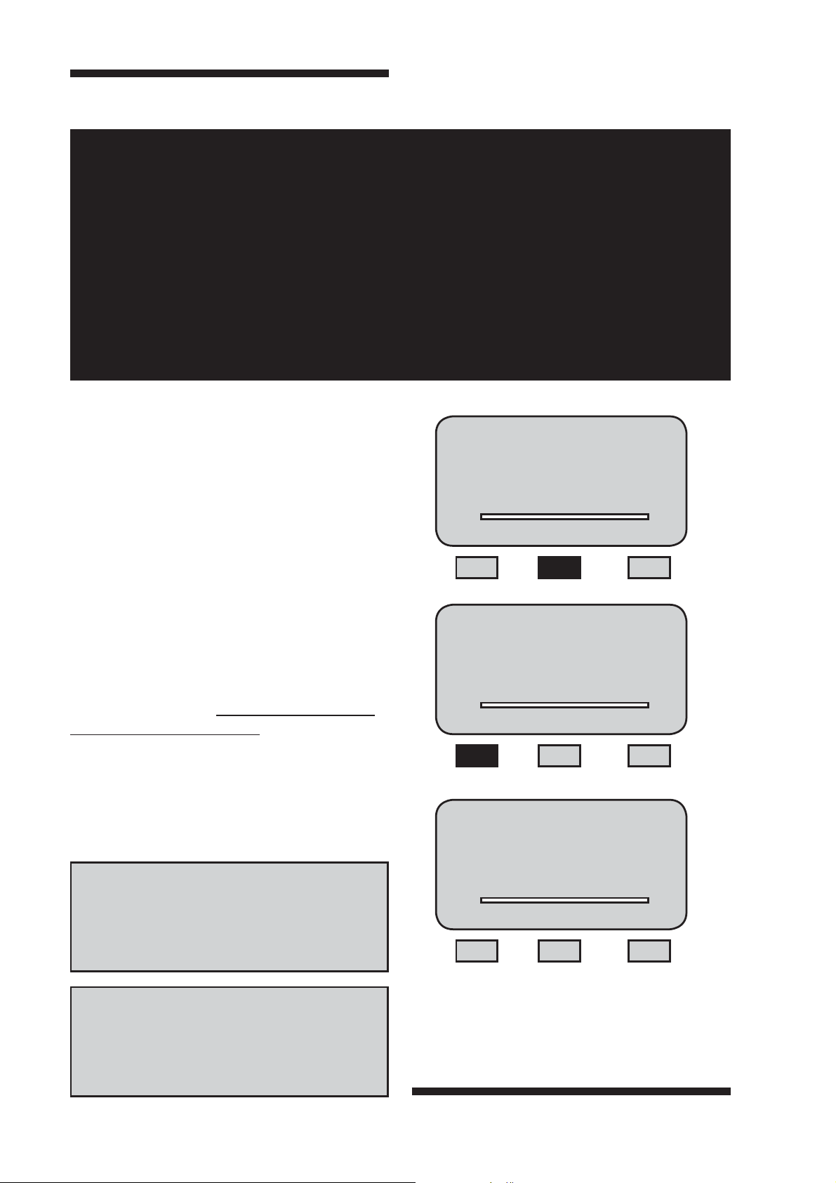
When the Title Display is shown, press the F2 key and
then the F1 key.
The gauge is now in Service Mode. Select ENTER to
begin the calibration procedure.
HELP
You must complete the entire calibration procedure in
order for the new calibration to take effect.
Model DFS-100
Rev. No. 1.00
Rev Date dd/mm/yyyy
Chatillon
www.chatillon.com
T
Gauge Service
Calibrate
>
Diagnostics
T
DIAG
C
C
HELP
You may abort the calibration routine at any time by
pressing the HOME key.
www.chatillon.com chatillon.fl -lar@ametek.com
- 2 -
Rev April 2006
Calibrating Your Gauge
Calibrating Your Gauge
Gauge calibration should be performed by an
authorized Chatillon Distributor or by AMETEK if you
require a Certifi cate of Calibration.
You may calibrate the gauge or verify the gauge calibration following this Gauge Calibration procedure.
At the Gauge Service main menu, select Calibrate.
Select Enter.
Gauge Service
Calibrate
>
Diagnostics
T
C
DIAG
About DFS Series Calibration
The DFS Series gauge requires a two point calibration
in both Compression and Tension directions. Masses
should be used that are CLASS 5 or better per ASTM
E617. Masses should be calibrated to local gravity.
Select Gauge Model
Your DFS Series gauge will automatically scale itself
based on the calibration and the gauge model selected.
You must specify the Gauge Model prior to performing
the calibration so the scaling is accurate.
Select F1 (Change) until the display indicates the
gauge model you are calibrating. The gauge model is
equivalent to the load capacity of the gauge in LBF. The
available models are:
DFS-250G
DFS-002
DFS-010
DFS-025
DFS-050
DFS-100
DFS-200
DFS-500
DFS-1000 (Not used with integral loadcell models)
Select Gauge Model
DFS-050
Enter to select
T
Change Keep
C
Select F3 (Keep) or ENTER to accept the displayed
gauge mode.
- 3 -
www.chatillon.comchatillon.fl -lar@ametek.com

Calibrating Your Gauge
Rev April 2006
Select Calibration UNITS
You may calibrate the gauge in the Units that correspond
to your calibration masses. The default calibration unit
is LBF. To change calibration units, press the UNITS key
until the displayed units correspond to your calibration
mass units.
Select
Calibrate Units &
Midpoint Calib. 50%
0.000
T
Back Proceed Flip
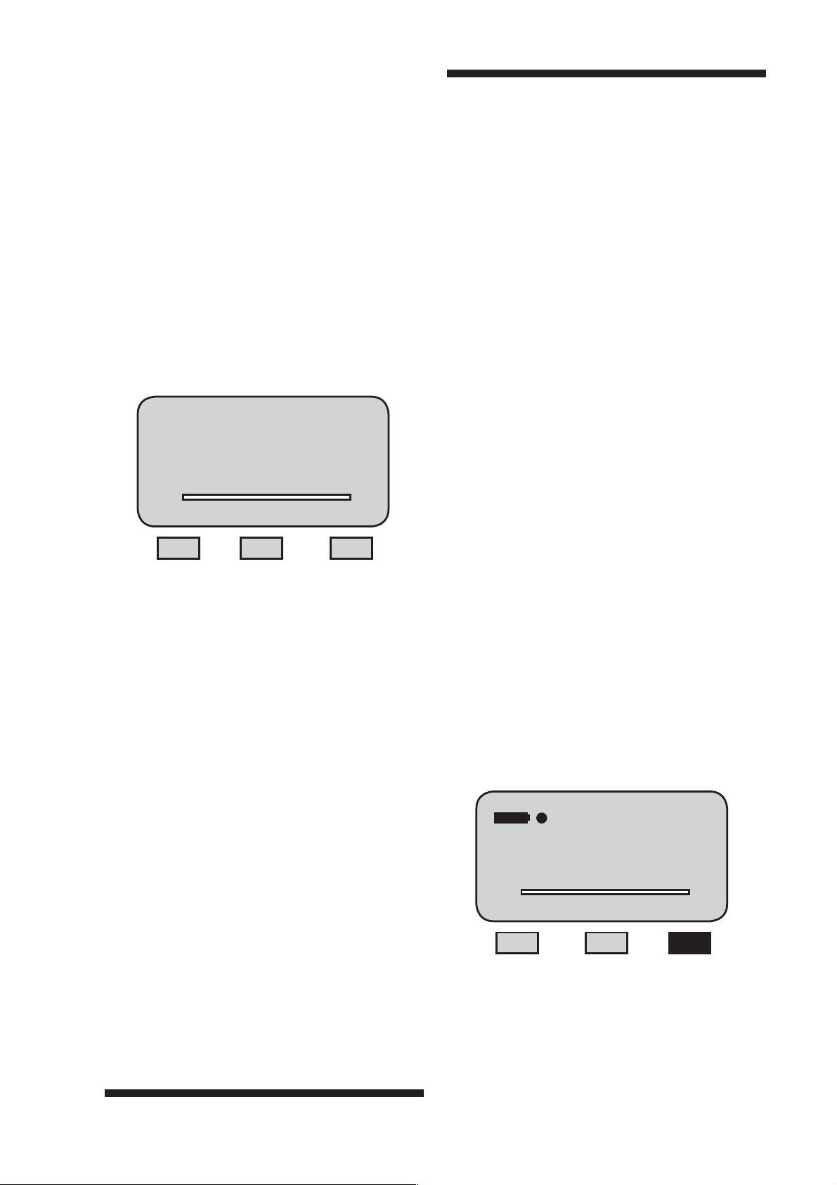
Select Calibration Midpoint Value
You may calibrate the gauge’s midpoint value as either
50% or 40% depending on your weight set or standards
used for your calibration. Use the RIGHT navigation key
to select a 50% midpoint. Use the LEFT navigation key
to select a 40% midpoint. Press F2 (Proceed).
LBF
C
Attach Gauge to FixtureCompression
Attach your gauge to your testing/calibration fi xture,
making sure that the gauge is secure and free of movement. The gauge should be positioned so that you
can apply your compression masses fi rst (the gauge is
positioned so that the load sensor is at the top and the
display is at the bottom- gauge is upside down). Affi x a
compression platen to the loadcell shaft.
,
,
40% Midpoint
50% Midpoint
,
,
Stablize the Gauge
You must stablize the gauge by placing the gauge in
a “horizontal position”. Lay the gauge fl at and ensure
that no load is being applied to the load sensor. This
minimizes any gravitational forces that can be applied to
the load sensor. Press F2 (Proceed).
Place Gauge or Load
Sensor in Horizontal
Position
0.000
T
Back Proceed Flip
LBF
C
Place Gauge or Load
Sensor in Compression
Mode, Exercise 3 times
0.000
T
Back Proceed Flip
“Flip” Display
Depending on your calibration fi xture setup, it may be
advantageous to “fl ip” the display so that compression
calibration text on your gauge is not displayed “upside
down”. Select the F3 (FLIP) key at any time to change
the display orientation 180-degrees.
Exercise Loadcell
You must exercise the loadcell prior to calibration. Place
a load equal to the gauge capacity on your gauge’s
platen, hold for 5 seconds and remove the load. Do this
procedure three times in succession. This minimizes
hysteresis in the loadcell prior to calibration. Press F2
(Proceed).
LBF
C
www.chatillon.com chatillon.fl -lar@ametek.com
- 4 -

Rev April 2006
Calibrating Your Gauge
Apply Zero Compression Load
Remove all weights from the compression platen affi xed
to the gauge. Do NOT remove the platen. Press F2
(Proceed).
Remove all Weight, but
Leave Compression
Fixture Attached
0.000
T
LBF
C
Back Proceed Flip
Apply Mid-Scale Compression Load
Carefully, apply your calibration masses to the compression platen that equal the gauge’s mid-scale capacity.
Note that the capacity is listed. This capacity was based
on the GAUGE MODEL you specifi ed at the start of the
Calibration Procedure and the MIDPOINT (40% or 50%).
Error Checking
The DFS Series gauge features automatic error checking in the calibration routine.
If the the gauge senses that the Mid-Scale Compression
Load applied is not what the Gauge Model is supposed
to be, the gauge will display an error message. If the
capacity listed is incorrect, you have incorrectly specifi ed
the Gauge Model. Return to the start of calibration and
select the correct gauge model or apply the expected full
scale compression load.
Calibration Error
Proceed to Retry
100LBF
T
60.0
LBF
C
Back Proceed Flip
Add Mid
Compression Load
25.0LBF
0.000
T
LBF
C
Back Proceed Flip
Allow the mid-scale compression load to stabilize.
Leave this load applied for 5 seconds and make sure not
to disturb the load that is being applied. Nothing should
come in contact with the compression load while it lays
on the compression platen.
Take care when applying individual masses if you are
stacking masses to equal the load capacity. Do NOT
drop masses. Place individual masses on the compression platen slowly until the total mass applied equals the
gauge capacity.
If you do not correct this error, the gauge will return you
to Prepare for Compression Calibration. You will not be
able to continue the calibration procedure.
When compression load is applied, Press F2 (Proceed).
- 5 -
www.chatillon.comchatillon.fl -lar@ametek.com

Calibrating Your Gauge
Rev April 2006
Apply Full Scale Compression Load
Carefully, apply your calibration masses to the compression platen that equal the gauge’s full scale capacity.
Note that the capacity is listed. This capacity was based
on the GAUGE MODEL you specifi ed at the start of the
Calibration Procedure.
Add Full Scale
Compression Load
50.0LBF
25.000
T
LBF
C
Back Proceed Flip
Allow the full scale compression load to stabilize. Leave
this load applied for 5 seconds and make sure not to
disturb the load that is being applied. Nothing should
come in contact with the compression load while it lays
on the compression platen.
Zero Verifi cation
Verify the gauge zero by carefully removing the masses
from the compression fi xture. Do NOT remove the
tension fi xture. Remove the masses only. Press F2
(Proceed).
HELP
The Zero reading must be within 0.5% of original
Zero point.
Remove Full Scale
Load for Zero
Verifi cation
50.000
T
LBF
C
Back Proceed Flip
Take care when applying individual masses if you are
stacking masses to equal the load capacity. Do NOT
drop masses. Place individual masses on the compression platen slowly until the total mass applied equals the
gauge capacity.
When full compression load is applied, Press F2
(Proceed).
Verify Compression Calibration
Apply incremental weights used for your calibration and
compare your readings to ensure that your compression
results are within the specifi cation.
If your measured results are not within specifi cation,
repeat the Compression Calibration procedure.
If your measured results are within specifi cation, you
may proceed to the Tension Calibration. Select F2
(Proceed).
Verify Compression
Calibration
0.000
LBF
T
C
Back Proceed Flip
www.chatillon.com chatillon.fl -lar@ametek.com
- 6 -

Rev April 2006
Calibrating Your Gauge
Attach Gauge to Fixture- Tension
Attach your gauge to your testing/calibration fi xture,
making sure that the gauge is secure and free of movement. The gauge should be positioned so that you can
apply your tension masses. Affi x a hook or fi xture for applying tension to the loadcell shaft. Press F2 (Proceed).
Apply Zero Tension Load
Remove all weights from the tension fi xture affi xed
to the gauge. Do NOT remove the fi xture. Press F2
(Proceed).
Remove all Weight, but
Leave Tension
Fixture Attached
0.000
T
LBF
C
Back Proceed Flip
Apply Mid-Scale Tension Load
Carefully, apply your calibration masses to the tension
fi xture that equal the gauge’s mid-scale capacity. Note
that the capacity is listed. This capacity was based on
the GAUGE MODEL you specifi ed at the start of the
Calibration Procedure and the MIDPOINT (40% or 50%).
Place Gauge or Load
Sensor in Tension
Mode, Exercise 3 times
0.000
T
LBF
C
Back Proceed Flip
“Flip” Display
Depending on your calibration fi xture setup, it may
be advantageous to “fl ip” the display so that tension
calibration text on your gauge is not displayed “upside
down”. Select the F1 (FLIP) key to change the display
orientation.
Exercise Loadcell
You must exercise the loadcell prior to calibration. Place
a load equal to the gauge capacity on your gauge’s
platen, hold for 5 seconds and remove the load. Do this
procedure three times in succession. This minimizes
hysteresis in loadcell prior to calibration. Press F2
(Proceed).
Add Mid
Tension Load
25.0LBF
0.000
T
LBF
C
Back Proceed Flip
Allow the mid-scale tension load to stabilize. Leave this
load applied for 5 seconds and make sure not to disturb
the load that is being applied. Nothing should come
in contact with the tension load while it hangs from the
tension fi xture.
Take care when applying individual masses if you are
stacking masses to equal the load capacity. Do NOT
drop masses. Place individual masses on your fi xture
slowly until the total mass applied equals the gauge
capacity. Press F2 (Proceed).
- 7 -
www.chatillon.comchatillon.fl -lar@ametek.com

Calibrating Your Gauge
Rev April 2006
Apply Full Scale Tension Load
Carefully, apply your calibration masses to the tension
fi xture that equal the gauge’s full scale capacity. Note
that the capacity is listed. This capacity was based on
the GAUGE MODEL you specifi ed at the start of the
Calibration Procedure.
Add Full Scale
Tension Load
50.0LBF
-25.000
T
LBF
C
Back Proceed Flip
Allow the full scale tension load to stabilize. Leave this
load applied for 5 seconds and make sure not to disturb
the load that is being applied. Nothing should come
in contact with the tension load while it hangs from the
tension fi xture.
Zero Verifi cation
Verify the gauge zero by carefully removing the masses
from the tension fi xture. Do NOT remove the tension
fi xture. Remove the masses only. Press F2 (Proceed).
HELP
The Zero reading must be within 0.5% of original
Zero point.
Remove Full Scale
Load for Zero
Verifi cation
-50.000
T
LBF
C
Back Proceed Flip
Take care when applying individual masses if you are
stacking masses to equal the load capacity. Do NOT
drop masses. Place individual masses on your fi xture
slowly until the total mass applied equals the gauge
capacity. Press F2 (Proceed).
Verify Tension Calibration
Apply incremental weights used for your calibration
and compare your readings to ensure that your tension
results are within the specifi cation.
If your measured results are not within specifi cation,
repeat the Tension Calibration procedure.
If your measured results are within specifi cation, you
may proceed to Calibrating analog output. Select F2
(Proceed).
Verify Tension
Calibration
0.000
LBF
T
C
Back Proceed Flip
www.chatillon.com chatillon.fl -lar@ametek.com
- 8 -

Rev April 2006
Calibrating Your Gauge
Calibrating the Analog Output
Calibrate the analog output of your DFS Gauge by
connecting the gauge to a certifi ed digital voltmeter. Use
cable NC000653 to connect the gauge to the voltmeter.
Remove all weight from the gauge. Press the ZERO
key.
Press the F2 (Proceed) key once. The gauge is zeroed.
Use the UP and DOWN key on the navigation pod to
zero the analog output voltage. The voltmeter should
read 0.000 (+0.002) Vdc. Use the UP key to increase
the voltage reading or the DOWN key to decrease the
voltage reading. When the voltmeter displays 0.000,
press F2 (Proceed).
Voltmeter
Remove Load and
Press Zero
0.000
T
LBF
Back Proceed Flip
Use Up or Down
arrows to Zero
analog voltage
0.000
T
LBF
Back Proceed Flip
C
C
DFS
Double Banana Jack Cable (p/n NC000653)
Save Calibration
After verifying your tension results and calibrating the
analog output (DFS), save your calibration points by
selecting F2 (Save).
The gauge will give an audible “BEEP” indicating that
your calibration is saved.
The gauge will return to the main Service Menu display.
Select HOME key to begin normal operation.
Save New Calibration
0.000
T
LBF
C
Back Save
Gauge Service
Calibrate
>
Diagnostics
T
C
DIAG
- 9 -
www.chatillon.comchatillon.fl -lar@ametek.com
 Loading...