

Page 1
i
MVE TS Controller (Touch Screen)
Quick Reference
G
uide
Page 2

MVE TS Quick Reference Guide
1 — 21081123 A
Table of Contents
Product Identification
Display / Control Panel . . . . . . . . . . . . . . . . . . . . . . . . . . . . . . . . . . . . . . . . . . . . . . . . . 2
Bottom Panel / Electrical / Physical Connections . . . . . . . . . . . . . . . . . . . . . . . . . . . . . 3
Dewar Plumbing Connections . . . . . . . . . . . . . . . . . . . . . . . . . . . . . . . . . . . . . . . . . . . . . . 4
Adjusting Temperature Alarm Settings . . . . . . . . . . . . . . . . . . . . . . . . . . . . . . . . . . . . . . . . 5
Adjusting Inlet Temperature Settings . . . . . . . . . . . . . . . . . . . . . . . . . . . . . . . . . . . . . . . . . 8
Adjusting Liquid Level & Liquid Level Alarm Settings. . . . . . . . . . . . . . . . . . . . . . . . . . . . . 12
High Level Alarm Setting
High Level Setting
Low Level Setting
Low Level Alarm Setting
Adjusting Display and Output Settings . . . . . . . . . . . . . . . . . . . . . . . . . . . . . . . . . . . . . . 15
Password and Security Setup . . . . . . . . . . . . . . . . . . . . . . . . . . . . . . . . . . . . . . . . . . . . . 18
Alarms and Definitions . . . . . . . . . . . . . . . . . . . . . . . . . . . . . . . . . . . . . . . . . . . . . . . . . . . 21
Contact Information . . . . . . . . . . . . . . . . . . . . . . . . . . . . . . . . . . . . . . . . . . . . . . . . . . . . . 21
Page 3

MVE TS Quick Reference Guide
2 — 21081123 A
3
4
1
5
6
Table 1: Front Panel Identification
Display
6” touchscreen, backlight
Freezer Status
Displays “IDLE”, “BYPASSING”, or “FILLING” based on the
current freezer status
START FILL
Key
Used to manually initiate a fill
FOG CLEAR
To clear fog when opening the lid or to perform a manual fill.
Momentary circuit
STOP FILL
Key
Used to manually terminate a fill – Disables Auto Fill for 30
minutes
ALARM
MUTE Key
Used to silence the audible alarm. Will reset the latching alarm
once it has been corrected
SETUP Key
Used to access Setup Menus and parameters
Trend Graph
Adjustable graph of historical level and temperature data.
Visual X,Y Graph parameters adjustable in days, temperature,
and level ranges.
Page 4

MVE TS Quick Reference Guide
3 — 21081123 A
.
1
Temp A Port
Connection for Temp A probe
2
Temp B Port
Connection for Temp B probe
3
Serial Number Barcode
Chart TS serial number written below barcode
4
30 VDC Power Input
Main power supply connection
5
Serial Port
RJ-45 connection for Serial/COM
6
Ethernet Port
Ethernet connection for networking
7
Global/Discrete Alarm
Contacts
15 pin alarm output. Output connection for the remote
monitoring of alarm conditions.
8
Wire Harness Connection
12-pin wire harness connection to plumbing assembly, lid
switch, and battery backup
9
Level Connection
Level signal input. Clear, vinyl tube connects to hose barb
1 2 3 4 5
6 7 8
9
Page 5
4 — 21081123 A
MVE TS Quick Reference Guide
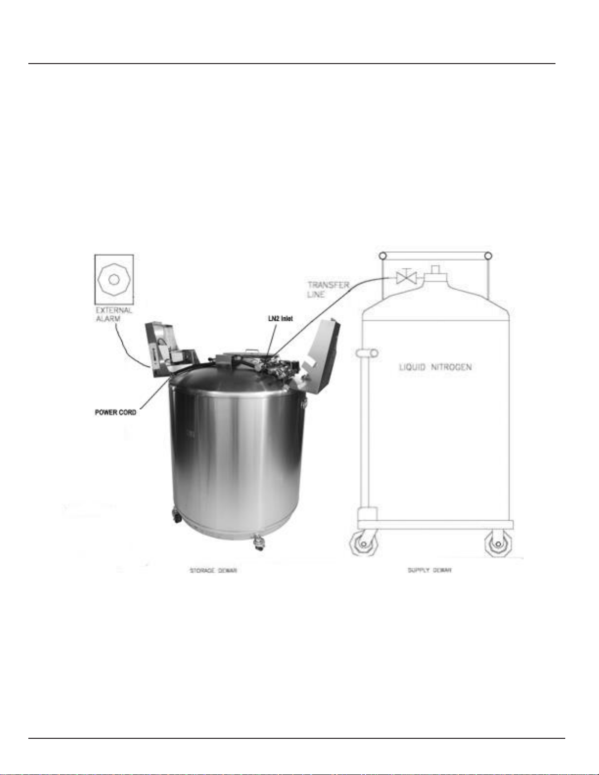
Dewar Plumbing Connections
Connect a transfer line (included with freezer) from an LN2 supply tank to the fill connection at the rear of the
freezer. Optimum supply tank pressure is 22 to 35 psi (1.5 to 2.4 bar). Although the plumbing assembly has a
50 psi (3.45 bar) pressure relief device, it is recommended that the supply tank be pressurized below 35 psi
(2.4 bar) to reduce the LN2 “flash-off” rate during filling and to maximize the cryogenic valve life. The supply
line can be insulated to minimize LN2 transfer losses. After the transfer hose is securely coupled to the freezer
and supply tank, ensure all connections are leak free by opening the valve of the LN2 supply tank and apply a
soap and water solution to each field joint. You should not see bubbles forming at any joint. Wipe away excess
soap and water when finished. Before removing the transfer hose, ensure the LN2 supply tank valve is closed.
Slowly and carefully loosen the transfer hose connection to vent any remaining pressure in the line before
disconnecting the hose.
Page 6

5 — 21081123 A
MVE TS Quick Reference Guide
A & B and Inlet (Hot Gas Bypass)
The following section describes how to adjust temperature alarm settings. At any time
during the following procedure, the user may exit the menu by pressing the “EXIT” button
to return to the “monitor” display mode. After 60 seconds of inactivity, the controller will
automatically return to the “monitor” display mode.
NOTE: Security Level 2 or higher is required to adjust temperature settings (see
“Password and Security Setup” section for details).
To exit any menu screen and return to the previous menu, press “<” key.
1. Press “Setup”
Controller will prompt for a password. Type in the password using the number pad that appears and
press “Enter”.
2. Press “Temperature Settings”
Page 7

6 — 21081123 A
MVE TS Quick Reference Guide
3. Press “Temperature A Settings”
NOTE: To access Temperature B Settings select “Temperature B Settings” instead.
4. Press “ENABLED” or “DISABLED” next to “Temperature Probe A”
This will enable or disable the selected temperature probe. Pressing “ENABLED” will change the
probe status to “DISABLED” and pressing “DISABLED” will change the probe status to “ENABLED”.
Page 8
7 — 21081123 A
MVE TS Quick Reference Guide
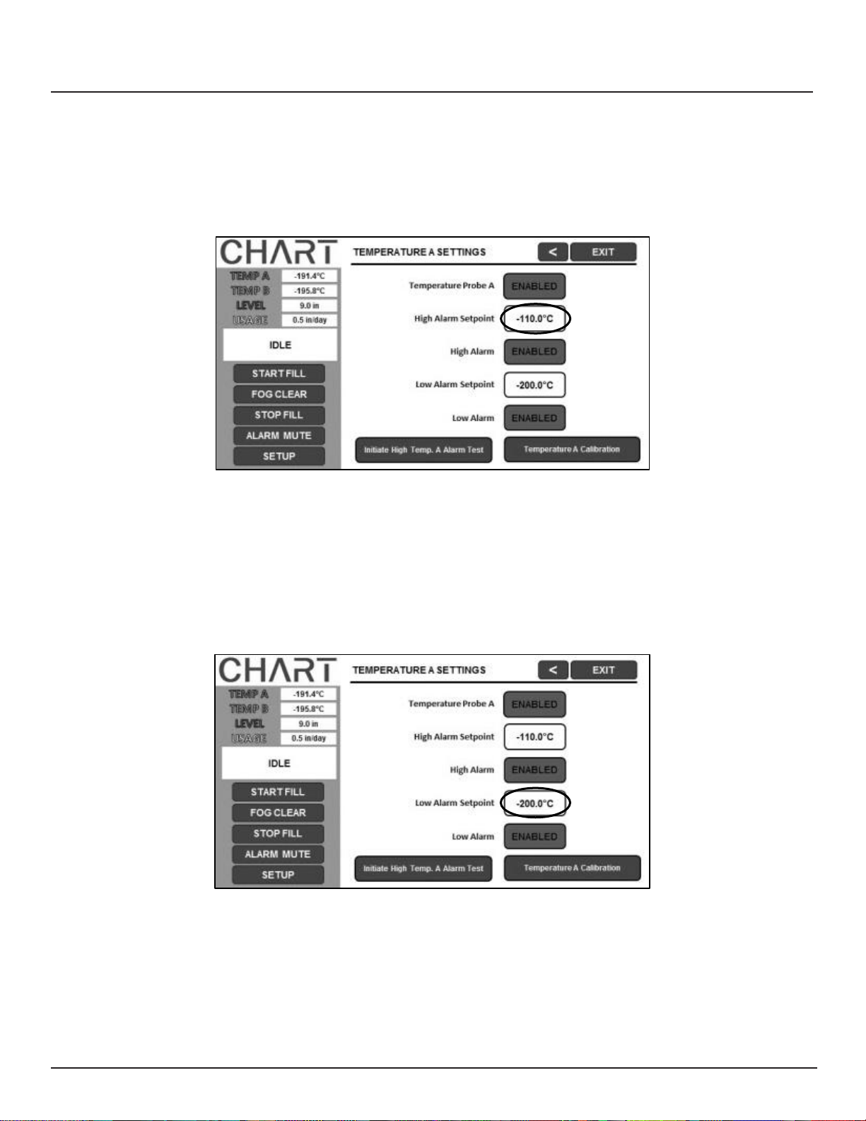
5. Press the value displayed next to “High Alarm Setpoint”
The number pad will be displayed once the value to be adjusted is selected. Type in a new value for
the High Alarm Setpoint using the number pad that appears on screen and then press “Enter” to save
the new value. Be sure to include “-“ when entering negative values.
6. Press the value displayed next to “Low Alarm Setpoint”
The number pad will be displayed once the value to be adjusted is selected. Type in a new value for
the Low Alarm Setpoint using the number pad that appears on screen and then press “Enter” to save
the new value. Be sure to include “-“ when entering negative values.
Page 9
8 — 21081123 A
MVE TS Quick Reference Guide
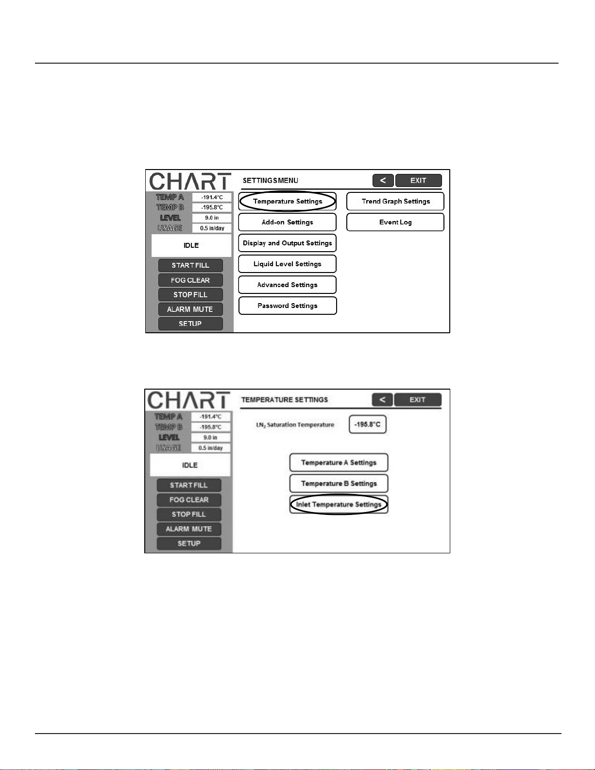
Adjusting Inlet Temperature Settings (Hot Gas Bypass)
1. Press “Temperature Settings”
2. Press “Inlet Temperature Menus”
Page 10
9 — 21081123 A
MVE TS Quick Reference Guide
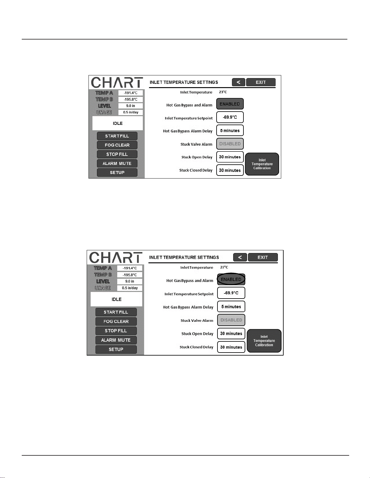
3. The current Hot Gas Bypass settings will be displayed
The current inlet temperature is displayed, along with the hot gas bypass setpoints.
4. Press “ENABLED” or “DISABLED” next to “Hot Gas Bypass and Alarm”
This will enable or disable the Hot Gas Bypass feature. Pressing “ENABLED” will change the hot gas
bypass status to “DISABLED” and pressing “DISABLED” will change the hot gas bypass status to
“ENABLED”.
Page 11
10 — 21081123 A
MVE TS Quick Reference Guide
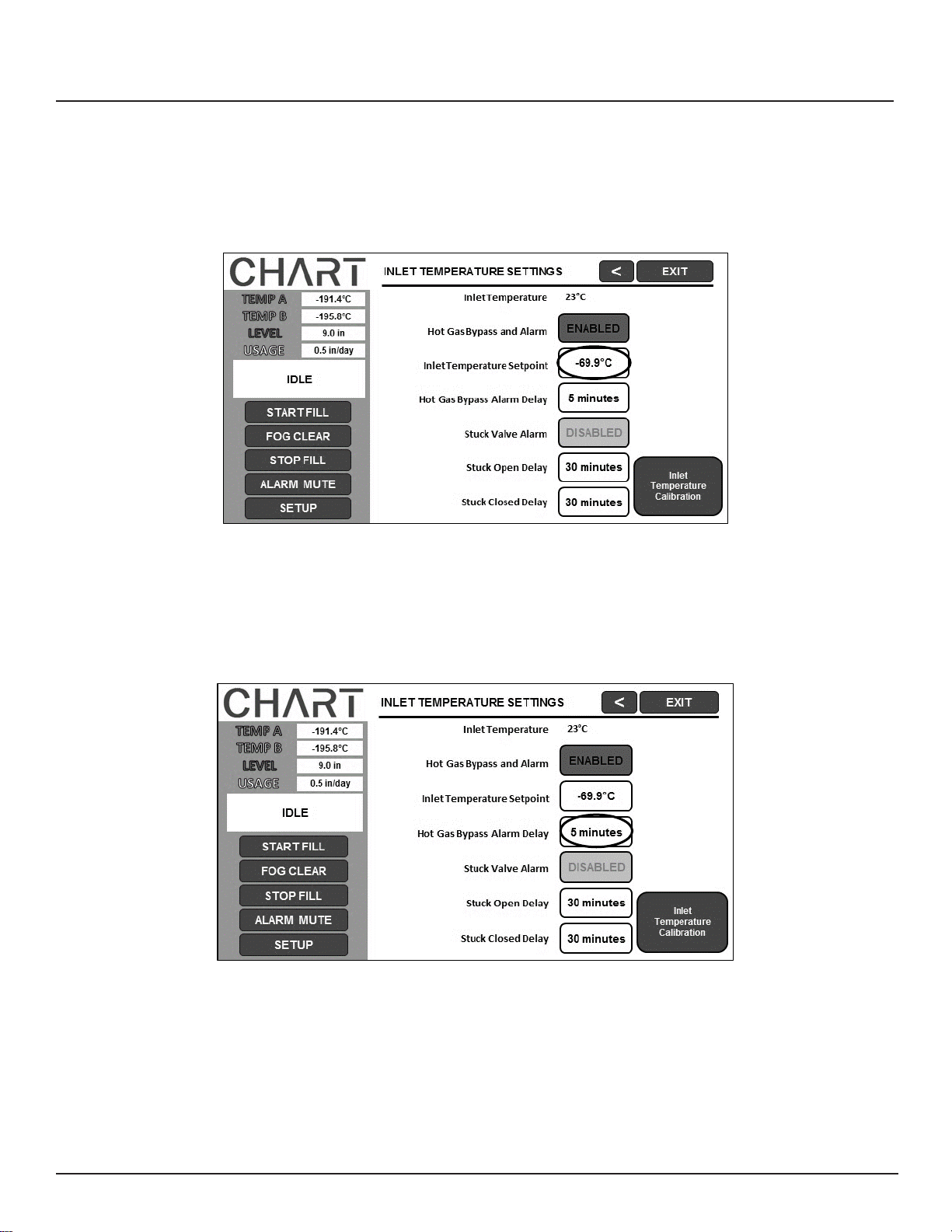
5. Press the value displayed next to “Inlet Temperature Setpoint”
The number pad will be displayed once the value to be adjusted is selected. Type in a new value for the inlet temperature setpoint (if desired) using the number pad that appears on screen and then press “Enter” to save the new value.
6. Press the value displayed next to “Hot Gas Bypass Alarm Delay”
The number pad will be displayed once the value to be adjusted is selected. Type in a new value for the hot gas bypass alarm delay (if desired) using the number pad that appears on screen and then press “Enter” to save the new value.
Page 12
11 — 21081123 A
MVE TS Quick Reference Guide
Adjusting Liquid Level & Liquid Level Alarm Settings
The following section describes how to adjust liquid nitrogen level settings and the
high/low level alarms. NOTE: Security Level 2 or higher is required to adjust the Level
and Level Alarm settings (See “Password and Security Setup” section for details).
NOTE: To exit any menu screen and return to the previous menu press “<” key.
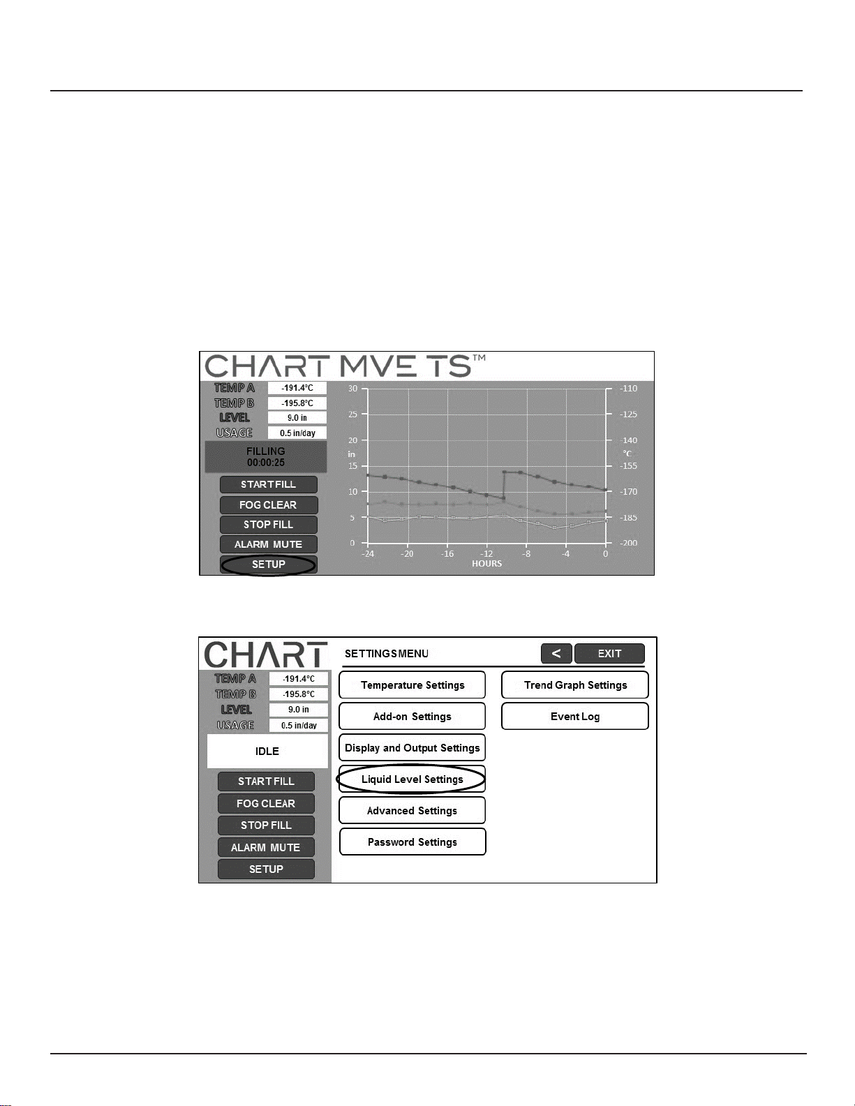
1. Press “Setup”
Controller will prompt for a password. Type in the password using the number pad that appears and
press “Enter”.
2. Press “Liquid Level Settings”
Page 13
12 — 21081123 A
MVE TS Quick Reference Guide
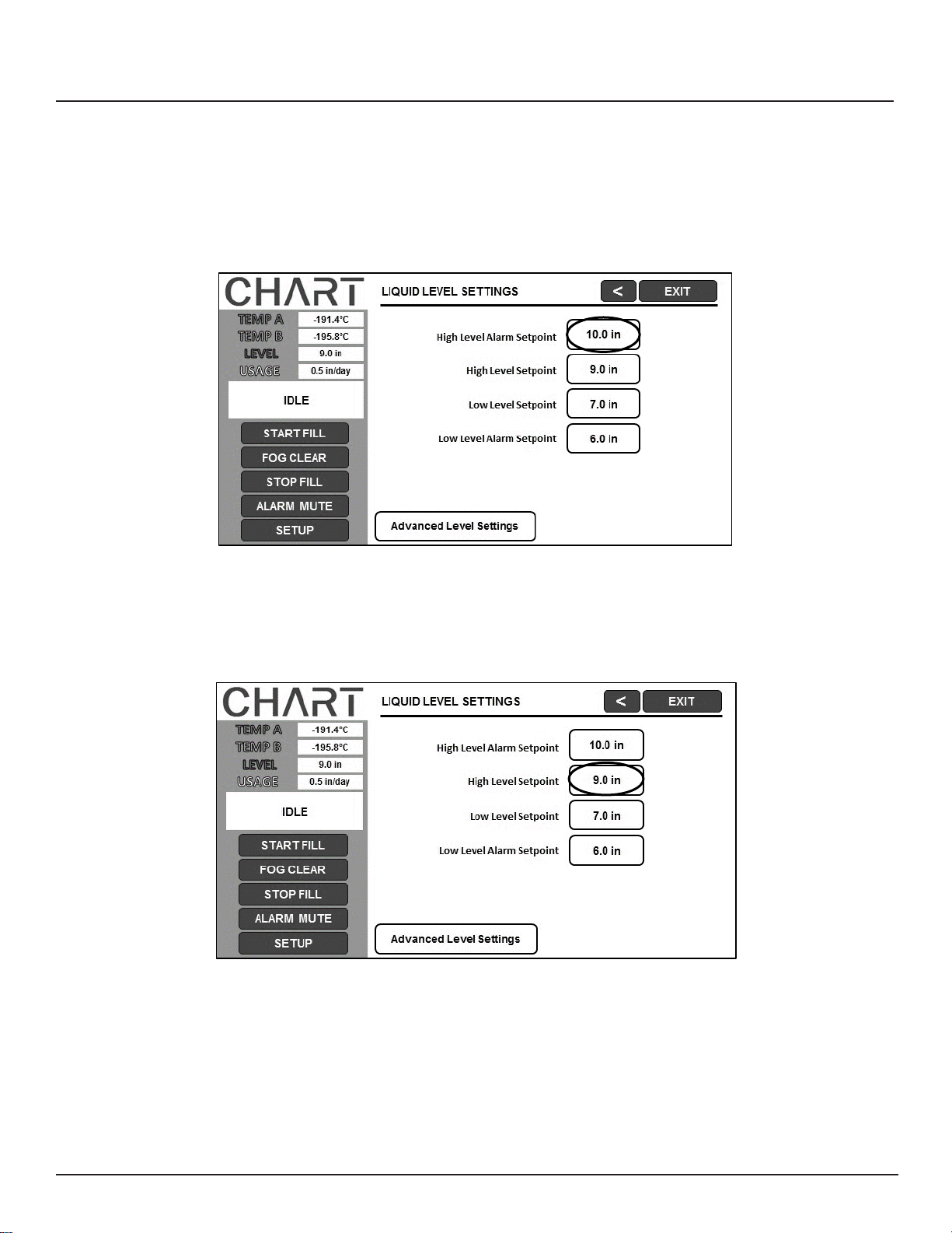
3. Press the value displayed next to “High Level Alarm Setpoint”
The number pad will be displayed once the value to be adjusted is selected. Type in a new value for
the High Level Alarm Setpoint using the number pad that appears on screen and then press “Enter”
to save the new value.
4. Press the value displayed next to “High Level Setpoint”
The number pad will be displayed once the value to be adjusted is selected. Type in a new value for
the High Level Setpoint using the number pad that appears on screen and then press “Enter” to save
the new value.
Page 14
13 — 21081123 A
MVE TS Quick Reference Guide
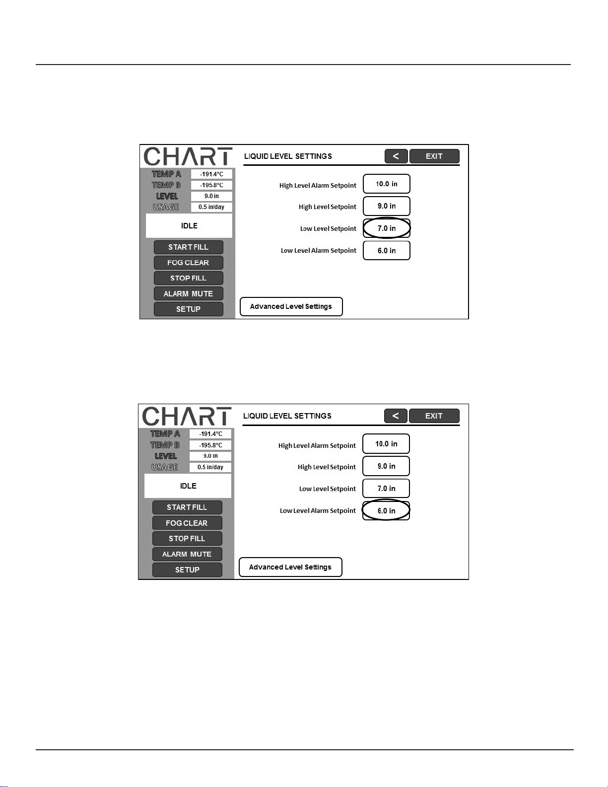
5. Press the value displayed next to “Low Level Setpoint”
The number pad will be displayed once the value to be adjusted is selected. Type in a new value for the Low Level Setpoint using the number pad that appears on screen and then press “Enter” to save the new value.
6. Press the value displayed next to “Low Level Alarm Setpoint”
The number pad will be displayed once the value to be adjusted is selected. Type in a new value for the Low
Level Alarm Setpoint using the number pad that appears on screen and then press “Enter” to save the new
value.
Adjusting Display and Output Settings
Page 15
14 — 21081123 A
MVE TS Quick Reference Guide
The units of measurement displayed by the MVE TS may be adjusted to
accommodate the needs of the user. Temperature measurement may be displayed in
Kelvin (K), degrees Celsius (°C), or degrees Fahrenheit (°F). The amount of liquid
nitrogen in the freezer may be displayed in inches (in), millimeters (mm). In addition, the
amount of liquid nitrogen consumed by the freezer (liquid usage) may be shown on the
display.
NOTE: Security Level 1 is required to adjust the display and output settings (See
“Password and Security Setup” section for details).
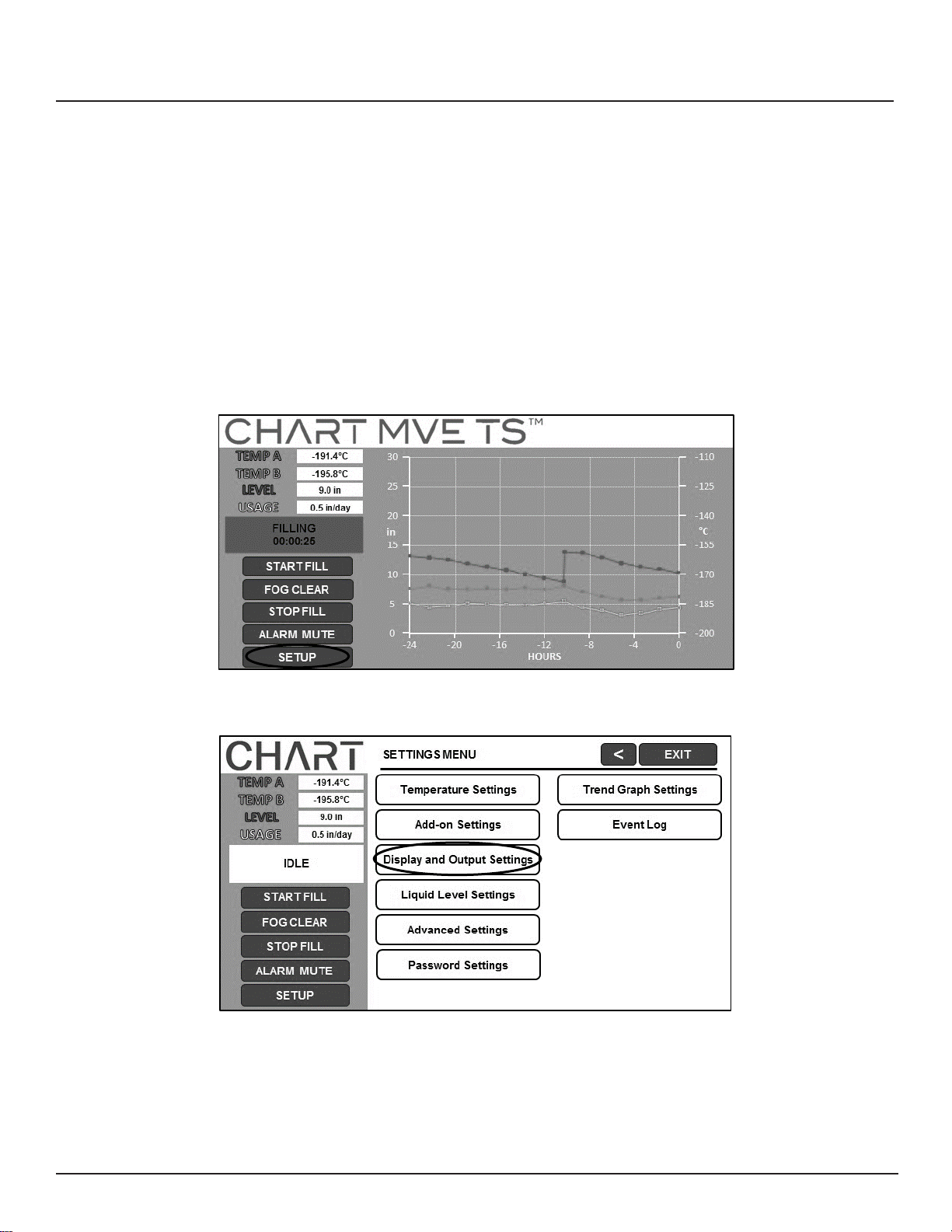
1. Press “Setup”
Controller will prompt for a password. Type in the password using the number pad that appears and press “Enter”.
2. Press “Display and Output Settings”
Page 16
15 — 21081123 A
MVE TS Quick Reference Guide
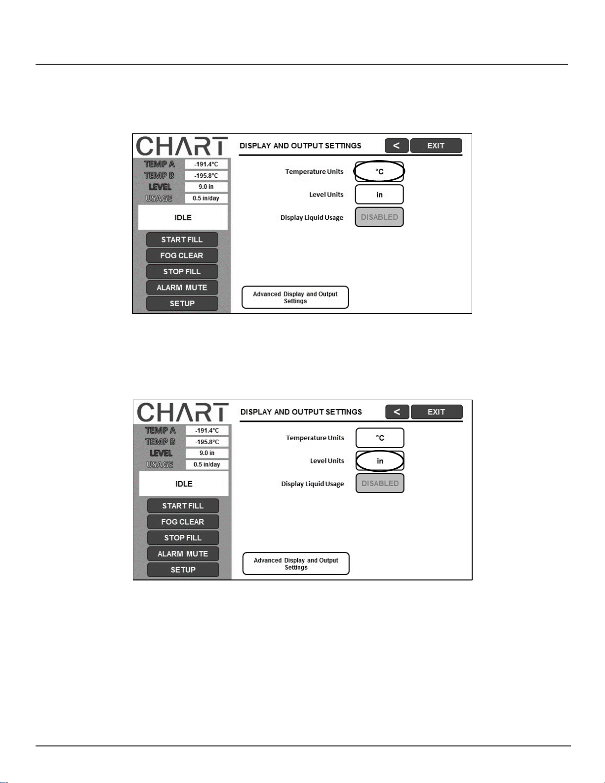
3. Press the units displayed next to “Temperature Units”
Press the “°C”, “°F”, or the “K” option for “Temperature Units”.
4. Press the units displayed next to “Level Units”
Press the “in” or “mm” option for “Level Units”.
Page 17
16 — 21081123 A
MVE TS Quick Reference Guide
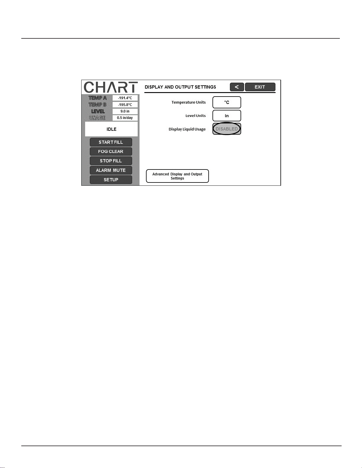
5. Press “ENABLED” or “DISABLED” next to “Display Liquid Usage”
This will enable or disable the liquid usage feature. Pressing “ENABLED” will change the liquid usage
status to “DISABLED” and pressing “DISABLED” will change the liquid usage status to “ENABLED”.
Page 18

17 — 21081123 A
MVE TS Quick Reference Guide
Password and Security Setup
The MVE TS can store up to 10 different passwords. Each password can be assigned its own
security level ranging from Level 1 to Level 4. Table 3 below shows which settings can be
changed with each security level. A security level of 4 is required to adjust an y password.
The default (or “Global”) password for the MVE TS is “3456”. All parameters may be
adjusted by using this password. Record all passwords and security settings and store in a
safe place. NOTE: MVE recommends changing the global password, as it is common to all
units. If the global password has been forgotten, contact MVE Customer Service for details on
how to reset passwords.
Table 3: Security Levels and Definitions
FEATURE
LEVEL 1
LEVEL 2
LEVEL 3
LEVEL 4
Fill
Start X X X X
Fill
Stop X X X X
Alarm Mute
X X X X
Change
Display Units
X X X X
Temp
Settings
X X X
Level
Settings
X X X
T
ime/Date
X X X
Calibration
Probes
X X X
Change
Lang
uages
X X X
Hot Gas
Bypass Settings
X X X
OFAF
Setting
X X
Communication
Settings
X X
Programming
X X
Password Settings
X
Page 19
18 — 21081123 A
MVE TS Quick Reference Guide
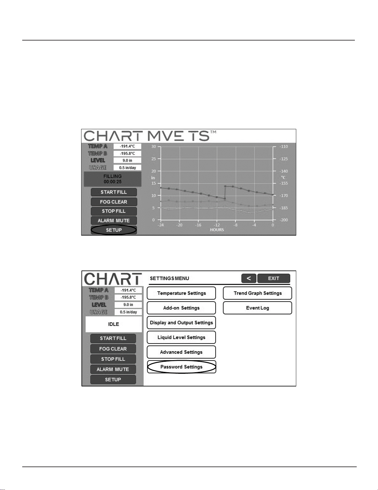
This section details how to enable / disable password entry mode as well as how to change and setup multilevel security passwords.
NOTE: Security Level 4 is required to setup or change passwords.
1. Press “Setup”
Controller will prompt for a password. Type in the password using the number pad that appears and press “Enter”.
2. Press “Password Settings”
Page 20
19 — 21081123 A
MVE TS Quick Reference Guide
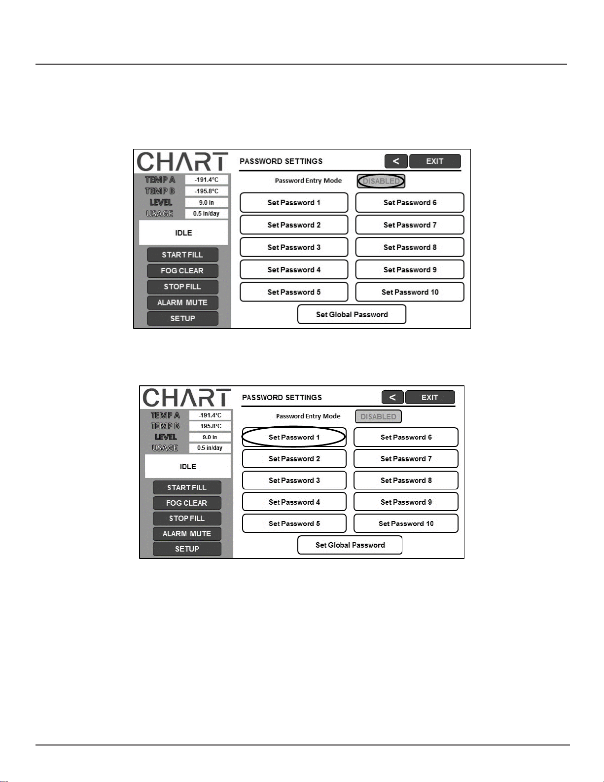
3. Press “ENABLED” or “DISABLED” next to “Password Entry Mode”
This will enable or disable the password entry mode. Pressing “ENABLED” will change the password entry mode to “DISABLED” and pressing “DISABLED” will change the password entry mode to “ENABLED”.
4. Press the desired password to setup or adjust.
5. Enter a new password and password level.
Page 21

20 — 21081123 A
MVE TS Quick Reference Guide
USA:
Phone:
1-800-482-2473
Europe:
Phone:
Fax:
1-888-932-2473
Fax:
+44 (0) 1344 429 224
Asia:
Phone:
+61 297 494333
Fax:
+61 297 494666
Alarms and Descriptions
Table 4: Alarms and Desciptions
Alarm Display
Description
High Temp A
The temperature of Probe A is above the user defined High Temperature
setting.
High Temp B
The temperature of Probe B is above the user defined High Temperature
setting.
Low Temp A
The temperature of Probe A is below the user defined Low Temperature
setting.
Low Temp B
The temperature of Probe B is below the user defined Low Temperature
setting.
High Level
The depth of LN2 inside the freezer is above the user defined High level setting.
Low Level
The depth of LN2 inside the freezer is below the user defined Low level setting.
Usage Warning
The consumption of LN2 has doubled.
Usage Alarm
The consumption of LN2 has increased by a factor of 5.
Fill Time
The amount of time required to complete a fill cycle exceeds the user defined
Fill Time setting.
Bypass Time
The amount of time required to complete a bypass cycle exceeds the user defined
Bypass Time setting.
Temp A Calibration
The temperature of Probe A is lower than absolute zero.
Temp B Calibration
The temperature of Probe B is lower than absolute zero.
Bypass Calibration
The temperature of the Bypass Probe is lower than absolute zero.
Low Battery
The voltage of the back up batteries has dropped below 21 volts.
Power Failure
The primary power has been disconnected for at least 30 minutes.
Lid Open
The lid on the freezer has been open longer than the user specified time.
Communication Loss
The controller has lost communications with the display.
If any alarms occur, contact your authorized
MVE Distributor or customer / technical service.
Customer/Technical Service:
Page 22

21 — 21081123 A
MVE TS Quick Reference Guide
NOTES
Page 23

2200 Airport Industrial Dr., Ste 500
Ball Ground, GA 30107, U.S.A.
www.chartbiomed.com
Unit 2, Maxdata Centre
Downmill Road
Bracknell
Berks RG12 1QS, United Kingdom
21081123 rev A
Copyright © 2016 Chart Industries
Chart Inc. reserves the right to discontinue its products, or change the prices, materials, equipment, quality,
descriptions, specifications and/or processes to its products at any time without prior notice and with no further
obligation or consequence. All rights not expressly stated herein are reserved by us, as applicable.
 Loading...