

Page 1

Product Manual
APPS-160
Designed and Built by:
Chart Inc.
407 7th Street NW
New Prague, MN 56071 USA
(800) 400-4683
Part Number 11929931 Rev. B
© 2014 Chart Inc.
Page 2

Page 3

Product Manual - APPS 160
Contents
Revision Log iv
Preface. . . . . . . . . . . . . . . . . . . . . . . . . . . . . . . . . . . . . . . . . . . . . . . . . . . . .1
General 1
Technical Features 1
Product Manual 1
Terms 1
Acronyms / Abbreviations 2
Safety . . . . . . . . . . . . . . . . . . . . . . . . . . . . . . . . . . . . . . . . . . . . . . . . . . . . .3
General 3
Nitrogen and Argon 4
Installation / Operation. . . . . . . . . . . . . . . . . . . . . . . . . . . . . . . . . . . . . . . . . . . .5
Installation 5
Start-Up 5
Operation 5
Adjustments 6
Operating Pressure 6
Liquid Nitrogen Level 6
Troubleshooting 7
iii
Specications . . . . . . . . . . . . . . . . . . . . . . . . . . . . . . . . . . . . . . . . . . . . . . . . .9
APPS 160 & APPS 160 (220V) 9
Service 10
Control Box Electrical Schematic 13
Page 4

Table of Contents Product Manual - APPS 160
iv
Revision Log
Revision Level Date Description
B 07/25/2014 Convert to new layout and combine with manual PN 13428250 for 220V
Page 5

Product Manual - APPS 160
Preface
1
General
The Adjustable Pressure Phase Separator (APPS 160) unit
is used to lower the saturation point of liquid nitrogen
Liquid nitrogen saturated at a high pressure ows into the
APPS 160 and exits at a much lower saturation pressure
and temperature Liquid nitrogen enters the APPS 160 unit
through an automatic solenoid valve and exits through a
one-inch vacuum insulated female bayonet A differential
pressure switch maintains the liquid level in the cylinder
The internal pressure of the cylinder is controlled by the
combination of a pressure switch connected to the solenoid
valve and a back-pressure regulator If the pressure exceeds
the set point of the back-pressure regulator, the pressure
switch activates a solenoid valve that rapidly vents the APPS
160 down to the desired working pressure
Technical Features
• Tighter pressure control for the lower pressure liquid
application
• Adjustable outlet pressure ranges
Product Manual
The APPS 160 Product Manual is designed to be used in
conjunction with APPS 160 provided by Chart If there are
any questions regarding the operation of this unit, contact
Chart’s Technical Service division at 1-800-400-4683.
This manual contains information regarding the safe
operation and handling of liquid nitrogen, argon and oxygen
with this unit It should be thoroughly read and understood
by anyone that operates the equipment
The safety requirements for operating the unit and handling
of extremely cold liquid products are shown in the Safety
section Use this safety section as a “Safety Checklist” each
time the equipment is being used
The Installation / Operation section includes information on
how to install the APPS 160, initial start-up and operation of
the unit and references any adjustments that may need to be
made
For information on identication of components, schematic
of the unit, electrical schematic, or service information see
the Specications section.
• Working capacity of 160 liters
• Bayonet outlet connection is standard
• Mufer to reduce noise levels (98 to 106 dB)
• Major components moved out of the frost area
• Intuitive ip toggle switch
• More accurate and reliable level gauge located out of the
frost area
• Allows low pressure liquid and high pressure gas from a
single storage vessel
• More precise pressure control on liquid use
• Mini-bulk storage for under-sized vacuum lines
• Low cost alternative to two bulk tanks
• Two operating pressure ranges available
• Stainless steel plumbing
Terms
Throughout this manual safety precautions will be designated
as follows:
Warning! Description of a condition that
can result in personal injury or
death.
Caution! Description of a condition that
can result in equipment or
component damage.
Note: A statement that contains information
that is important enough to emphasize or
repeat.
Page 6

Preface Product Manual - APPS 160
2
Acronyms / Abbreviations
The following acronyms / abbreviations are used throughout this manual:
APPS 160 Adjustable Pressure Phase Separator
dB Decibel
GPM Gallons per minute
Hz Hertz
MA WP Maximum Allowable Working Pressure
OD Outer Dimension
PN Part Number
PSI Pounds per Square Inch
PSIG Pounds per Square Inch (Gauge)
Page 7

Product Manual - APPS 160
Safety
General
3
Strict compliance with proper safety and handling practices
is necessary when using an APPS 160 unit We recommend
that all our customers re-emphasize safety and safe handling
practices to all their employees and customers While every
possible safety feature has been designed into the units and
safe operations are anticipated, it is essential that every user
of the APPS 160 unit carefully read all warnings listed in this
safety section and contained in the manual itself Periodic
review of this safety summary is recommended
Warning! INSTALLATION: The APPS 160
should be installed by a trained,
knowledgable technician. The
cryogenic piping connected
to the inlet and outlet must
be constructed of materials
suitable for cryogenic service
and properly protected from
possible over-pressure.
The electrical connections
to the control box should
be completed by a trained
technician per the wiring
schematic. The APPS 160
should be located on suitable,
level surface and be properly
fastened to prevent movement.
Warning! ASPHYZIATION HAZARD:
The venting nitrogen gas may
displace the available oxygen
in the area to the point where
the atmosphere is decient in
oxygen. The cold nitrogen vent
gas can collect in low areas,
increasing the potential risk.
When the APPS 160 is installed
indoors or in any area with poor
ventilation, the installation of
an oxygen monitor should be
considered.
The normal oxygen content of air is approximately 21%
Depletion of oxygen content in air, either by combustion
or by displacement with inert gas, is a potential hazard and
users should exercise suitable precautions
One aspect of this possible hazard is the response of humans
when exposed to an atmosphere containing only 8 to 12%
oxygen In this environment, unconsciousness can be
immediate with virtually no warning
When the oxygen content of air is reduced to about 15
to 16%, the ame of ordinary combustible materials,
including those commonly used as fuel for heat or light,
may be extinguished Somewhat below this concentration,
an individual breathing the air is mentally incapable of
diagnosing the situation because the onset of symptoms
such as sleepiness, fatigue, lassitude, loss of coordination,
errors in judgment and confusion can be masked by a state of
“euphoria,” leaving the victim with a false sense of security
and well being
Human exposure to atmosphere containing 12% or less
oxygen leads to rapid unconsciousness Unconsciousness can
occur so rapidly that the user is rendered essentially helpless
This can occur if the condition is reached by an immediate
change of environment, or through the gradual depletion of
oxygen
Most individuals working in or around oxygen decient
atmospheres rely on the “buddy system” for protection obviously the “buddy” is equally susceptible to asphyxiation
if he or she enters the area to assist the unconscious partner
unless equipped with a portable air supply Best protection
is obtainable by equipping all individuals with a portable
supply of respirable air Life lines are acceptable only if the
area is essentially free of obstructions and individuals can
assist one another without constraint
If an oxygen decient atmosphere is suspected or known to
exist:
1 Use the “buddy system ” Use more than one “buddy” if
necessary to move a fellow worker in an emergency
2 Both the worker and “buddy” should be equipped with
self-contained or airline breathing equipment
Warning! EXTREME TEMPERATURES:
Surfaces in contact with the
cryogenic liquid nitrogen or the
vent gas will become extremely
cold. These surfaces should not
be touched.
Page 8

Safety Product Manual - APPS 160
4
Warning! PRESSURIZED EQUIPMENT:
In normal operation the APPS
160 and the associated piping
will be pressurized. Before the
pressure vessel is serviced or
any plumbing components are
removed, all pressure must be
released.
Warning! ELECTRICAL EQUIPMENT: In
normal operation the APPS 160
has wiring that is powered with
120 volt AC power. In addition,
other wiring can be activated
automatically without notice.
Only knowledgeable technicians
should access or repair the
electrical wiring.
Nitrogen and Argon
Nitrogen and argon (inert gases) are simple asphyxiates
Neither gas will support or sustain life and can produce
immediate hazardous conditions through the displacement
of oxygen Under high pressure these gases may produce
narcosis even though an adequate oxygen supply sufcient
for life is present
Nitrogen and argon vapors in air dilute the concentration
of oxygen necessary to support or sustain life Inhalation
of high concentrations of these gases can cause anoxia,
resulting in dizziness, nausea, vomiting, or unconsciousness
and possibly death Individuals should be prohibited from
entering areas where the oxygen content is below 19%
unless equipped with a self-contained breathing apparatus
Unconsciousness and death may occur with virtually no
warning if the oxygen concentration is below approximately
8%. Contact with cold nitrogen or argon gas or liquid can
cause cryogenic (extreme low temperature) burns and freeze
body tissue
Persons suffering from lack of oxygen should be
immediately moved to areas with normal atmospheres
SELF-CONTAINED BREATHING APPARATUS MAY BE
REQUIRED TO PREVENT ASPHYXIATION OF RESCUE
WORKERS Assisted respiration and supplemental oxygen
should be given if the victim is not breathing If cryogenic
liquid or cold boil-off gas contacts worker’s skin or eyes,
the affected tissue should be ooded or soaked with tepid
water (105-115ºF or 41-46ºC) DO NOT USE HOT WATER
Cryogenic burns that result in blistering or deeper tissue
freezing should be examined promptly by a physician
Page 9

Product Manual - APPS 160
Installation / Operation
5
Installation
• Remove the APPS 160 from the shipping crate Visually
inspect the unit to ensure there is no visible shipping
damage
• Move the APPS unit to the exact installation location
Location must be at, level and made from a suitable
material such as concrete Normally the APPS unit is
installed outdoors on the pad, near the bulk supply vessel
– Mark the locations of the four foot pad holes
– Move the APPS unit and drill holes for 3/8” cement
anchors (not supplied)
– Install cement anchors
– Move the APPS unit back into position and bolt down
securely
• Connect supply piping from bulk supply vessel to APPS
160 inlet (1/2” male 45° are tting). Optional APPS ll
hose PN 11000920 can be used for this connection
• Connect APPS outlet (1” MVE female bayonet) to
vacuum insulated pipe system Refer to the MVIP
Product Manual PN 14736238 located on www
chartparts com for the proper procedure
• Connect 120 Volt / 60 Hz 200 watts (or 220 Volt / 50 Hz)
electrical supply to APPS control box
– Conduit connector is located on bottom of control
box
– Wiring should be connected to control box as follows:
Start-Up
• Ensure APPS 160 is completely and properly installed
• The APPS 160 unit should be purged with warm, dry
nitrogen gas prior to introducing liquid to ensure that the
unit does not have moisture in the inner vessel
• Turn APPS unit power switch to “ON” position
• Open manual supply valve slightly to start ow of gas /
liquid into APPS unit
– Throttle supply valve to prevent over-pressure of the
APPS (opening the relief valves) due to vaporization /
cool down losses during the initial ll.
– Slowly open the supply valve as the APPS inner
vessel is cooled to cryogenic temperature
• After ll cycle ends, APPS will vent more often than
normal for the rst few hours.
• After the APPS is lled and stabilized, the vacuum
insulated pipe system can be “started up” per the
recommended process
Operation
• During normal operation, the APPS 160 will function
automatically
• The liquid level switch will monitor the liquid nitrogen
level. It will open and close the ll valve to maintain the
liquid nitrogen level within the preset level
◦ Black (hot) wire to “H” connection on terminal
block
◦ White (neutral) wire to “N” connection on terminal
block
◦ Green (ground) wire to “GND BAR”
– Ensure both valve switches are in “AUTO” position
– Replace control box cover and attach securely
• The vent regulator will release gas as required to maintain
the APPS unit at the preset pressure
• The pressure switch will monitor the pressure If the
pressure rises above the set point, it will open the vent
valve and release gas to reduce the pressure
Caution! The vent valve will open without
notice. The venting gas will be
cold and loud.
• To take the APPS unit out of service turn the power
switch to “OFF ” The APPS unit will still contain liquid
nitrogen, therefore it will vent gas from the vent regulator
and supply liquid nitrogen from the outlet until the unit is
emptied
Page 10

Installation / Operation Product Manual - APPS 160
6
Adjustments
Operating Pressure
• To change the operating pressure of the APPS 160, the set
point of the vent regulator and pressure switch must be
adjusted
• Vent regulator should be adjusted to the desired operating
pressure Pressure switch should be adjusted to open the
vent valve at 2-3 psi higher than the regulator set point
• To adjust vent regulator, loosen lock nut and turn
adjustment bolt
– In or clockwise will increase set point
– Out or counterclockwise will decrease set point
– Tighten lock nut after adjustment
• To adjust the pressure switch:
– Remove cover
Caution! To monitor adjustment, power
must be on and wires will be
powered or “hot.”
– Turn large brass hex nut
◦ In or clockwise will decrease set point
Liquid Nitrogen Level
Caution! The liquid nitrogen level
should only be changed by
an experienced technician.
Incorrect adjustment can result
in the APPS 160 overlling or
running empty.
• To change the liquid nitrogen level the liquid level switch
must be adjusted
– Remove cover
Caution! To monitor adjustment, power
must be on and wires will be
powered or “hot.”
– Turn brass machine screw
◦ In or clockwise will increase set point resulting in
a higher liquid nitrogen level
◦ Out or counterclockwise will decrease set point,
resulting in a lower liquid nitrogen level
– Replace cover after adjustment
◦ Out or counterclockwise will increase set point
– Replace cover after adjustment
Page 11

Installation / OperationProduct Manual - APPS 160
Troubleshooting
The Troubleshooting table is arranged in a “Trouble/Possible Cause/Remedy” format. Note that possible causes for specic
symptoms are listed in descending order of signicance. That is, check out the rst cause listed before proceeding to the next.
If you need further assistance please contact Chart’s Technical Service Team at 1-800-400-4683.
Trouble Possible Cause Remedy
Unit overlls. Pressure gauge not working.
Remove front panel from electrical
box (live voltage exists). Position the
ll switch in the off position. Position
and hold the vent swtich in the manual
position and vent the tank down to zero
psi. If the pressure gauge does not read
zero, replace the gauge.
7
Stuck or bad ll valve.
No ow in the copper phase lines.
Lines are not correctly connected to the
liquid level switch.
After performing the above steps there
should be no product owing into the
APPS unit. If a ll valve is stuck it could
be debris under the seat, faulty valve,
or over-tightened valve bolts. The
bolts should not be tighter than 12 foot
pounds and should be evenly torqued.
If the gasket between the bodies leaks
it needs to be replaced.
Mark the location of the copper phase
lines and remove them from the liquid
level switch. You may need to vent the
APPS during this process. Direct the
lines in a safe direction and hold the
ll switch in the manual position. One
line should have good gas ow and the
other should have good liquid ow. If
either line does not have ow the APPS
will need to be emptied, warmed up and
purged to free the line of moisture.
If both lines ow freely verify they are
connected correctly and not reversed.
Faulty or incorrectly adjusted liquid level
switch.
Unit does not ll. Coil or wiring issue. Remove front panel from electrical box
No unit function. Bad fuse.
No power.
Contact Chart Technical Service at
1-800-400-4683 to verify the liquid level
switch is set correctly.
(live voltage exists). Position both
switches to the off position. Position ll
switch to manual position and verify that
the ll valve opens. Repeat for the vent
valve. If either valve does not open in
the manual position it’s possible there is
a burnt coil or wiring issue.
Remove front panel from electrical box
and check fuse.
Check supply of power to the APPS
unit.
Page 12

8
Product Manual - APPS 160
Page 13
Product Manual - APPS 160
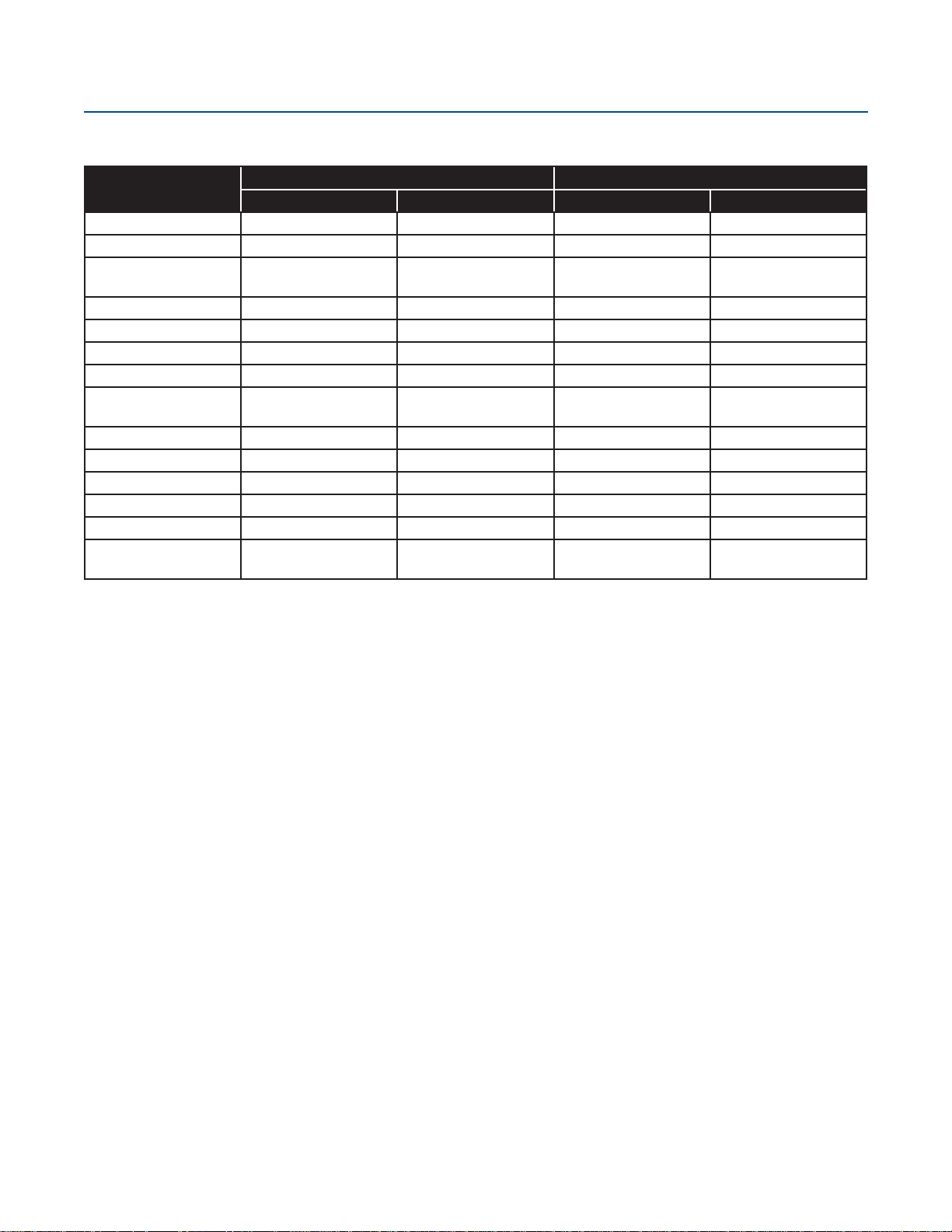
Specications
APPS 160 & APPS 160 (220V)
APPS 160 APPS 160 (220V)
PN 11914406 PN 11918618 PN 13417171 PN 13417180
Operating Pressure 10 to 50 psig 40 to 85 psig 10 to 50 psig 40 to 85 psig
Height 61 9/16” 61 9/16” 61 9/16” 61 9/16”
Width 30 3/16”
(20” OD cylinder)
Weight (empty) 210 pounds 210 pounds 210 pounds 210 pounds
Capacity (gross) 42 gallons / 160 liters 42 gallons / 160 liters 42 gallons / 160 liters 42 gallons / 160 liters
Cryogenic uids* Nitrogen Nitrogen Nitrogen Nitrogen
Inlet connection 1/2” male 45° are 1/2” male 45° are 1/2” male 45° are 1/2” male 45° are
Outlet connection 1” female MVE
bayonet
Vent connection 1/2” female pipe thread 1/2” female pipe thread 1/2” female pipe thread 1/2” female pipe thread
MAWP 100 psi 100 psi 100 psi 100 psi
Max inlet pressure 235 psi 235 psi 235 psi 235 psi
Max withdrawal rate 15 gpm continuous 15 gpm continuous 15 gpm continuous 15 gpm continuous
Steady state noise 98 - 106 dB 98 - 106 dB 98 - 106 dB 98 - 106 dB
Power requirement 110 Volt / 60 Hz 200
watts
* Oxygen and argon service available upon special request. Specications subject to change at any time without notice.
30 3/16”
(20” OD cylinder)
1” female MVE
bayonet
110 Volt / 60 Hz 200
watts
30 3/16”
(20” OD cylinder)
1” female MVE
bayonet
220 Volt / 50 Hz 220 Volt / 50 Hz
30 3/16”
(20” OD cylinder)
1” female MVE
bayonet
9
Page 14
Specications Product Manual - APPS 160
10
Service
• The APPS 160 should only be serviced by a
knowledgable technician
• Power should be disconnected before covers are removed
• Liquid nitrogen and all pressure should be released before
any plumbing component is removed
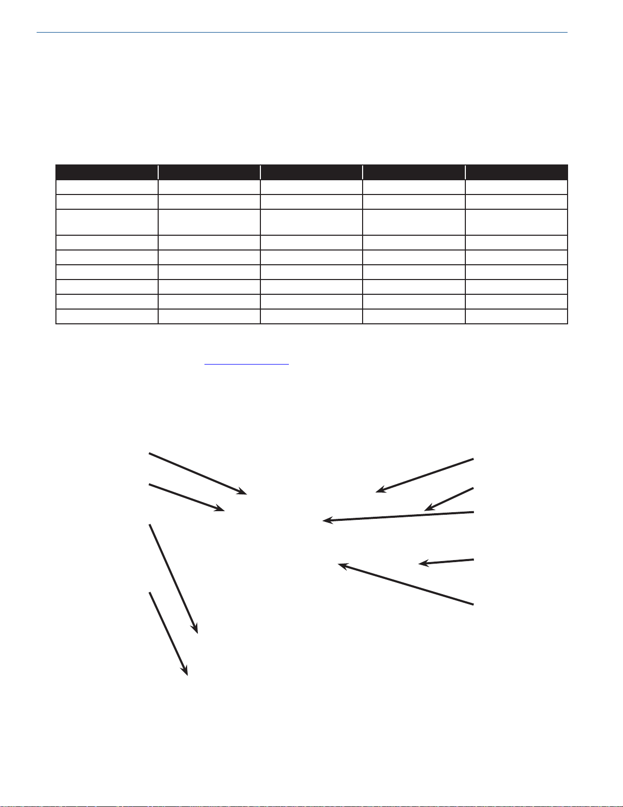
• Potential service parts are as follows:
from the control box, pressure switch or liquid level
switch If not, these boxes will contain “hot” wires and/or
wires that will become “hot” without notice
Part Description 11914406 (10-50 psig) 11918618 (40-85 psig) 13417171 (10-50 psig) 13417180 (40-85 psig)
Vessel PRV (100 psig) 11915572 11915572 11915572 11915572
Vessel SRV (150 psig) 11915581 11915581 11915581 11915581
Inlet piping RV (235
psig)
Vent regulator 11756911 2110582 11756911 2110582
Fill or vent valve 11542577 11542577 13428217 13428217
Pressure switch 10805996 11860241 10805996 11860241
Liquid level switch 11841147 11841147 11841147 11841147
Inlet strainer 11529090 11529090 11529090 11529090
Inlet check valve 11208931 11208931 11208931 11208931
1810062 1810062 1810062 1810062
See pictures on following pages for the identication of components.
All parts are available from Chart at www chartparts com
Fill Valve
Inlet Piping
RV
Liquid Level
Switch
Pressure
Switch
Vent
Regulator
Vent Valve
Liquid Level
Indicator
Vessel PRV
Pressure
Gauge
Page 15

Inlet Check
Valve
Inlet Strainer
Inlet
Connection
SpecicationsProduct Manual - APPS 160
11
Control Box
On / Off
Switch
Fill Valve
Indicator Light
Vent Valve
Indicator Light
Page 16

Specications Product Manual - APPS 160
12
Control Box
hot - black wire
connection
Control Box
neutral - white wire
connection
Control Box
ground - green wire
connection
Liquid Level
switch
connections
Liquid Level
switch adjustment
Page 17

Pressure
switch
connections
Control Box Electrical Schematic
SpecicationsProduct Manual - APPS 160
Pressure
switch
adjustments
13
Page 18

14
Product Manual - APPS 160
 Loading...