

Page 1

Product Manual
Perma-Cyl® MicroBulk Storage System
w/ FlexFill™ Piping Option
1000/1500/2000/3000/5500
Designed and Built by:
Chart Inc.
1300 Airport Dr.
Ball Ground, GA 30107 USA
(800) 400-4683
Part Number 20930593 Rev. C
© 2016 Chart Inc.
Page 2

Page 3

Product Manual - Perma-Cyl® w/ FlexFill™ Piping Option
Contents
Revision Log iv
Preface. . . . . . . . . . . . . . . . . . . . . . . . . . . . . . . . . . . . . . . . . . . . . . . . . . . . .1
General 1
Product Highlights 1
Product Manual 1
Terms 2
Acronyms / Abbreviations 2
Safety . . . . . . . . . . . . . . . . . . . . . . . . . . . . . . . . . . . . . . . . . . . . . . . . . . . . .3
General 3
Safety Bulletin 3
Oxygen Decient Atmospheres 4
Oxygen Cleaning 4
Oxygen Enriched Atmospheres 5
Nitrogen and Argon 5
Personal Protective Equipment (PPE) 5
Introduction/Operation. . . . . . . . . . . . . . . . . . . . . . . . . . . . . . . . . . . . . . . . . . . .7
General 7
Initial Inspection 7
Vacuum Check Procedure - Perma-Cyl 5500 Only 7
Primary Plumbing Circuits 8
Fill 8
Pressure Build 9
Economizer 9
Liquid Use 9
Gas Use 9
Safety Circuit 10
Vent/Full Trycock 10
Other Piping Circuits and Components 10
Phase Lines and Liquid Level Gauges 10
Four-Way Valve (see photos 1 & 2) 10
Pressure Gauge (see photos 1 & 2) 10
Vacuum Evacuation Port 11
2000/3000VHP Operation 11
2000 and 3000 VHP Primary Plumbing Circuits 11
5500 MP/VHP Operation 13
5500 MP/VHP Primary Plumbing Circuits 13
Vacuum Integrity 15
iii
Installation. . . . . . . . . . . . . . . . . . . . . . . . . . . . . . . . . . . . . . . . . . . . . . . . . .17
Unloading and Placement of the Perma-Cyl Tank 17
Installation Common Codes and Standards 17
Conducting a Site Evaluation 17
Installation Tools and Supplies 17
Supplies 17
Tools 17
Additional Required Supplies 18
Indoor Installations 19
Internally Sited / Filled Indoors / Pipe Out Safeties 19
Wall Box 19
Installation of Hoses and Lines 19
General 19
Line Connection to Fill Box Panel 19
Bolting to Floor 21
Page 4
Table of Contents Product Manual - Perma-Cyl® w/ FlexFill™ Piping Option
iv
Outdoor Installations 21
Externally Sited / Gas Use Indoors 22
Outdoor Installation Schematic 22
First Fill/Purge Procedure 22
Purging and First Fill Procedure 22
Filling the Tank After the Cool Down Process is Complete 23
Troubleshooting. . . . . . . . . . . . . . . . . . . . . . . . . . . . . . . . . . . . . . . . . . . . . . .25
Specications . . . . . . . . . . . . . . . . . . . . . . . . . . . . . . . . . . . . . . . . . . . . . . . . 31
Illustrations & Parts Listing . . . . . . . . . . . . . . . . . . . . . . . . . . . . . . . . . . . . . . . . 33
1000 HP/VHP FlexFill 33
1500 HP/VHP FlexFill 36
2000 HP FlexFill 39
3000 HP FlexFill 42
2000 VHP FlexFill 45
3000 VHP FlexFill 48
5500 VHP FlexFill 51
5500 MP FlexFill 54
Warranty . . . . . . . . . . . . . . . . . . . . . . . . . . . . . . . . . . . . . . . . . . . . . . . . . . 59
Revision Log
Revision Level Date Description
A 11/24/2015 Original manual
B 02/22/2016 Add information on thermocouple to the end of 5500 VHP Operation section
C 09/08/2016 Add information for 5500 MP model; update Filling Weight Table
Page 5

Product Manual - Perma-Cyl® w/ FlexFill™ Piping Option
Preface
1
General
The new Perma-Cyl FlexFill storage vessel is equipped with
a top and bottom ll circuit in place of the top oat assembly
so the driver can control the tank pressure while lling the
Perma-Cyl
uses the ullage technology adopted from our LNG fueling
system which allows the inner vessel to safely go liquid full
Once the meter on the Orca™ MicroBulk Delivery System
senses a ow rate reduction, the pump is automatically shut
down. This patented automatic dispensing system simulates
the same process drivers have used for years to safely ll
Perma-Cyl storage tanks without venting
The FlexFill feature is critical for applications like laser
assist gas and medical gas supply where a signicant drop in
downstream pressure during the Perma-Cyl tank rell could
result in equipment alarms. The new FlexFill feature works
with all Orca delivery unit models, both new and existing
units
*Perma-Cyl tanks with the FlexFill Piping Option are
presently not approved for service with CO2.
®
MicroBulk Storage System. The FlexFill option
Product Highlights
• Allows top and bottom lling for accurate pressure
control in the Perma-Cyl tank during rell
• Provides the same safe, single hose, no-loss, auto shutoff ll with the Orca delivery system as the top ll oat
design
Product Manual
This manual contains information regarding the safe
operation and maintenance of a Perma-Cyl tank w/ FlexFill
piping option. It should be thoroughly read and understood
by anyone that operates the equipment.
The safety requirements for operating the tank and handling
or transporting extremely cold liquid products are shown
in the Safety section Use this safety section as a “Safety
Checklist” each time the equipment is being used.
The Introduction/Operation section discusses the general
features of the tank and the theory of operation.
In the Installation section there are illustrations for how to
uncrate and install the tank
The remaining sections describe the specic tank models
covered by this manual. They contain warranty information,
troubleshooting help, technical specications/illustrations,
and parts lists. They should be reviewed rst and referred to
as the rest of the manual is read
The Illustrations & Parts Listing section contains schematics,
piping illustrations, and parts list that show a reference
number for each component used on the tank. The reference
numbers may refer to the same functional component
between the various models The reference numbers will be
used throughout this manual to draw specic attention to a
component while describing its function, operation, or repair.
• Backward compatible - works with new and existing Orca
delivery units without modications
• Incorporates the lling technology from the LNG vehicle
& dispenser system
• Comes standard with dual relief valves and rupture discs
• Utilizes separate pressure build and economizer
regulators
Page 6

Preface Product Manual - Perma-Cyl® w/ FlexFill™ Piping Option
2
Terms
Throughout this manual safety precautions will be designated
as follows:
Warning! Description of a condition that
can result in personal injury or
death.
Caution! Description of a condition that
can result in equipment or
component damage.
Note: A statement that contains information
that is important enough to emphasize or
repeat.
Acronyms / Abbreviations
The following acronyms / abbreviations are used throughout
this manual:
Ar Argon
ASME American Society of Mechanical Engineers
BARG Pressure (Metric) Gauge
CGA Compressed Gas Association
CO2 Carbon Dioxide
DOT Department of Transportation
FPT Female Pipe Thread
ID Inner Diameter
Kg Kilogram
LAR Liquid Argon
MA WP Maximum Allowable Working Pressure
N2 Nitrogen
Nm3 Normal Cubic Meters
Nm3h Normal Cubic Meters/Hour
NER Normal Evaporation Rate
NFPA National Fire Protection Association
NPT National Pipe Thread
O2 Oxygen
PB Pressure Builder
PSI Pounds per Square Inch
PSIG Pounds per Square Inch (Gauge)
SCF Standard Cubic Feet
SCFH Standard Cubic Feet/Hour
UFC Uniform Fire Code
Page 7

Product Manual - Perma-Cyl® w/ FlexFill™ Piping Option
Safety
3
General
While Chart equipment is designed and built to the most
rigid standards, no piece of mechanical equipment can
ever be made 100% foolproof. Strict compliance with
proper safety and handling practices are necessary when
using a cryogenic manifold device or other compressed
gas equipment. We recommend that all of our customers
re-emphasize safety and safe handling practices to all their
employees and customers. While every possible safety
feature has been designed into the Perma-Cyl® MicroBulk
Storage System w/ FlexFill
operations are anticipated, it is essential that the customer
carefully read and fully understand all Warning and Caution
notes listed below
Warning! The Perma-Cyl tank, with its
Warning! Any welding that is done on the
™
Piping Option and safe
stainless steel support system
is designed, manufactured, and
tested to function normally for
many years of service. It is never
safe to drop a liquid cylinder or
let it fall over in oxygen or any
cryogenic service. In the event
a liquid cylinder is inadvertently
dropped, tipped over, or abused,
slowly raise it to its normal
vertical position and immediately
open the vent valve to release
any excess pressure in a safe
manner. As soon as possible,
remove the liquid product from
the vessel in a safe manner.
If the vessel has been used in
oxygen service, purge it with an
inert gas (nitrogen). If damage is
evident or suspected, return the
unit to Chart prominently marked
“LIQUID CYLINDER DROPPED,
INSPECT FOR DAMAGE”.
outside of the Perma-Cyl System
can cause loss of vacuum and
will VOID any warranty on the
unit.
Warning! Before removing cylinder parts
or loosening ttings, completely
empty the liquid cylinder of
liquid and release the entire
vapor pressure in a safe manner.
External valves and ttings can
become extremely cold and may
cause painful burns to personnel
unless properly protected.
Personnel must wear protective
gloves and eye protection
whenever removing parts or
loosening ttings. Failure to do
so may result in personal injury
because of extreme cold and
pressure in the cylinder.
Caution! Only use replacement equipment
which is compatible with liquid
oxygen and has been cleaned
for oxygen use. Do not use
regulators, ttings, hoses, etc.,
which have been previously
used in compressed air service.
Failure to comply with these
instructions may result in serious
damage to the liquid cylinder and
personal injury.
Caution! All valves on an empty Perma-
Cyl system should always be
kept closed to protect the inner
vessel and plumbing from being
contaminated.
Safety Bulletin
Portions of the following information are extracted from
Safety Bulletin SB-2 from the Compressed Gas Association,
Inc. Additional information on oxygen, nitrogen, argon, and
cryogenics is available from the CGA
Cryogenic containers, stationary or portable, are from time
to time subjected to assorted environmental conditions of
an unforeseen nature This safety bulletin is intended to call
attention to the fact that whenever a cryogenic container
is involved in any incident whereby the container or its
safety devices are damaged, good safety practices must be
followed The same holds true whenever the integrity or
function of a container is suspected of abnormal operation.
Incidents which require that such practices be followed
include: highway accidents, immersion of a container in
Page 8

Safety Product Manual - Perma-Cyl® w/ FlexFill™ Piping Option
4
water, exposure to extreme heat or re, and exposure to most
adverse weather conditions (earthquake, tornadoes, etc.).
Under no circumstances should a damaged container be left
with product in it for an extended period of time.
Prior to reusing a damaged container, the unit must be
tested, evaluated, and repaired as necessary. It is highly
recommended that any damaged container be returned to
Chart for repair and re-certication.
In the event of known or suspected container vacuum
problems (even if extraordinary circumstances such as
those noted above has not occurred), do not continue to use
the unit Continued use of a cryogenic container that has a
vacuum problem can lead to embrittlement and cracking.
The remainder of this safety bulletin addresses those adverse
environments that may be encountered when a cryogenic
container has been severely damaged These are oxygen
decient atmospheres, oxygen enriched atmospheres, and
exposure to inert gases.
Caution! Before locating oxygen
equipment, become familiar
with the NFPA standard No.
55 “Compressed Gases and
Cryogenic Fluids Code” (www.
nfpa.org) and with all local safety
codes.
diagnosing the situation because the onset of symptoms
such as sleepiness, fatigue, lassitude, loss of coordination,
errors in judgment and confusion can be masked by a state of
“euphoria,” leaving the victim with a false sense of security
and well being
Human exposure to atmosphere containing 12% or less
oxygen leads to rapid unconsciousness. Unconsciousness can
occur so rapidly that the user is rendered essentially helpless.
This can occur if the condition is reached by an immediate
change of environment, or through the gradual depletion of
oxygen
Most individuals working in or around oxygen decient
atmospheres rely on the “buddy system” for protection obviously the “buddy” is equally susceptible to asphyxiation
if he or she enters the area to assist the unconscious partner
unless equipped with a portable air supply. Best protection
is obtainable by equipping all individuals with a portable
supply of respirable air. Life lines are acceptable only if the
area is essentially free of obstructions and individuals can
assist one another without constraint
If an oxygen decient atmosphere is suspected or known to
exist:
1 Use the “buddy system ” Use more than one “buddy” if
necessary to move a fellow worker in an emergency
2 Both the worker and “buddy” should be equipped with
self-contained or airline breathing equipment.
Oxygen Decient Atmospheres
Warning! Nitrogen and argon vapors in air
may dilute the concentration of
oxygen necessary to support or
sustain life. Exposure to such
an oxygen decient atmosphere
can lead to unconsciousness and
serious injury, including death.
The normal oxygen content of air is approximately 21%.
Depletion of oxygen content in air, either by combustion
or by displacement with inert gas, is a potential hazard and
users should exercise suitable precautions.
One aspect of this possible hazard is the response of humans
when exposed to an atmosphere containing only 8 to 12%
oxygen. In this environment, unconsciousness can be
immediate with virtually no warning
When the oxygen content of air is reduced to about 15
to 16%, the ame of ordinary combustible materials,
including those commonly used as fuel for heat or light,
may be extinguished. Somewhat below this concentration,
an individual breathing the air is mentally incapable of
Oxygen Cleaning
When replacing components, only use parts which are
considered compatible with liquid oxygen and have been
properly cleaned for oxygen service (Refer to CGA Bulletin
G-4.1 “Equipment Cleaned for Oxygen Service”). Do not
use regulators, ttings, or hoses which were previously
used in a compressed air environment on these tanks. Only
oxygen compatible sealants or Teon tape should be used on
threaded ttings. All new piping joints should be leak tested
with an oxygen compatible leak-test solution.
Caution! Failure to comply with these
instructions may result in serious
damage to the system and
personal injury.
Page 9

SafetyProduct Manual - Perma-Cyl® w/ FlexFill™ Piping Option
5
Oxygen Enriched Atmospheres
An oxygen-enriched atmosphere occurs whenever the normal
oxygen content of air is allowed to rise above 23% While
oxygen is nonammable, ignition of combustible materials
can occur more readily in an oxygen-rich atmosphere than
in air; and combustion proceeds at a faster rate although no
more heat is released
It is important to locate an oxygen system in a well
ventilated location since oxygen-rich atmospheres may
collect temporarily in conned areas during the functioning
of a safety relief device or leakage from the system
Oxygen system components, including but not limited to,
containers, valves, valve seats, lubricants, ttings, gaskets
and interconnecting equipment including hoses, shall have
adequate compatibility with oxygen under the conditions
of temperature and pressure to which the components may
be exposed in the containment and use of oxygen. Easily
ignitable materials shall be avoided unless they are parts of
equipment or systems that are approved, listed, or proven
suitable by tests or by past experience.
Compatibility involves both combustibility and ease of
ignition. Materials that burn in air may burn violently in pure
oxygen at normal pressure, and explosively in pressurized
oxygen. In addition, many materials that do not burn in
air may do so in pure oxygen, particularly when under
pressure. Metals for containers and piping must be carefully
selected, depending on service conditions. The various steels
are acceptable for many applications, but some service
conditions may call for other materials (usually copper or
its alloy) because of their greater resistance to ignition and
lower rate of combustion
Nitrogen and Argon
Nitrogen and argon (inert gases) are simple asphyxiates.
Neither gas will support or sustain life and can produce
immediate hazardous conditions through the displacement
of oxygen. Under high pressure these gases may produce
narcosis even though an adequate oxygen supply sufcient
for life is present.
Nitrogen and argon vapors in air dilute the concentration
of oxygen necessary to support or sustain life. Inhalation
of high concentrations of these gases can cause anoxia,
resulting in dizziness, nausea, vomiting, or unconsciousness
and possibly death. Individuals should be prohibited from
entering areas where the oxygen content is below 19%
unless equipped with a self-contained breathing apparatus.
Unconsciousness and death may occur with virtually no
warning if the oxygen concentration is below approximately
8% Contact with cold nitrogen or argon gas or liquid can
cause cryogenic (extreme low temperature) burns and freeze
body tissue
Persons suffering from lack of oxygen should be
immediately moved to areas with normal atmospheres.
SELF-CONTAINED BREATHING APPARATUS MAY BE
REQUIRED TO PREVENT ASPHYXIATION OF RESCUE
WORKERS. Assisted respiration and supplemental oxygen
should be given if the victim is not breathing If cryogenic
liquid or cold boil-off gas contacts worker’s skin or eyes,
the affected tissue should be ooded or soaked with tepid
water (105-115ºF or 41-46ºC). DO NOT USE HOT WATER.
Cryogenic burns that result in blistering or deeper tissue
freezing should be examined promptly by a physician.
Similarly, materials that can be ignited in air have lower
ignition energies in oxygen Many such materials may
be ignited by friction at a valve seat or stem packing, or
by adiabatic compression produced when oxygen at high
pressure is rapidly introduced into a system initially at low
pressure.
Warning! If clothing should be splashed
with liquid oxygen it will become
highly ammable and easily
ignited while concentrated
oxygen remains. Such clothing
must be aired out immediately,
removing the clothing if possible,
and should not be considered
safe for at least 30 minutes.
Personal Protective Equipment (PPE)
The following personal protective equipment is
recommended when working around cryogenic liquid:
• Safety glasses with side shields to prevent cryogenic
liquid from splashing into the eyes
• Chemical / Liquid resistant gloves to prevent cryogenic
burns on exposed hands
• Long sleeve shirts to protect the arms
• Cufess trousers worn over closed shoes
Page 10

Page 11

Product Manual - Perma-Cyl® w/ FlexFill™ Piping Option
Introduction/Operation
7
General
The Perma-Cyl® MicroBulk Storage System w/ FlexFill™
Piping Option is designed to store and deliver liquid
oxygen, nitrogen or argon as a cryogenic liquid or gas.
The Perma-Cyl tank can build and maintain pressure from
the automatically regulated pressure building circuit.
A continuous gas ow is provided from the cylinders.
Regardless of size, all Perma-Cyl tank models operate on the
same principals of operation.
Caution! Only use replacement equipment,
which is compatible with liquid
oxygen and has been cleaned
for oxygen use. Do not use
regulators, ttings, hoses, etc.,
which have been previously used
in compressed air. Failure to
comply with these instructions
may result in serious damage to
the system and personal injury.
Initial Inspection
Receiving inspection is one of the most important operations
in the life of the tank and should be done thoroughly and
conscientiously so as to nd any possible indications of
damage and prevent expensive surprises during the rst
use of the vessel at the site. Upon receipt of a Perma-Cyl
tank, remove the protective wrapping and inspect for the
following:
• Any shipping damage including dents, cuts, broken and
bent plumbing components. Report any ndings to the
shipping company immediately.
• Examine welded and brazed joints on plumbing for
cracks or deformation, especially on valves and ttings.
• On the 5500 Perma-Cyl tanks check the insulation space
pressure with a suitable thermocouple vacuum gauge
(follow procedure below). Make a note of the ambient
temperature when the vacuum is read. Temperature
changes affect the vacuum reading in a warm empty
vessel
– If warm vacuum is above 20 microns, consult factory.
Vacuum Check Procedure - Perma-Cyl 5500 Only
The standard Chart vacuum probe is a Teledyne-Hastings
DV-6R probe. Select a compatible instrument to read the
output of the vacuum probe.
Caution! Unauthorized changing of the
vacuum probe will void vessel
warranty.
1 Remove rubber cap on probe outlet to expose contact.
Note that the probe housing need not be opened to do
this
2 Plug the instrument in to the probe and calibrate the
instrument
3 Open the vacuum probe isolation valve. Wait for ve
minutes and take vacuum reading Note that valve
handle protrudes through protective housing and can be
turned without opening the housing.
4 Close the isolation valve and take a second reading
Monitor the rate of rise in vacuum probe with isolation
valve closed If the vacuum continues to rise at a
constant rate, it is possible that the probe assembly is
leaking Consult the factory
• Check burst discs and relief valves for dirt/damage
• Check to ensure there is positive pressure on the inner
vessel, normally about 20-25 psig. Tanks are shipped
with NF purity nitrogen gas. Purging is necessary prior to
lling.
• If the tank passes all the above criteria, it is ready for
rst ll. Follow the rst ll procedures in the Installation
portion of this manual.
Note: The PC5500 is the only Perma-Cyl
tank that is equipped with a vacuum
thermocouple.
5 Verify that the isolation valve is closed
6 Replace the rubber probe cap.
7 Compare the vacuum reading obtained now to the
reading taken prior to shipping.
Page 12

Introduction/Operation Product Manual - Perma-Cyl® w/ FlexFill™ Piping Option
8
Color Code:
Fill Circuit
PB Circuit
Economizer Circuit
Gas Use Circuit
Safety Circuit
Liquid Circuit
Figure 1 - Schematic for 1000HP/VHP, 1500HP/VHP, 2000HP and 3000HP models.
Primary Plumbing Circuits
(Refer to Figure 1)
Fill
The Perma-Cyl w/ FlexFill has a top and bottom ll circuit
that replaces the top oat assembly so the driver can control
the tank pressure while lling the Perma-Cyl MicroBulk
Storage Tank. The ll circuit consists of a top ll valve (V-6),
a bottom ll valve (V-5), a ll check valve (CV-1), and a
hose drain valve (V-3). The ll line check valve has a service
tting on the inlet side that provides the sole connection for
the liquid delivery vehicle
The hose drain valve (V-3) can be used to both purge the ll
hose before lling the tank or to depressurize the ll hose
after lling the tank.
The driver controls the pressure in the vessel during the ll
process by adjusting the ow through the top and bottom ll
valves. Product owing into the bottom of the tank will raise
the pressure and product owing into the top of the tank will
lower the pressure. Adjusting each valve properly will allow
the driver to hold a consistent pressure in the tank throughout
the entire delivery
During a rst ll, only ll the vessel to 75% full to allow
liquid expansion experienced with a new "hot" tank. Each
ll there after can be lled to 100% full. Please refer to
the Installation section of this manual for detailed lling
procedures.
Caution! If liquid can be trapped in the
transfer system, a suitable relief
valve must be installed to prevent
over pressurization.
Page 13

Introduction/OperationProduct Manual - Perma-Cyl® w/ FlexFill™ Piping Option
9
Caution! Before making a liquid transfer
either into or out of this
vessel, be sure that protective
eyeglasses and gloves are being
worn. If the transfer is being
made to an open top vessel, the
transfer pressure should be as
low as possible and a phase
separator should be used to
eliminate splashing and hose
whip.
Pressure Build
The pressure build circuit is used to build pressure back in
the vessel after a delivery or to maintain pressure as liquid
is withdrawn from the vessel. The vessel pressure is set by
adjusting the PB regulator (R2). Standard PB set points are:
MP - 125 psig
HP - 300 psig
VHP - 450 psig
As the tank pressure drops below the PB set point, the
regulator opens and allows liquid to ow off the bottom of
the tank, through the internal PB vaporization coils, through
the R-1 and back into the gas phase of the tank. The pressure
build circuit can be isolated by closing valves V-12 & V-13.
Some models of Perma-Cyl tanks can be equipped with
external pressure build vaporizers which allow for much
quicker recoveries after the tank has been blown down to ll
it or for high ow applications.
Liquid Use
The liquid use circuit can be used for both a liquid
application or a high ow gas use application. This circuit
draws liquid directly up the dip tube and out through
the liquid use valve (V-4). Some models have a bottom
withdrawal valve that draws liquid out the bottom of the
inner. For a high ow gas use application the liquid can be
piped through a stand alone external process vaporizer. This
can more than double the standard ow rates that can be
achieved through the internal vaporization coils.
Gas Use
The gas use valve (V-1) leverages the internal vaporizer on
the Perma-Cyl system to supply gaseous product to the end
user
Note: The liquid is drawn up the dip tube,
through the top knuckle and back down
through the internal vaporization coil
before exiting out the gas use valve.
The internal vaporizer can support specic ow rates. The
gas use valve used is a 1/2" globe valve. The line size for the
gas use should be sized properly for the pressure and ow
rate that is desired
The Perma-Cyl tank will deliver gas at various ow rates and
temperatures for different applications. The equipment that
is being supplied gas from the Perma-Cyl tank controls the
ow rate. Higher ow rates may provide very cold gas that
could damage the equipment to which they are attached. To
supply gaseous product, follow this step by step procedure.
1 Connect the proper regulator/regulating manifold to the
liquid cylinder's gas use outlet
Economizer
The economizer circuit allows the customer to utilize the
natural heat leak that occurs in every cryogenic storage
vessel. When the pressure is above the setpoint of the
economizer regulator, the economizer regulator (R-1) opens.
This allows gas to be withdrawn directly off the headspace
of the tank and travel through the internal vaporization coils,
to warm the cold gas, and out the gas use valve. This will
result in lowering the pressure of the tank. The economizer
regulator can be isolated by closing valves V-2 and V-10
Note: The economizer circuit will only work if
the customer is using product out of the
vessel.
2 Connect the proper piping between the nal line
regulator and the receiving equipment.
3 Open the pressure building valve.
4 Allow pressure to build to the operating pressure (refer
to gauge).
5 Open the gas use valve.
6 Adjust the gas use regulator for the proper delivery
pressure.
Caution! All valves on an empty Perma-
Cyl tank should always be kept
closed to protect the inner
vessel and plumbing from being
contaminated.
Page 14
Introduction/Operation Product Manual - Perma-Cyl® w/ FlexFill™ Piping Option
10
The operator should review the safety precautions found
in the Safety section before conducting a gas or liquid
withdrawal operation. Protective eyeglasses and gloves
should always be worn
At low ow rates, the Perma-Cyl tank is capable of
delivering warm gas through the line regulator. As the ow
rate increases, the temperature of the gas decreases. If the
cold temperature becomes a problem at a desired ow rate,
an external vaporizer can be added. Attach this vaporizer
directly in series with the gas use connection and place the
line regulator at the exit of the vaporizer.
Safety Circuit
The Perma-Cyl w/ FlexFill Piping Option tanks are equipped
with dual spring operated relief valves (RV-2) and dual burst
discs (BD-1). The dual safety manifold with diverter valve
(V-8) is standard on these vessels. This allows for change
out of safety relief devices without the need to empty the
tank These devices are used to automatically relieve excess
pressure in the vessel and cannot be isolated by use of a
valve. Replacement of these relief devices should only be on
a "like for like" basis. Substitutes should be avoided unless
approved by the manufacturer. Purge valves (V-7) can be
used to relieve pressure before removing safety devices.
Vent/Full Trycock
gauge (Ll-1) which is used to indicate the amount of product
in the vessel The standard DP gauge used by Chart is the
Cyl-Tel
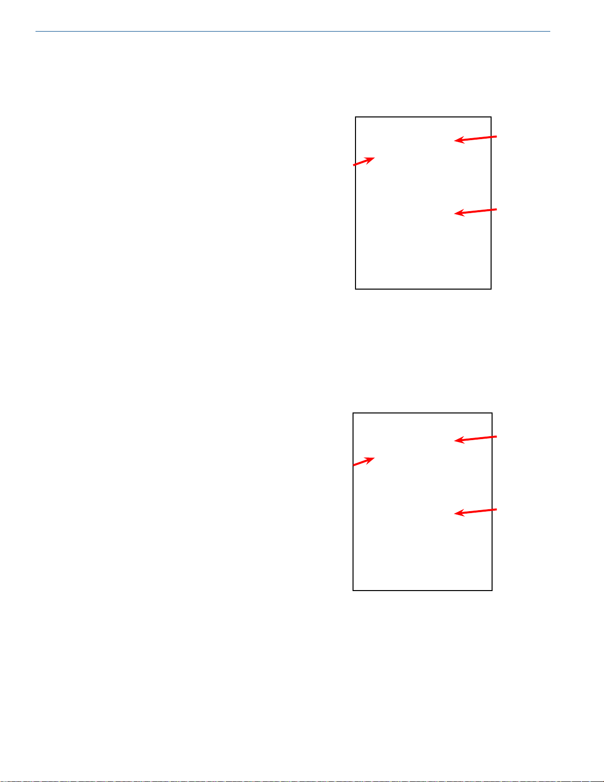
®
Liquid Level Gauge. Customers can specify other
models as options such as the WIKA Analog DP Gauge (see
photos 1 & 2 on next page).
Pressure
Gauge
Four-Way
Valve
Cyl-Tel®
Liquid Level
Gauge
Photo 1
Four-Way Valve (see photos 1 & 2)
The four-way valve (V-11) is used as the primary isolation
valve between the DP gauge and the phase lines from the
tank. This four-way valve also provides an easy method to
check the zero on the DP gauge By turning the valve into
the equalization position, the DP gauge can be zeroed and
isolated from the tank pressure for removal or replacement.
The vent valve (V-9) is used to relieve excess pressure in
the cylinder On Perma-Cyl systems the vent valve is a gray
handled globe valve. When installed indoors, the vent line
should be piped outdoors using 1/2" nominal copper or the
equivalent stainless steel hose The vent valve also serves as
the full trycock during lling operations. When the PermaCyl tank is lled by trucks other than Orca
™
MicroBulk
Delivery System trucks, the full trycock must be used to ll
the vessel. When liquid starts to spit out of this valve while
being lled, the lling process should be terminated.
Other Piping Circuits and Components
Phase Lines and Liquid Level Gauges
The Perma-Cyl tank is equipped with both a low pressure
phase line (F) located on the top of the vessel and a high
pressure liquid phase line (E) located on the bottom of the
vessel. These lines are connected to a differential pressure
Pressure
Gauge
Four-Way
Valve
WIKA
Analog DP
Gauge
Photo 2
Pressure Gauge (see photos 1 & 2)
A single pressure gauge (R-1) on the Perma-Cyl tank is also
tied into the low phase line and gives the operator a pressure
reading in the gas phase of the vessel. This pressure gauge
can also be isolated with the four-way valve
Page 15

Vacuum Evacuation Port
Unlike bulk tanks, Perma Cyl storage vessels are normally
not provided with an on-board method of taking a vacuum
reading. The vacuum evacuation port is sealed using a
stainless steel disk with O-rings and a protective cover is
placed over it (see Photo 3). Due to the relatively small
volume of the annular vacuum space, taking vacuum
readings is normally not recommended since the vacuum
level is slightly reduced when taking this reading The
troubleshooting portion of this manual gives steps on how
to determine if the vacuum might be weak In the event
that the vacuum does need to be checked, a trained vacuum
technician would have to bring the appropriate equipment
to get this done In most cases where a vacuum has been
compromised, it is often more economical to swap out the
tank
Introduction/OperationProduct Manual - Perma-Cyl® w/ FlexFill™ Piping Option
Evacuation
Port
Photo 3 - Vacuum Evacuation Port with Cover
11
Figure 2 - Schematic for 2000/3000 VHP
2000/3000VHP Operation
The plumbing design for the 2000/3000 VHP Perma-Cyl
system is different from the models described in the previous
section. These models do not contain internal vaporization
or pressure build coils. For the 2000 and 3000 models, all
pressure building and process vaporization is provided by
two external vaporizers. This plumbing conguration is
commonly referred to as Option 09 or the ZX package.
2000 and 3000 VHP Primary Plumbing Circuits
(Refer to Figure 2)
Fill
The Fill Plumbing Circuit on these two models is the same as
the models described in the previous section (see page 8).
Page 16

Introduction/Operation Product Manual - Perma-Cyl® w/ FlexFill™ Piping Option
12
Pressure Build
The pressure build circuit for the 2000 and 3000 VHP
Perma-Cyl models is used to build pressure back in the
vessel after a delivery or to maintain pressure as liquid is
withdrawn from the vessel. The vessel pressure is set by
adjusting the PB Regulator (R1) shown in Figure 2. Standard
PB set points found in the 09 plumbing option kits are:
MP - 125-09
HP - 300-09
VHP - 450-09
Liquid is drawn off the bottom of the tank, runs through the
PB regulator (R-1), then is vaporized by running through
both the PB vaporizer and the gas use vaporizer. The
vaporized gas then splits and a portion ows through check
valve CV-3 and back to the headspace of the tank. The other
portion goes directly to the customer through the gas use
valve V-1 Liquid serving both the PB and gas use can be
shut off by closing valve V-2
Note: Closing valve V-1 or V-2 will cut off any
process gas going to the customer through
the gas use valve.
Gas Use
The gas use valve (V-1) on the 2000 and 3000 VHP PermaCyl models is the primary connection point to supply process
gas to the customer. Unlike the other Perma-Cyl models,
the liquid for the process gas comes directly off the bottom
of the tank (C) and travels through the PB regulator (R-1).
The unique design of this model allows for both the PB
vaporizer and the gas use vaporizer to be utilized for process
gas vaporization. After exiting the gas use vaporizer, the gas
splits and supplies both the pressure build and the gas use as
explained in the pressure build explanation for this particular
model of tank
Note: Since all the liquid for both the PB and gas
use requirements of this model tank travels
through one regulator (R-1), the limiting
factor on ow is this regulator. A high
ow kit is offered for the 2000 and 3000
VHP tanks. This kit adds an additional PB
regulator in parallel with the existing PB
regulator (R-1) allowing for ows up to
3500 SCFH (see Photo 4).
Economizer
The economizer circuit allows for the customer to utilize
the natural heat leak that occurs in every cryogenic storage
vessel The economizer circuit for the 2000 and 3000 VHP
models is comprised of a check valve (CV-4) which draws
gas directly off the top of the tank and sends it through the
gas use vaporizer in order to warm up the cold vapor prior
to exiting the tank through the gas use valve Flow through
the 1 psig cracking pressure check valve (CV-4) only
occurs when regulator R-1 closes Valve V-10 shuts off the
economizer circuit
Liquid Use
The liquid use circuit for both the 2000 and 3000 VHP
models is similar to the other Perma-Cyl models This circuit
draws liquid directly up the dip tube and out through the
liquid use valve (V-4). For high ow gas use applications,
the liquid can be piped from the liquid use valve (V-4) to a
stand-alone external vaporizer that is properly sized for the
owrate. In this scenario, the gas use valve on the tank is not
used so the PB and gas use external vaporizers on the tank
become dedicated to pressure building only.
Photo 4 - High Flow Kit
All other plumbing circuits that are covered on pages 9 and
10 of this manual also apply to the 2000 and 3000 VHP
Perma-Cyl models. These include the safety circuit, vent/
full trycock, high/low phase lines, liquid level gauges and
pressure gauges.
Page 17

Introduction/OperationProduct Manual - Perma-Cyl® w/ FlexFill™ Piping Option
13
Figure 3 - Schematic with vaporizer for 5500 MP/VHP models.
5500 MP/VHP Operation
For the 5500 model, a single external vaporizer provides
all pressure building vaporization. An optional 3500 SCFH
hang-on or optional 5000 SCFH stand alone vaporizer may
be added to the plumbing to provide all process vaporization.
This plumbing conguration is referred to as Option 07 and
is unique to the 5500 model
5500 MP/VHP Primary Plumbing Circuits
(Refer to Figure 3)
Fill
The standard ll plumbing circuit is exactly the same as all
the other Perma-Cyl models (refer to page 8, Fill). A bulk
ll connection option kit is offered to add a 1-1/2" CGA
connection in place of a standard are tting.
Photo 5 - Perma-Cyl 5500 VHP
Photo 6 - Fill Circuit
Page 18

Introduction/Operation Product Manual - Perma-Cyl® w/ FlexFill™ Piping Option
14
Pressure Build
The pressure build circuit for the 5500 Perma-Cyl model is
used to build pressure back in the vessel after a delivery or to
maintain pressure as liquid is withdrawn from the vessel. The
vessel pressure is set by adjusting the PB regulator (R-1).
Standard PB set points found in the 07 option kits are:
LP - 35-07 (MP version only)
MP - 125-07
HP - 300-07
VHP - 450-07
the gas use circuit The economizer feature can be turned off
by closing V-5 The economizer regulator can be serviced by
closing V-5 and V -7
Photo 8 - Economizer Plumbing Circuit
As long as both economizer valves are open, the economizer
feature will always work. This includes all gas use vaporizer
options. Even if the customer supplies their own vaporizer,
the economizer function is never lost. For the LP (35-07)
plumbing option, the economizer regulator is plumbed so it
vents to atmosphere. This is common for liquid applications.
Photo 7 - External PB Vaporizer Option 07
As the tank pressure drops below the PB set point, the
regulator opens and allows liquid to ow out the bottom of
the tank, run through the PB regulator, vaporize in the PB
coil, then go back into the gas phase of the tank. The pressure
build circuit can be shut off by closing V-8 (see Photo 10).
The PB regulator can be serviced by also closing V-9
Note: In a high ow scenario, the limiting factor
in ow is the regulator. A high ow kit
is offered that adds an additional PB
regulator in parallel with the existing one
(R-1) to allow for higher ows (see Photo
4).
Economizer
The economizer circuit allows for the customer to utilize
the natural heat leak that occurs in every cryogenic storage
vessel The economizer circuit for the 5500 VHP model is
comprised of an economizer regulator (R-2) set at 15 psi
above the PB regulator. When the tank pressure reaches the
economizer regulator's set point, the economizer regulator
opens and allows gas to ow directly from the head space to
Liquid Use - VHP
The liquid use circuit for the 5500 VHP model is different
than the other Perma-Cyl models Liquid can be withdrawn
from the bottom of the tank through the PB circuit (C) from
C-2 (see Photo 10). For high ow gas applications, see the
Gas Use section on the next page.
Liquid Use - MP
The liquid use circuit for the 5500 MP model is the same
as the 5500 VHP model except it has an auxiliary liquid
withdrawal port. The tank can be ordered with a plugged
1/2" FPT connection or a 1/2" ACME VJ valve. The VJ
valve is available on either the left or right side of the tank
Photo 9 - VJ Valve
Page 19

Gas Use /
Dip Tube
Valve
PB
Circuit
Valve
Photo 10 - Gas Use and PB Isolation Valve
Gas Use
The gas use circuit on the 5500 VHP model is the primary
connection point to supply process gas to the customer.
The gas use circuit on this model is different from other
Perma-Cyl models The gas use coil shown in Figure 3 is
the optional 3500 SCFH vaporizer. Without this gas use coil
option, the gas use circuit stops at the gas use isolation valve
(V-2) (see Photo 10). Gas use coil options include a 3500
SCFH hang-on vaporizer (see Photo 11) or a stand alone
5000 SCFH vaporizer (to be plumbed on-site).
The gas use circuit works by the pressure in the vessel
forcing the liquid out the gas use connection (K) and up a
tube in the annular space. It then connects to the economizer
inlet above the height of the liquid so the economizer works
regardless of the amount of liquid in the vessel The line goes
back down to the bottom of the annular space before exiting
and passing through either the optional hang on process
vaporizer or stand alone process vaporizer.
Introduction/OperationProduct Manual - Perma-Cyl® w/ FlexFill™ Piping Option
Photo 11 - 5500VHP with optional hang on vaporizer
Vacuum Integrity
The 5500 model vessels are equipped with PN 4210049
Hastings 1415671S #DV-6R vacuum thermocouple gauge
tubes (see Photo 12). Vacuum integrity may be tested with
a vacuum meter Deterioration or loss of vacuum will be
apparent by cold spots, frost or condensation on the jacket, or
evidenced by abnormally rapid pressure buildup. Unless one
of these conditions is evident, the vacuum level should not
be suspected. In the event one of the above conditions exist,
see Vacuum Check Procedure on page 7 of this manual.
15
TC Gauge
Tube
Photo 12 - Thermocouple gauge tube
Page 20

Page 21

Product Manual - Perma-Cyl® w/ FlexFill™ Piping Option
Installation
17
Unloading and Placement of the Perma-Cyl Tank
The ASME style Perma-Cyl storage tanks have both a
galvanized steel pallet base and lifting lugs on the top of
the tank Check the tare weight of the Perma-Cyl tank and
unload using a properly sized forklift or crane.
Caution! Chart ASME Perma-Cyl tanks
are not designed to be lifted or
transported over the road unless
empty. Do not attempt to lift with
the lifting lugs if the tank has
product in it.
Tanks may be placed on a pre-cast concrete, asphalt pad,
or on a properly compacted gravel bed if code and local
regulations allow. NFPA requires a ‘rm concrete or masonry
foundation’
The tank should be placed in a location with access to all
sides of the unit The tank should also receive a maximum
amount of sunlight and airow to assist in keeping the
vaporizers and piping from accumulating large quantities of
ice
If surrounded by fencing, allow at least three feet around the
entire perimeter of the tank for access. One must be able to
check the gauges and controls
Depending on local codes, the pallet base or the tank itself
may need to be anchored to the foundation Anchoring hole
dimensions can be found on the spec drawing for each size
Perma-Cyl tank. Anchor bolt sizes and depths should be
specied per local building codes.
Conducting a Site Evaluation
Before a Perma-Cyl System is installed a site evaluation
should be conducted. This trip to the customer’s site will
help identify any special needs that each site invariably
has. While on site, note what application the Perma-Cyl
System will be used for and what service it will be in
Decide whether the installation will be inside or outside
The proximity to the Orca™ MicroBulk Delivery System ll
point and the user’s equipment should be taken into account
in making this decision. When the placement has been set,
take measurements of how much and where the piping will
be run
Installation Tools and Supplies
Installation of the Perma-Cyl System requires that certain
tools and supplies are available. For simple and economical
installations, the following supplies and tools should be
maintained, however, not all installations will require them.
Supplies
• Silicone Sealant (clear and white)
• PVC Cement
• 1/4” Plastic Screw Anchors
• Self-tapping Screws
• 9” Cable Ties
• Duct Tape
• Teon Tape
• Chalk or Marker
• Leak Check Solution
Installation Common Codes and Standards
The installer will need to nd out what local city ordinances
and which rules they are mandated to follow Along with
building codes one of the following standards may apply:
Uniform Fire Code (UFC), Compressed Gas Association
(CGA), and the National Fire Protection Association
(NFPA).
Note: Regulations vary in every part of the
country. Always consult local codes!
Tools
Electric Hammer Drill:
Used for drilling holes and chiseling brick Some accessories
include:
• 3/4” x 21” Scaling Chisel
• 2-1/2” Core Bit
• 1” x 21” Drill Bit (Masonry)
• 1/4” x 13” Masonry Bit
• 1/2” Masonry Bit
Page 22
Installation Product Manual - Perma-Cyl® w/ FlexFill™ Piping Option
18
7-1/4” Builder’s Circular Saw:
Used for scoring brick and cutting wood exteriors Some
accessories include:
• Masonry Cutoff Wheel
• Combination Blade
Reciprocating Saw:
Used for cutting through wood walls Some accessories
include:
• 1/4” and 3/8” Masonry Bits
• Set of Twist Drills
• 2-1/2” Hole Saw
Oxy-Acetylene Torch:
Used for cutting rebar in poured concrete walls and oors.
Warning! When using the above
mentioned tools, suitable eye
and ear protection must be
worn. Failure to do so could
result in serious personal injury.
Additional Required Supplies
• Hand Truck with Strapping Attachment
• Torpedo Level
• Carpenter Square
• Extension Cord
• Oetiker Clamp Pliers
• Step Ladder
• Caulk Gun
• Assorted Hand Tools
• Flashlight
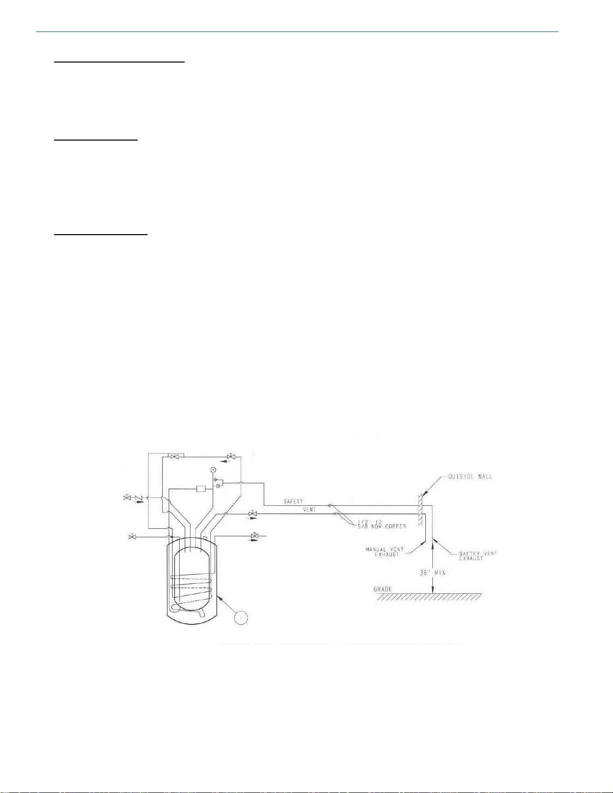
Figure 4 - Internally Sited/Filled Indoors/Pipe Out Safeties
Page 23

Photo 13 - Indoor Installation
InstallationProduct Manual - Perma-Cyl® w/ FlexFill™ Piping Option
Wall Box
Indoor installations allow the tank to be positioned in very
close proximity to the end user’s equipment. This can be
accomplished very easily using a Perma-Cyl Wall Box. The
wall box contains a vent valve, ll line, pressure gauge and
safety pipe out. All connections on the wall box are 1/2”
FPT
Installation of Hoses and Lines
General
Running the liquid ll hose and vent hoses from the ll
box to the tank, will most likely be done differently at each
location By following the basic rules and guidelines listed
below, the lines can be run easily and as simply as possible.
A typical wall box installation is diagrammed below. Note
the guidelines for piping to be used.
19
Indoor Installations
(Inert: Any Size / Oxygen: 230-700L)
Required:
• Room size - Air volume must allow oxygen level to stay
between 18% to 25%
• Increased ventilation
• Valves vented outside (including mobile tanks)
• Oxygen monitors recommended for LAR and LN
Preferred:
• Sealed off away from other work areas
• Ground level next to outside wall
Internally Sited / Filled Indoors / Pipe Out Safeties
Some indoor installations allow for direct lling of the
cylinder because of a close proximity to a doorway. These
installations do not require the use of a wall box but still
need to have safeties vented outside A drain valve should
be included in the safety line. This valve should be operated
periodically to prevent moisture build-up in the line causing
blockage. A 1/2” nominal copper should be used for both
lines. Once through the wall, both lines should be directed
downward and kept a minimum of 36” above the grade.
2
Photo 14 - Line Connection to Fill Box Panel
Line Connection to Fill Box Panel
1 Fasten NPT connection on vent hose to the NPT tting
on the back of the control panel.
2 Fasten NPT connection on ll hose to the NPT tting on
the back of the control panel.
3 Fasten NPT connection on safety vent to the NPT
connection on the back of the wall box
4 Feed all lines back into building while pushing panel
back into the ll box.
5 Loosely fasten panel into box (it will be removed for
pressure checking later).
Page 24

Installation Product Manual - Perma-Cyl® w/ FlexFill™ Piping Option
20
– The length of the line from the tank to the box should
be kept to a minimum. Bare copper line can be used
for lines. If bare copper is used, it should be insulated
using air conditioning foam to keep condensation
from dripping off the piping.
– Line size should be a minimum 5/8” ID
• Vent Line - The vent line should be run using 1/2”
nominal copper or the equivalent size stainless steel
braided hose This line should connect the vent valve in
the wall box to the vent valve on the Perma-Cyl System
Photo 15 - Wall Box
Connections on the wall box are provided for the vent line,
liquid ll and relief line.
• Relief Line - The relief line should be run using 1/2”
nominal copper. Kitec tubing or braided stainless steel
hose can also be used Relief lines should be no smaller
in diameter than the outlet of the relief valve
• Liquid Fill Line - The liquid ll should be piped using
a minimum diameter of 3/4” nominal copper. The
equivalent size stainless steel braided hose can also
be used. The line should be connected from the ll
connection in the wall box to the liquid ll check valve
on the Perma-Cyl System. When piping this line there are
a few guidelines that should be followed
– Bends and elbows should be kept at a minimum.
When needed they should be made with a wide bend
radius A minimum bend radius of 6” should be
Caution! Restrictions in the relief valve
outlet piping should be avoided
to eliminate the possibility
of excessive back pressure
when the relief valve opens.
Restrictions could reduce the
required ow rate of the relief
valve and pose a potential safety
hazard.
observed
Figure 5 - Installation Guideline Schematic
Page 25
InstallationProduct Manual - Perma-Cyl® w/ FlexFill™ Piping Option
21
Bolting to Floor
The Perma-Cyl tank is equipped with a ange on the
bottom that has four holes for attachment To ensure a safe
environment, the tank or pallet base should be bolted to the
oor.
1 Place tank in position with gauges facing forward.
2 Mark holes on oor, move tank.
3 Drill holes using the appropriate size masonry bit.
4 Blow out dust and insert masonry anchors
5 Move tank back into position over holes and install lag
bolts
6 Tighten bolts
Outdoor Installations
(Any Size)
Required:
• Open area
• Well ventilated
• At or above ground level
Photo 16 - Outdoor Installation
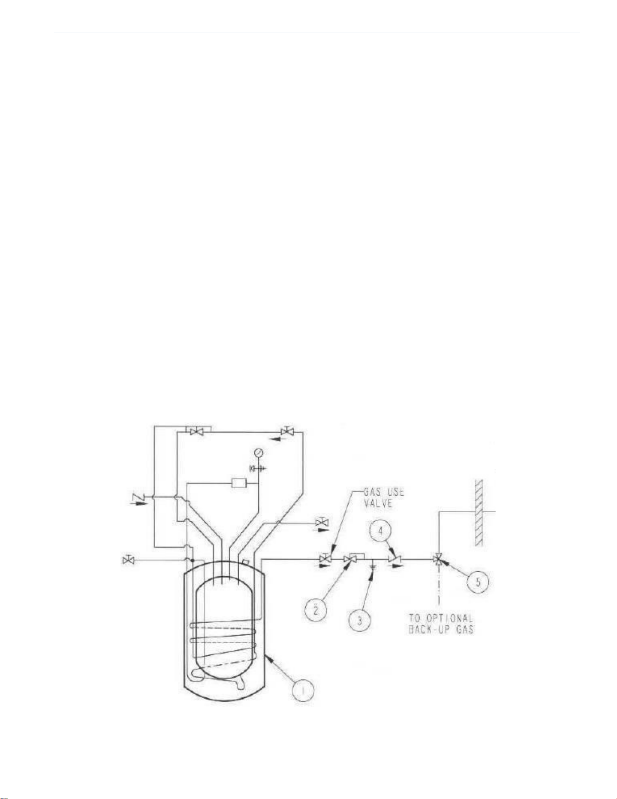
Figure 6 - Externally Sited/Gas Use Installation
Page 26
Installation Product Manual - Perma-Cyl® w/ FlexFill™ Piping Option
22
Externally Sited / Gas Use Indoors
Outdoor installations can offer better accessibility for the
™
Orca
Delivery System for lling purposes. Also, lines
do not need to be run except from the tank to the user’s
equipment. Outdoor installations should be made on a
concrete pad. Local soil conditions and seismic codes will
affect the thickness and reinforcement required for the
concrete pad. The Perma-Cyl unit should be bolted to the
concrete pad using appropriate sized anchor bolts. Also in
outdoor installations, a fence can provide added protection
for the Perma-Cyl system and work to eliminate tampering
with any plumbing component.
Outdoor Installation Schematic
At a minimum, installation should include a nal line
regulator and a check valve. A typical piping schematic is
depicted in Figure 6.
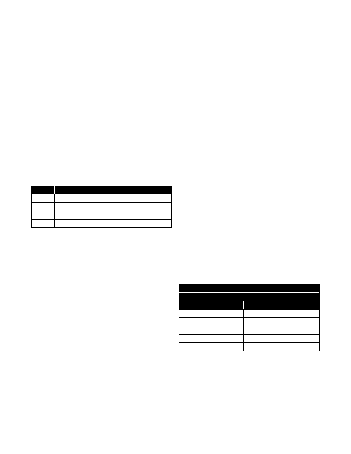
Item # Description
2 Final Line Regulator
3 Safety Relief Valve
4 Check Valve
5 Coupling Valve for optional back up gas supply
First Fill/Purge Procedure
Note: The Perma-Cyl tank is shipped with low
purity nitrogen gas. Purging is necessary
prior to lling. During rst ll, only ll
the vessel to 75% full to allow for liquid
expansion experienced with a new (warm)
tank. Each ll thereafter can be lled to
100% full. All valves on an empty PermaCyl tank should always be kept closed to
prevent the inner vessel and plumbing from
being contaminated.
Purging and First Fill Procedure
1 Attach the source of liquid purge to the ll connection
of the Perma-Cyl tank
2 If the ll hose has not been kept under pressure since
the last delivery, it will need to be purged. Purge the
ll hose and connector through the purge valve, if so
equipped, or by loosening the ll connection until vapor
ows from the connection and then retighten. Use the
hose drain on the tank piping if equipped as such.
3 If the Perma-Cyl tank is pressurized, open the vent
valve and blow down to approximately 5 psi. To prevent
drawing atmospheric contaminants back into the tank
during the purging operation, a positive pressure of at
least 5 psig should be maintained in the tank.
4 Partially ll the Perma-Cyl tank with product according
to the table in the next column
Let liquid build pressure close to safety setting.
Leak check all plumbing circuits while the tank is under
maximum pressure.
While vent gas is still warm and tank is under pressure,
move the four-way valve to the ‘Equalization’ position
and loosen the ttings on either side of the liquid level
gauge to allow the gauge lines to purge with gas. Check
the gas stream coming out of the ttings for evidence of
moisture. Continue to ow the gas until lines have been
purged and there is no visible signs of moisture. Tighten
ttings to stop the ow of gas. Move the four-way valve
to the ‘Normal Operation’ position.
Vent all product out of the liquid valve and close before
pressure drops below 5 psig.
Metered Product per Purge Cycle
Filling Weight Table
Tank Size Product Amount
1000 L Perma-Cyl tank 2000 standard cubic feet
1500 L Perma-Cyl tank 3000 standard cubic feet
2000 L Perma-Cyl tank 4000 standard cubic feet
3000 L Perma-Cyl tank 5000 standard cubic feet
5500 L Perma-Cyl tank 7000 standard cubic feet
5 Fill Perma-Cyl tank with product as indicated in the
table. Primarily use the bottom ll on a FlexFill style
tank. Make sure some product is also routed through
the top ll lines to purge them prior to totally lling the
tank
Page 27

InstallationProduct Manual - Perma-Cyl® w/ FlexFill™ Piping Option
23
Open the PB circuit and set to maximum psi. Ensure
liquid is owing through this circuit as indicated
by frosting on the pipes. Let liquid in the tank build
pressure close to safety setting. Once desired pressure
is reached, open liquid valve. When liquid is out of the
tank and pressure is still high, open the vent and gas use
valves. If a nal line manifold is already connected to
the gas use valve, purge through the manifold to insure
that there is a ow through the gas use circuit and any
moisture is purged out before liquid is introduced into
this circuit
Once pressure is blown down to 5 psig, close the liquid,
vent and gas use valves
6 Fill the Perma-Cyl tank with product and let the liquid
in the tank build pressure close to the safety setting.
Ensure the product is owing through and purging the
economizer lines. Control the pressure by opening the
gas use and vent valves. Once pressure is approximately
5 psig, close the gas use and vent valves.
7 Fill the Perma-Cyl tank with product per the table and
let the liquid in the tank build pressure to close to the
safety setting. Once the desired psig has been reached,
open the gas use and vent valves. Once pressure is
approximately 5 psig, close the gas use and vent valves.
Note: The purge gas should be cooling the tank.
If the tank vent line is HOT, always purge
until the vent line is cool or even frosted.
A new, warm tank should go through a
minimum of four or ve purge cycles before
lling with liquid.
Filling the Tank After the Cool Down Process is Complete
1 If equipped with a bottom ll valve, the bottom ll
valve and the tank vent valve are the valves to be used
to ll a warm tank.
2 Have the driver start the pump and slowly deliver the
liquid into the tank. Observe the tank pressure and
control the pressure by venting the tank down or by
using the top ll valve to control the pressure.
3 As the lling proceeds and the tank gets cooler, you
should be able to pinch off and, in some cases, close the
vent valve. We recommend that you do not ll the tank
to the full trycock on the rst ll. Fill to 75% in order to
allow for liquid expansion as the tank contents absorb
heat while the metal continues to cool down over time
Page 28

Page 29
Product Manual - Perma-Cyl® w/ FlexFill™ Piping Option
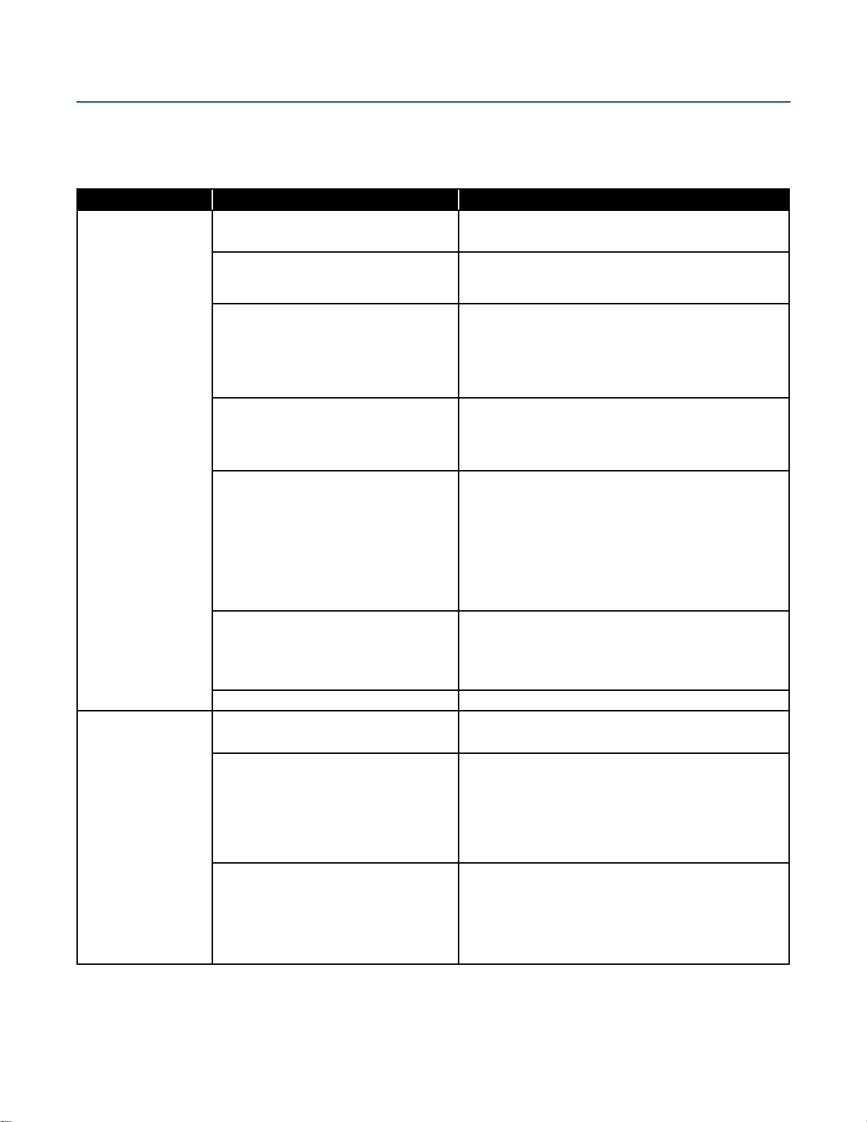
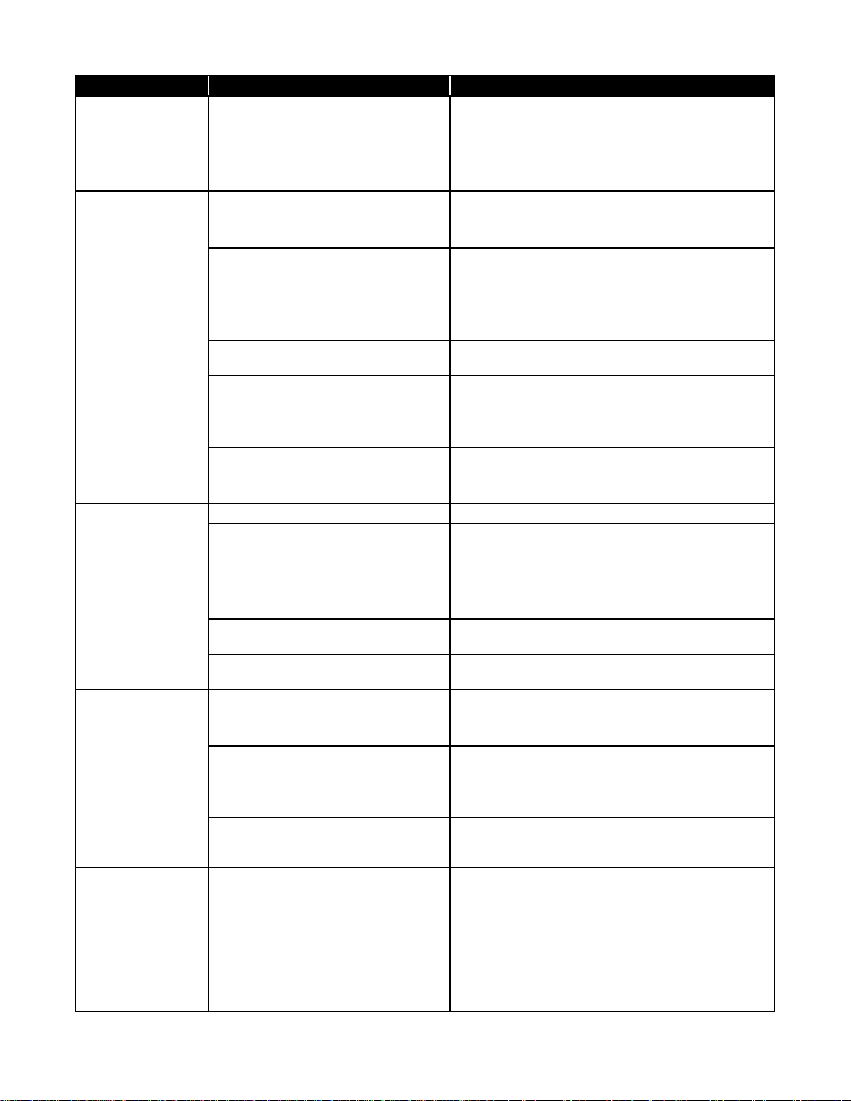
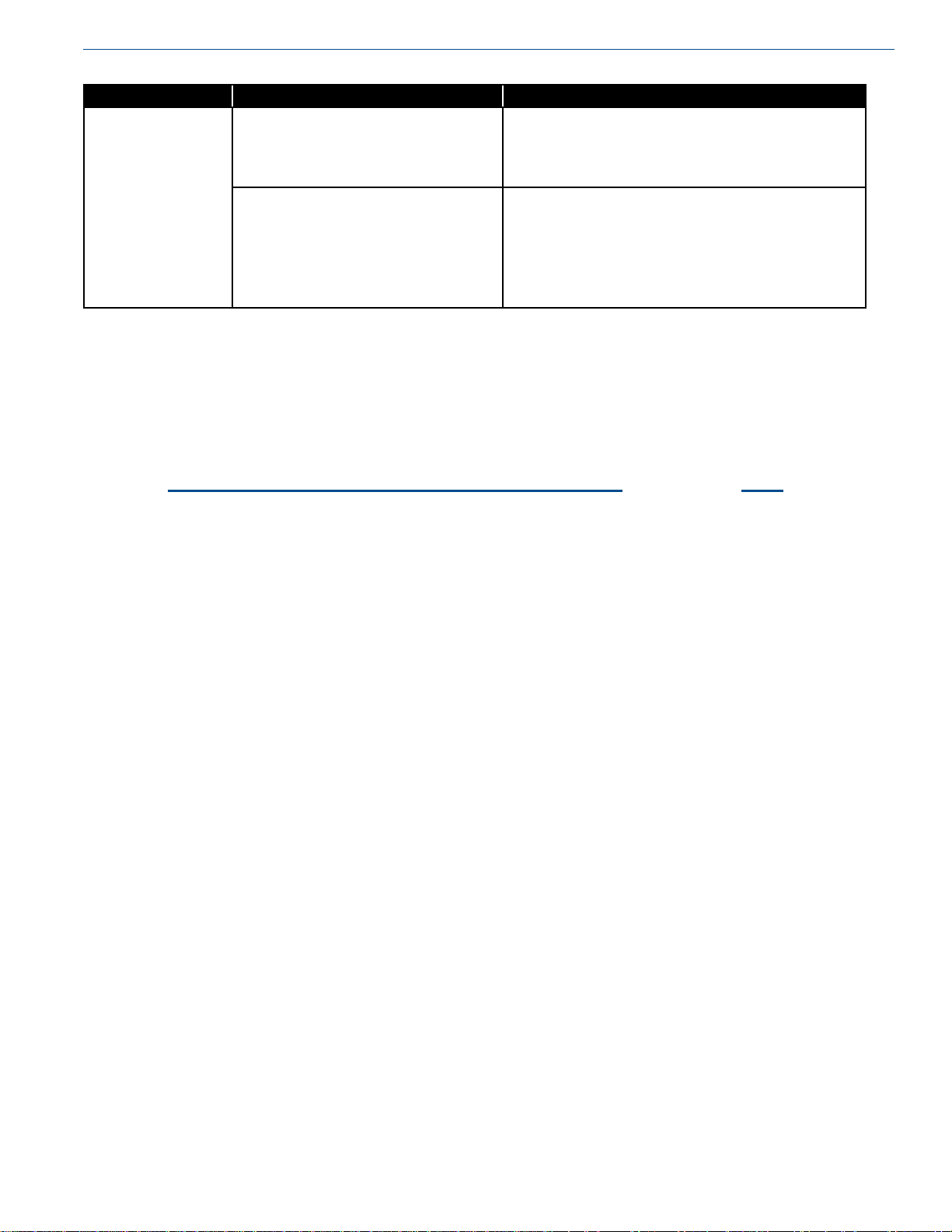
Troubleshooting
The following table is arranged in a Trouble/Probable Cause/Remedy format. The probable causes for specic problems are
listed in descending order of signicance. That is, check out the rst cause listed before proceeding to the next.
Trouble Probable Cause Remedy
No gas to gas-use
equipment.
OR
Insufcient pressure
to gas-use equipment
Frost or ice on sides,
bottom, top-center
and / or plumbing of
tank.
Perma-Cyl tank empty. 1. Switch to emergency gas supply.
2. Call gas supplier for delivery.
Gas-use valve to nal line regulator is
closed or other valves downstream are
closed.
Pressure builder is not building sufcient
pressure.
Final line pressure regulator set too low
or malfunctioning.
Inappropriate type of regulator (highpressure or 2-stage or too small) installed
as nal line regulator and is not able to
supply sufcient gas ow.
Gas supply line, hose, or network
contains excessive pressure drop.
Unknown 1. Call service technician
Normal condition during and following
gas use, liquid use or lling.
Tank is being used for continuous ow
application and is not receiving sufcient
ambient heat to melt the frost or ice.
(Tank may have heavy ice build-up
continuous ice or frost.)
Leak in gas supply lines, gas-use
equipment, or tank plumbing. (Frost is
present on tank even after an extended
period with no gas or liquid use.)
1. Open valve or valves, as needed.
2. Insure there is no obstruction in the line or valve.
1. Open pressure building regulator control valve and
allow pressure to build.
2. Adjust setting on regulator to a higher pressure.
3. If tank pressure fails to rise, see section on low
tank pressure.
1. Ensure gas use valve is open and tank pressure
is at least 25 psi higher than desired working
pressure of nal regulator.
2. Call service technician.
1. Ensure gas use valve is open and tank pressure
is at least 25 psi higher than desired working
pressure of nal regulator.
2. Inspect nal line regulator or its specications to
determine if it has a suitable ow capacity for the
required inlet and outlet pressures.
3. Call appropriate equipment supplier or service
technician.
1. Check line for sufcient diameter.
2. Remove all unnecessary bends, elbows, reducers,
and small diameter valves.
3. Check for leaks in the gas supply line.
1. None
2. User to check tank for frost / leaks before use.
1. Move tank to a warmer location.
2. Add additional environmental heat and / or warm
airow to warm outer piping, components and
sides of the tank.
3. Add switchover system to allow tank to rest and
warm up when not in use.
1. Evacuate and ventilate room.
2. If possible, locate and correct leak,
3. User to check tank for frost / leaks each morning
before starting gas use.
4. Call appropriate equipment service technician.
25
Page 30

Troubleshooting Product Manual - Perma-Cyl® w/ FlexFill™ Piping Option
26
Trouble Probable Cause Remedy
Frost or ice on sides,
bottom, top-center
and / or plumbing of
tank.
(continued)
Routinely low
pressure in tank.
Gas supply to gasuse equipment is too
cold.
Weak vacuum or failed vacuum. 1. Check if tank pressure is routinely high even
during gas use and / or if tank has cold or ice spots
even when not in operation as sign of vacuum
problem.
2. Condensation or sweating is seen over the entire
outer shell as a sign of vacuum problem.
3. Call gas service agent.
Unknown. 1. Call gas service agent.
PB shut-off valve is closed.
(If PB is not operating, no frost ring will
appear at the bottom of the tank or on
external PB vaporizer during gas use.)
Pressure builder setting is too low.
(If PB is not operating, no frost ring will
appear at the bottom of the tank or on
external PB vaporizer during gas use.)
Economizer regulator setting is too low or
economizer regulator is stuck open.
Relief valve(s) stuck open. 1. Evacuate and ventilate the room.
Large gas leak from tank plumbing or
from gas use system.
Gas or liquid withdrawal rate exceeds the
tank specications.
Unknown 1. Switch to emergency gas cylinder.
Ambient temperature surrounding the
Perma-Cyl tank is too cold.
1. Open pressure building regulator control valve and
allow pressure to build.
2. Call service agent to repair, replace or adjust
regulator.
1. Adjust regulator to higher pressure and allow
pressure to build.
2. Call service agent to repair, replace or adjust
regulator.
1. Adjust regulator to higher pressure (should be
at least 15 psig above pressure build regulator
setting).
2. Check to ensure regulator is not stuck open.
2. Check exhaust of relief valve to see if gas is
owing at a pressure below the pressure stamped
on the valve.
3. Tap lightly on the side of the relief valve to attempt
to dislodge any obstruction holding valve open.
Repeat several times, if needed.
4. Call gas service technician to replace relief valve,
if necessary.
1. Evacuate and ventilate the room.
2. If possible, locate and repair leak or call gas
equipment service technician.
1. Excess usage will cause tank pressure to
decrease as PB is unable to maintain pressure.
Decrease withdrawal rate to within design
specications.
2. Increase pressure setting on PB regulator.
3. If withdrawing gas, consider: (a) withdrawing liquid
and using external vaporizer, (b) installing larger
tank, (c) installing additional tank(s), or (d) splitting
application.
4. If withdrawing liquid, consider: (a) installing larger
tank, (b) splitting application or (c) installing
additional tank(s).
5. Call gas service agent.
2. Call gas service technician.
1. Move tank to warmer location.
2. Install freestanding ambient vaporizer on gas
supply line in warmer location or install in-line gas
heater.
Page 31

Trouble Probable Cause Remedy
Gas supply to gasuse equipment is too
cold. (continued)
Routinely high tank
pressure.
Hissing sounds or
evidence of gas
leaking near tank,
gas lines, or gas-use
equipment.
Gas withdrawal rate from Perma-Cyl tank
exceeds the capacity of tank’s ambient
vaporizer.
Normal when little or no gas has been
used for several days.
Economizer function on regulator is
malfunctioning.
Tank is over-lled 1. If tank is lled to or beyond proper ll level,
Pressure building function on
regulator is set too high or regulator is
malfunctioning.
Weak or failed vacuum. 1. Observe if condensation and / or frost are present
Unknown. 1. Call gas service technician.
Normal for short periods of time from
some regulators and relief valves.
1. Reduce gas withdrawal rate to within specied
parameters.
2. Install freestanding ambient vaporizer on gas
supply line in warm location or install in-line heated
vaporizer on gas supply circuit.
3. Install larger tank with greater withdrawal rate
capacity.
1. None - Routine use of gas will automatically
reduce the tank pressure.
2. Gas usage must exceed NER of tank, if not,
contact gas supplier for different tank model.
1. If tank is in a mixer application and the usage is
low, consider drawing gas off the vent line, as
the economizer will not work completely in nonconsistent draws.
2. Call gas service technician to clean, repair, or
replace regulator.
pressure builds very rapidly and relief valve may
open.
2. Use gas or liquid as soon as possible to reduce
tank contents.
3. Vent tank until no liquid is coming out the vent
valve.
1. Reduce pressure setting by turning adjustment
knob counter-clockwise to the desired pressure
setting and continuing normal gas use until
pressure drops.
2. Close PB isolation valve and carefully observe
pressure to ensure tank pressure does not drop
too low during use.
3. Call gas service technician to adjust PB regulator.
even during periods of non-use as possible sign of
vacuum problem.
2. Call gas service technician.
1. Evacuate and ventilate room or area, if necessary.
2. If possible, observe leak. If leak is not large, does
not last long, does not occur frequently and is in
well-ventilated area, no action may be needed.
If in doubt, call appropriate equipment service
technician.
3. If above combined conditions do not exist, call
equipment service technician and observe “Safety”
precautions.
TroubleshootingProduct Manual - Perma-Cyl® w/ FlexFill™ Piping Option
27
Page 32
Troubleshooting Product Manual - Perma-Cyl® w/ FlexFill™ Piping Option
28
Trouble Probable Cause Remedy
Hissing sounds or
evidence of gas
leaking near tank,
gas lines, or gasuse equipment.
Large leaks, leaks from elsewhere in
the system, sustained leaks, or frequent
leaks (not normal).
1. Evacuate all personnel from affected areas.
Ventilate room / area.
2. If possible, locate the leak and repair it or call gas
service or gas-use equipment service technician.
(continued)
High gas usage. Unrecognized increase in actual gas use. 1. None for Perma-Cyl tank or gas supplier
2. Gas user to determine reason for increase in gas
use.
Leak in gas supply line or network or in
gas-use equipment or tank plumbing, e.g.
relief valve.
1. Evacuate and ventilate room, if necessary.
2. If possible, locate and repair leak or call gas-use
equipment service agent.
3. User to check tank for frost / leaks before
operations.
Tank pressure routinely too high and
venting.
High ash or vaporization losses in liquid
use application due to high pressure /
temperature liquid in tank.
1. See troubleshooting section on routinely high tank
pressure.
1. Vent tank to approximately 25 psi. Follow safety
procedures.
2. In future only rell the Perma-Cyl tank with low-
pressure cryogenic product.
Error in gas delivery or supplier invoice. 1. Check gas usage history / pattern against supplier
invoices.
2. Call gas supplier, if necessary.
Perma-Cyl tank
cannot be lled.
Perma-Cyl tank is full. 1. None
Fill line is blocked or inoperative. 1. Check for obstructions in the ll line. Clear if
necessary.
2. Gently tap on check valve to assure proper
operation.
3. Ensure top & bottom ll valves are open.
4. Call gas service technician.
™
MicroBulk Delivery System is not
Orca
1. Refer to Orca system Troubleshooting.
functioning properly.
Perma-Cyl tank does
not initiate automatic
ll shut off properly.
Transfer hose is obstructed, e.g. hose is
bent excessively, crimped or plugged.
Fill line piping created too much pressure
drop.
1. Clean obstruction, inspect hose for damage, and, if
everything is satisfactory, continue the lling.
1. Ensure ll line is piped with 3/4” nominal copper (or
equivalent) with minimal 90° bends.
2. Re-route ll piping.
Improper ll procedure. 1. Review Orca system/Perma-Cyl tank lling
procedure.
2. Ensure that all vent and use valves of the tank are
closed.
Only works with Chart Orca MicroBulk
N/A
delivery vehicle. For other type trucks use
full trycock.
Liquid withdrawal
contains high level
of gas.
Saturated liquid pressure in Perma-Cyl
tank is too high. (Temperature or energy
level of contents is too high due to
excess pressure.)
1. Ensure PB shut-off valve is closed.
2. Open vent valve to allow excess pressure to vent
until desired pressure is obtained. Follow “Safety”
guidelines and procedures for venting.
3. Install secondary lower pressure relief valve to
reduce saturated pressure of liquid in the future.
4. In future only rell the Perma-Cyl tank with low-
pressure cryogenic product.
Page 33
Trouble Probable Cause Remedy
Vacuum pump-out
port and / or vacuum
plug are open or
damaged.
Pump-out plug or port have been
damaged or tampered with.
Inner vacuum space leak has dislodged
safety pump-out plug.
1. If possible, transfer any remaining contents to
another tank.
2. Call gas service technician to replace and repair
tank.
1. If possible, transfer any remaining contents to
another tank.
2. Cover pump out port to keep moisture from getting
into the annular space.
3. Call gas service technician to replace and repair
tank.
Warning! Use only parts which are
cleaned and approved
for oxygen service. Chart
recommends the use of only
Chart approved parts.
TroubleshootingProduct Manual - Perma-Cyl® w/ FlexFill™ Piping Option
29
Page 34

Page 35

Product Manual - Perma-Cyl® w/ FlexFill™ Piping Option
Specications
31
Model
1000L
HP/VHP
Plate
Base
1500L
HP/VHP
Pallet
Base
2000L
HP/VHP
Pallet
Base
3000L
HP/VHP
Pallet
Base
3000L
HP/VHP
Horizontal
Forklift Base
5500L
VHP
Pallet
Base
CAPACITY (Liters)
Gross
Net
1,056
950
1,550
1,455
2,042
1,945
2,911
2,707
2,911
2,707
5,430
5,106
CAPACITY (Gallons)
Gross
Net
279.0
251.0
409.5
384.4
539.5
513.9
770
715
770
715
1,436
1,350
MAWP
psig
barg
350/500
24.1/34.5
350/500
24.1/34.5
350/500
24.1/34.5
350/500
24.1/34.5
350/500
24.1/34.5
500
34.5
MAXIMUM PRE-SET OPERATING PRESSURE
psig
barg
300/450
20.7/31.0
300/450
20.7/31.0
300/450
20.7/31.0
300/450
20.7/31.0
300/450
20.7/31/0
450
31.0
DESIGN SPECIFICATIONS
DOT/ASME ASME ASME ASME ASME ASME ASME
STORAGE CAPACITY
(1)
Nitrogen
SCF
Nm
3
24,350
689
35,790
1,013
47,847
1,257
66,592
1,750
66,592
1,750
125,600
3,560
Oxygen
SCF
Nm
3
30,070
850
44,220
1,250
59,089
1,553
82,239
2,161
82,239
2,161
155,000
4,390
Argon
SCF
3
Nm
THERMAL PERFORMANCE
N
2
O2 - Ar
GAS DELIVERY RATE (LN
SCFH
3
Nm
h
29,400
832
(2)
1%
.62%
/LAR/LOX)
2
960
25.2
(NER%/Day)
43,220
1,223
1%
.62%
1,350
35.4
57,786
1,519
1%
.62%
1,350/2,000
35.4/52.4
(3)
80,425
2,115
1%
.62%
1,350/2,000
35.4/52.4
80,425
2,115
1%
.62%
(3)
2,000
52.4
151,600
4,290
.7%
.43%
3,500/5,000
141
DIMENSIONS
Diameter
Height
Tare Weight
(lbs/kg)
(in/mm) 42 / 1,067 48 / 1,219 48 / 1,219 59 / 1,499 59 / 1,499 80 / 2,030
(in/mm) 82 / 2,083
1,500/1,750*
680/794
92/91 -
2,337/2,311
2,200/2,500**
998/1,134
118.5/119.5 3,010/3,035
2,600/2,950**
1,179/1,338
122/122.5 3,099/3,112
3,300/4,250**
1,497/1,928
71 / 1,803 118 / 3,000
3,800/4,250**
1,724/1,928
8800**
3,998
PALLET BASE DIMENSIONS
Dimensions
All specications are subject to change without prior notice.
1) Values are based on net capacity at 0 psig (0 barg) for ASME vessels.
2) Values are based on gross capacity.
3) Optional 3,500 SCFH (92 Nm3h) ow kit available.
4) Flow rate dependent on process vaporizer option.
All dimensions are measured from the oor to the top of the highest plumbing component.
(in) 46-5/8 x 50-5/8 52-5/8 x 66-5/8 52-5/8 x 66-5/8 60-1/2 x 75-1/2 N/A 101-1/2 x 85-1/2
ASME - American Society of Mechanical Engineers, Section VIII, Division 1
*Weights do not include lab base option. (base option; 265 lbs)
Patents: 6,128,908 • 5,954,101 • 6,799,429
Contact Factory for Canadian Approvals.
**Weights include lab bases.
(4)
Page 36

Page 37

Product Manual - Perma-Cyl® w/ FlexFill™ Piping Option
Illustrations & Parts Listing
1000 HP/VHP FlexFill
33
Page 38

Illustrations & Parts Listing Product Manual - Perma-Cyl® w/ FlexFill™ Piping Option
34
Page 39
Illustrations & Parts ListingProduct Manual - Perma-Cyl® w/ FlexFill™ Piping Option
35
Item PN Description Item PN Description
BD-1 11671281 RPD ASSY INLINE 1/2MPT 375 PSI *RV-2 20894583 RV BRS 1/2MPT 500 PSI
BD-1 11526569 RPD ASSY INLINE 1/2MPT 525 PSI RV-3 1812702 RV BRS 1/4MPT 550 PSI
BD-1 11526622 RPD ASSY INLINE 1/2MPT 700 PSI RV-4 1812702 RV BRS 1/4MPT 550 PSI
CV-1 11051090 VALVE CHECK BRS 1/2FPTX1/2 FPT RV-5 1810702 RV BRS 1/4MPT 550 PSI
Ll-1 20910598 CYL-TEL GEN 5 0-200”H
Ll-1 20923160 DIFF PG 4.5” 0-60” H
Ll-1 20923161 DIFF PG 4.5” 0-60” H
O V-1 10502848 VALVE SHUTOFF BRZ 1/2FPT SHORT
2
O VITON (O2, N2) V-2 11905999 VALVE SHUTOFF 1/4FPT
2
O VITON (AR) V-3 11905999 VALVE SHUTOFF 1/4FPT
2
PI-1 20827654 PG 2-1/2” 0-600PSI/BAR 1/8MPT V-4 11625639 VALVE GLOBE BRS 1/2FPT EX STEM
*R-1 11501177 REGULATOR .250FPT @ 140 PSI V-5 10616790 VALVE GLOBE BRS 1/2NPT SCRD
*R-1 20885664 REGULATOR .250FPT @ 325 PSI V-6 10616790 VALVE GLOBE BRS 1/2NPT SCRD
*R-1 10619675 REGULATOR .250NPT @ 475 PSI V-7 10907239 VALVE NEEDLE BRS 1/4MPT(ANGLE)
*R-2 2110032 REGULATOR .250FPT @ 125 PSI V-8 11773885 VALVE BALL DIV SS 1/2NPT
*R-2 2110742 REGULATOR .250FPT @ 300 PSI V-9 11905956 VALVE BRS SH 3/8FPTX3/8 SCH 10
*R-2 10619667 REGULATOR .250NPT @ 450 PSI V-10 11905999 VALVE SHUTOFF 1/4FPT
RV-1 1812702 RV BRS 1/4MPT 550 PSI V-11 20683719 VALVE 4-WAY BRS 1/8 FPT
*RV-2 11488574 RV BRS 1/2MPT 250 PSI V-12 11905999 VALVE SHUTOFF 1/4FPT
*RV-2 20599868 RV BRS 1/2MPT 350 PSI V-13 11905999 VALVE SHUTOFF 1/4FPT
*Part numbers are dependent on the plumbing option kit chosen for the vessel.
Page 40

Illustrations & Parts Listing Product Manual - Perma-Cyl® w/ FlexFill™ Piping Option
36
1500 HP/VHP FlexFill
Page 41

Illustrations & Parts ListingProduct Manual - Perma-Cyl® w/ FlexFill™ Piping Option
37
Page 42
Illustrations & Parts Listing Product Manual - Perma-Cyl® w/ FlexFill™ Piping Option
38
Item PN Description Item PN Description
*BD-1 11671281 RPD ASSY INLINE 1/2MPT 375 PSI *RV-2 20894583 RV BRS 1/2MPT 500 PSI
*BD-1 11526569 RPD ASSY INLINE 1/2MPT 525 PSI RV-3 1812702 RV BRS 1/4MPT 550 PSI
*BD-1 11526622 RPD ASSY INLINE 1/2MPT 700 PSI RV-4 1812702 RV BRS 1/4MPT 550 PSI
CV-1 11051090 VALVE CHECK BRS 1/2FPTX1/2 FPT RV-5 1810702 RV BRS 1/4MPT 550 PSI
*Ll-1 20910598 CYL-TEL GEN 5 0-200”H
*Ll-1 20923162 DIFF PG 4.5” 0-100” H
N2)
*Ll-1 20909588 DIFF PG 4.5” 0-150” H
O V-1 10502848 VALVE SHUTOFF BRZ 1/2FPT SHORT
2
O VITON (O2,
2
O VITON (Ar) V-3 11905999 VALVE SHUTOFF 1/4FPT
2
V-2 11905999 VALVE SHUTOFF 1/4FPT
PI-1 20827654 PG 2-1/2” 0-600PSI/BAR 1/8MPT V-4 11625639 VALVE GLOBE BRS 1/2FPT EX STEM
*R-1 11501177 REGULATOR .250FPT @ 140 PSI V-5 10616790 VALVE GLOBE BRS 1/2NPT SCRD
*R-1 20885664 REGULATOR .250FPT @ 325 PSI V-6 10616790 VALVE GLOBE BRS 1/2NPT SCRD
*R-1 10619675 REGULATOR .250NPT @ 475 PSI V-7 10907239 VALVE NEEDLE BRS 1/4MPT(ANGLE)
*R-2 2110032 REGULATOR .250FPT @ 125 PSI V-8 11773885 VALVE BALL DIV SS 1/2NPT
*R-2 2110742 REGULATOR .250FPT @ 300 PSI V-9 11905956 VALVE BRS SH 3/8FPTX3/8 SCH 10
*R-2 10619667 REGULATOR .250NPT @ 450 PSI V-10 11905999 VALVE SHUTOFF 1/4FPT
RV-1 1812702 RV BRS 1/4MPT 550 PSI V-11 20683719 VALVE 4-WAY BRS 1/8 FPT
*RV-2 11488574 RV BRS 1/2MPT 250 PSI V-12 11905999 VALVE SHUTOFF 1/4FPT
*RV-2 20599868 RV BRS 1/2MPT 350 PSI V-13 11905999 VALVE SHUTOFF 1/4FPT
*Part numbers are dependent on the plumbing option kit chosen for the vessel.
Page 43

2000 HP FlexFill
Illustrations & Parts ListingProduct Manual - Perma-Cyl® w/ FlexFill™ Piping Option
39
Page 44

Illustrations & Parts Listing Product Manual - Perma-Cyl® w/ FlexFill™ Piping Option
40
Page 45
Illustrations & Parts ListingProduct Manual - Perma-Cyl® w/ FlexFill™ Piping Option
41
Item PN Description Item PN Description
BD-1 11671281 RPD ASSY INLINE 1/2MPT 375 PSI RV-4 1812702 RV BRS 1/4MPT 550 PSI
BD-1 11526569 RPD ASSY INLINE 1/2MPT 525 PSI RV-5 1810702 RV BRS 1/4MPT 550 PSI
CV-1 11051090 VALVE CHECK BRS 1/2FPTX1/2 FPT V-1 10502848 VALVE SHUTOFF BRZ 1/2FPT SHORT
Ll-1 20910598 CYL-TEL GEN 5 0-200”H
Ll-1 20923162 DIFF PG 4.5” 0-100” H
N2)
Ll-1 20909588 DIFF PG 4.5” 0-150” H
O V-2 11905999 VALVE SHUTOFF 1/4FPT
2
O VITON (O2,
2
O VITON (Ar) V-4 11625639 VALVE GLOBE BRS 1/2FPT EX STEM
2
V-3 11905999 VALVE SHUTOFF 1/4FPT
PI-1 20827654 PG 2-1/2” 0-600PSI/BAR 1/8MPT V-5 10616790 VALVE GLOBE BRS 1/2NPT SCRD
*R-1 11501177 REGULATOR .250FPT @ 140 PSI V-6 10616790 VALVE GLOBE BRS 1/2NPT SCRD
*R-1 20885664 REGULATOR .250FPT @ 325 PSI V-7 10907239 VALVE NEEDLE BRS 1/4MPT(ANGLE)
*R-2 11779806 REGULATOR .500FPT @ 125 PSI V-8 11773885 VALVE BALL DIV SS 1/2NPT
*R-2 11690211 REGULATOR .500FPT @ 300 PSI V-9 11905956 VALVE BRS SH 3/8FPTX3/8 SCH 10
RV-1 1812702 RV BRS 1/4MPT 550 PSI V-10 11905999 VALVE SHUTOFF 1/4FPT
*RV-2 11488574 RV BRS 1/2MPT 250 PSI V-11 20683719 VALVE 4-WAY BRS 1/8 FPT
*RV-2 20599868 RV BRS 1/2MPT 350 PSI V-12 11905999 VALVE SHUTOFF 1/4FPT
RV-3 1812702 RV BRS 1/4MPT 550 PSI V-13 11905999 VALVE SHUTOFF 1/4FPT
*Part numbers are dependent on the plumbing option kit chosen for the vessel.
Page 46

Illustrations & Parts Listing Product Manual - Perma-Cyl® w/ FlexFill™ Piping Option
42
3000 HP FlexFill
Page 47

Illustrations & Parts ListingProduct Manual - Perma-Cyl® w/ FlexFill™ Piping Option
43
Page 48
Illustrations & Parts Listing Product Manual - Perma-Cyl® w/ FlexFill™ Piping Option
44
Item PN Description Item PN Description
BD-1 11671281 RPD ASSY INLINE 1/2MPT 375 PSI RV-4 1812702 RV BRS 1/4MPT 550 PSI
BD-1 11526569 RPD ASSY INLINE 1/2MPT 525 PSI RV-5 1810702 RV BRS 1/4MPT 550 PSI
CV-1 11051090 VALVE CHECK BRS 1/2FPTX1/2 FPT V-1 10502848 VALVE SHUTOFF BRZ 1/2FPT SHORT
Ll-1 20910598 CYL-TEL GEN 5 0-200”H
Ll-1 20923162 DIFF PG 4.5” 0-100” H
N2)
Ll-1 20909588 DIFF PG 4.5” 0-150” H
O V-2 11905999 VALVE SHUTOFF 1/4FPT
2
O VITON (O2,
2
O VITON (Ar) V-4 11625639 VALVE GLOBE BRS 1/2FPT EX STEM
2
V-3 11905999 VALVE SHUTOFF 1/4FPT
PI-1 20827654 PG 2-1/2” 0-600PSI/BAR 1/8MPT V-5 10616790 VALVE GLOBE BRS 1/2NPT SCRD
*R-1 11501177 REGULATOR .250FPT @ 140 PSI V-6 10616790 VALVE GLOBE BRS 1/2NPT SCRD
*R-1 20885664 REGULATOR .250FPT @ 325 PSI V-7 10907239 VALVE NEEDLE BRS 1/4MPT(ANGLE)
*R-2 11779806 REGULATOR .500FPT @ 125 PSI V-8 11773885 VALVE BALL DIV SS 1/2NPT
*R-2 11690211 REGULATOR .500FPT @ 300 PSI V-9 11905956 VALVE BRS SH 3/8FPTX3/8 SCH 10
RV-1 1812702 RV BRS 1/4MPT 550 PSI V-10 11905999 VALVE SHUTOFF 1/4FPT
*RV-2 11488574 RV BRS 1/2MPT 250 PSI V-11 20683719 VALVE 4-WAY BRS 1/8 FPT
*RV-2 20599868 RV BRS 1/2MPT 350 PSI V-12 11905999 VALVE SHUTOFF 1/4FPT
RV-3 1812702 RV BRS 1/4MPT 550 PSI V-13 11905999 VALVE SHUTOFF 1/4FPT
*Part numbers are dependent on the plumbing option kit chosen for the vessel.
Page 49

2000 VHP FlexFill
Illustrations & Parts ListingProduct Manual - Perma-Cyl® w/ FlexFill™ Piping Option
45
Page 50

Illustrations & Parts Listing Product Manual - Perma-Cyl® w/ FlexFill™ Piping Option
46
Page 51
Illustrations & Parts ListingProduct Manual - Perma-Cyl® w/ FlexFill™ Piping Option
47
Item PN Description Item PN Description
BD-1 11671281 RPD ASSY INLINE 1/2MPT 375 PSI *RV-2 20599868 RV BRS 1/2MPT 350 PSI
BD-1 11526569 RPD ASSY INLINE 1/2MPT 525 PSI *RV-2 20894583 RV BRS 1/2MPT 500 PSI
BD-1 11526622 RPD ASSY INLINE 1/2MPT 700 PSI RV-3 1812702 RV BRS 1/4MPT 550 PSI
CV-1 11051090 VALVE CHECK BRS 1/2FPTX1/2 FPT S-1 11529090 STRAINER .500NPT BRZ BODY
CV-2 13462175 KIT CHECK VALVE NIBCO 1/2”FPT V-1 10502848 VALVE SHUTOFF BRZ 1/2FPT SHORT
CV-3 11656072 VALVE CHECK BRS FPT V-2 1712202 VALVE BALL BRS 1/2FPT
CV-4 13620233 VALVE CHECK BRS 1/2FPTX1/2FPT V-3 11905999 VALVE SHUTOFF 1/4FPT
*Ll-1 20910598 CYL-TEL GEN 5 0-200”H
*Ll-1 20923162 DIFF PG 4.5” 0-100” H
)
N
2
*Ll-1 20909588 DIFF PG 4.5” 0-150” H
O V-4 11625639 VALVE GLOBE BRS 1/2FPT EX STEM
2
O VITON (O2,
2
O VITON (Ar) V-6 10616790 VALVE GLOBE BRS 1/2NPT SCRD
2
V-5 10616790 VALVE GLOBE BRS 1/2NPT SCRD
PI-1 20827654 PG 2-1/2” 0-600PSI/BAR 1/8MPT V-7 10907239 VALVE NEEDLE BRS 1/4MPT(ANGLE)
*R-1 11779806 REGULATOR .500FPT @ 125 PSI V-8 11773885 VALVE BALL DIV SS 1/2NPT
*R-1 11690211 REGULATOR .500FPT @ 300 PSI V-9 11905956 VALVE BRS SH 3/8FPTX3/8 SCH 10
*R-1 11635511 REGULATOR .500NPT @ 450 PSI V-10 11905999 VALVE SHUTOFF 1/4FPT
RV-1 1812702 RV BRS 1/4MPT 550 PSI V-11 20683719 VALVE 4-WAY BRS 1/8 FPT
*RV-2 11488574 RV BRS 1/2MPT 250 PSI
*Part numbers are dependent on the plumbing option kit chosen for the vessel.
Page 52

Illustrations & Parts Listing Product Manual - Perma-Cyl® w/ FlexFill™ Piping Option
48
3000 VHP FlexFill
Page 53

Illustrations & Parts ListingProduct Manual - Perma-Cyl® w/ FlexFill™ Piping Option
49
Page 54
Illustrations & Parts Listing Product Manual - Perma-Cyl® w/ FlexFill™ Piping Option
50
Item PN Description Item PN Description
BD-1 11671281 RPD ASSY INLINE 1/2MPT 375 PSI *RV-2 20599868 RV BRS 1/2MPT 350 PSI
BD-1 11526569 RPD ASSY INLINE 1/2MPT 525 PSI *RV-2 20894583 RV BRS 1/2MPT 500 PSI
BD-1 11526622 RPD ASSY INLINE 1/2MPT 700 PSI RV-3 1812702 RV BRS 1/4MPT 550 PSI
CV-1 11051090 VALVE CHECK BRS 1/2FPTX1/2 FPT S-1 11529090 STRAINER .500NPT BRZ BODY
CV-2 13462175 KIT CHECK VALVE NIBCO 1/2”FPT V-1 10502848 VALVE SHUTOFF BRZ 1/2FPT SHORT
CV-3 11656072 VALVE CHECK BRS FPT V-2 11905999 VALVE SHUTOFF 1/4FPT
CV-4 13620233 VALVE CHECK BRS 1/2FPTX1/2FPT V-3 11905999 VALVE SHUTOFF 1/4FPT
*Ll-1 20786602 CYL-TEL GEN 5 BACK 0-200”H
*Ll-1 20923162 DIFF PG 4.5” 0-100” H
N2)
*Ll-1 20909588 DIFF PG 4.5” 0-150” H
O VITON (O2,
2
O VITON (Ar) V-6 10616790 VALVE GLOBE BRS 1/2NPT SCRD
2
O V-4 11625639 VALVE GLOBE BRS 1/2FPT EX STEM
2
V-5 10616790 VALVE GLOBE BRS 1/2NPT SCRD
PI-1 20827654 PG 2-1/2” 0-600PSI/BAR 1/8MPT V-7 10907239 VALVE NEEDLE BRS 1/4MPT(ANGLE)
*R-1 11779806 REGULATOR .500FPT @ 125 PSI V-8 11773885 VALVE BALL DIV SS 1/2NPT
*R-1 11690211 REGULATOR .500FPT @ 300 PSI V-9 11905956 VALVE BRS SH 3/8FPTX3/8 SCH 10
*R-1 11635511 REGULATOR .500NPT @ 450 PSI V-10 11905999 VALVE SHUTOFF 1/4FPT
RV-1 1812702 RV BRS 1/4MPT 550 PSI V-11 20683719 VALVE 4-WAY BRS 1/8 FPT
*RV-2 11488574 RV BRS 1/2MPT 250 PSI
*Part numbers are dependent on the plumbing option kit chosen for the vessel.
Page 55
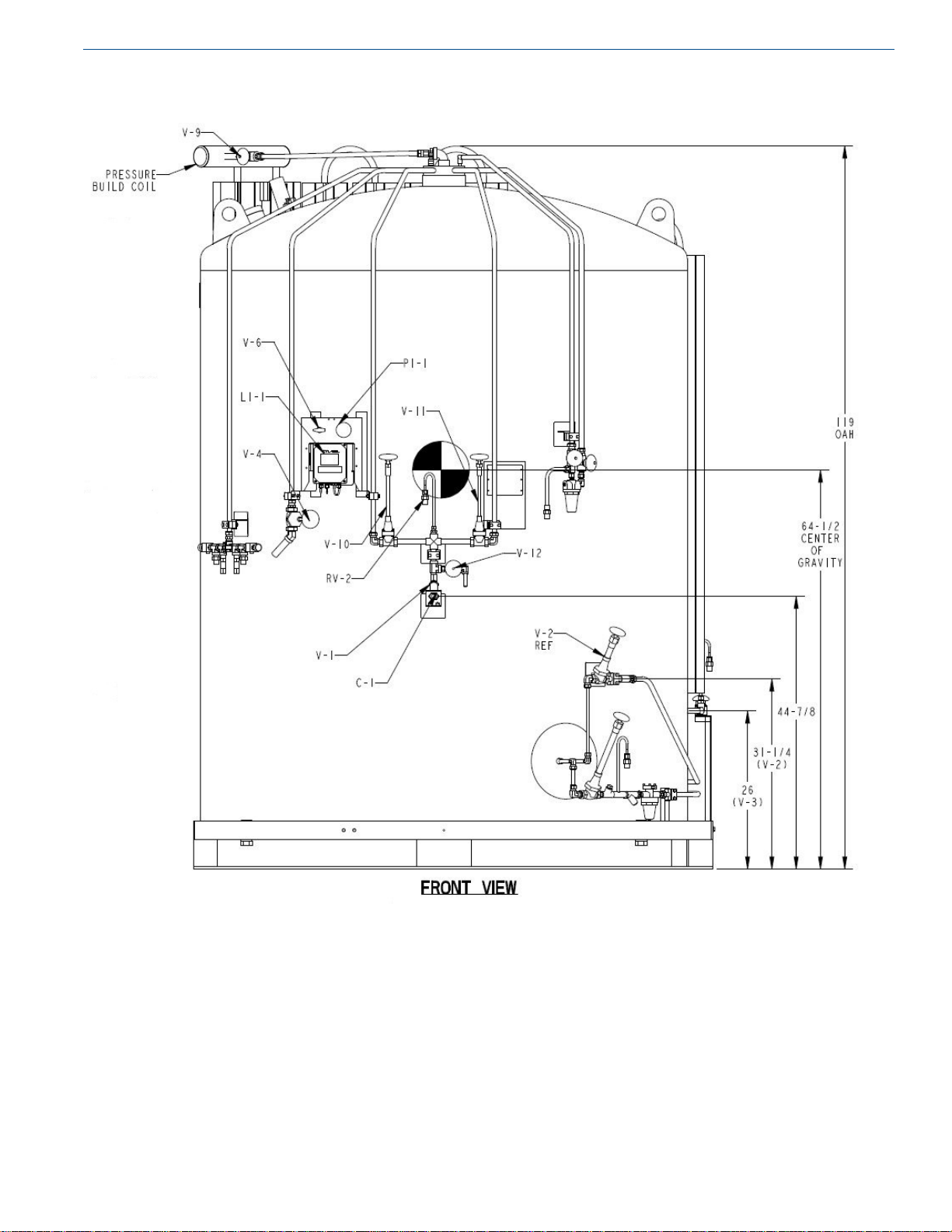
5500 VHP FlexFill
Illustrations & Parts ListingProduct Manual - Perma-Cyl® w/ FlexFill™ Piping Option
51
Page 56
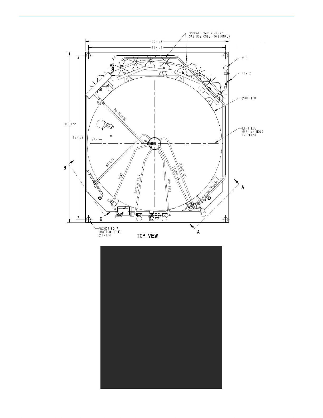
Illustrations & Parts Listing Product Manual - Perma-Cyl® w/ FlexFill™ Piping Option
52
Page 57
Illustrations & Parts ListingProduct Manual - Perma-Cyl® w/ FlexFill™ Piping Option
53
Item PN Description Item PN Description
V-1 11051090 VALVE CHECK BRS 1/2FPTX1/2FPT *R-1 11635511 REGULATOR .500NPT @ 450 PSI
V-2 1718802 VALVE GLOBE BRS 1/2NPT *R-2 20934785 REGULATOR .250NPT @ 140 PSI
*V-3 10502848 VALVE SHUTOFF BRZ 1/2FPT SHORT *R-2 20934016 REGULATOR .250NPT @ 315 PSI
V-4 10540334 VALVE GLOBE BRS 3/4NPT SCRD *R-2 20905985 REGULATOR .250NPT @ 465 PSI
V-5 1713202 VALVE SHUTOFF 3/8 FPT *RV-1 11488574 RV BRS 1/2MPT 250 PSI
V-6 20683719 VALVE 4-WAY BRS 1/8FPT *RV-1 20599868 RV BRS 1/2MPT 350 PSI
V-7 1713202 VALVE SHUTOFF 3/8 FPT *RV-1 20894583 RV BRS 1/2MPT 500 PSI
V-8 1718802 VALVE GLOBE BRS 1/2NPT RV-2 1812702 RV BRS 1/4MPT 550 PSI
V-9 10502848 VALVE SHUTOFF BRZ 1/2FPT SHORT S-1 11529090 STRAINER .500NPT BRZ BODY
V-10 20915798 VALVE GLOBE BRZ 1/2NPT PI-1 20827654 PG 2-1/2” 0-600 PSI/BAR 1/8MPT
V-11 20915798 VALVE GLOBE BRZ 1/2NPT *LI-1 20786602 CYL-TEL GEN 4 BACK 0-200”H
V-12 11905999 VALVE SHUTOFF 1/4FPT *LI-1 20923162 DIFF PG 4.5” 0-100” H
N2)
V-13 11773885 VALVE BALL DIV SS 1/2 NPT *LI-1 20909588 DIFF PG 4.5” 0-150” H
O VITON (O2,
2
O VITON (Ar)
2
V-14 10907239 VALVE NEEDLE BRS 1/4MPT (ANGLE) BD-1 11526622 RPD ASSY INLINE 1/2MPT 700 PSI
*R-1 11779806 REGULATOR .500NPT @ 125 PSI VP-1 -- VACUUM PUMPOUT PORT
*R-1 11690211 REGULATOR .500NPT @ 300 PSI C-2 1210642 TEE BRS 1/2FPT MACHINED
*Part numbers are dependent on the plumbing option kit chosen for the vessel.
O
2
Page 58
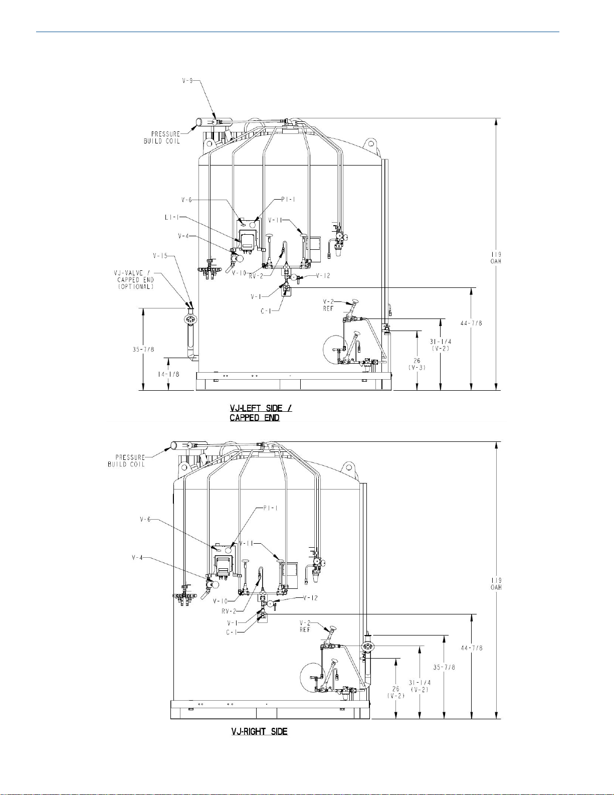
Illustrations & Parts Listing Product Manual - Perma-Cyl® w/ FlexFill™ Piping Option
54
5500 MP FlexFill
Page 59
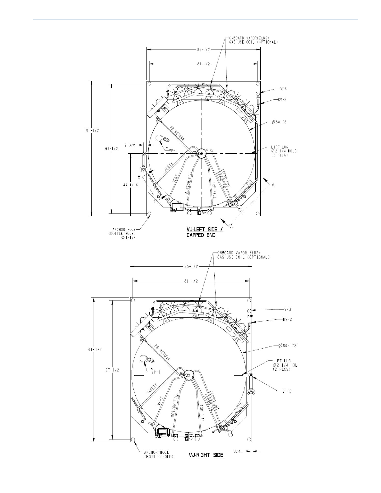
Illustrations & Parts ListingProduct Manual - Perma-Cyl® w/ FlexFill™ Piping Option
55
Page 60
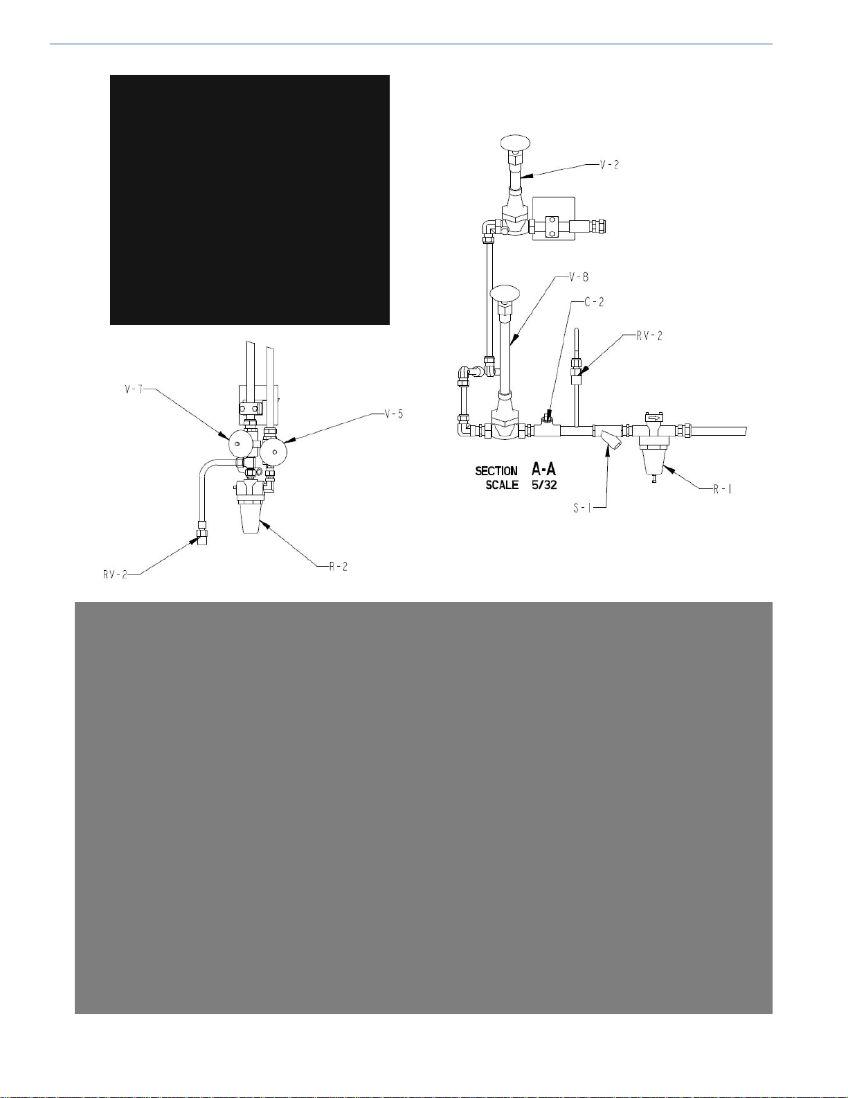
Illustrations & Parts Listing Product Manual - Perma-Cyl® w/ FlexFill™ Piping Option
56
Page 61
Illustrations & Parts ListingProduct Manual - Perma-Cyl® w/ FlexFill™ Piping Option
Item PN Description Item PN Description
V-1 11051090 VALVE CHECK BRS 1/2FPTX1/2FPT *R-1 11779806 REGULATOR .500NPT @ 125 PSI
V-2 1718802 VALVE GLOBE BRS 1/2NPT *R-2 21029469 REGULATOR .250NPT @ 50 PSI
*V-3 10502848 VALVE SHUTOFF BRZ 1/2FPT SHORT *R-2 20934785 REGULATOR .250NPT @ 140 PSI
V-4 10540334 VALVE GLOBE BRS 3/4NPT SCRD *RV-1 20996153 RV BRS 1/2MPT 150 PSI
V-5 1713202 VALVE SHUTOFF 3/8 FPT *RV-1 11488574 RV BRS 1/2MPT 250 PSI
V-6 20683719 VALVE 4-WAY BRS 1/8FPT RV-2 1812702 RV BRS 1/4MPT 550 PSI
V-7 1713202 VALVE SHUTOFF 3/8 FPT S-1 11529090 STRAINER .500NPT BRZ BODY
V-8 10616790 VALVE GLOBE BRS 1/2NPT PI-1 20827654 PG 2-1/2” 0-600 PSI/BAR 1/8MPT
V-9 10502848 VALVE SHUTOFF BRZ 1/2FPT SHORT *LI-1 20786602 CYL-TEL GEN 4 BACK 0-200”H
V-10 20915798 VALVE GLOBE BRZ 1/2NPT *LI-1 20923162 DIFF PG 4.5” 0-100” H
N2)
V-11 20915798 VALVE GLOBE BRZ 1/2NPT *LI-1 20909588 DIFF PG 4.5” 0-150” H
O VITON (O2,
2
O VITON (Ar)
2
V-12 11905999 VALVE SHUTOFF 1/4FPT BD-1 11519668 RPD ASSY INLINE 3/8 FPT 375 PSI
V-13 11773885 VALVE BALL DIV SS 1/2 NPT VP-1 -- VACUUM PUMPOUT PORT
V-14 10907239 VALVE NEEDLE BRS 1/4MPT (ANGLE) C-1 -- FILL CONNECTION
V-15 87-2542-
VALVE Y-PATTERN VJ-1/2” NPS C-2 -- LIQUID WITHDRAWAL CONNECTION
05011
*R-1 20760715 REGULATOR .500NPT @ 35 PSI
*Part numbers are dependent on the plumbing option kit chosen for the vessel.
57
O
2
Page 62

Page 63

Product Manual - Perma-Cyl® w/ FlexFill™ Piping Option
Warranty
Warranty only applies to original purchaser of Chart
equipment and does not transfer to any other party.
Materials, components and workmanship are warranted to be
free of defects for 90 days from date of invoice
Vacuum integrity as measured by conformance to Chart NER
(Normal Evaporation Rate) specications is warranted as
follows:
• Perma-Cyl, liquid cylinders - 5 years from date of
invoice
• All Chart repaired liquid cylinders - 2 years from date of
invoice
Damage or abuse caused by purchaser voids Chart warranty
obligations
Freight damage incurred during shipment from Chart to
purchaser must be reported immediately to Chart, and before
placing equipment into service.
59
In the event of a valid warranty claim, Chart reserves the
right to repair, replace or refund the value of the equipment
at its discretion. The warranty applies only to the purchased
Chart equipment and in no case is Chart obligated to
reimburse the purchaser for consequential damages resulting
from the operation of Chart equipment.
Page 64

 Loading...