

Page 1

IT
USER MANUAL
CONSTELLATION
Page 2

2
USER MANUAL
ENGLISH
Page 3

3
EN
/INDEX/
ASSEMBLY
page 4
CONNECTION CABLE
page 5
ELECTRICAL CONNECTION
page 6
AMPLIFIER
page 8
LISTENING ROOM
page 9
SPEAKER POSITIONING
page 10
STRAY MAGNENITC FIELDS
page 12
MAINTANCE AND WARRENTIES
page 13
STAND ASSEMBLY
page 14
Page 4

4
Assembly/
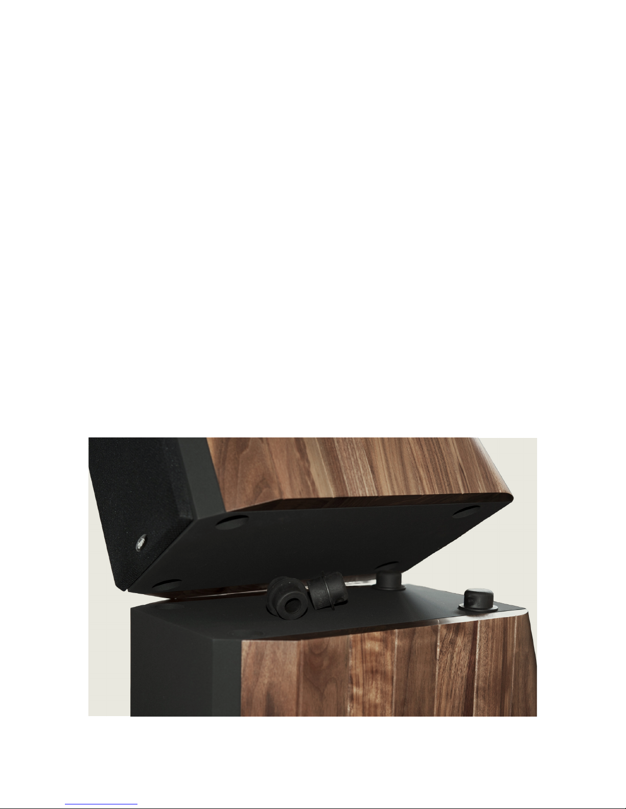
Only for Ursa Major model.
Place the 4 supplied dampers into the slot on the lower part of the
speaker and carefully place the top until full contact of the two parts.
Page 5
5
EN
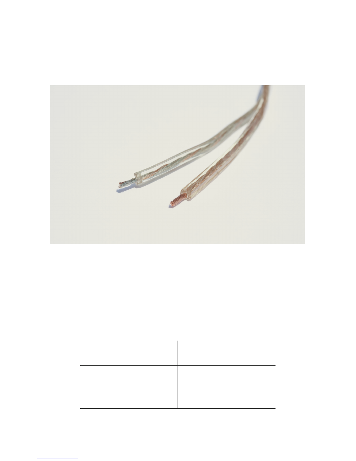
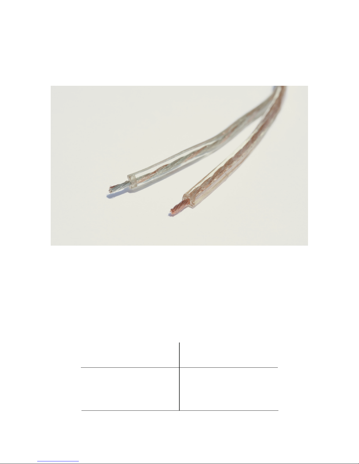
The best connection is obtained by using short lengths of board
cables. The cables should always be the bipolar-multithread type (in
no case should rigid single thread cable be used), preferably board,
such as the cables for hi-fi connections normally available in the
specialized shops. For those who wish to use ordinary electric wire, it
is advisable to keep to the following minimum requisites:
Connection Cable/
Distance
Amplifier/Speaker
Up to 5 meters
From 5 to 10 meters
Over 10 meters
Minimum Cable
Cross Section
0,75 sq. mm
1.00 sq. mm
2.00 sq. mm
Page 6

6
Electrical
Connection/
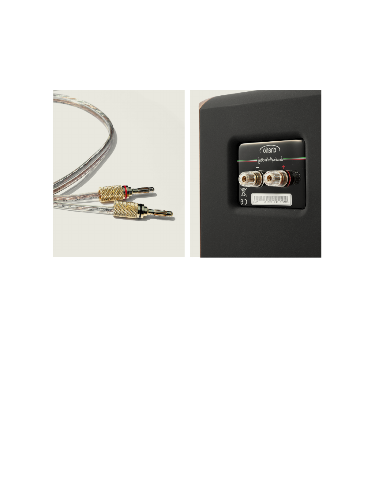
All connections should be made with the audio equipment
switched off.
The amplifier terminals are marked: red for the positive pole and
black for the negative. The input terminals of Chario speakers are
clearly marked with the indications + for the positive and – for the
negative inputs.
While connecting the amplifier to the speakers great care should be
taken not to confuse the polarities.
Page 7

7
EN
Electrical
Connection/
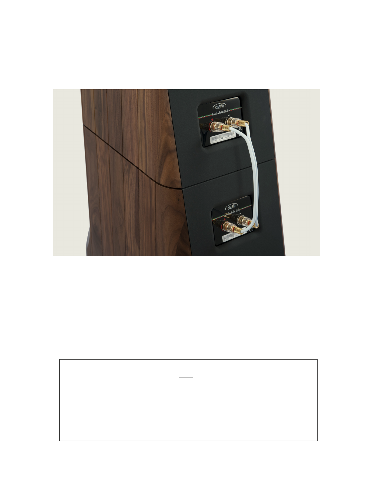
For Ursa Major model use the supplied cable to connect
the low to the high part.
Ursa Major model can be also connected in bi-wiring or bi-amping.
N.B.
Inversion of the polarities will NOT damage the
speakers in any way. The quality of the sound will,
however, be impaired (with a considerable loss of the
power), and therefore the stereo image will be altered
with a difficult location of the sources.
Page 8

8
It is possible to use more powerful amplifiers than those suggested:
in this case, however it is necessary to be careful when regulating the
volume in order to avoid the speakers damage by sending them a too
powerful signal.
It is also advisable, if using a low powered amplifier, not to keep the
volume switch at the maximum level (especially if the tone controls
are changed) on order to avoid serious damage to the tweeters.
Generally, the recommended power amplifier has to be directly
proportional to the size of the listening room. It should have a
minimum electrical power of 1W each cubic meter. The power amplifier
is suitable for an impedance of 4 ohm.
For connections between source and amplifier, refer to the manuals
supplied with the devices.
Amplifiers/
Page 9

9
EN
The environment have a fundamental importance to determinate the
quality of listening. The shape of the room , ornaments, furniture,
upholstery, curtaining, carpets, glasses and anything else do
determine the sonic performance of your living room.
The room should therefore be optimized by moving the furniture and
"calibrating” the reflecting and absorbing surfaces, in order to obtain
as much “acoustic neutrality” as possible.
To increase the performance of the room please contact acoustic
specialists for home entertainment.
Listening Room/
Page 10
10
1,5 m
1 m
0,5 m
0,5 m
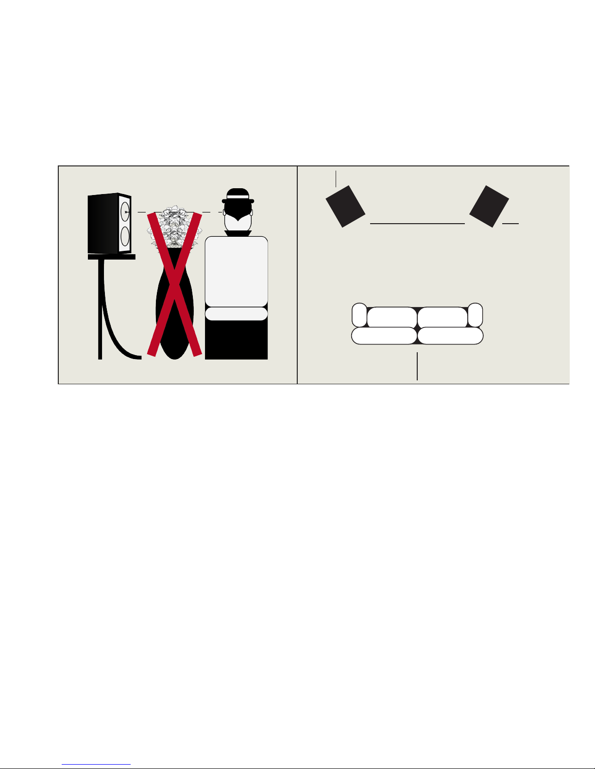
Once your room has been
optimized, it is necessary to
find the right position for
the speakers within it. Also
in this case (because of the
variety of possible solutions)
it is advisable to proceed
by tries, experimenting the
different positions, but always
remembering that:
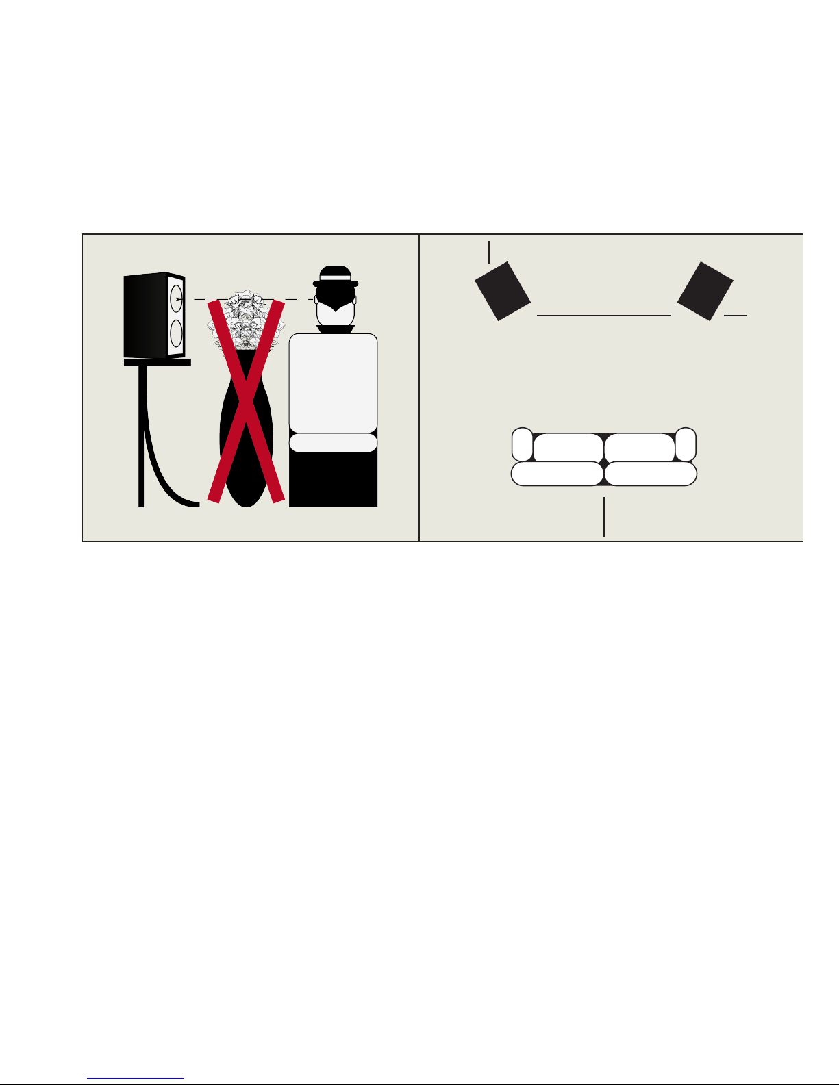
- There should not be any bulky
object between the speakers and
the listener.
Speaker
Positioning/
- There should be at least 1
meter between the listener and
the wall behind him.
- To optimize the distance
between speakers increase
the distance between them
gradually, until you’ll hear a
"hole in the middle": that’s the
allowed maximum distance, so
just reduce it a bit.
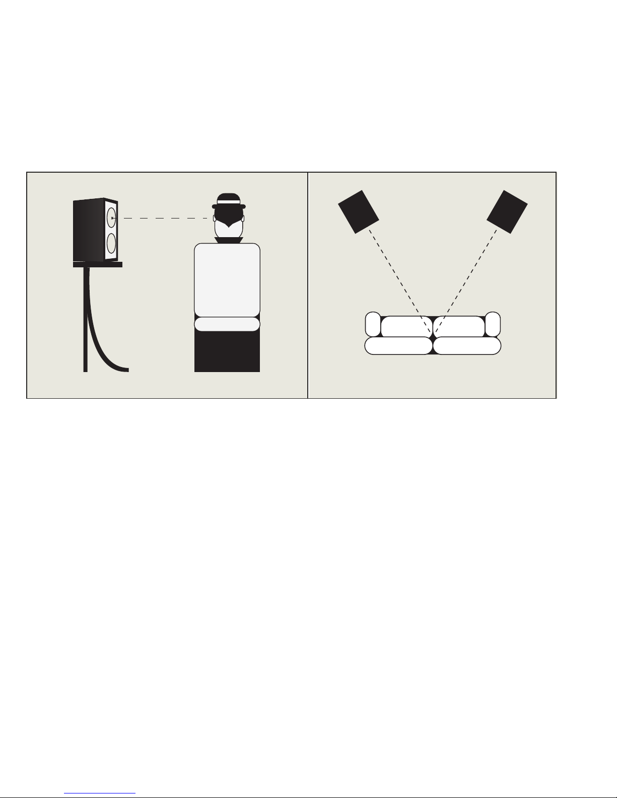
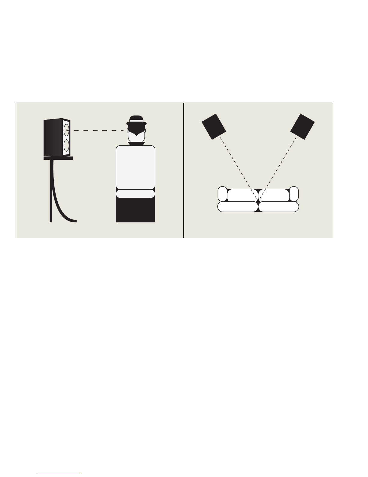
- The speakers should be slightly
toed in.
Page 11
11
EN
- Where possible the speakers
should be at least 50 cm from
the side walls.
- Small Loudspeaker systems
should be placed on shelves (if
this is not possible, put them
on a stand) so that the tweeter
should be more or less at the
same level of the listener's ears.
If, for any reason, some of these
conditions cannot be met, it is
possible to modify the sound by
regulating tile tone controls or
by using an equalizer. It should,
however, be remembered that
in these cases more benefit is
achieved by attenuating the
frequencies rather than by
increasing them.
All the speakers can be use in
multichannel configuration.
Page 12

12
Stray Magnetic
Fields/
The speaker drive units create static stray magnetic fields that extend
beyond the boundaries of the cabinet. We recommend you keep
magnetically sensible devices (CRT television and computer screens,
computer discs, audio and video tapes, swipe cards and the like) at
least 0.5m from the speaker. OLED, LCD and plasma screens are not
affected by magnetic fields.
Page 13

13
EN
Maintance and
Warrenties/
Please take the time to carefully read and follow these important
safety instructions.
Please save this sheet for future reference.
WARNING:
Do not expose this appliance to dripping or splashing, and do not place
objects filled with liquids, such as vases, on or near the appliance. As
with any electronic products, use care not to spill liquids in to any part
of the system. Liquids can cause a failure and/or fire hazard.
Do not place any free flames sources, such as lighted candles, on or
near the appliance.
Do not install near any heat sources such as radiators, heat registers,
stoves, or other appliances (including amplifiers) that produce heat.
Consult the dealer or an experienced radio/TV technician for help.
Clean only with a dry cloth.
This product contains magnets, which can be harmful to pacemaker
wearers.
CAUTION
Make no modifications to the system or accessories.
Unauthorized alterations may compromise safety,
regulatory compliance, and system performance.
Guarantee will be invalidated as well.
Page 14
14
Stand Assembly/
Page 15

15
EN
Stand Assembly/
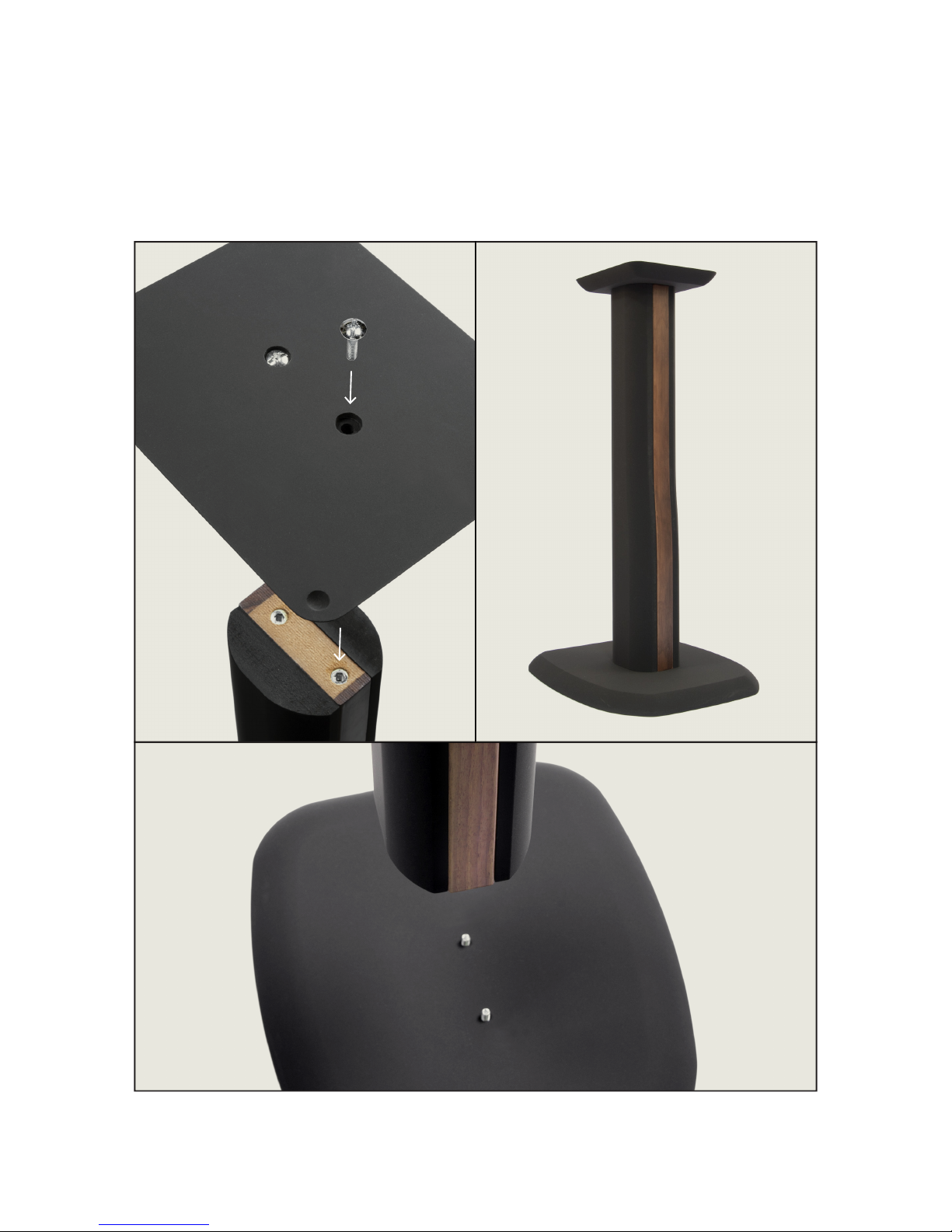
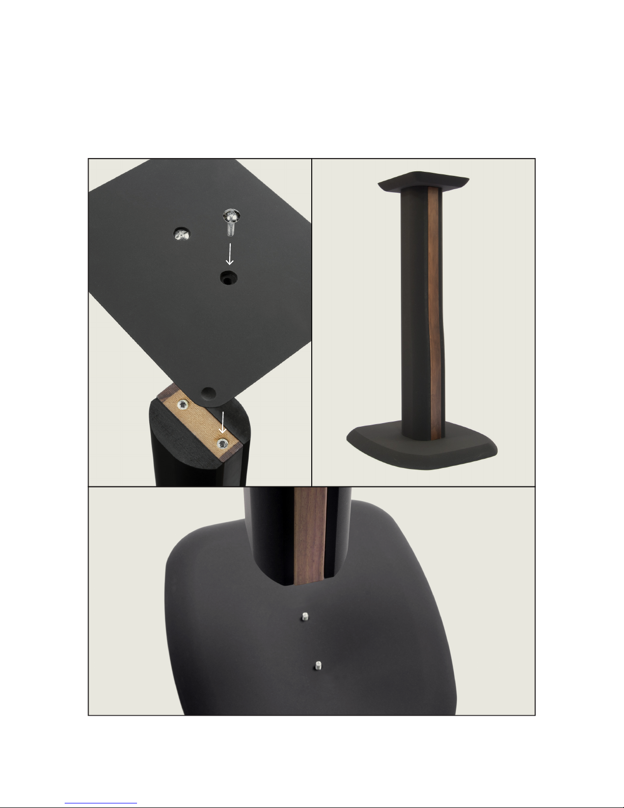
PARTS FOR 2 STANDS:
Screw for fixing the upper and the lower base (4 pcs)
Upper base (2 pcs)
Base Bottom (2 pcs)
Stem (2 pcs)
Rubber (8 pcs)
INSTRUCTIONS:
Place the lower base on the bottom of the stem and align the holes
for the screws. Use two screws to join the two pieces being careful
not to over thighten.
Place the upper base on the top of the stem and align the holes for
the screws. Use two screws to join the two pieces being careful
not to over thighten.
Attach the rubbers provided at the bottom of the lower base.
Place the speaker into the appropriate calls on the base top.
Page 16

2
MANUALE
UTENTE
ITALIANO
Page 17

3
IT
/INDICE/
ASSEMBLAGGIO
pag. 4
CAVI DI COLLEGAMENTO
pag. 5
COLLEGAMENTI ELETTRICI
pag. 6
AMPLIFICATORI
pag. 8
AMBIENTE D'ASCOLTO
pag. 9
POSIZIONAMENTO DEI DIFFUSORI
pag. 10
CAMPI MAGNETICI DISPERSI
pag. 12
PULIZIA, MANUTENZIONE, NORME DI SICUREZZA
pag. 13
ASSEMBLAGGIO STAND
pag. 14
Page 18
4
Assemblaggio/
Valido solo per il modello Ursa Major.
Place the 4 supplied dampers into the slot on the lower part of the
speaker and carefully place the top until full contact of the two parts.
Page 19
5
IT
Le connessioni migliori si ottengono con collegamenti brevi e cavi
di generoso diametro. I cavi devono essere sempre di tipo bipolare-
multi filare (in nessuno caso si deve usare cavo unipolare rigido),
possibilmente di ampia sezione, come i cavi per collegamenti hi-fi
correntemente reperibili presso i rivenditori specializzati.
Per coloro che intendono utilizzare normali conduttori elettrici, è
bene fare riferimento ai seguenti requisiti minimi:
Cavi di
collegamento/
Distanza
amplificatore/diffusore
Fino a 5 metri
Da 5 a 10 metri
Oltre 10 metri
Sezione minima
del conduttore
0,75 mm2
1.00 mm2
2.00 mm2
Page 20
6
Collegamenti
elettrici/
Tutti i collegamenti devono essere effettuati con i componenti
dell’impianto spenti.
I morsetti di uscita degli amplificatori sono contrassegnati dal colore
rosso per il polo positivo e dal colore nero per il polo negativo.
I morsetti di ingresso dei diffusori Chario riportano chiaramente
l’indicazione + (per il polo positivo) e - (per il polo negativo).
Durante il collegamento amplificatore-casse acustiche, rispettate
scrupolosamente la corretta polarità di ingresso.
Page 21
7
IT
Collegamenti
elettrici/
Per il modello Ursa Major utilizzare il cavo in dotazione per collegare
la parte inferiore alla parte superiore.
Per il modello Ursa Major è anche possibile il collegamento a cavo
sdoppiato (bi-wiring) oppure ad amplificatore sdoppiato (bi-amping).
In tal modo la parte bassa potrà essere alimentata separatamente
dagli altri trasduttori.
N.B.
U na eventuale inversione della polarità NON danneggia
i diffusori acustici, viene però compromesso l’ascolto
(con un risultato sonoro che comporta una sensibile perdita
di potenza) e viene alterata l’immagine stereofonica, con una
difficile localizzazione delle sorgenti.
Page 22

8
E’ possibile accoppiare i diffusori ad amplificatori di potenza più
elevata rispetto ai valori suggeriti: in questo caso va sottolineata la
necessita di una certa cautela nell’uso della manopola di volume, per
non danneggiare i diffusori con flussi di potenza eccessivi.
E’ anche consigliabile, utilizzando amplificatori di bassa potenza,
non mantenere al massimo la manopola di volume (soprattutto con
i controlli di tono laterali) per evitare il rischio di danneggiare
seriamente il tweeter.
Generalmente l’amplificazione consigliata è direttamente
proporzionale alla dimensione della stanza di ascolto. E’ vivamente
consigliato di avere un minimo di 1W per ogni m3.
La potenza dell’amplificatore è indicata per un valore di impedenza di
4 Ohm.
Per le connessioni tra amplificatore e sorgente fare riferimento ai
manuali forniti con i dispositivi in possesso o reperibili presso gli
appositi siti internet.
Amplificatori/
Page 23

9
IT
L’ambiente d’ascolto è di fondamentale importanza nel determinare la
qualità dell’ascolto domestico. La sua forma, le suppellettili e i mobili
in esso contenuti, i drappeggi, le tende e i tappeti eventualmente
presenti, le superfici di vetro o acusticamente riverberanti e le
superfici assorbenti determinano le caratteristiche dell’ambiente
d’ascolto.
L’ambiente d’ascolto va dunque ottimizzato, spostando
opportunamente i mobili e calibrando le superfici riflettenti e
assorbenti, in modo da ottenere, se possibile, la massima neutralità
acustica dell’ambiente.
Per una migliore ottimizzazione dell’ambiente d’ascolto rivolgersi a
tecnici specializzati e professionisti in consulenza acustica.
Ambiente
d’ascolto/
Page 24
10
Una volta ottimizzata l’acustica
ambientale, occorre sistemare i
diffusori. Anche in questo caso
(vista la varietà di soluzioni
possibili) è bene procedere
per tentativi, sperimentando
posizioni diverse, ma tenendo
comunque presente che si
consiglia di:
- Evitare che ci siano oggetti
ingombranti interposti tra la
posizione d’ascolto e i diffusori.
- Scegliere una posizione
d’ascolto che sia ad almeno 1
metro dalla parete alle spalle
dell’ascoltatore.
Posizionamento
diffusori/
- Bisogna ottimizzare la distanza
tra i diffusori, si procede per
gradi, partendo da una distanza
minima di 1,5m (ove possibile)
distanziare tra loro i diffusori in
modo progressivo, sino a quando,
ascoltando un programma
stereofonico, si avvertirà un
vuoto nel centro. A quel punto
i diffusori vanno riavvicinati
fino ad avere un fronte sonoro
uniforme.
- Bisogna angolare leggermente
i diffusori (cioè rivolgerli
leggermente verso la zona di
ascolto).
1,5 m
1 m
0,5 m
0,5 m
Page 25
11
IT
- Occorre distanziare i diffusori
dalle pareti laterali (ove
possibile) di almeno 50 cm.
- Per i modelli Bookshelf
occorre scegliere sempre il
posizionamento a scaffale (se
non è possibile il posizionamento
su piedistalli) per consentire
di avere sempre il tweeter
circa all'altezza dell'orecchio
dell'ascoltatore.
Se per motivi contingenti alcune
di queste condizioni non possono
venire rispettate, è possibile
modificare il suono agendo sui
controlli di tono o utilizzando un
equalizzatore. Va però ricordato
che in questi casi si otterrà
un reale beneficio agendo IN
ATTENUAZIONE sulle frequenze,
MAI IN ESALTAZIONE.
Tutti i diffusori possono
essere utilizzati anche per
configurazioni multicanale.
Page 26

12
Campi magnetici
dispersi/
Gli altoparlanti dei diffusori creano dei campi magnetici che
estendono la loro azione oltre i confini fisici dei mobili. Si consiglia
pertanto di mantenere ad almeno 50 cm di distanza ogni oggetto
sensibile ai campi magnetici (televisori a tubo catodico, nastri audio e
video, carte di credito e simili). Schermi al plasma, OLED, LCD o LED,
al contrario, non risentono dei campi magnetici.
Page 27

13
IT
Pulizia, manutenzione
e norme di sicurezza/
Leggere con attenzione e seguire scrupolosamente le informazioni
importanti sulla sicurezza.
Conservare questo documento come riferimento per il futuro.
AVVERTENZE
Non esporre i diffusori a gocce o schizzi e non porre oggetti colmi di
liquidi, quali vasi, sopra o accanto all’apparecchio. Come per qualsiasi
prodotto elettronico, è importante che all’interno delle parti del
sistema non penetrino liquidi in quanto potrebbero causare guasti e/o
rischio di incendio.
Non collocare sorgenti di fiamme libere (ad esempio candele accese)
sui diffusori o nelle vicinanze degli stessi.
Non installare i diffusori in prossimità di fonti di calore, quali
termosifoni, radiatori, stufe o altri apparati (compresi gli amplificatori
che generano calore).
Affidarsi a personale qualificato per tutti gli interventi di assistenza.
Utilizzare solo un panno asciutto per la pulizia.
Il prodotto contiene magneti che potrebbero risultare pericolosi per i
portatori di pacemaker.
ATTENZIONE
Non apportare modifiche al sistema o agli accessori, in
quanto le modifiche non autorizzate possono compromettere
la sicurezza, la conformità alle norme e le prestazioni del
sistema. Nonché la manomissione dell’apparecchiatura fa
decadere la garanzia.
Page 28
14
Assemblaggio
stand/
Page 29

15
IT
Assemblaggio
stand/
COMPONENTI PER DUE STAND:
Viti per fissaggio base superiore e inferiore (4 pz)
Base supriore (2 pz)
Base inferiore (2 pz)
Stelo (2 pz)
Gommini (8 pz)
ISTRUZIONI:
Posizionare la base inferiore sulla parete inferiore dello stelo e
allineare i buchi per le viti. Utilizzare due viti per unire
i due pezzi facendo attenzione a non serrare eccessivamente le viti.
Poisizionare la base superiore sulla parte supriore dello stelo e
allineare i buchi per le viti. Utilizzare due viti per unire
i due pezzi facendo attenzione a non serrare eccessivamente le viti.
Attaccare i gommini in dotazione nella parte inferiore della
base inferiore.
Posizionare il diffusore negli appositi inviti posti sulla base superiore.
Page 30

16
www.charioloudspeaker.com
 Loading...