

Page 1
CT4000 Family
ChargePoint® Networked Charging Station
ChargePoint, Inc.
1692 Dell Ave.
Campbell, CA 95008-6901 USA
US toll free: +1-877-370-3802
www.chargepoint.com
Installation
Guide
Document P/N: 75-001084-01 Rev. 4
Page 2

SAVE THESE IMPORTANT SAFETY INSTRUCTIONS
This manual contains important instructions that must be followed during installation of a ChargePoint® Networked Charging Station.
Grounding instructions
The ChargePoint® Charging Station must be connected to a grounded, metal, permanent wiring system; or an equipment-grounding
conductor is to be run with circuit conductors and connected to the equipment grounding terminal or lead on the Electric Vehicle Supply
Equipment (EVSE). Connections to the EVSE shall comply with all applicable codes and ordinances.
FCC Compliance Statement
This equipment has been tested and found to comply with the limits for a Class A digital device pursuant to Part 15 of the FCC Rules.
These limits are designed to provide reasonable protection against harmful interference when the equipment is operated in a commercial
environment. This equipment generates, uses, and can radiate radio frequency energy and, if not installed and used in accordance with the
manufacturer’s instruction manual, may cause harmful interference with radio communications. Operation of this equipment in a residential
area is likely to cause harmful interference, in which case, you will be required to correct the interference at your own expense.
Important: Changes or modifications to this product not authorized by ChargePoint, Inc., could affect the EMC compliance and revoke your
authority to operate this product.
Exposure to Radio Frequency Energy: The radiated power output of the 802.11 b/g/n radio and cellular modem (optional) in this device is
below the FCC radio frequency exposure limits for uncontrolled equipment. This device should be operated with a minimum distance of at
least 20 cm between the 802.11 b/g/n and cellular antennas and a person’s body and must not be co-located or operated with any other
antenna or transmitter by the manufacturer, subject to the conditions of the FCC Grant.
Industry Canada
This device complies with Industry Canada license-exempt RSS standard(s). Operation is subject to the following two conditions: (1) this
device may not cause interference, and (2) this device must accept any interference, including interference that may cause undesired
operation of the device.
Le présent appareil est conforme aux CNR d’Industrie Canada applicables aux appareils radio exempts de licence. L’exploitation est autorisée
aux deux conditions suivantes : (1) l’appareil ne doit pas produire de brouillage, et (2) l’utilisateur de l’appareil doit accepter tout brouillage
radioélectrique subi, même si le brouillage est susceptible d’en compromettre le fonctionnement.
FCC/IC Compliance Labels
Go to http://www.chargepoint.com/labels/.
Safety and compliance
This document provides instructions to install the ChargePoint® Charging Station and should not be used for any other product. Before
installing the ChargePoint® Charging Station, you should review this manual carefully and consult with a licensed contractor, licensed
electrician and trained installation expert to ensure compliance with local building practices, climate conditions, safety standards, and all
applicable codes and ordinances.
The ChargePoint® Charging Station should be installed only by a licensed contractor and a licensed electrician and in accordance with all
local and national codes and standards. The ChargePoint® Charging Station should be inspected by a qualified installer prior to the initial
use. Under no circumstances will compliance with the information in this manual relieve the user of his/her responsibility to comply with all
applicable codes or safety standards. This document describes the most commonly-used installation and mounting scenarios. If situations
arise in which it is not possible to perform an installation following the procedures provided in this document, contact ChargePoint, Inc.
ChargePoint, Inc. is not responsible for any damages that may occur resulting from custom installations that are not described in this
document.
No accuracy guarantee
Reasonable effort was made to ensure that the specifications and other information in this manual are accurate and complete at the time of
its publication. However, the specifications and other information in this manual are subject to change at any time without prior notice.
Warranty information and disclaimer
Your use of, or modification to, the ChargePoint® Charging Station in a manner in which the ChargePoint® Charging Station is not intended to
be used or modified will void the limited warranty. Other than any such limited warranty, the ChargePoint products are provided “AS IS,” and
ChargePoint, Inc. and its distributors expressly disclaim all implied warranties, including any warranty of design, merchantability, fitness for a
particular purposes and non-infringement, to the maximum extent permitted by law.
Limitation of liability
IN NO EVENT SHALL CHARGEPOINT, INC. OR ITS AUTHORIZED DISTRIBUTORS BE LIABLE FOR ANY INDIRECT, INCIDENTAL, SPECIAL,
PUNITIVE, OR CONSEQUENTIAL DAMAGES, INCLUDING WITHOUT LIMITATION, LOST PROFITS, LOST DATA, LOSS OF USE, COST OF COVER,
OR LOSS OR DAMAGE TO THE CHARGEPOINT® CHARGING STATION, ARISING OUT OF OR RELATING TO THE USE OR INABILITY TO USE
THIS MANUAL, EVEN IF CHARGEPOINT, INC. OR ITS AUTHORIZED DISTRIBUTORS HAVE BEEN ADVISED OF THE POSSIBILITY OF SUCH
DAMAGES.
Copyright and trademarks
©2013 ChargePoint, Inc. All rights reserved. This material is protected by the copyright laws of the United States and other countries. It
may not be modified, reproduced or distributed without the prior, express written consent of ChargePoint, Inc. CHARGEPOINT is a U.S.
and European Union registered trademark and service mark of ChargePoint, Inc. and can not be used without the prior written consent of
ChargePoint. All other products or services mentioned are the trademarks, service marks, registered trademarks or registered service marks
of their respective holders. ChargePoint, Inc. has several patents filed.
Page 3

Contents
1 Introduction
Summary of Shipping Boxes ...........................................1-1
Installation Sequence ................................................ 1-2
Before Installing ..................................................... 1-2
Specifications ...................................................... 1-3
Dual Circuit Wiring Diagram ..........................................1-4
Shared Power Wiring Diagram ........................................1-5
Grounding Requirements .............................................1-6
2 Installing a Bollard Mount
Before You Start .................................................... 2-1
Overview of Steps ................................................... 2-1
Step 1: Check Boxes for Correct Contents ...............................2-2
Step 2: Prepare Pole/Base Plate for Mounting ...........................2-3
Step 3: Mount Pole/Base Plate ........................................2-4
Step 4: Install Main Body .............................................2-5
Step 5: Prepare Retractor for Mounting ................................2-6
Step 6: Install Retractor ..............................................2-7
Step 7: Connect Wiring ..............................................2-8
Step 8: Check Voltages ..............................................2-9
3 Installing a Wall Mount
Before You Start .................................................... 3-1
Overview of Steps ................................................... 3-1
Step 1: Check Boxes for Correct Contents ...............................3-2
Step 2: Drill Holes in Wall .............................................3-3
Step 3: Mount Rear Brackets to Wall ...................................3-4
Step 4: Prepare Retractor for Mounting ................................3-5
Step 5: Mount Retractor ..............................................3-6
Step 6: Install Conduit ...............................................3-7
Step 7: Install Main Mody .............................................3-8
Step 8: Connect Wiring ..............................................3-9
Step 9: Check Voltages .............................................3-10
i
Page 4

4 Installing the Head and Top Cap
Before You Start .................................................... 4-1
Overview of Steps ................................................... 4-1
Step 1: Check Boxes for Correct Contents ...............................4-2
Step 2: Prepare Head Assembly for Mounting ...........................4-4
Step 3: Slide Head Assembly Into Body ................................4-6
Step 4: Connect Head Assembly ......................................4-7
Step 5: Verify the Station Operates Correctly ...........................4-8
Step 6: Install Cable Clamps .........................................4-10
Step 7: Secure Head Assembly ........................................4-11
5 Preparing the Station for Activation on ChargePoint
Before You Start .................................................... 5-1
Overview of Steps ................................................... 5-1
Step 1: Pinpoint the Station ...........................................5-2
Step 2: Document the Radio Groups ...................................5-5
Step 3: Complete the Post-Installation Checklist .........................5-6
6 Troubleshooting
Check the Station’s Display ........................................... 6-1
Display Station Codes ................................................6-1
Description of Station Codes .........................................6-2
Charging Cable Doesn’t Move Freely ...................................6-5
Appendix A: Preparing the Installation Site for a Bollard Mount
Appendix B: Removing or Replacing the EV Charging Sign
Appendix C: CT4000 Power Sharing Instructions
Appendix D: Limited Product Warranty
ii
Page 5
Introduction
This document provides step-by-step instructions on how to install a CT4000 ChargePoint® Charging Station.
Summary of Shipping Boxes
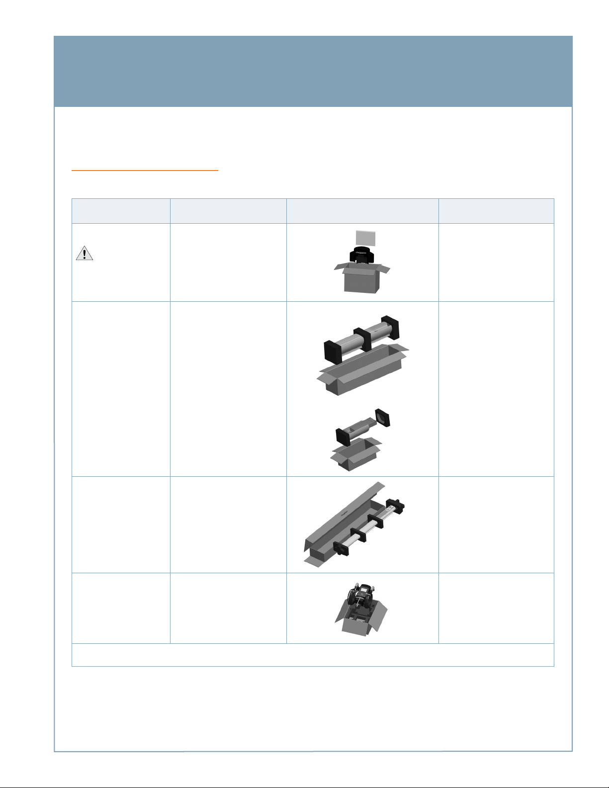
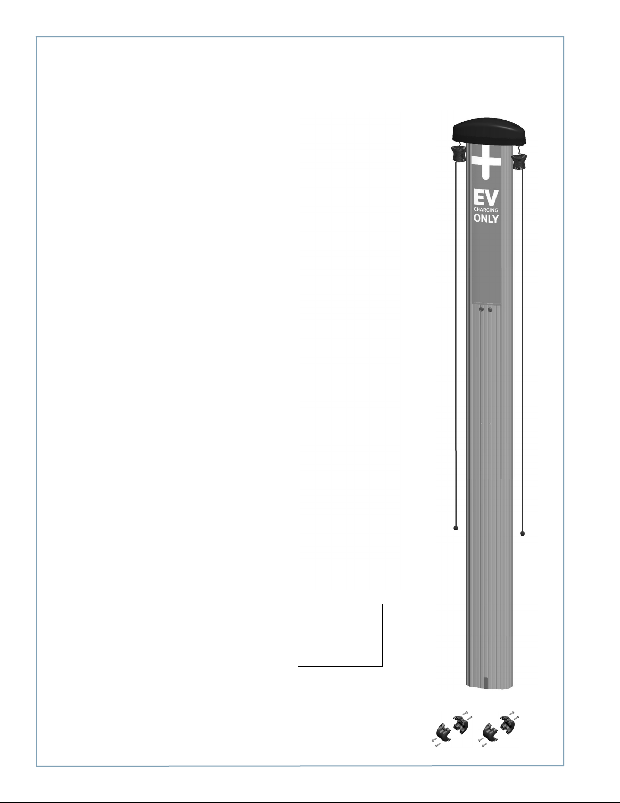
Each CT4000 charging station ships in four boxes:
1
Assembly name... Label on box says.... High level overview of box contents...
Top Cap
IMPORTANT: Open
this box first—it contains the
printed Installation Guide
Body CT40X1-BD or CT40X3-BD
Cord Management Retractor CT4000-CMK
CT40XX-CAP*
Bollard Mount (CT40X1-BD):
Includes a power sharing kit
(CT4020-PSHARE) that allows both
ports on a dual port station to share
a single 40A circuit.
Wall Mount (CT40X3-BD):
For Installation Instructions,
see...
Chapter 4
Chapter 2 - Bollard
Chapter 3 - Wall Mount
Chapter 2 - Bollard
Chapter 3 - Wall mount
Head CT40X0-HD* or CT40X0-HD-GW*
For gateway stations the box also
includes a Network Enablement
Kit, CT4000-NEK1 (US) or
CT4000-NEK2 (Canada)
*The last two digits of the four-digit model number depends on the station’s features. The third digit (CT40X0) is “1” if the station has a single charging port, or ‘2”
if the station has two charging ports. The last digit (CT401X) is either a 1 (bollard mount) or 3 (wall mount).
NOTE: A more detailed list of the contents in each shipping box is provided in the associated chapter with the step-by-step
installation instructions.
Chapter 4
1-1
Page 6
ChargePoint® Charging Stations
Installation Sequence
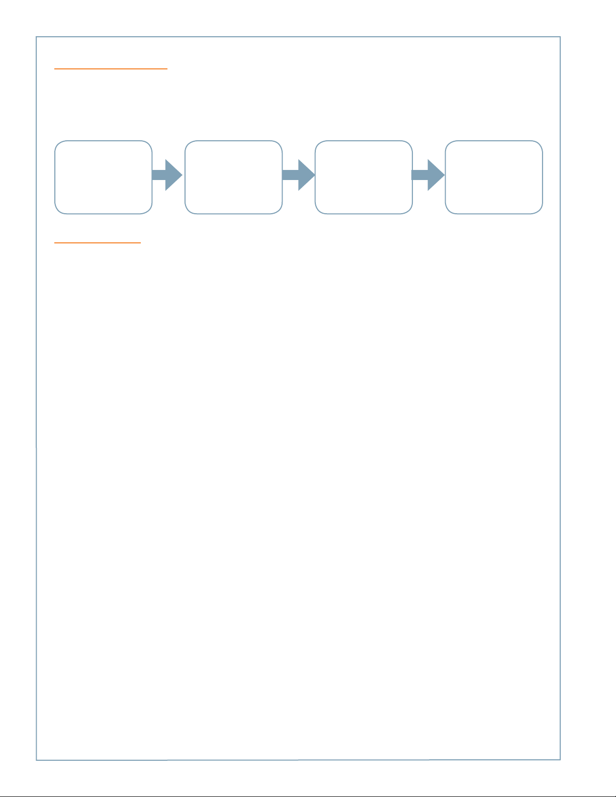
Regardless of the specific type of CT4000 charging station you are installing, and the options included, the high level
installation sequence is the same:
PREPARE THE INSTALL THE INSTALL THE HEAD PREPARE THE STATION
INSTALLATION SITE MOUNTING OPTION AND TOP CAP FOR ACTIVATION
Ensure the wiring, circuit
protection, and metering
is in place. Read the
remainder of Chapter 1. If
installing a bollard mount,
also read Appendix A.
Depending on the type of
station, follow the steps in
either:
Chapter 2 - Bollard
Chapter 3 - Wall mount
Follow the steps in
Chapter 4
Follow the steps in
Chapter 5
Before Installing
• Ensure that the appropriate wiring, circuit protection, and metering is in place at the installation location by reviewing
the specifications, wiring diagrams, and grounding requirements in the remainder of this chapter.
• Ensure that adequate CDMA (Verizon) or GSM (AT&T, Rogers) cellular coverage is available at the installation location. To
ensure adequate signal strength in underground garages or other enclosed parking structures, cellular repeaters may be
required.
• For bollard mount charging stations, prepare the installation site by following the instructions in Appendix A. The
mounting template for the bollard is stapled into the center fold of this document and a PDF version is available at
www.chargepoint.com/support-installation-guides.php. Ensure the PDF version is accurate by printing it at 100% scale on
11” x 17” paper and then verifying at least one dimension.
• Review the CT4000 Data Sheet (available at www.chargepoint.com/support-product-data-sheets.php).
• Review the contents of this document to familiarize yourself with the contents of each shipping box and the required
installation steps.
1-2
Page 7
Specifications
Introduction
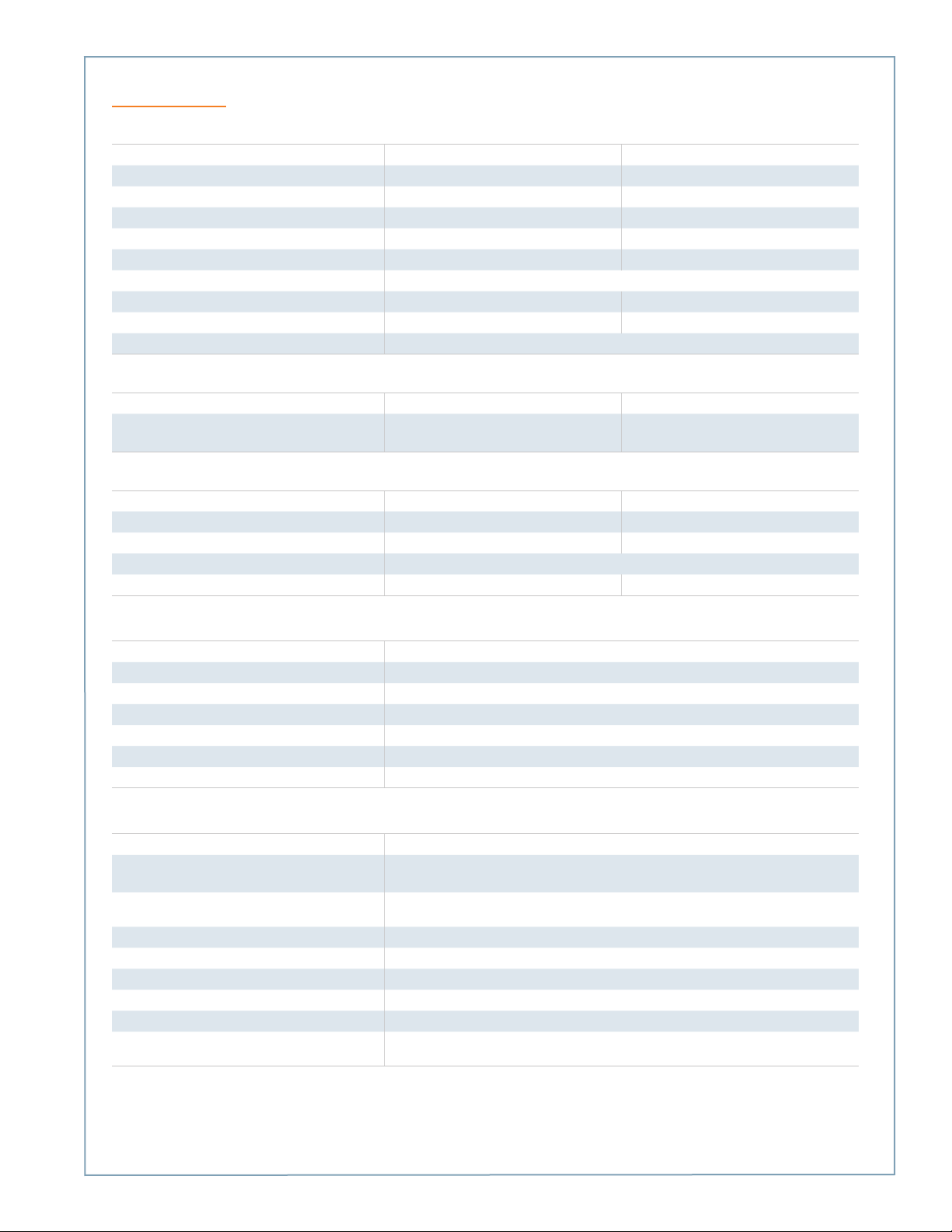
Electrical Input
AC Power Input Rating - Standard 208/240VAC 60Hz single phase @ 32A 208/240VAC 60Hz single phase @ 32A x 2
AC Power Input Rating - Power Sharing n/a 208/240 VAC 60Hz single phase @ 32A
Input Power Connections - Standard One 40A branch circuit. Two independent 40A branch circuits.
Input Power Connections - Power Sharing n/a One 40A branch circuit
Required Service Panel Breaker - Standard 40A dual pole (non-GFCI type) 40A dual pole (non-GFCI type) x 2
Required Service Panel Breaker - Power Sharing n/a 40A dual pole (non-GFCI type)
Service Panel GFCI Do not provide external GFCI as it may conflict with internal GFCI (CCID)
Wiring - Standard 3-wire (L1, L2, Earth) 5-wire (L1, L1, L2, L2, Earth)
Wiring - Power Sharing n/a 3-wire (L1, L2, Earth)
Standby Power 15W typical (standby), 20W maximum (operation)
Single Port Dual Port
Electrical Output
AC - Standard 7.2kW (240VAC @ 30A) 7.2kW (240VAC @ 30A) x 2
AC - Power Sharing n/a 7.2kW (240VAC @ 30A) x 1 OR
3.8kW (240VAC @ 16A) x 2
Functional Interfaces
Plug(s) Type SAE J1772™ SAE J1772™ x 2
Charging Cable Length 18’ (5.5 meters) 18’ (5.5 meters) x 2
Overhead Cable Management System Yes Yes
Card Reader ISO 15693, 14443, NFC
Locking Holster Yes Yes x 2
Safety and Connectivity Features
Ground Fault Detection 20mA CCID with auto retry
Open Safety Ground Detection Continuously monitors presence of safety (green wire) ground connection
Plug-Out Detection Power terminated per SAE J1772™ specifications
Power Measurement Accuracy +/- 2% from 2% to full scale (32A)
Power Report/Store Interval 15 minute, aligned to hour
Local Area Network 2.4 GHz Wi-Fi (802.11 b/g/n)
Wide Area Network 3G GSM, 3G CDMA
Safety and Operational Ratings
Enclosure Rating Type 3R per UL 50E
Safety Compliance UL listed for USA and cUL certified for Canada; Complies with UL 2594, UL 2231-1,
UL 2231-2, and NEC Article 625
Surge Protection 6kV @ 3000A. In geographic areas subject to frequent thunder storms, supplemental
surge protection at the service panel is recommended.
EMC Compliance FCC Part 15 Class A
Operating Temperature -22°F to 122°F (-30°C to +50°C)
Operating Humidity up to 85% @ +50°C (122°F) non-condensing
Non-operating Humidity up to 95% @ +50°C (122°F) non-condensing
Terminal Block Temperature Rating 221°F (105°C)
Maximum Charging Stations per 802.11 Radio
Group
ChargePoint, Inc. reserves the right to alter product offerings and specifications at any time without notice, and is not responsible for typographical or graphical
errors that may appear in this document.
10. Each station must be located within 150 feet “line of sight” of a gateway station.
1 -3
Page 8
ChargePoint® Charging Stations
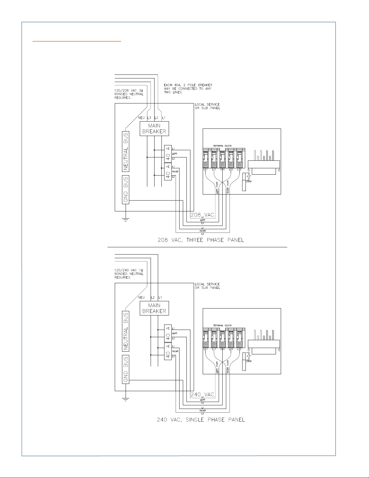
Dual Circuit Wiring Diagram
The following illustration describes the wiring for installing a CT4000 on a dual circuit. Wiring for a single circuit installation is
described on the next page. Grounding requirements are described on page 1-6.
NOTE: Requires two dedicated circuits, each with its own two pole 40 A breaker.
1-4
Page 9
Introduction
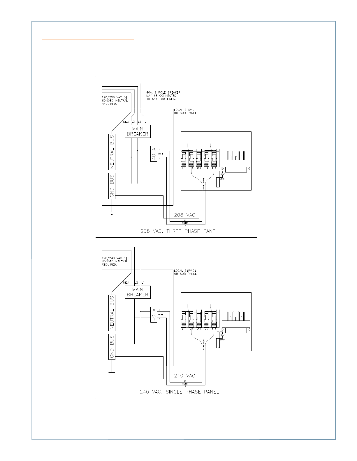
Shared Power Wiring Diagram
The following illustration describes the wiring for installing a dual port CT4000 on a shared single circuit. For this installation,
you will need the power sharing kit to allow both ports to share a two pole 40A circuit breaker. Wiring connections are
provided in Appendix C. Grounding requirements are described on page 1-6.
Wiring for a dual circuit installation, see the previous page.
TERMINAL BLOCK WITH
POWER SHARING JUMPERS INSTALLED
TERMINAL BLOCK WITH
POWER SHARING JUMPERS INSTALLED
1 -5
Page 10
ChargePoint® Charging Stations
Grounding Requirements
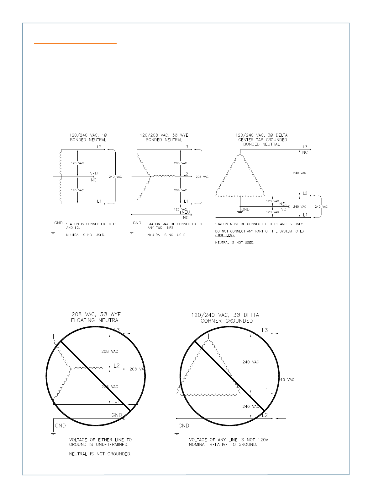
The voltage of either line, relative to ground, must not fall below 80 volts or a Floating Line Connection error occurs (see
page 6-3). Because the voltage of either line relative to ground must not be allowed to fluctuate, use only centergrounded systems. Neutral is not used to power the station but must be properly connected to ground, at the panel or
transformer, to provide the necessary voltage reference relative to ground.
Connect to these systems
In a wye system, connect the station to ANY two lines, as shown below.
In a delta system, connect the station to a center-tapped secondary only, where the center tap is bonded and the station is
connected to L1 and L3. This allows voltages to remain constant regardless of other loads that may be using the lines.
Do not connect to these systems
Do not connect ChargePoint stations to the following types of power sources:
• 120/208 VAC 3 phase wye, ungrounded
• 120/240 VAC 3 phase delta, corner-grounded
• Any system where the center point of the AC power source is not grounded
1-6
Page 11

Installing a Bollard Mount
2
Before You Start
Before installing a bollard mount, prepare the installation site as described in Appendix A. After preparing the installation site,
you need the following:
• Ratchet and 3/8” socket
• 1/2” drive torque wrench and 15/16” 6-point deep socket (for 5/8-11 nut)
• Crescent wrench
• Bubble level
• #2 Phillips screwdriver
• Wire stripper
• Multimeter
Overview of Steps
Installing the bollard mount involves a few simple steps, summarized below and detailed in the remainder of this chapter:
1. Check Boxes for Correct Contents (page 2-2)
2. Prepare Pole/Base Plate for Mounting (page 2-3)
3. Mount Pole/Base Plate (page 2-4)
4. Install Main Body (page 2-5)
5. Prepare Retractor for Mounting (page 2-6)
6. Install Retractor (page 2-7)
7. Connect Wiring (page 2-8)
8. Check Voltages (page 2-9)
When you have completed these steps, you will be ready to install the head and top assemblies as described in Chapter 4.
2-1
Page 12
ChargePoint® Charging Stations
Step 1: Check Boxes for Correct Contents
The bollard mount ships in two boxes as described below.
Main Body
• Main body, pre-assembled with mounting pole/base
plate, rubber bumper, and brackets (1)
• Adapter plastic cap (1)
• ¼”-20 x 1 ¼” screws (4)
• Power sharing kit (use only if installing a dual-port
station on a single 40A circuit) (1)
Cable Management Kit
• Retractor assembly with pre-installed “EV CHARGING
ONLY” sign (1)
• Cable clamps (4)
• Phillips screws (10*)
*Two extra screws are included.
Main Body
Cable Management Kit
2-2
Page 13
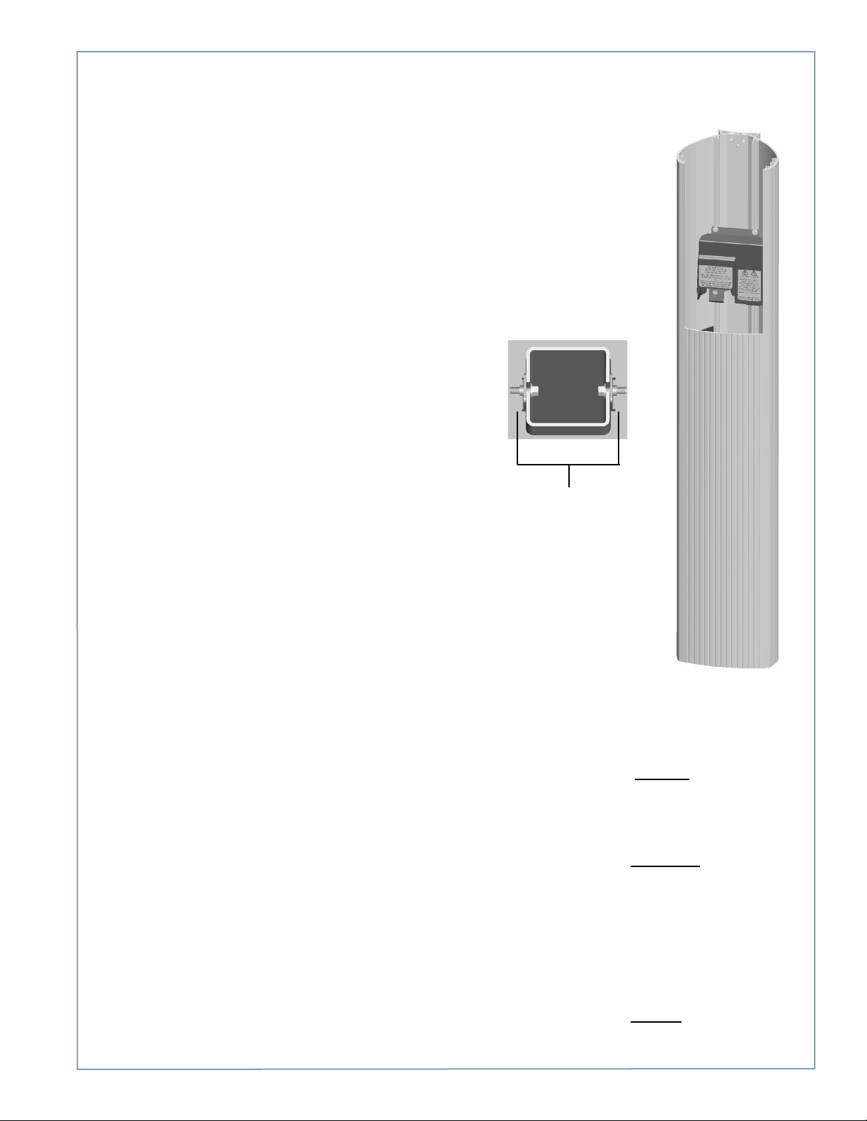
Step 2: Prepare Pole/Base Plate for Mounting
• Use a 3/8” socket wrench to loosen (but not remove)
the two screws holding the pole inside the bollard.
• Remove the pole/base plate assembly from the main
body by pulling it out from the bottom.
• Remove and discard the cardboard shipping spacer.
Installing a Bollard Mount
Loosen the 2 screws
(don’t remove)
Rubber
bumper
Pole
Base
plate
2-3
Page 14
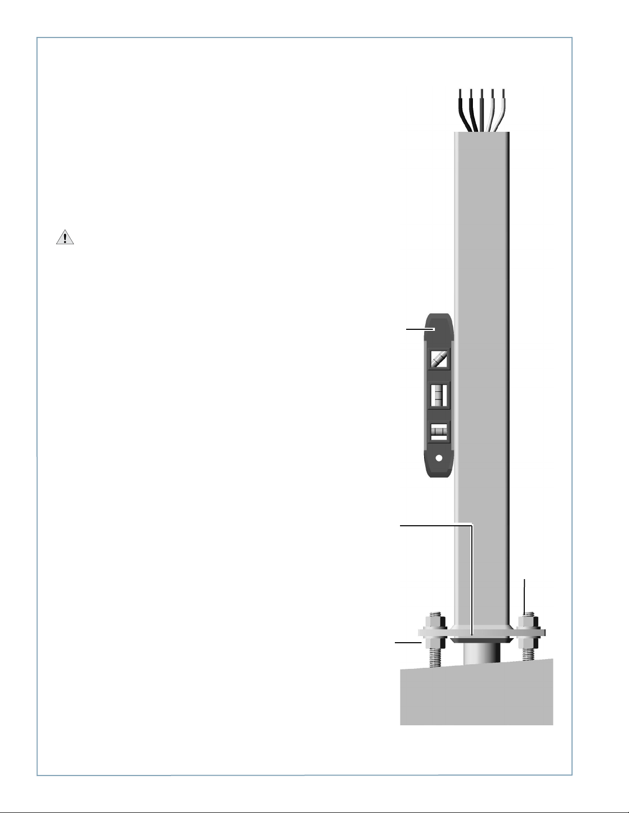
ChargePoint® Charging Stations
tighten the
Step 3: Mount Pole/Base Plate
Prepare the installation site as described in Appendix A,
then mount the pole/base plate assembly as follows:
• Pull wires through conduit.
• Place the pole/base plate assembly over the conduit,
ensuring the long curved edge of the base plate is
located where you want the front of the charging
station located.
• Adjust the lower nuts as necessary to ensure the
mounting pole is level.
• When level, tighten the nuts on top of the base plate
to at least 115-120 ft-lbs.
IMPORTANT: Ensure the pole/base plate is level
by adjusting the nuts underneath the base plate. Verify
accuracy after each adjustment by positioning the level at
various locations on the pole, above each bolt.
Position a level at various
locations, both horizontally
and vertically, including over
each bolt
2-4
Align the longer curved
edge to where you want
to position the front of the
station
Adjust the lower nuts as
necessary to ensure the
pole/base plate is level
When
level,
upper nuts
Page 15
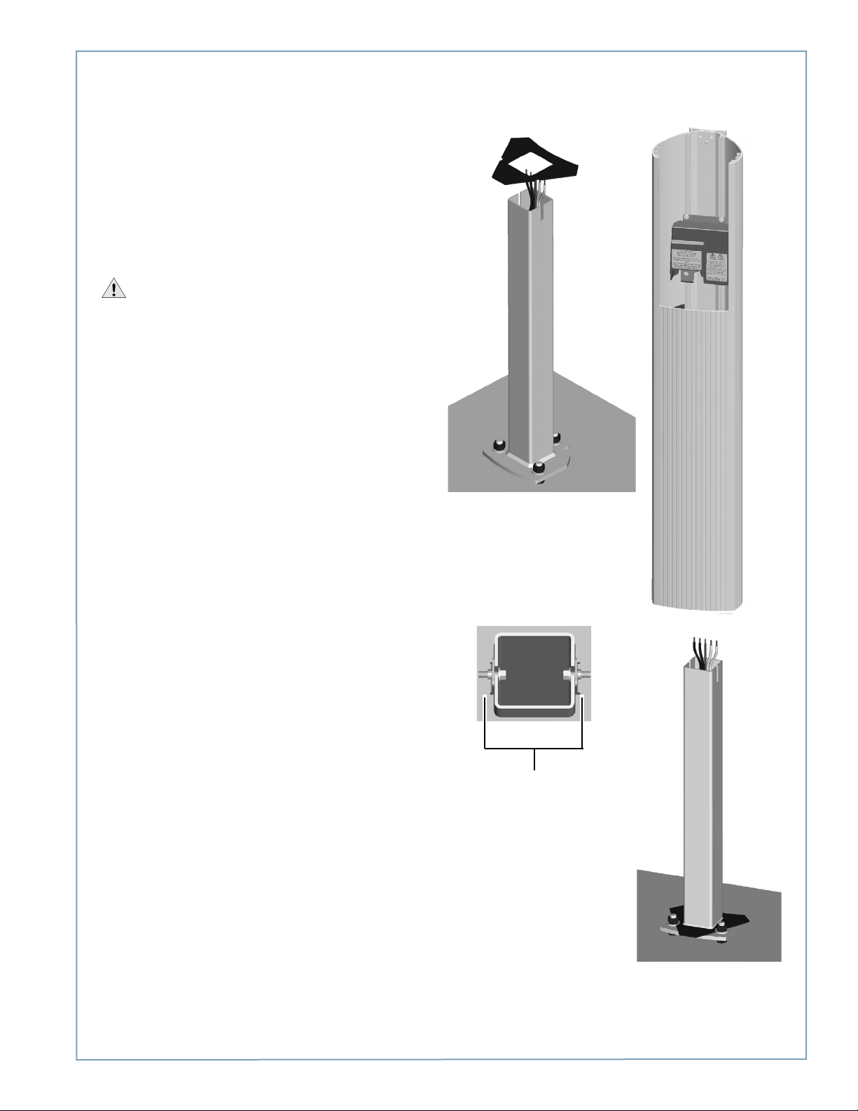
Step 4: Install Main Body
To install the main body:
• Align the notches on the rubber bumper with the
front mounting nuts, then slide it all the way down
the pole until it is flush with the base plate. This
prevents any rocking motion between the main body
and the base plate.
• Slide the body over the mounting pole.
• Re-tighten the screws you loosened in Step 2 to
approximately 80 in-lbs using a 3/8” socket wrench.
IMPORTANT: Ensure the body is firmly aligned to
the bottom surface and that no movement (rocking) can
take place, even when significant pressure is applied.
Installing a Bollard Mount
Position
notches
(2) at
front
Re-tighten the 2 screws
2-5
Page 16
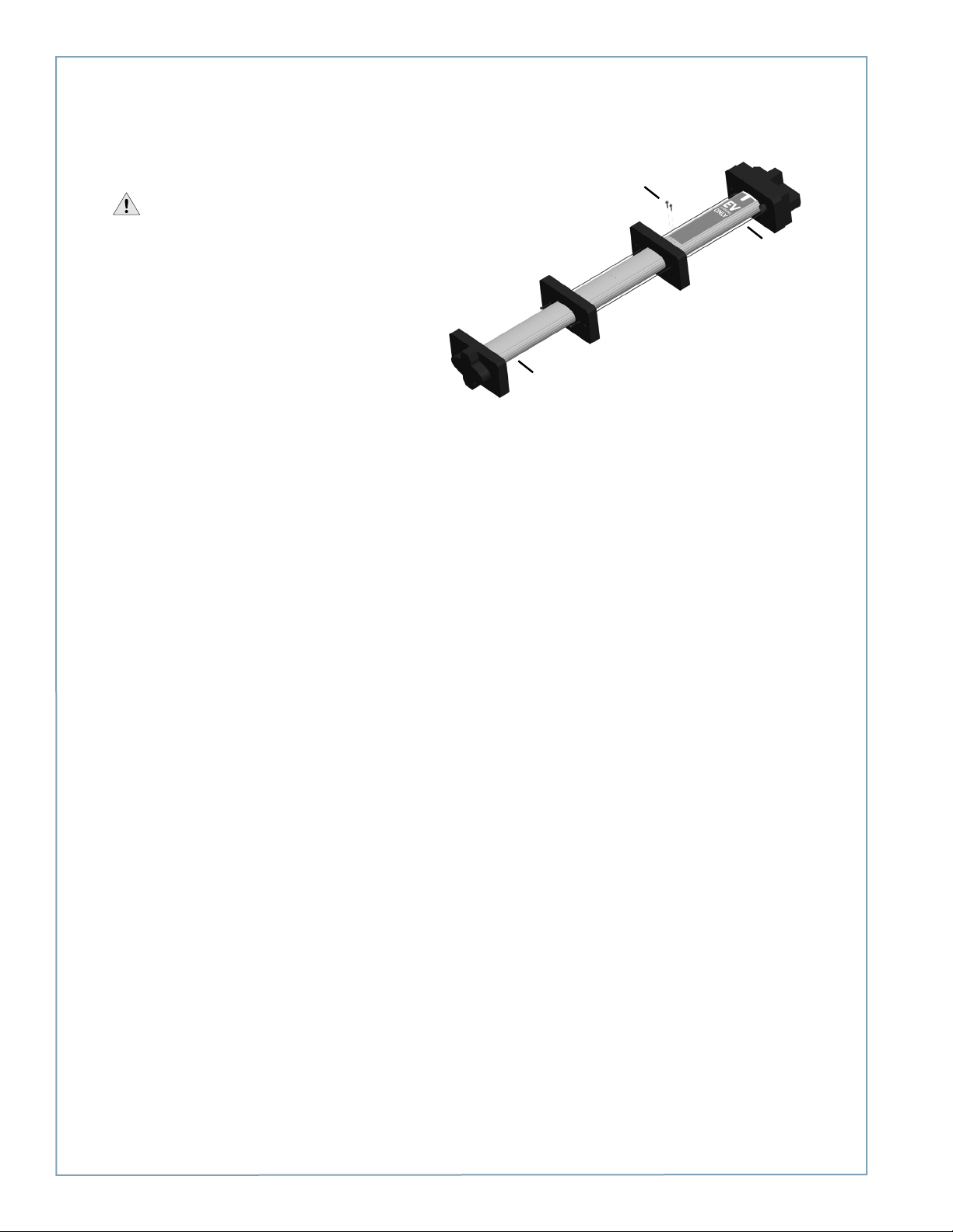
ChargePoint® Charging Stations
Step 5: Prepare Retractor for Mounting
To prepare the retractor for mounting:
• Position the retractor packaging so that the bottom
of the retractor is near the base of the bollard.
IMPORTANT: Do not unwrap the cords.
• Remove and discard the two shipping screws from
the front face of the retractor.
NOTE: When you remove the shipping screws, the
retractor’s counterweights are free to move in either
direction. Therefore, do not tilt or carry the retractor
assembly with the top end lower than the bottom
end.
• Remove the foam packaging from the retractor.
• OPTIONAL: If necessary, remove or replace the EV
PARKING sign. See Appendix B.
Bottom
Discard
shipping
screws
Top
When handling, always
keep the top end higher
than the bottom end.
2-6
Page 17
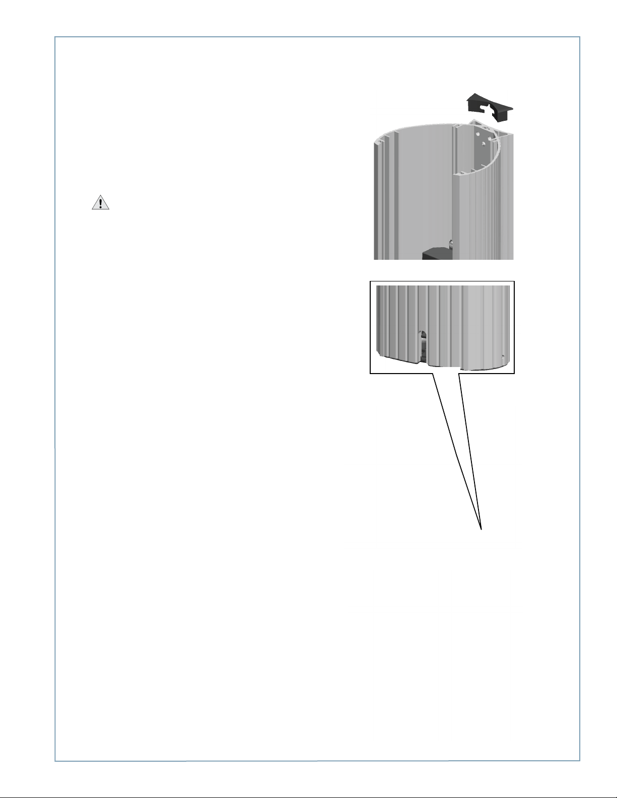
Step 6: Install Retractor
To install the retractor:
• Insert the black cap into the space at the top of the
main body, between the main body and the retractor,
as shown.
• With a Phillips screwdriver and at least one of the
four ¼” - 20 x 1 ¼” screws in hand, position the
retractor against the back of the main body. Place
the slot at the bottom of the retractor over the knob
at the bottom of the main body, as shown.
IMPORTANT: Hold the retractor in place until
you’ve secured it with at least one screw.
• From inside the main body, insert the four ¼” - 20 x
1 ¼” screws through the main body and the retractor,
and tighten to 60 in-lbs.
Installing a Bollard Mount
2-7
Page 18
ChargePoint® Charging Stations
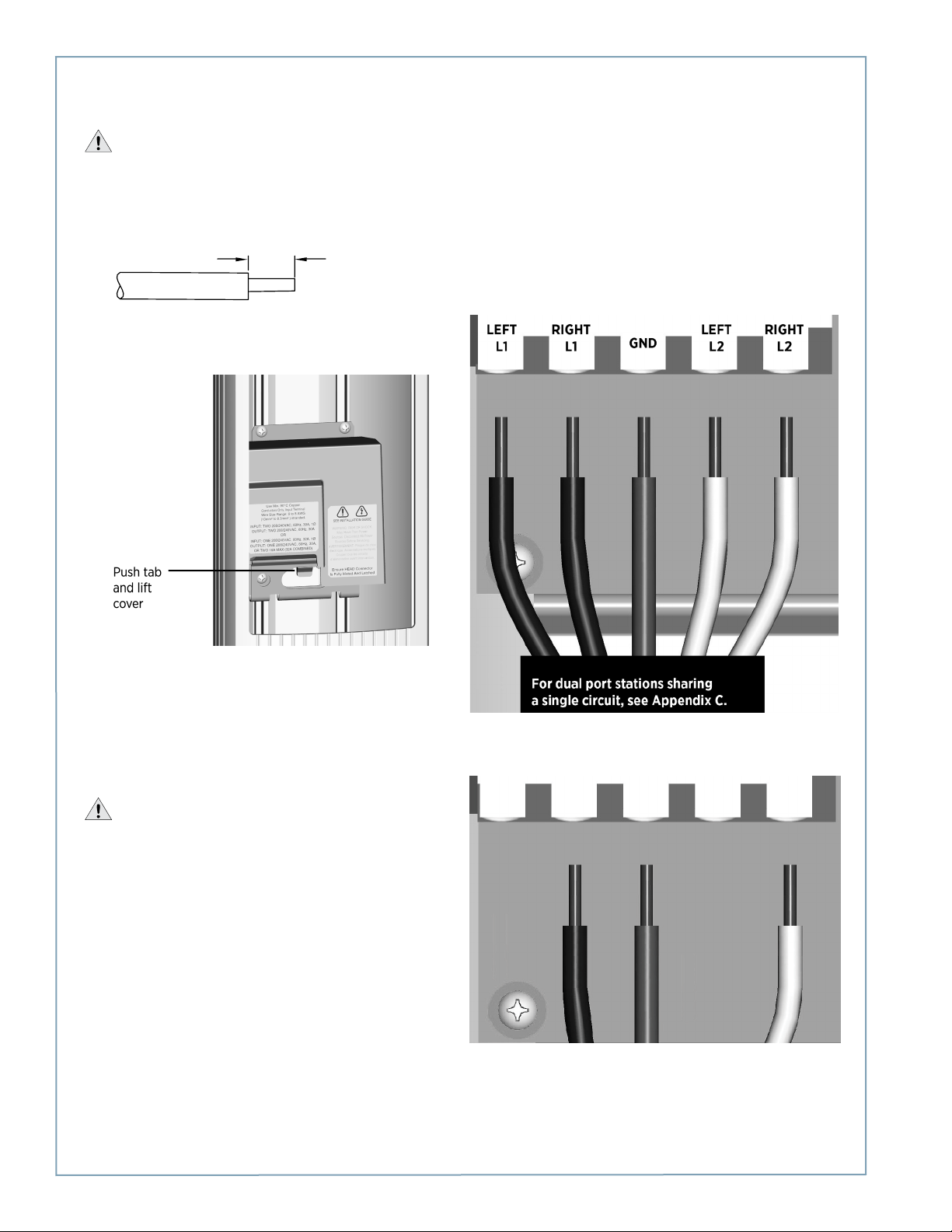
Step 7: Connect Wiring
1/2” (13 mm)
IMPORTANT: To power a dual-port station using a single 40A circuit, use the Power Sharing Kit (CT4020-PSHARE)
provided in the shipping box with the main body. Instead of following the instructions below, see Appendix C. You must also
manually configure the station for power sharing, as described in Appendix C.
If you are not installing a power sharing kit, connect the wiring as follows:
• Strip wires ½” (13 mm).
• Push the black tab on the terminal block to release the
terminal block cover, then slide the cover up until it locks
into the raised position:
• Lift the corresponding white lever on the terminal block,
insert the ground wire into the center connector, then
push the lever down until it clicks into its fully closed
position.
• Lift the corresponding white levers, insert the 240 VAC L1
and L2 wires, then push the levers down until they click
into their fully closed position.
WARNINGS:
• Use copper conductors only.
• Do NOT provide GFCI protection at panel. The CT4000
has built-in GFCI protection.
• In areas with frequent thunder storms, add surge
protection at the service panel for all circuits.
• Use new circuit breakers only. Used breakers can
damage equipment and introduce the potential for an
electrical fire.
• Ensure all power and ground connections, especially
those at the breaker and buss bar, are clean and tight.
Remove all oxide from all conductors and terminals
before connecting wiring.
For dual port stations:
For single port stations, use the connectors indicated for “RIGHT” side only.
LEFT
L1
RIGHT
L1
GND
LEFT
L2
RIGHT
L2
2-8
Page 19
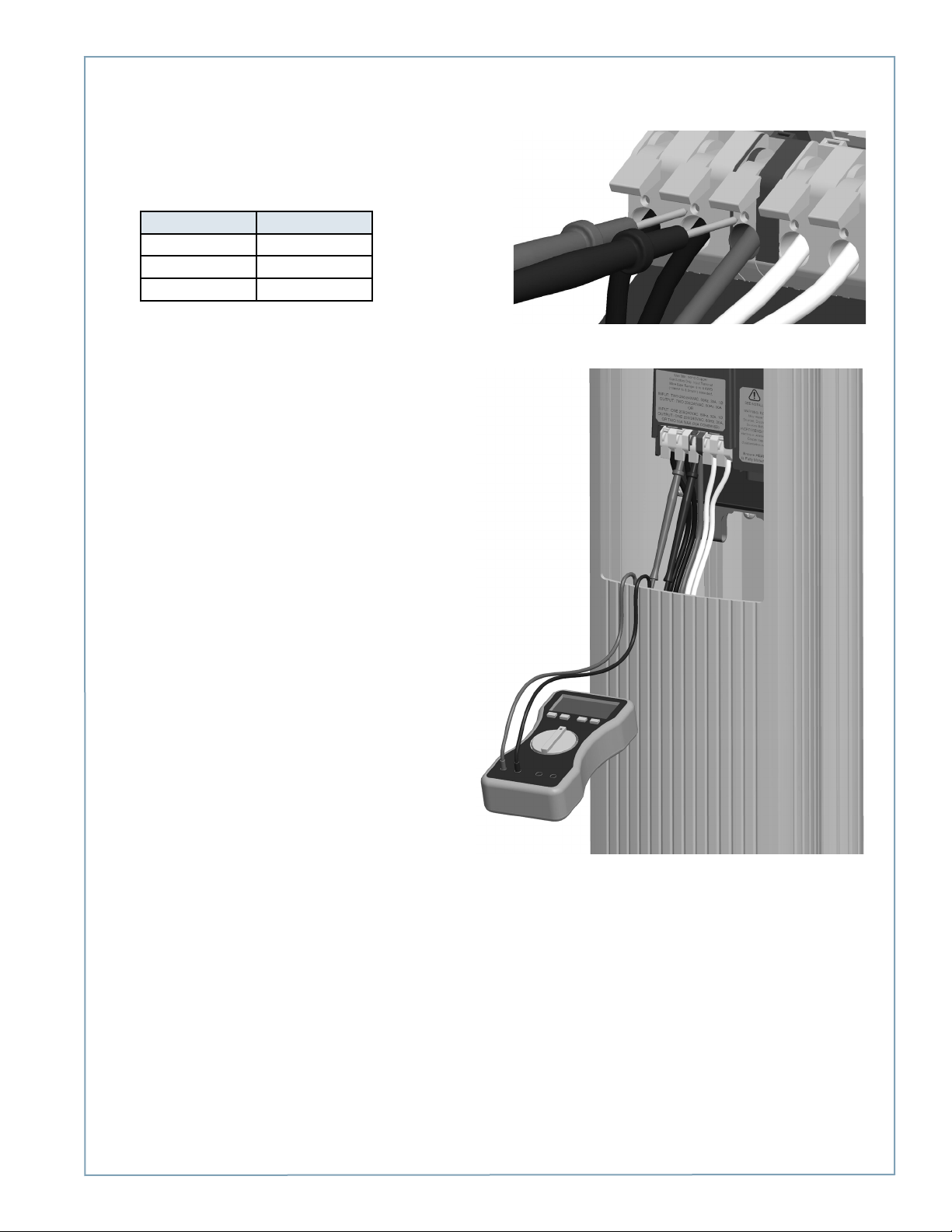
Step 8: Check Voltages
• Turn power ON.
• Using a solenoid type voltage tester, check that the
voltages at the charging station’s terminal block are
as follows:
Measure Between Volts
L1 and L2 208/240
GND and L1 120
GND and L2 120
If the voltages are not as expected, ensure that the
wiring has been properly connected as describing
on the previous page. For detailed wiring diagrams
and grounding requirements, see pages 1-4
to 1-6.
Before continuing, resolve any wiring issues and
ensure that voltages are as expected.
• Turn power OFF.
Installing a Bollard Mount
2-9
Page 20
ChargePoint® Charging Stations
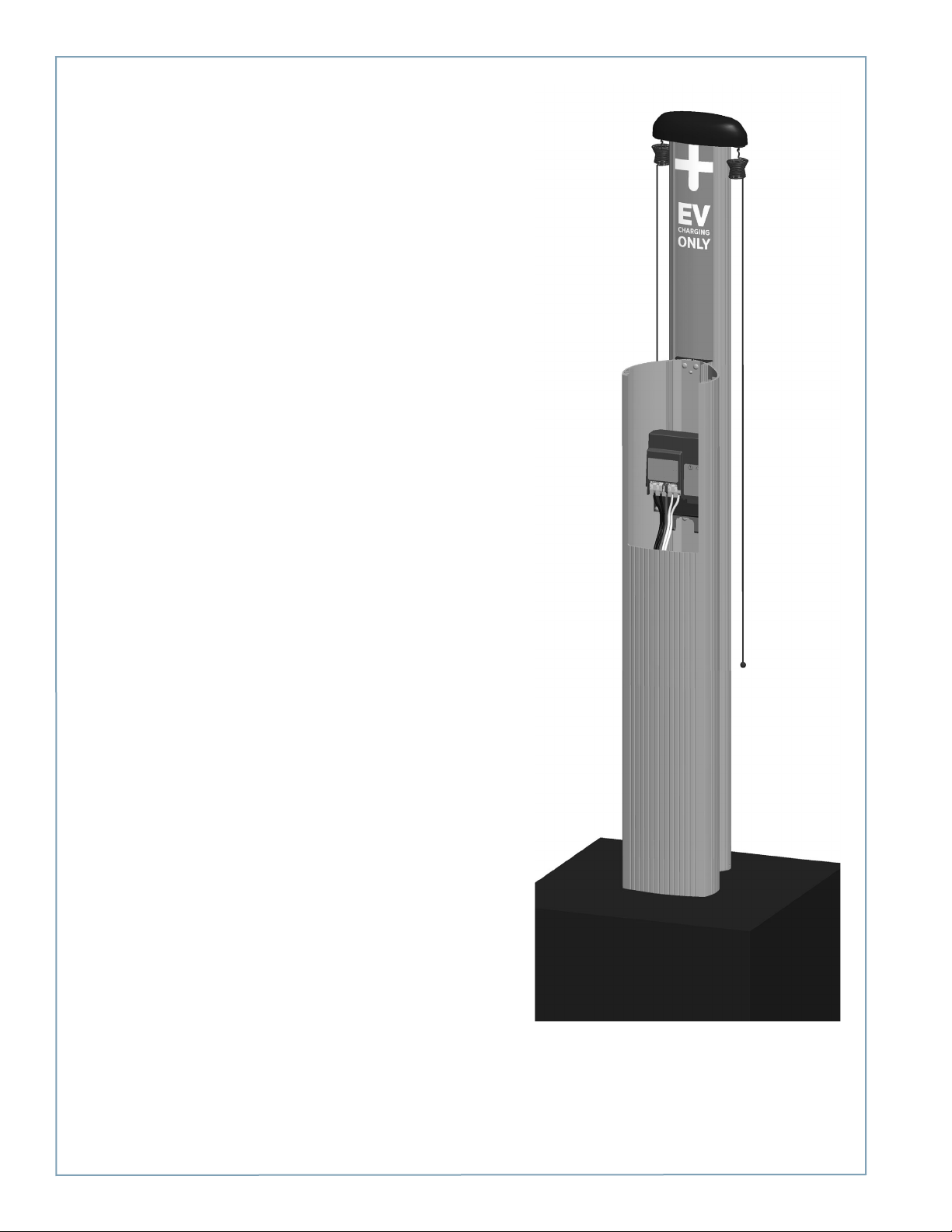
You have now finished installing the bollard mount and are ready to
install the head assembly and top cap. See Chapter 4.
2-10
Page 21

Installing a Wall Mount
Before You Start
You need the following:
• Drill and Tap for appropriate wall attachment hardware
• Attachment hardware, such as 3/8” (9.5 mm) x 3” (76 mm) lag bolts if mounting to a wood wall
• Ratchet and 9/16” deep socket
• #2 Phillips screwdriver
• Tape measure
• Bubble level
• Marker
• Wire stripper
• Multimeter
Overview of Steps
Installing the wall mount involves a few simple steps, summarized below and detailed in the remainder of this chapter:
1. Check Boxes for Correct Contents (page 3-2)
2. Drill Holes in Wall (page 3-3)
3. Mount Rear Brackets to Wall (page 3-4)
4. Prepare Retractor for Mounting (page 3-5)
5. Mount Retractor (page 3-6)
6. Install Conduit (page 3-7)
7. Install Main Body (page 3-8)
8. Connect Wiring (page 3-9)
9. Check Voltages (page 3-10)
When you have completed these steps, you will be ready to install the head and top cap as described in Chapter 4.
3
3-1
Page 22
ChargePoint® Charging Stations
Step 1: Check Boxes for Correct Contents
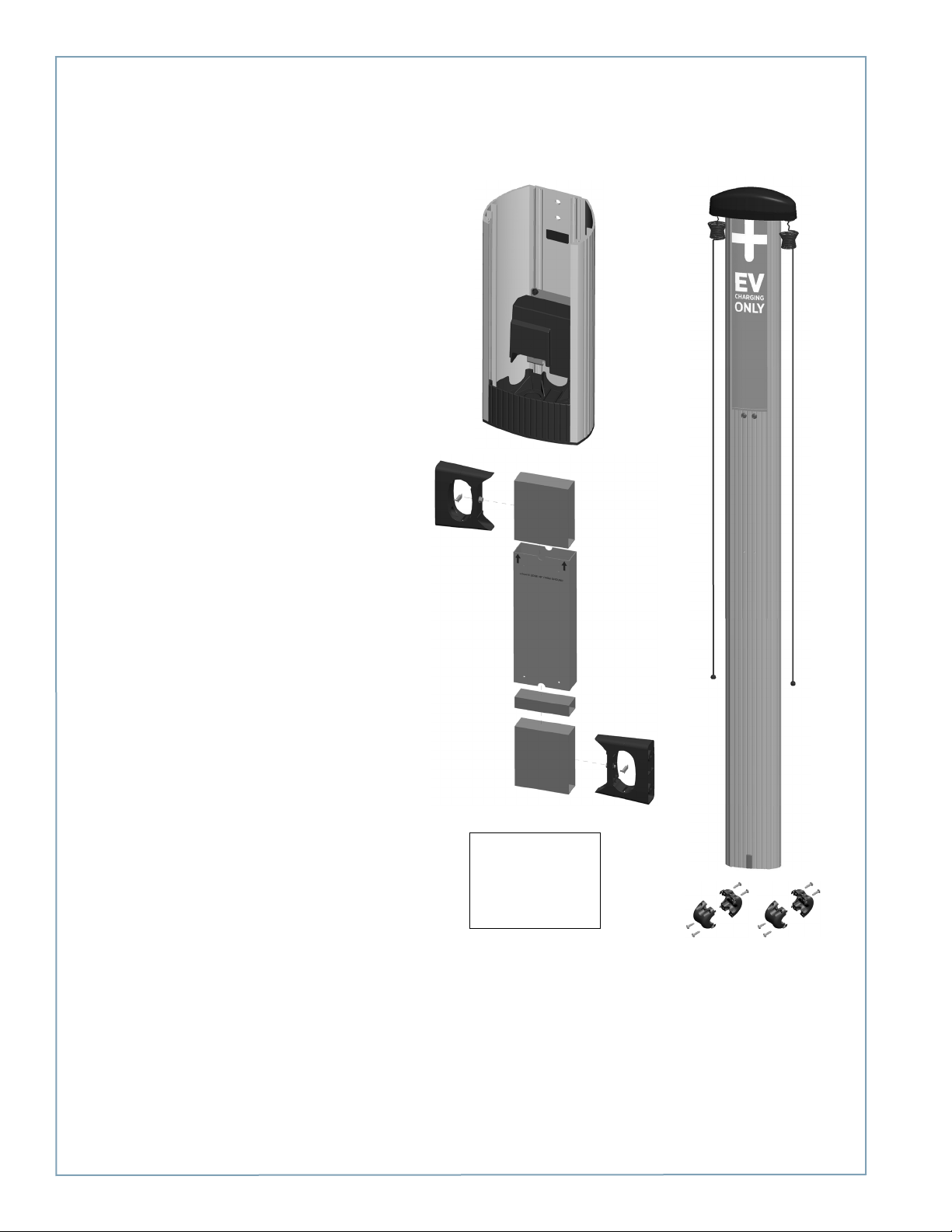
The wall mount ships in two boxes as described below.
Main Body and Mounting Kit
• Main body, pre-assembled (1)
• Mounting brackets with pre-installed screws and
flange bolts (2 sets)
NOTE: The packing box for the brackets serves as a
template for drilling mounting holes. Do not discard
packaging until you’ve completed Step 2.
• Slot cover (2)*
• Power sharing kit (use only if installing a dual-port
station on a single 40A circuit) (1)
*One extra slot cover is included.
Cable Management Kit
• Retractor assembly (1)
• Cable clamps (4)
• Phillips screws (10**)
**Two extra screws are included.
Main Body and Mounting Kit
Cable Management Kit
3-2
Page 23
Step 2: Drill Holes in Wall
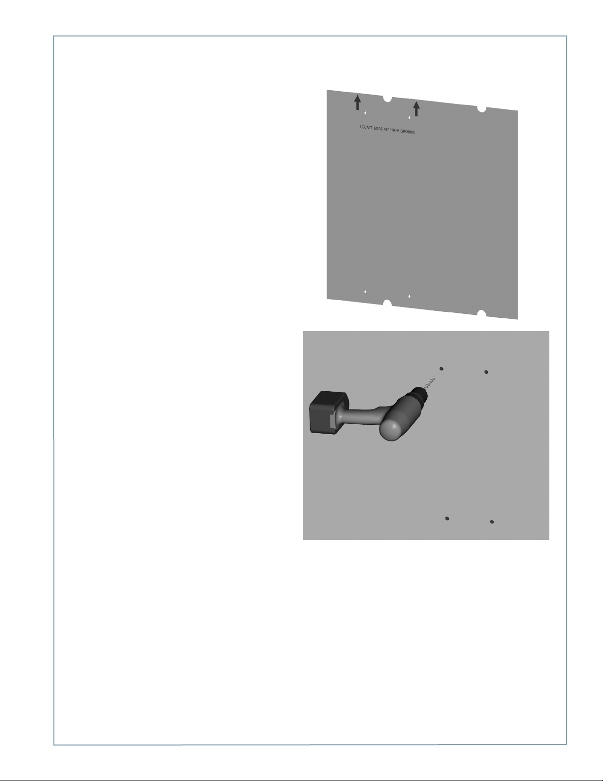
• The packing box for the brackets is used as a
template for drilling the wall holes. Tear the packing
box along the perforation to allow it to lay flat.
• Place the template against the wall. As described on
the package insert, align the top where indicated, 49”
above the floor or ground. Ensure that the template
is level and the side of the packaging insert is plumb.
Mark the four mounting holes.
• Drill four holes in the wall at the marked locations.
NOTE:
• If mounting to a hollow wall, bridge at least two
studs using a 1 5/8” channel strut. For wood studs,
use 3/8” (9.5 mm) lag bolts that are long enough to
penetrate at least 2 1/2” into the stud. Then mount
the supplied brackets to the channel strut using 3/816 x 1” long bolts, 3/8 ID x 13/16” OD washers, and
3/8-16 channel strut nuts.
• If mounting to a masonry wall, use 3/8” (9.5 mm)
expanding masonry fasteners.
• If mounting to a wood wall, use 3/8” (9.5 mm) x 3”
(76 mm) lag bolts.
Installing a Wall Mount
3-3
Page 24
ChargePoint® Charging Stations
Step 3: Mount Rear Brackets to Wall
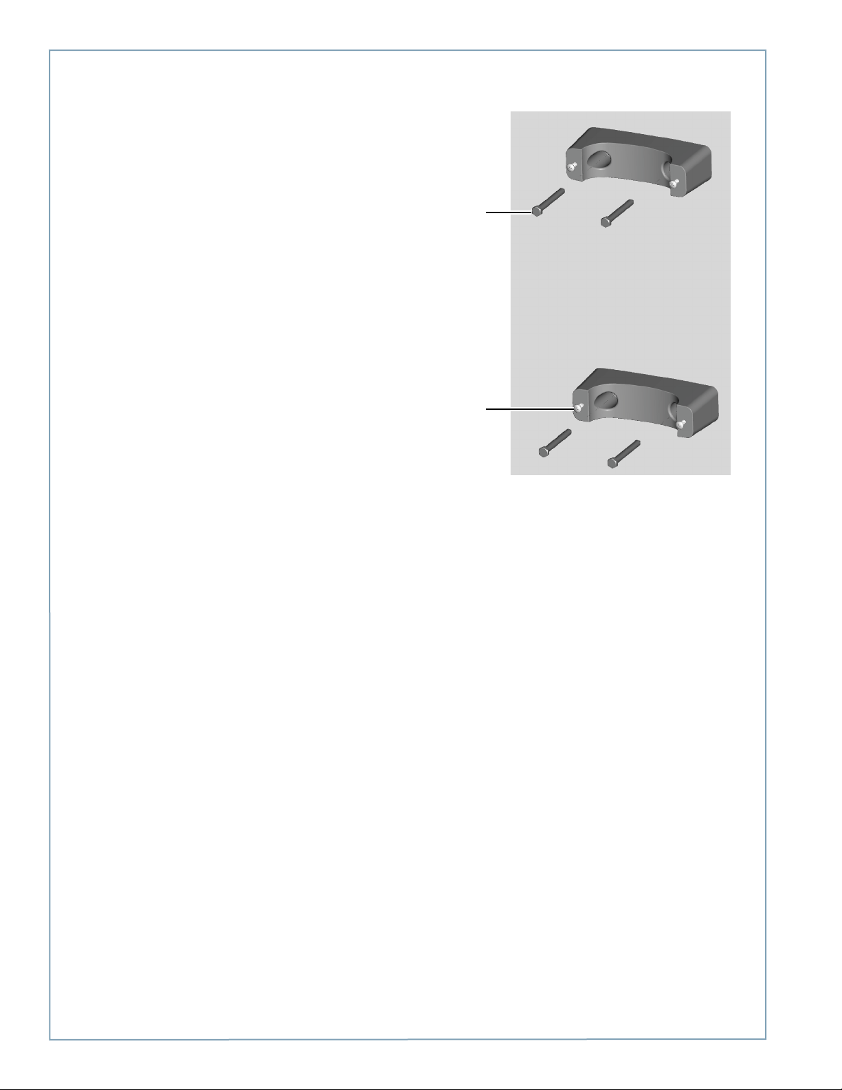
Mount each bracket to the wall using screws appropriate
for the type of wall material.
Partially insert the 1/4” - 20 screws into the rear brackets.
Do not fully insert these screws—leave about 3/4”
protruding.
Mount brackets
using screws
appropriate for type
of wall material (not
supplied)
Partially insert
the four supplied
1/4”-20 screws
3-4
Page 25
Step 4: Prepare Retractor for Mounting
Installing a Wall Mount
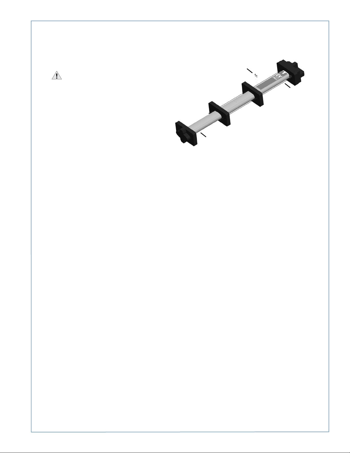
To prepare the retractor for mounting:
• Position the retractor packaging so that the bottom
of the retractor is near the bottom of the wall.
IMPORTANT: Do not unwrap the cords.
• Remove and discard the two shipping screws from
the front face of the retractor.
NOTE: When you remove the shipping screws, the
retractor’s counterweights are free to move in either
direction. Therefore, do not tilt or carry the retractor
assembly with the top end lower than the bottom
end.
• Remove the foam packaging from the retractor.
• OPTIONAL: If necessary, remove or replace the EV
PARKING sign. See Appendix B.
Bottom
Discard
shipping
screws
Top
When handling, always
keep the top end higher
than the bottom end.
3-5
Page 26
ChargePoint® Charging Stations
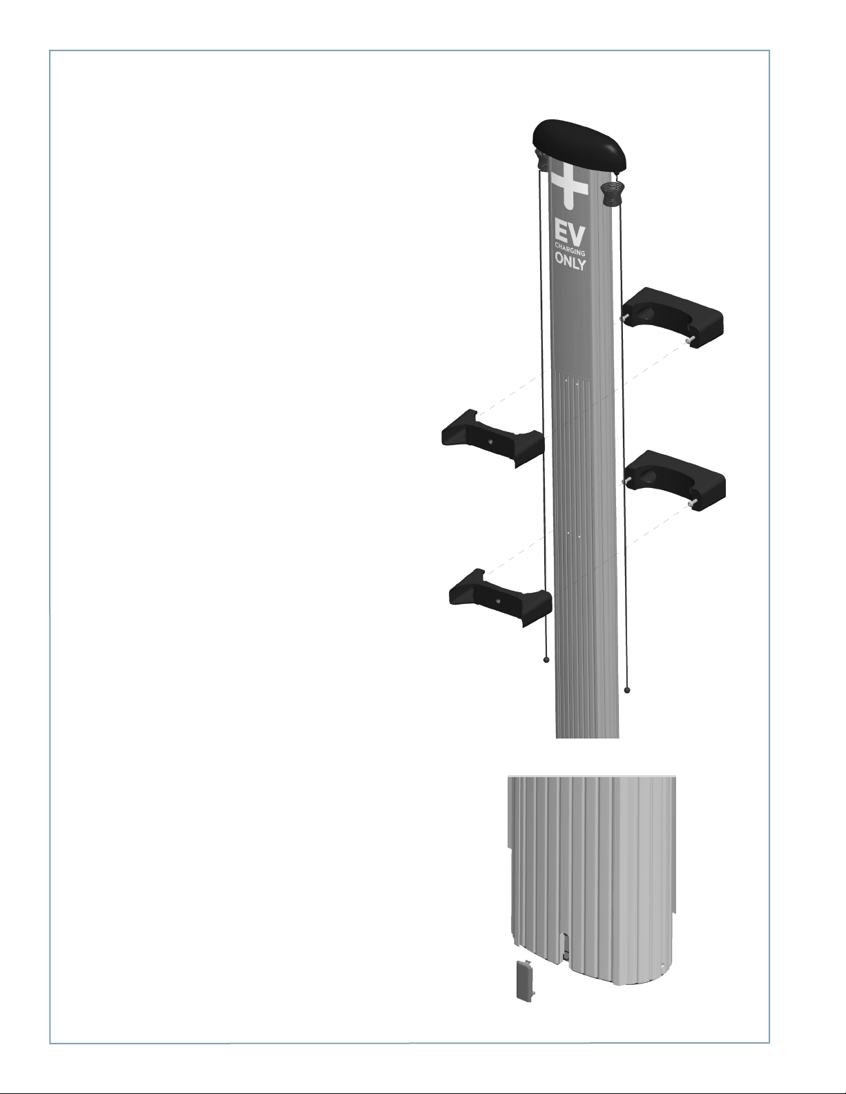
Step 5: Mount Retractor
To mount the retractor assembly:
• Place the two front brackets where you can easily
reach them.
• Tilt the retractor up against the rear brackets, with
the front of the retractor facing towards you, as
shown (mount holes visible).
NOTE: The bottom of the retractor should rest on the
ground.
• Place the top front bracket over the two
corresponding screws protruding from the top rear
bracket. You’ll need to steady the retractor with one
hand, while using the other hand to position the
bracket.
• Repeat for the bottom bracket.
• Tighten all four screws to 60 in-lbs using the Phillips
screwdriver.
• Insert the slot cover, bottom first, into the slot at the
bottom of the retractor.
3-6
Page 27
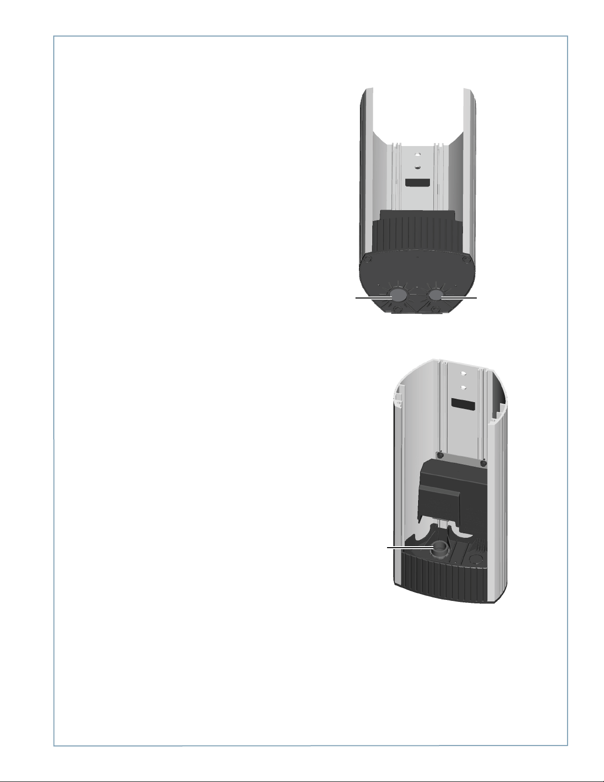
Step 6: Install Conduit
As shown, the base of the main body has two conduit
knockouts: 1” and ¾”. Using a flat screwdriver, remove the
knockout that suits your installation needs.
Installing a Wall Mount
1” knockout
Install and seal conduit.
Follow local codes.
3/4” knockout
3-7
Page 28
ChargePoint® Charging Stations
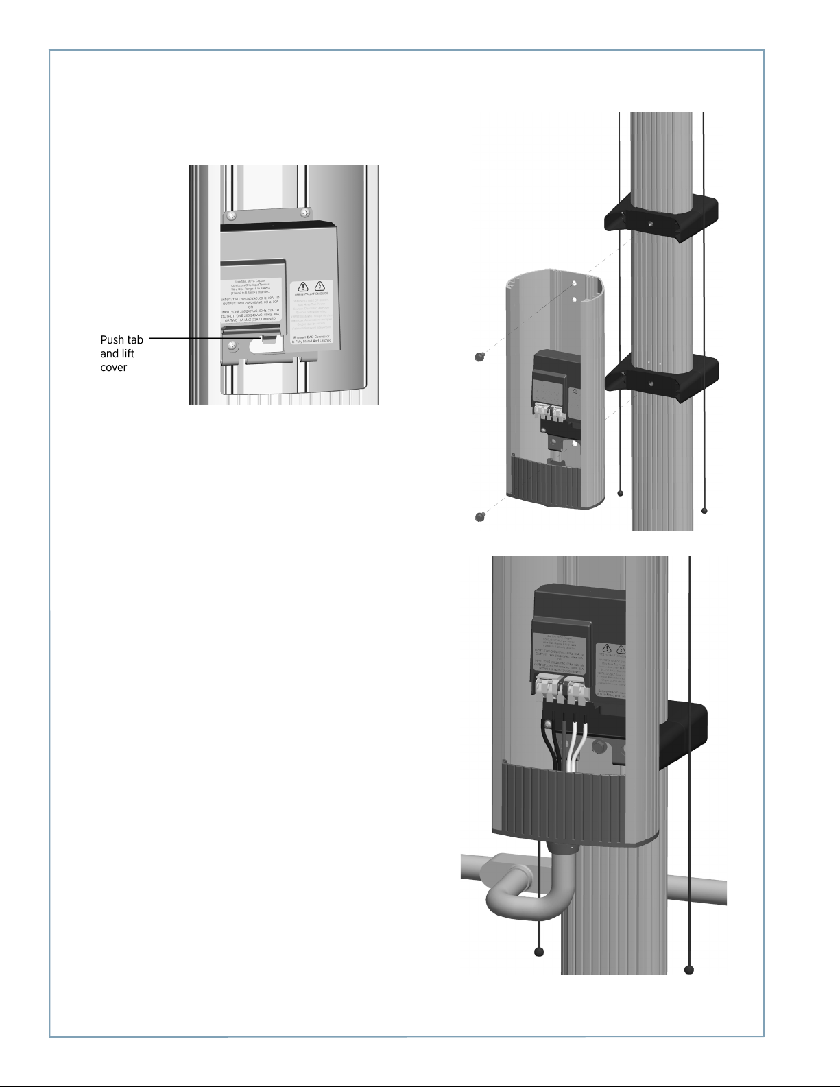
Step 7: Install Main Mody
• Expose the pre-drilled hole located below the terminal
block. To do so, push the tab on the terminal block to
release the cover plate, then slide the cover plate upwards:
• Position the main body so that the top hole aligns with
the top retractor bracket.
• Insert a 3/8 - 16 x 3/4” flange bolt into the top hole and
finger tighten.
• Insert the other flange bolt into the lower mounting hole.
• Tighten both flange bolts to 150 in-lbs.
• Connect the conduit and run wiring through the conduit
and into the main body of the station.
3-8
Page 29
Installing a Wall Mount
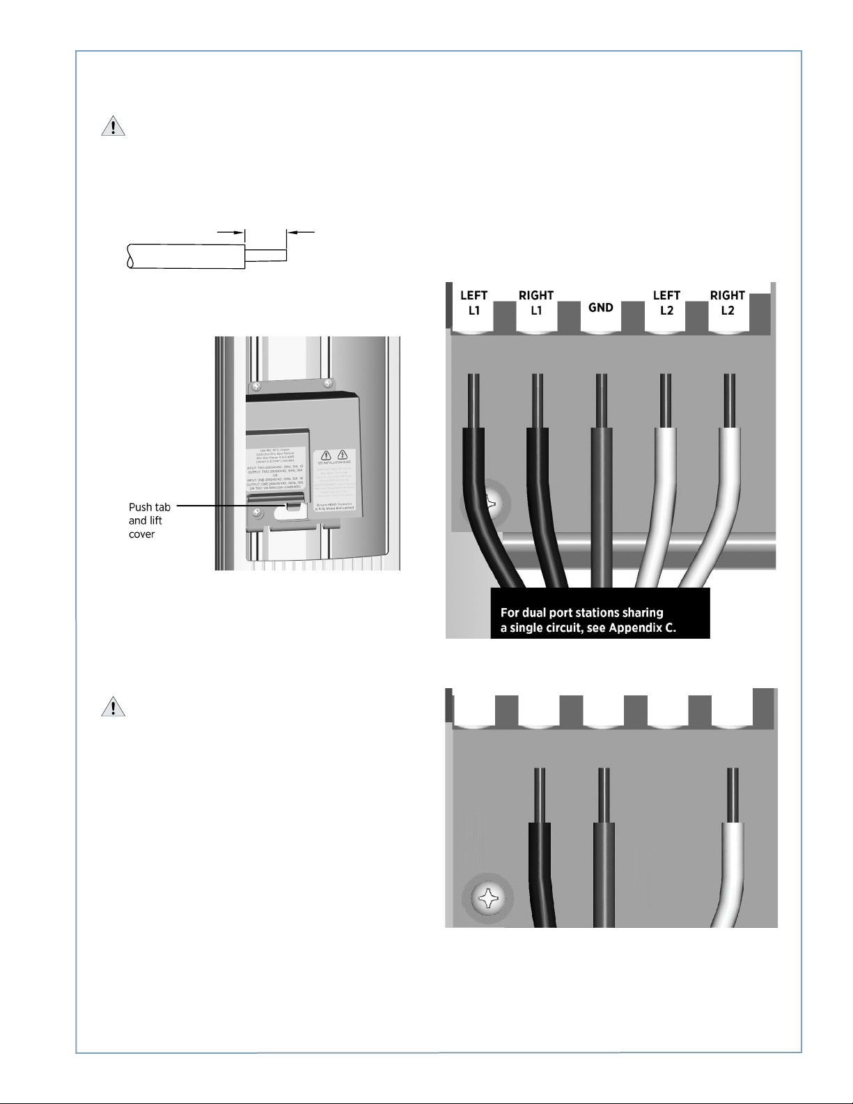
1/2” (13 mm)
Step 8: Connect Wiring
IMPORTANT: To power a dual-port station using a single 40A circuit, use the Power Sharing Kit (CT4020-PSHARE)
provided in the shipping box with the main body. Instead of following the instructions below, see Appendix C. You must also
manually configure the station for power sharing, as described in Appendix C.
If you are not installing a power sharing kit, connect the wiring as follows:
• Strip wires ½” (13 mm).
• Push the black tab on the terminal block to release the
terminal block cover, then slide the cover up until it locks
into the raised position:
• Lift the corresponding white lever on the terminal block,
insert the ground wire into the center connector, then
push the lever down until it clicks into its fully closed
position.
• Lift the corresponding white levers, insert the 240 VAC L1
and L2 wires, then push the levers down until they click
into their fully closed position.
WARNINGS:
• Use copper conductors only.
• Do NOT provide GFCI protection at panel. The CT4000
has built-in GFCI protection.
• In areas with frequent thunder storms, add surge
protection at the service panel for all circuits.
• Use new circuit breakers only. Used breakers can
damage equipment and introduce the potential for an
electrical fire.
• Ensure all power and ground connections, especially
those at the breaker and buss bar, are clean and tight.
Remove all oxide from all conductors and terminals
before connecting wiring.
For dual port stations:
For single port stations, use the connectors indicated for “RIGHT” side only.
LEFT
L1
RIGHT
L1
GND
LEFT
L2
RIGHT
L2
3-9
Page 30
ChargePoint® Charging Stations
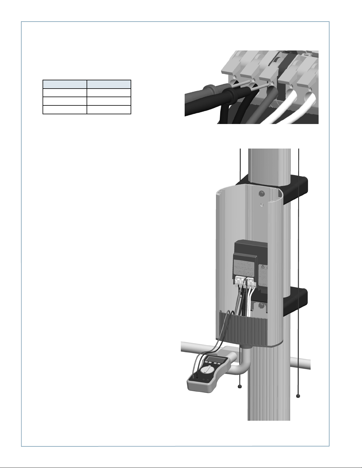
Step 9: Check Voltages
• Turn power ON.
• Using a solenoid type voltage tester, check that the
voltages at the charging station’s terminal block are as
follows:
Measure Between Volts
L1 and L2 208/240
GND and L1 120
GND and L2 120
If the voltages are not as expected, ensure that the
wiring has been properly connected as describing
on the previous page. For detailed wiring diagrams
and grounding requirements, see pages 1-4
to 1-6.
Before continuing, resolve any wiring issues and ensure
that voltages are as expected.
• Turn power OFF.
3-10
Page 31
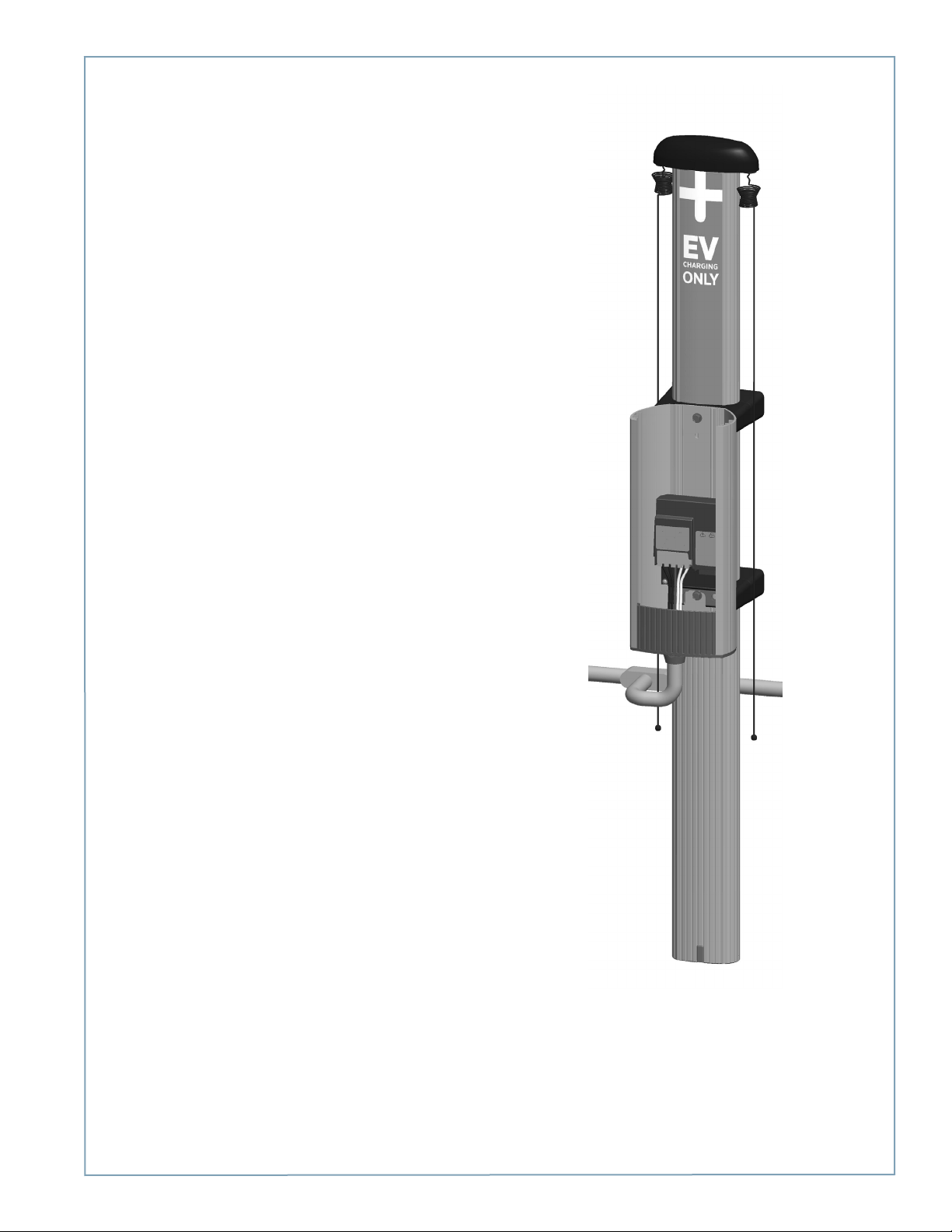
You have now finished installing the wall mount and are ready to
install the head assembly and top cap. See Chapter 4.
Installing a Wall Mount
3-11
Page 32

Page 33

Installing the Head and Top Cap
Before You Start
Before installing the head and top cap, you must complete the installation of the main body and its cable management
system as described in a previous chapter. You need the following:
• Wire cutter
• #2 Phillips screwdriver
Overview of Steps
Installing the head and top cap involves a few simple step, summarized below and detailed in the remainder of this chapter:
1. Check Boxes for Correct Contents (page 4-2)
2. Prepare Head Assembly for Mounting (page 4-4)
3. Slide Head Assembly into Body (page 4-6)
4. Connect Head Assembly (page 4-7)
5. Verify the Station Operates Correctly (page 4-10)
6. Install Cable Clamps (page 4-10)
7. Secure Head Assembly (page 4-11)
When you have completed these steps, you will be ready to prepare the station for activation on ChargePoint, as described in
Chapter 5.
4
4-1
Page 34
ChargePoint® Charging Stations
Step 1: Check Boxes for Correct Contents
Top cap
The station’s top cap ships in a box containing:
• Top cap (1)
• Phillips screws (2)
• CT4000 Installation Guide (this document)
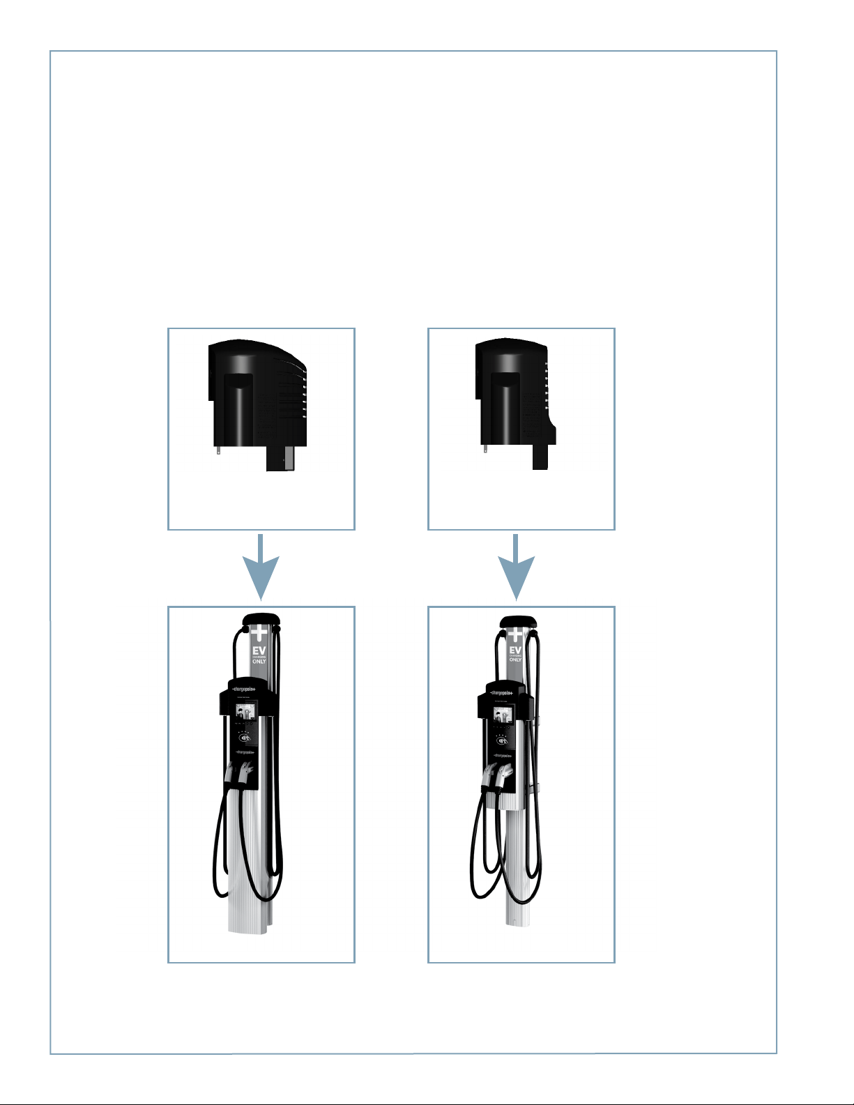
As illustrated below, the shape of the top cap depends on whether you are installing a bollard or a wall mount. The bollard
mount’s top cap is more rounded, whereas the wall mount’s back is flatter. If installing both models, pay particular attention
to the top cap’s shape.
Side view
(rounded back)
Side view
(flat back)
4-2
Bollard
Wall Mount
Page 35
Step 1 cont’d: Check Boxes for Correct Contents
Head assembly
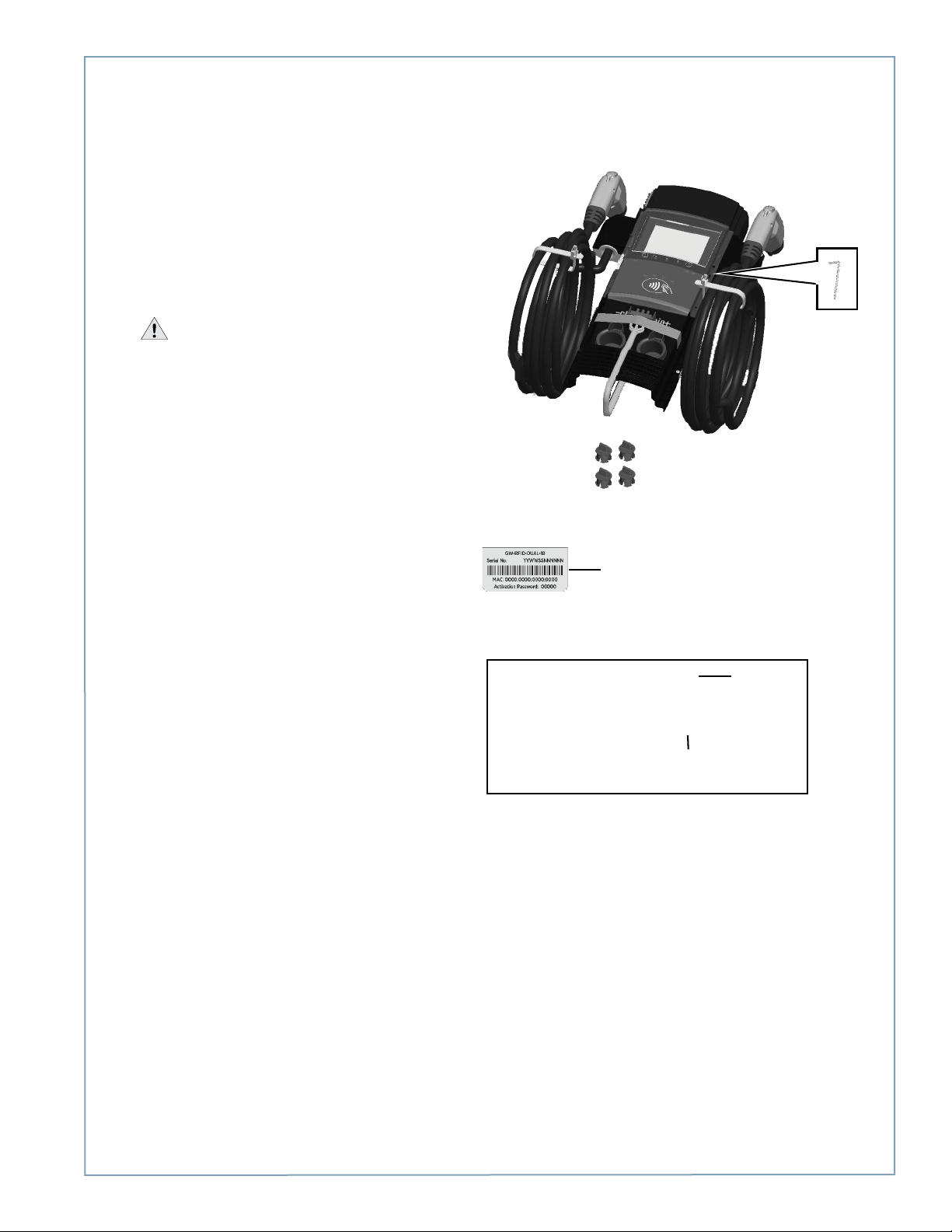
The station’s head assembly ships in a box containing:
• Head assembly
• Rubber plugs (4) - two of these are spares.
• T25 Allen wrench (attached with a security tag on
the side of the head assembly)
• Spare activation label (a duplicate label is attached
to the head assembly)
IMPORTANT: Keep the spare activation label
for future reference. It contains critical information
that is needed to document the radio groups when
preparing the station for activation on ChargePoint
(see page 5-5).
For gateway stations, a Network Enablement Kit is also
included:
• SIM card
• Installation instructions
Installing the Head and Top Cap
An activation label is attached to the
head assembly. This duplicate label is
provided to simplify the step of
documenting the radio groups, as
described in Chapter 5. It includes
important information needed to
activate the station on ChargePoint.
GATEWAY STATIONS ONLY:
The shipping box also
includes an envelope
containing the Network
Enablement Kit.
SIM card
Installation
instructions
4-3
Page 36
ChargePoint® Charging Stations
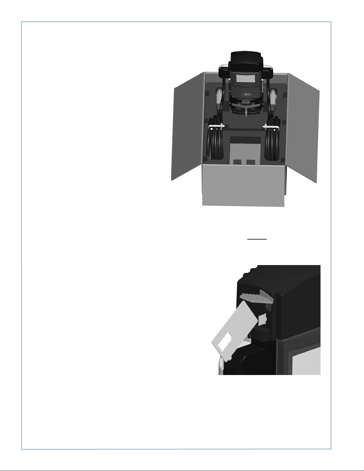
Step 2: Prepare Head Assembly for Mounting
• To prepare the head assembly for mounting, open
the box and stand the head upright on its foam
packaging, as shown.
• If you are installing a gateway station, install the
Network Enablement Kit:
a) Remove the SIM card from its carrier by pushing
it firmly.
a) Lift the rubber flap located on the right hand side
of the head assembly, as shown.
b) Insert the notched edge of the SIM card into the
slot, with the notch facing upward. Slide it into the
slot and push it FULLY into the slot until it “clicks”
into place. Refer to the orientation instructions
printed on the side of the head assembly.
TIP! To push the SIM card into the slot, use a corner
of the SIM card’s carrier, as shown.
Remove the SIM card
4-4
Page 37
Installing the Head and Top Cap
Step 2 cont’d: Prepare Head Assembly for Mounting
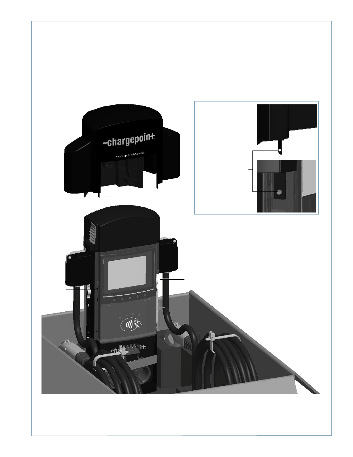
• Install the top cap
a) Place the top cap over the head assembly as shown, ensuring correct alignment.
b) Using a Phillips screwdriver, secure the top cap to the head assembly by inserting the two supplied screws into the
back of the top cap and tightening to 20 in-lbs.
Ensure correct alignment
so the top cap slides into
its secured position:
The small hole in each
of the two protruding
tabs on the bottom of
the top assembly must
slide and then snap
over the corresponding
Tab
Tab
nodule on the side of
the head assembly.
Nodule
Nodule
4-5
Page 38
ChargePoint® Charging Stations
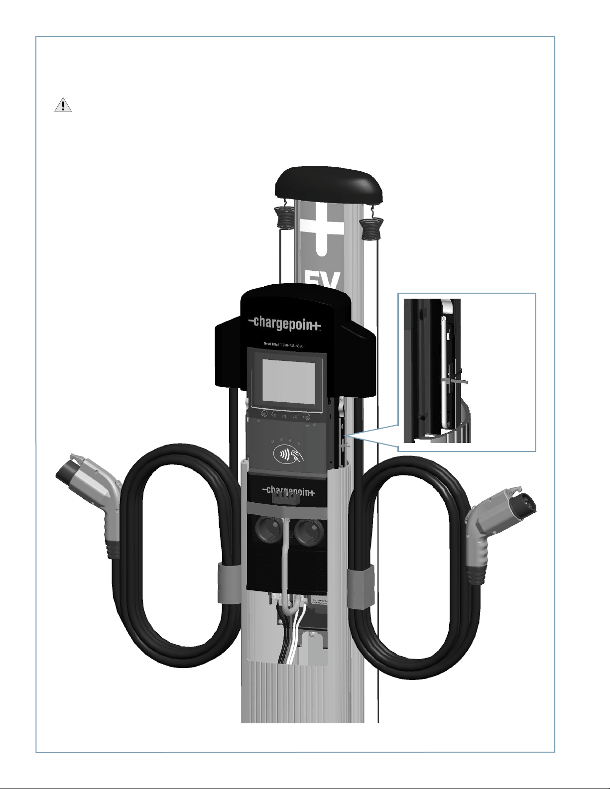
Step 3: Slide Head Assembly Into Body
Slide the head assembly into the main body until it is stopped by the head assembly’s security tag.
IMPORTANT: Do not insert the charging connectors into the holsters until after you’ve powered up the station. Doing so
causes the holsters to permanently lock.
The security
tag on the
side of the
head
assembly
prevents it
from sliding all
the way into
the body
4-6
Page 39
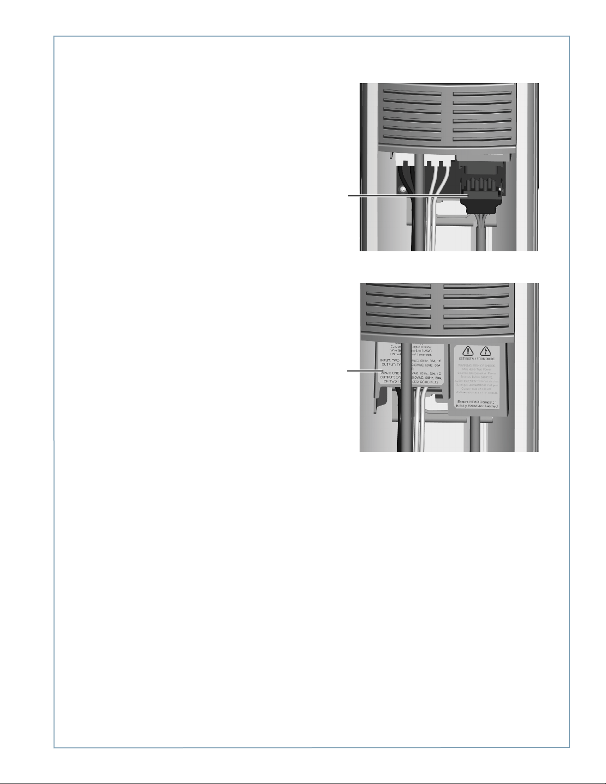
Step 4: Connect Head Assembly
Pull to remove the yellow strap from the blue connector.
Connect the blue connector to the terminal block,
ensuring it “clicks” into place.
Push the cover down over the terminal block.
Installing the Head and Top Cap
The blue
connector
“clicks” into
place on the
terminal block
Push the
cover down
over the
terminal
block
4-7
Page 40
ChargePoint® Charging Stations
Step 5: Verify the Station Operates Correctly
Before securing the head assembly, follow these steps to verify that the station is fully operational.
IMPORTANT: if the station is not operating as described below, see “Chapter 6, Troubleshooting” to resolve the error
before continuing.
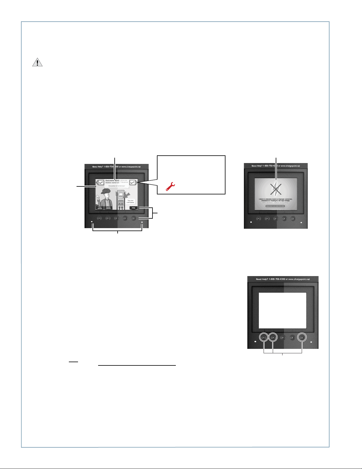
1. When the station is powered on, you should see:
• The instructional video, and no error messages.
• The status icon for each port displaying a green check mark.
• neither of the two error LEDS light up (for some errors, these LEDs are solid or blinking red).
NOTE: If the station does not power up, check that the head assembly’s rectangular connector is properly seated onto
the terminal block.
Under normal
conditions, the
station displays
the instructional
video
For some errors, this top
banner displays an error
message instead of station
information
For some errors, one or both
error LED(s) will appear solid or
blinking red
The status icon for each port
should display a green check
mark. If these icons appear, the
port (or station) has an error:
Choose a menu
option by pressing
the button below it
In some cases, a static error
message fills the entire display
2. Even if the station’s display and LEDs show no indication of an error, always display station codes to confirm that no
errors exist. To display station codes:
a) Activate the Service Menu by simultaneously pressing and holding the two
leftmost buttons and the rightmost button for two seconds.
b) Press the station button immediately below the “HELP” menu option.
c) Press the station button immediately below the “DOWN” menu option to
highlight “Station Codes”.
d) Press SELECT.
This port is
displaying a
station code
If you see a station code, you must resolve or report the error before leaving the installation site. Station codes are
described in “Chapter 6, Troubleshooting.”
4-8
This port is not
displaying a
station code
Simultaneously press and hold
these three buttons for two
seconds to display the Service
Menu on an unactivated station
Page 41

Installing the Head and Top Cap
Step 5 cont’d: Verify Station Operates Correctly
3. Use the ChargePoint card attached to the front cover of this Installation Guide to authorize a charging session. Make sure
that both plug holsters unlock and that the station displays instructions on how to plug into the vehicle.
NOTE: The ChargePoint card supplied on the front cover can authorize up to ten charging sessions.
If you have performed the above steps, and the station operates as described and no errors exist, continue with the
installation. If any of the above conditions are not met, resolve the error before continuing by referring to Chapter 6,
Troubleshooting.
4-9
Page 42
ChargePoint® Charging Stations
Step 6: Install Cable Clamps
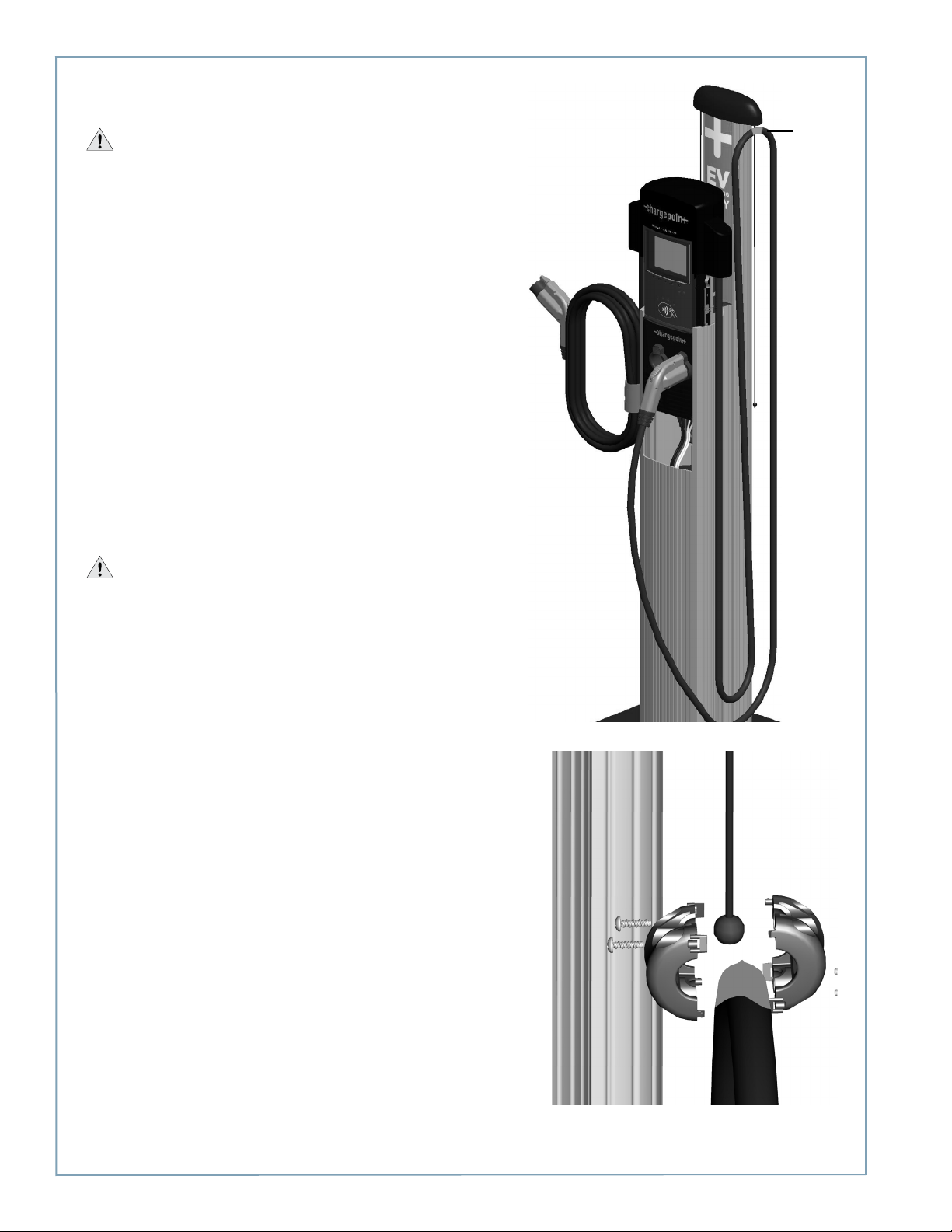
IMPORTANT: Do not unwrap the ropes until they are securely
attached to the charging cable.
To install the cable clamps:
• Locate the bead at the end of the retractor rope.
• Uncoil the charging cable by removing the plastic wrap, then
gently extending it all the way out, away from the station. Rotate
the plug as necessary to remove any twists or kinks. Locate the
tape that marks the position where the clamp attaches to the
cable.
• Hold the charging cable with the marked tape positioned under
the retractor top, as shown. Ensure the charging cable does not
touch the ground when fully retracted.
• Insert the bead inside the clamp, then snap the opposite side of
the clamp into place.
• Secure the two sides of the clamp together by inserting the four
screws and tightening them securely using a Phillips screwdriver.
• Repeat the above steps for the other charging cable (if
applicable). If installing a single port station, allow the left
(unused) rope fully retract into the top cap.
• Pull down on the rope and remove the rope from its wrapper.
When the rope is unwrapped, it retracts into the top cap.
Position
tape under
retractor
top
IMPORTANT: Check that the charging cable extends and
retracts fully and smoothly. If it doesn’t, see page 6-5.
4-10
Page 43
Step 7: Secure Head Assembly
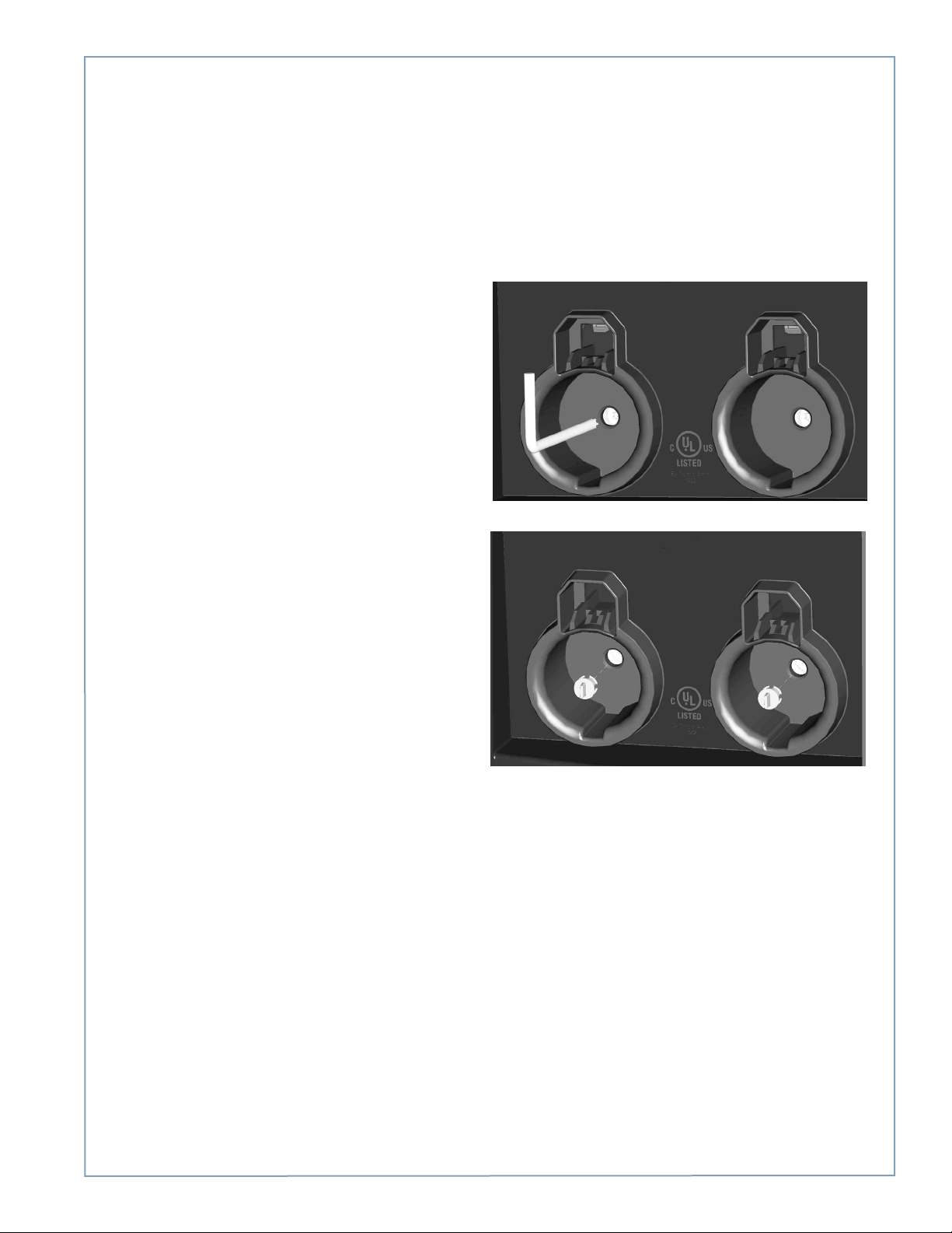
To secure the head assembly:
• Remove the T-25 L-wrench by rotating it to the right
until the security tag breaks. Lift the head assembly
slightly and remove the L-wrench.
• Lower the head assembly. Ensure the head assembly
is fully seated and that no gap exists between the
bottom of the head assembly and the main body.
The head assembly fits tightly and may require extra
downward force to ensure it is fully seated.
• Using the T25 L-wrench, tighten the two security set
screws, located inside the holsters, to approximately
25 to 30 in-lbs.
Installing the Head and Top Cap
• Cover the screws using the two rubber plugs.
• Insert the charging plugs into their corresponding
holsters.
You have now finished the physical installation of the CT4000 charging station and are ready to prepare the station for
activation on ChargePoint. See Chapter 5.
4-11
Page 44

Page 45

5
Preparing the Station for Activation on ChargePoint
Before You Start
Before leaving the installation site, you must prepare the station for activation. You need the following:
• a laptop or tablet computer
• installer user name and password for www.chargepoint.com
Overview of Steps
Preparing the station for activation on ChargePoint involves a few simple steps, summarized below and detailed in the
remainder of this chapter:
1. Pinpoint the Station (page 5-2)
2. Document the Radio Groups (page 5-5)
3. Complete the Post-installation Checklist (page 5-6)
When you have completed these steps and provided the necessary information to the person responsible for activating the
station on ChargePoint, the installation of the CT4000 charging station is complete.
5-1
Page 46

ChargePoint® Charging Stations
Step 1: Pinpoint the Station
Follow these steps to pinpoint the station on ChargePoint.
1. Log in to ChargePoint; then, on the Manage Stations tab, click Pinpoint New Station.
Manage Stations
Pinpoint New Station
2. Enter the station’s MAC Address and activation password, then click Verify.
NOTE: The station’s MAC Address and activation password is printed on a label that
has been taped to the front of the head assembly. A label is also affixed to the head
assembly itself, but once the head assembly has been installed, you can no longer see
it.
5-2
Page 47
Preparing the Station for Activation on ChargePoint
Step 1 cont’d: Pinpoint the Station
3. Enter the station’s physical location.
a) In the search field above the map, enter the station’s physical address, then click the magnifying glass. You can enter
a full or partial address—you will pinpoint the exact location of the charging station in the next step.
Enter the address, then click the magnifying glass
b) Change to Satellite View and drag the pinpoint to the parking spot where the station is located.
Click here for Satellite View
NOTE: A station’s address and
physical location may vary
slightly. The goal is to make it
easy to identify the station’s
location on a Google™ map.
Therefore, be as accurate as
possible when pinpointing
a station’s location. This is
especially important when you
install multiple stations at the
same street address.
c) Click Update Address to accept the address shown to the right of the satellite image, or click Manually edit the
address to enter the correct address—one that will make sense to drivers.
d) In the Helpful Information for Drivers field, enter any information that will make it easier for drivers to find the
station. For example, “Back parking lot”, or perhaps “Second floor of parking garage, near mall entrance.”
4. Click Save and Activate Later.
5-3
Page 48

ChargePoint® Charging Stations
THIS PAGE INTENTIONALLY LEFT BLANK
5-4
Page 49
Preparing the Station for Activation on ChargePoint
Step 2: Document the Radio Groups
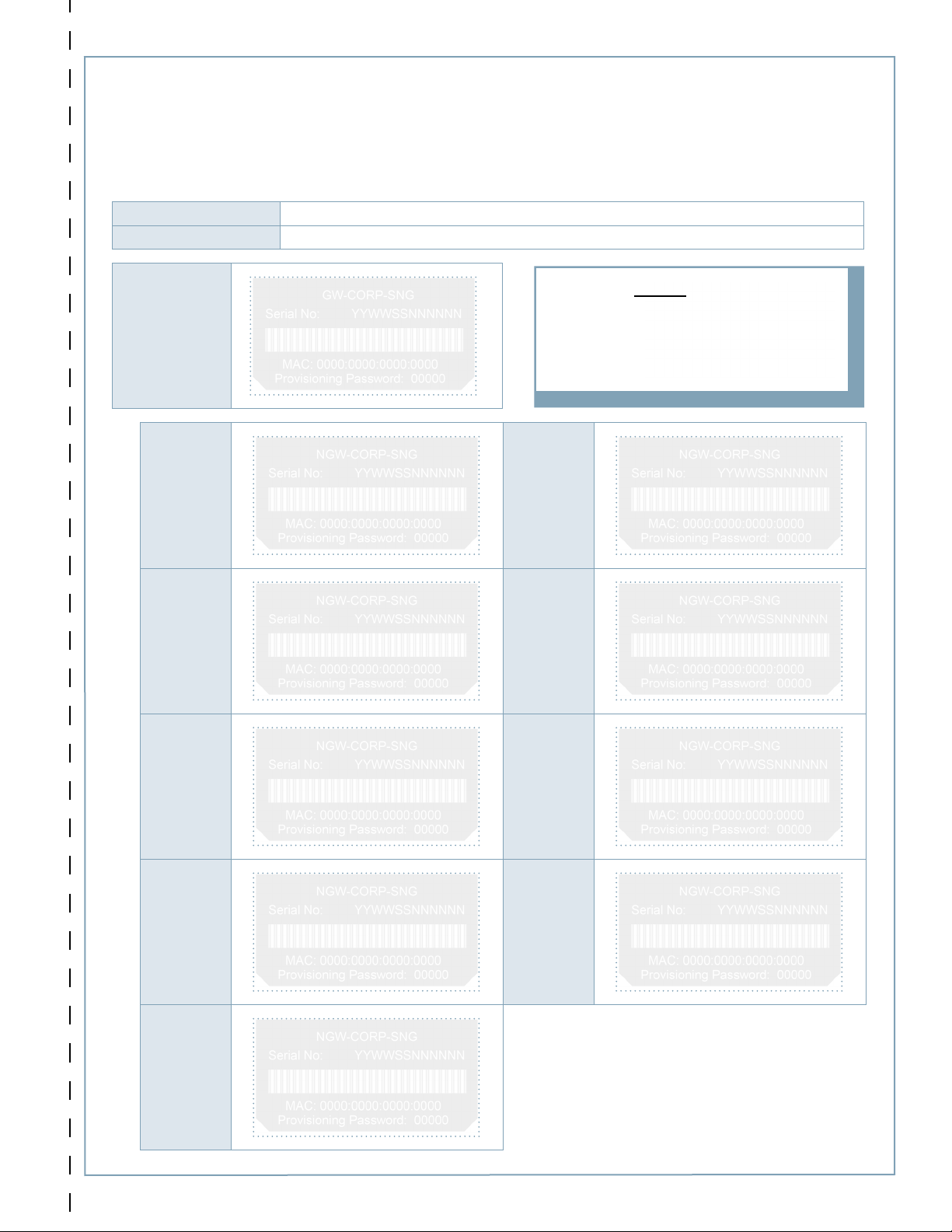
For each radio group, attach spare activation labels below to document how stations are organized. After completing the
next step on the reverse side, tear out this page and give it to the person responsible for activating the station. If installing
multiple radio groups, use one page for each radio group (this page is included in all CT4000 Installation Guides).
Customer Name
Site Address
NOTE:
Gateways begin
with “GW-”
Gateway
Peel off sticker and place here
Non-gateways
begin with “NGW-”
Non-gateway Non-gateway
Peel off sticker and place here
Non-gateway Non-gateway
Peel off sticker and place here
Non-gateway Non-gateway
Peel off sticker and place here
Non-gateway Non-gateway
Peel off sticker and place here
Peel off sticker and place here
Peel off sticker and place here
Peel off sticker and place here
Peel off sticker and place here
After completing both sides, cut or tear along dotted line and give it to the person responsible for activating the station.
"
Non-gateway
NOTE: A radio group consists of one
gateway station and up to nine non-gateways.
Peel off sticker and place here
5-5
Page 50
ChargePoint® Charging Stations
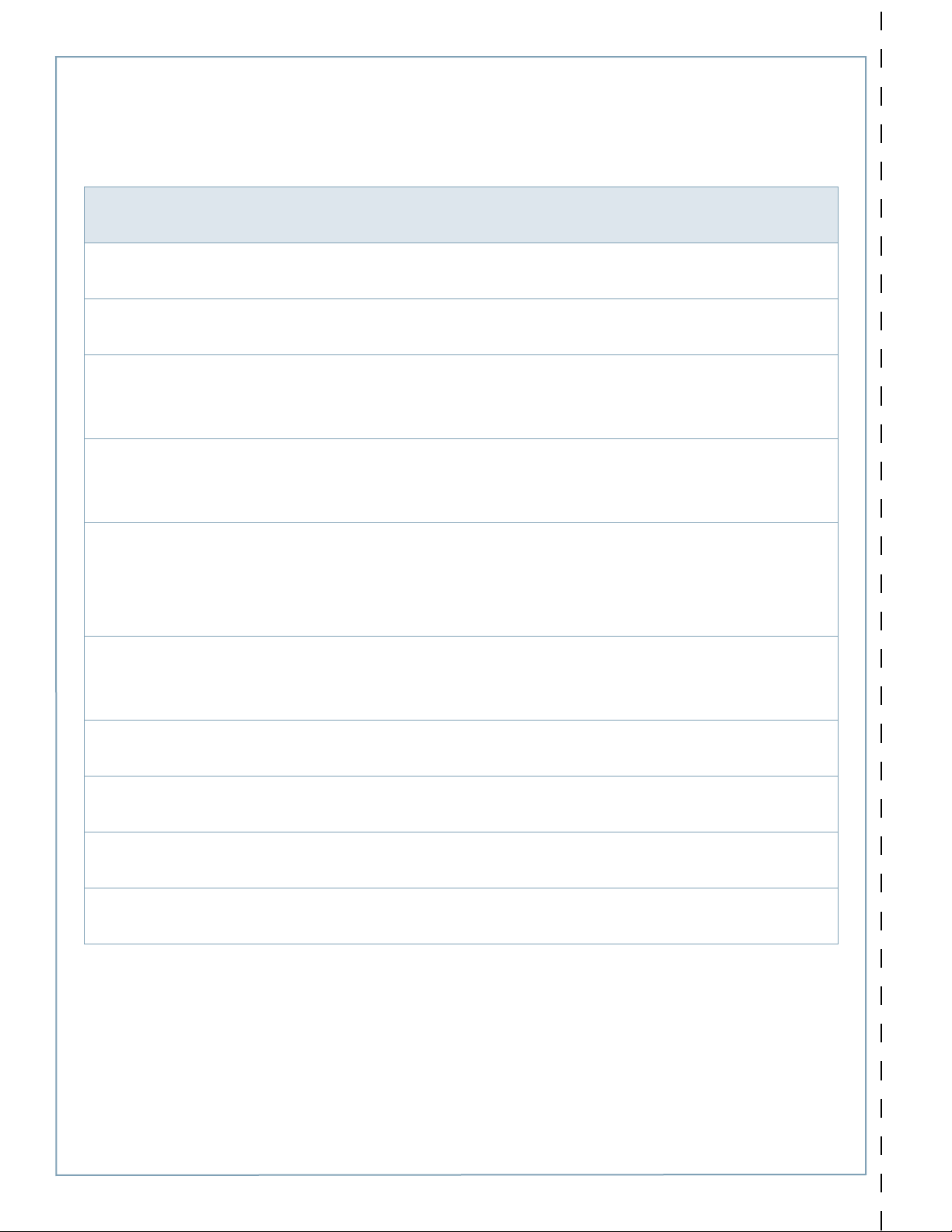
Step 3: Complete the Post-Installation Checklist
Before leaving the installation site, complete this checklist for each radio group. Then tear out this page and give it to the
person responsible for activating the station. If installing multiple radio groups, use one page for each radio group (this page
is included in all CT4000 Installation Guides).
Check each box below to confirm that the task has been completed for all stations within the radio group.
þ
All mounting hardware is tightly secured and all stations are level and rock solid.
¨
The two security screws inside the holster plugs on all head assemblies are tightened and the rubber plugs are in
¨
place.
Cable retractors:
• Cable clamp halves are screwed together with no gaps.
¨
• All charging cables operate smoothly through full extension and retraction.
Voltages at all power plates have been verified with a solenoid type voltmeter (such as a Wiggy):
• Line-to-Line measures 208/240VAC.
¨
• Line-to-Earth measures 120VAC.
If Power Share Jumpers are installed:
• All jumpers are fully inserted. Look for 1/8” (3 mm) depth.
• Power Share mode has been configured, using the stations’ Service Menu, for all power-shared stations and the
¨
station’s display indicates that power sharing is in effect.
• The supplied Electrical Rating label has been applied above the terminal block.
Check the station’s communications signal(s) (Help > Network) and ensure that the:
• LAN signal strength shows at least 2 bars on all stations.
¨
• WAN signal strength shows at least 2 bars (on the gateway station).
The Service Menu shows no station codes for either port (Help > Station Codes) on all stations.
¨
Start a charging session on all stations using a ChargePoint card (provided on the front cover of this Installation
¨
Guide). Ensure the station displays no error codes or warning lights and that both holsters unlock and lock.
Pinpointing (locating on the ChargePoint map) has been completed for all stations.
¨
The radio group has been documented for activation by attaching the spare activation labels to the previous page.
¨
After completing both sides, cut or tear along dotted line and give it to the person responsible for activating the station.
5-6
"
Page 51
6
Troubleshooting
Check the Station’s Display
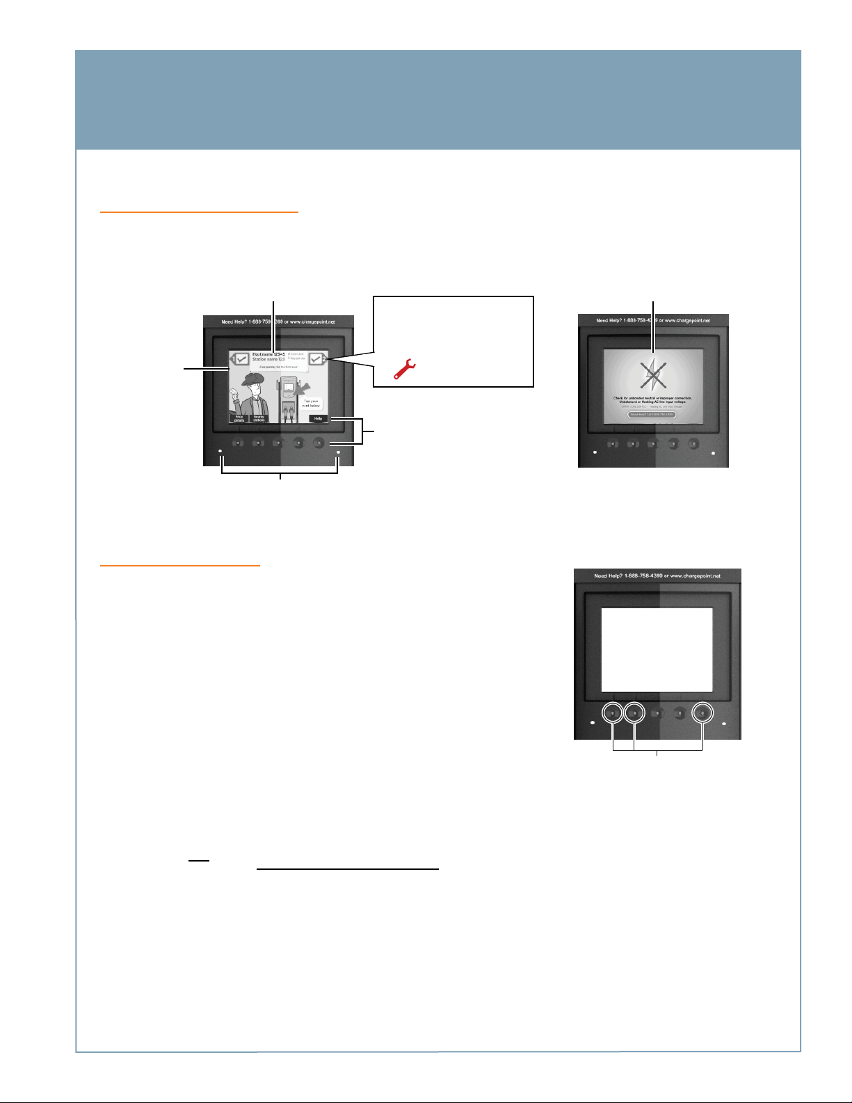
The CT4000’s display, and its associated error LEDs, alert you of several types of errors.
For some errors, this top
banner displays an error
message instead of station
information
Under normal
conditions, the
station displays
the instructional
video
For some errors, one or both
error LED(s) will appear solid or
blinking red
The status icon for each port
should display a green check
mark. If these icons appear, the
port (or station) has an error:
Choose a menu
option by pressing
the button below it
In some cases, a static error
message fills the entire display
Display Station Codes
Even if the station’s display and LEDs show no indication of an error, always
display the station codes to confirm that no errors exist. To display station codes:
1. Display the station’s Service Menu:
• if the station is not activated on ChargePoint, simultaneously press and
hold the two leftmost buttons and the rightmost button for two seconds
• if the station is activated on ChargePoint, scan your ChargePoint Service
card
2. Press the station button immediately below the “HELP” menu option.
3. Press the station button immediately below the “DOWN” menu option to
highlight “Station Codes”.
4. Press SELECT.
This port is
displaying a
station code
This port is not
displaying a
station code
Simultaneously press and hold
these three buttons for two
seconds to display the Service
Menu on an unactivated station
If you see a station code, you must resolve or report the error before leaving the installation site. Station codes are
described on the following pages.
6-1
Page 52
ChargePoint® Charging Stations
Description of Station Codes
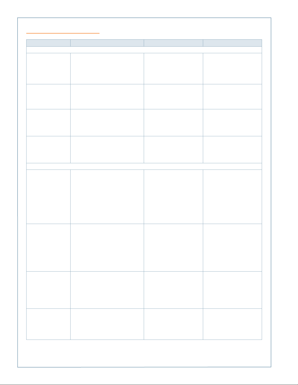
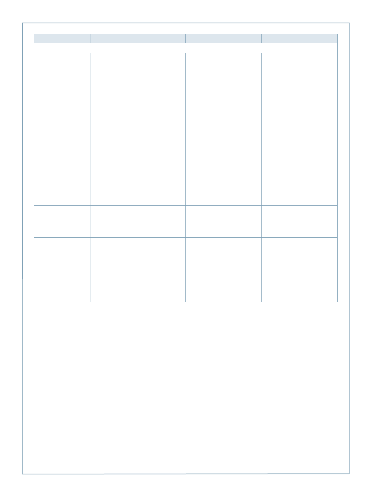
Code Symptom Possible cause(s) Recommended Action(s)
In most cases, a driver can resolve the following station codes that begin with the digit “1”:
101Over Current Detection
102Ventilation Requested
n = the number of the applicable port
n = the number of the applicable port
During charging, the vehicle
attempted to draw more power than
allowed. The station stops delivering
power to the vehicle.
Vehicle requires ventilated charging
which is not supported by the
station. The station stops delivering
power to the vehicle.
Can indicate faulty wiring in the
vehicle. End the session by inserting
the station’s plug back into its
holster, then restart the session.
If the error persists, call ChargePoint
Customer Support at 1-877-850-
4562.
Driver will be unable to use the
station to charge their type of
vehicle. Call the vehicle manufacturer.
103Soft Ground Fault
n = the number of the applicable port
104Immediate Ground Fault
n = the number of the applicable port
In most cases, an electrician can resolve the following station codes that begin with the digit “2”:
201-SIM
202-EF
203-SNP The banner between the port icons displays
“STATION NOT ACTIVATED ON CHARGEPOINT
- GRACE SESSIONS REMAINING (N).”
When all grace sessions have been used:
During charging, the station detected
a ground fault. The station stops
delivering power to the vehicle, but
continues to retry every 30 seconds.
On initial plug-in, the station
detected a ground fault. The station
stops delivering power to the vehicle.
SIM Not Detected - The SIM is either
not installed or is incorrectly installed
and the station can not communicate
with the ChargePoint network.
Earth Fault - The station has
detected a poor ground connection
and the station is not operational.
Station not activated - The station
can be used to charge for the
specified number of remaining grace
sessions. When all grace sessions
have been used, the station is not
operational.
End the session by inserting the
station’s plug back into its holster,
then restart the session.
If the error persists, call ChargePoint
Customer Support at 1-877-850-
4562.
End the charging session by inserting
the station’s plug back into its
holster, then restart the session.
If the error persists, call ChargePoint
Customer Support at 1-877-850-
4562.
Disconnect power and install (or
re-install) the SIM card as described
on page 5-4.
If the error persists, call ChargePoint
Customer Support at 1-877-850-
4562.
Disconnect power and check that
the station is properly grounded as
described on page 1-7. After ensuring
the station is properly grounded,
reconnect power.
If the error persists, try unplugging
the head assembly and plugging it
back in.
If the error continues to persist, call
ChargePoint Customer Support at
1-877-850-4562.
Arrange for the station to be
activated on ChargePoint by
completing the steps in Chapter 5.
204-NGNP Before activation:
6-2
The banner between the port icons displays
“NO GATEWAY WITHIN RANGE.”
After activation:
All you will see is the code listed on Help >
Station Codes.
Non-Gateway Not Paired - The
station is set up to communicate with
a gateway station that is either not
within range, or is not powered on.
Verify that the gateway station is
powered on and located within 150
feet line of sight (no obstructions).
If the error persists after these
requirements are met, call
ChargePoint Customer Support at
1-877-850-4562.
Page 53

Code Symptom Possible cause(s) Recommended Action(s)
205-UNS Before activation:
206-FLC Before activation:
The banner between the port icons displays
“NETWORK SIGNAL NOT DETECTED.”
After activation:
All you will see is the code listed on Help >
Station Codes.
After activation:
You will see the code listed on Help > Station
Codes and the port status icons will show:
n = the number of the applicable port
or
Unknown Network Signal - The
gateway station is unable to establish
a network connection on AT&T/
Verizon (US) or Rogers (Canada).
Floating Line Connection - The
voltage of an AC input line has fallen
below 80 volts AC relative to ground.
Even if the line to line voltage
measures nominally 208 or 240 volts,
the voltage of each line must be
greater than 80 volts when measured
to ground.
The two most common causes of a
Power Line Fault are:
• A poor connection in the wiring
supplying power and the ground
connection to the station. There
could be a poor connection
between the buss bar and circuit
breaker, the breaker to the branch
circuit feeding the station, or
at any splice along the branch
circuit.
• The station is connected to
an incompatible improperly
grounded power source. All power
and ground connections must
be clean and tight and carry the
full rated current of the station.
Do not connect the station to an
ungrounded (floating neutral)
system, a corner grounded Delta
system, or the high (or “stinger”
leg) of a center grounded Delta
system.
Ensure the station is receiving an
adequate signal strength from the
cellular network. To do so, display the
Service menu*, then:
• Check the network signal
for each type of modem by
choosing: Basic mode > Display
last measured RSSI. The strength
of the signal should be A, B,
or C.
• If the network signal is Grade
D, or if a better network signal
is available on the other type
of modem, change modems by
choosing: Basic mode > Change
modem technology (CDMA or
GSM).
If the signal strength is either
weak (D) or not available for both
CDMA and GSM, arrange for cellular
repeaters to be installed near the
installation site.
If the error persists when the station
shows a strong network signal, call
ChargePoint Customer Support at
1-877-850-4562.
*To display the station’s Service
Menu, scan your ChargePoint Service
card (if the station is activated) or, if
the station is not activated, press the
three station buttons as described on
page B-3.
Correct any faulty connections.
Verify that the station is connected
to a system with its neutral properly
grounded according to NEC Article
250.
Verify the station is connected to
one of the system types described in
Chapter 1.
If the error persists, call ChargePoint
Customer Support at 1-877-850-
4562.
Troubleshooting
6-3
Page 54
ChargePoint® Charging Stations
Code Symptom Possible cause(s) Recommended Action(s)
ChargePoint Support may need to resolve the following station codes that begin with the digit “3”:
301-BA
Breakaway Fault - The cable has
been removed from the station
or is damaged. The station is not
operational.
Call ChargePoint Customer Support
at 1-877-850-4562 to arrange to have
the station replaced.
302-GST
303-RSC
305-LCO
306-BF
n = the number of the applicable port
or
n = the number of the applicable port
or
GFCI Self Test Failed - The station
detected a ground fault during power
up and is not operational.
Relay Stuck Closed - When
attempting to end a charging session,
the relay stays closed. Although the
driver can return the station’s plug to
its holster, the station doesn’t end the
session. Therefore, a new session can
not be started.
Pilot Unreachable - The station is out
of service.
Boot Fault - The station is out of
service.
End the session by inserting the
station’s plug back into its holster,
then restart the session.
If the error persists, call ChargePoint
Customer Support at 1-877-850-
4562.
Call ChargePoint Customer Support
at 1-877-850-4562 to arrange to have
the station replaced or repaired.
Disconnect and reconnect power.
If the error persists, call ChargePoint
Customer Support at 1-877-8504562 to arrange to have the station
replaced or repaired.
Disconnect and reconnect power.
If the error persists, call ChargePoint
Customer Support at 1-877-8504562 to arrange to have the station
replaced or repaired.
307-HE
Hardware Error - The station is out
of service.
Disconnect and reconnect power.
If the error persists, call ChargePoint
Customer Support at 1-877-8504562 to arrange to have the station
replaced or repaired.
6-4
Page 55
Troubleshooting
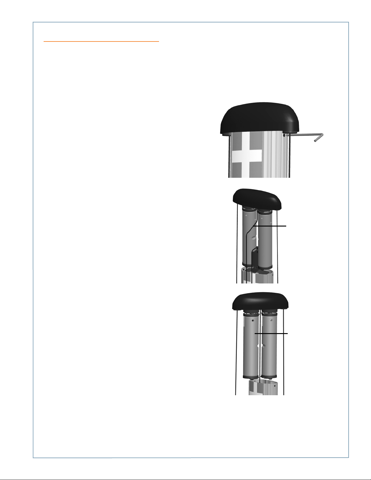
Charging Cable Doesn’t Move Freely
If the charging cable does not extend or retract fully and smoothly, it is likely that it’s rope has come off the pulley and you
must re-position it.
You will need:
T25 L-wrench
Follow these steps:
1. Using the T25 L-wrench, loosen the set screws on
each side of the retractor below the top cap.
2. Each rope is attached to a weight that sits on a shelf.
Pull the weight shelf up by pulling the rope located
in the middle of the top cap.
3. Rotate the top cap so the weight controlling the
rope that doesn’t move freely is facing towards you.
Pull the center rope to raise
the weight shelf
Rotate the top cap so the
faulty side faces towards
you
6-5
Page 56
ChargePoint® Charging Stations
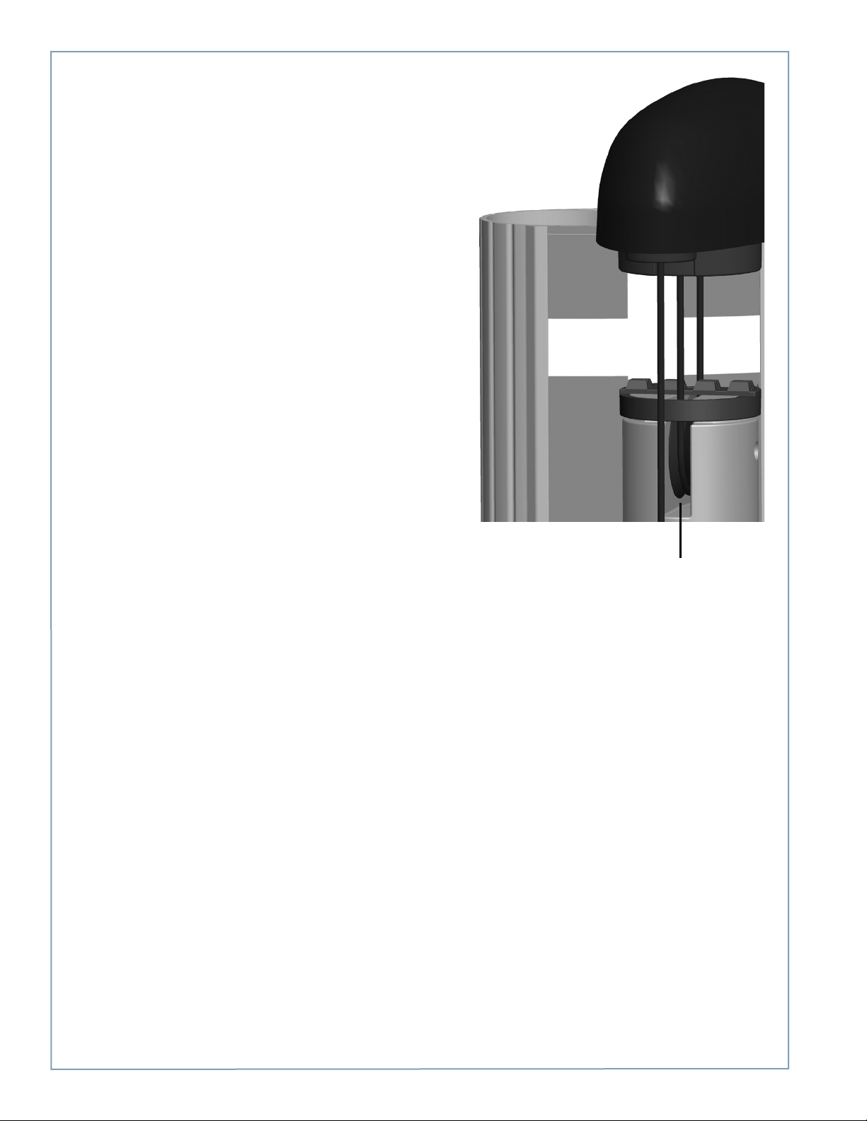
4. Inspect the rope to ensure it is properly aligned
onto the pulley.
5. Carefully lower the weight back into the retractor.
6. Rotate the top cap back into position and re-tighten
the set screws to about 10 in-lbs.
Ensure the rope is properly
aligned onto the pulley
6-6
Page 57
Preparing the Installation Site for a Bollard Mount
Before You Start
The ChargePoint® Charging Station’s bollard mount can be installed either:
• into the ground
• onto an existing concrete surface (on an intermediate floor only)
This appendix provides basic guidelines for preparing the installation site in both scenarios.
IMPORTANT: Always check local codes to ensure compliance. You may need to adjust the guidelines provided in this
appendix to comply with codes that apply at your installation location.
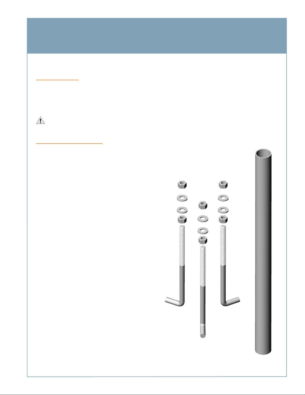
Installing Into the Ground
To install the CT4000’s bollard mount into the ground, you will
need:
• Concrete mix
• Three 5/8” galvanized J-Bolts at least 11 1/2” (29.2 cm)
long, with a minimum yield of proof strength of 80,000
psi (example bolt specification is F1554 Grade 105, red
painted end) with nuts and washers, as shown. Ensure
that J-Bolts, nuts, and washers are in compliance with all
applicable codes.
• Conduit at least 1 1/2” (38 mm) diameter. Ensure that
conduit is in compliance with all applicable codes.
• Base plate mounting template. This template is stapled
into the center fold of this document. A PDF version is
available at:
www.chargepoint.com/support-installation-guides.php
Ensure the PDF version is accurate by printing it at 100%
scale on 11” x 17” paper, and then verifying at least one
dimension.
A
A-1
Page 58
ChargePoint® Charging Stations
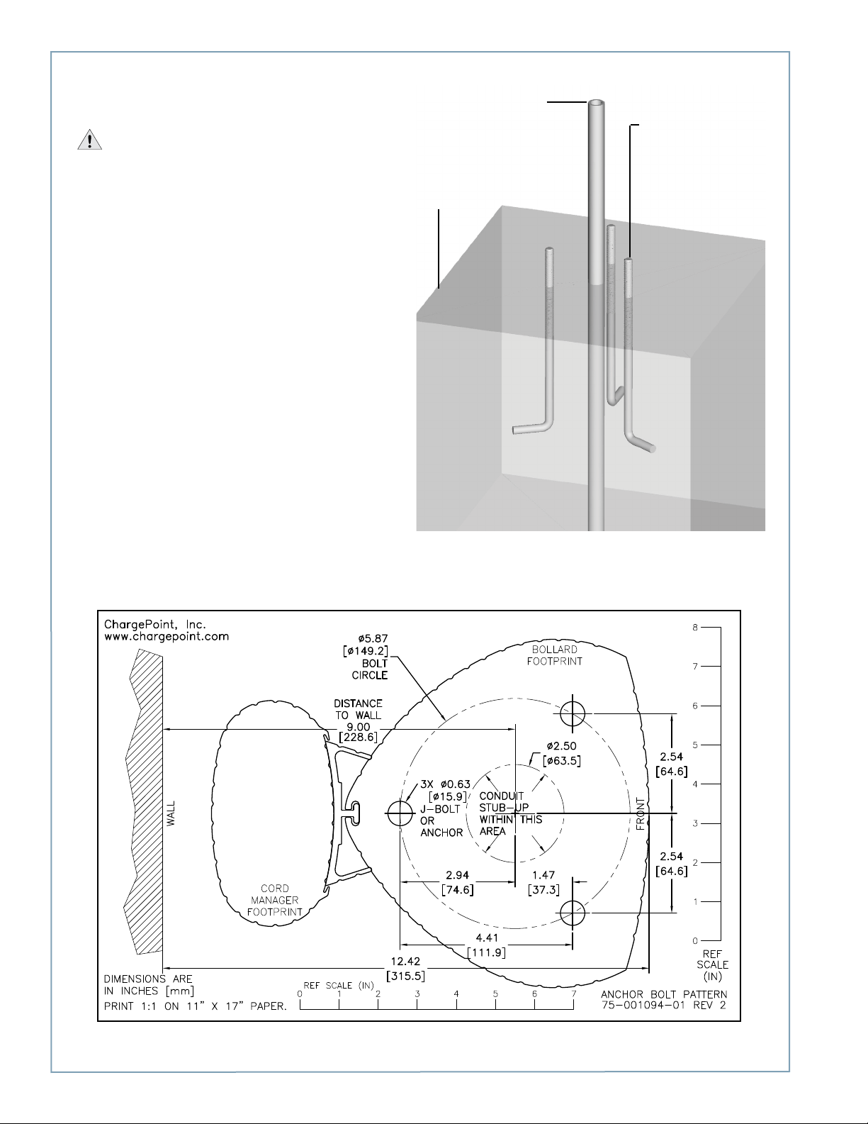
Install J-Bolts and conduit into concrete as illustrated. To
ensure correct alignment, use the template stapled into the
center fold of this document (illustrated below).
IMPORTANT:
• The concrete block must measure at least 24” (61 cm)
on all sides. Check local codes to ensure compliance.
• The J-Bolts threads must extend at least 2 ½” (6.4 cm)
above the concrete and 9” (23 cm) below the concrete.
• The conduit must extend 12” to 24” (30 to 61 cm)
above the concrete. Check local codes to ensure
compliance.
• You can also print a PDF version of the mounting
template, available at www.chargepoint.com/supportinstallation-guides.php. Before using a self-printed
template, print at full scale on 11” x 17” paper and verify
at least one dimension.
Conduit must extend
12-24” (30-61 cm) above
the concrete. Check local
codes.
Concrete block should
extend no more than 2”
(50 mm) above grade.
J-Bolts must extend at
least 2 ½” (6.4 cm)
above the concrete and
9” (23 cm) below the
concrete.
Example of template (not to scale):
A-2
Page 59
Installing Into Existing Concrete
IMPORTANT! Follow instructions exactly as described to ensure rated performance. Ensure compliance with all
applicable local and national electrical and building codes.
You will need:
• Three bolts at least 5/8” in diameter (length will vary depending on thickness of floor but must extend at least 2 ½”
above the concrete). Each bolt must be capable of supporting a minimum of 8,000 pounds (such as a 5/8” F1554
Grade 55).
• 1 1/16” hole saw, or a ¾” trade size Greenlee punch
• Masonry drill and drill bit
• Conduit sealing ring (or an alternative sealing method)
• Base plate mounting template (provided in the shipping box with the bollard)
Install the anchors
CAUTION: Use X-ray imaging to avoid drilling into any rebar, conduit, or pipe that may exist in the concrete.
Using the template provided in the bollard’s shipping box, drill the three anchor bolt holes at their correct locations.
TIP! Create a reusable plywood or plastic template using the bollard mount’s base plate (with the pipe) or the paper template
provided in the bollard’s shipping box.
Align the anchors and bolt to the garage floor. The bolts must protrude at least 2 ½” above the concrete.
Run conduit into bollard mount
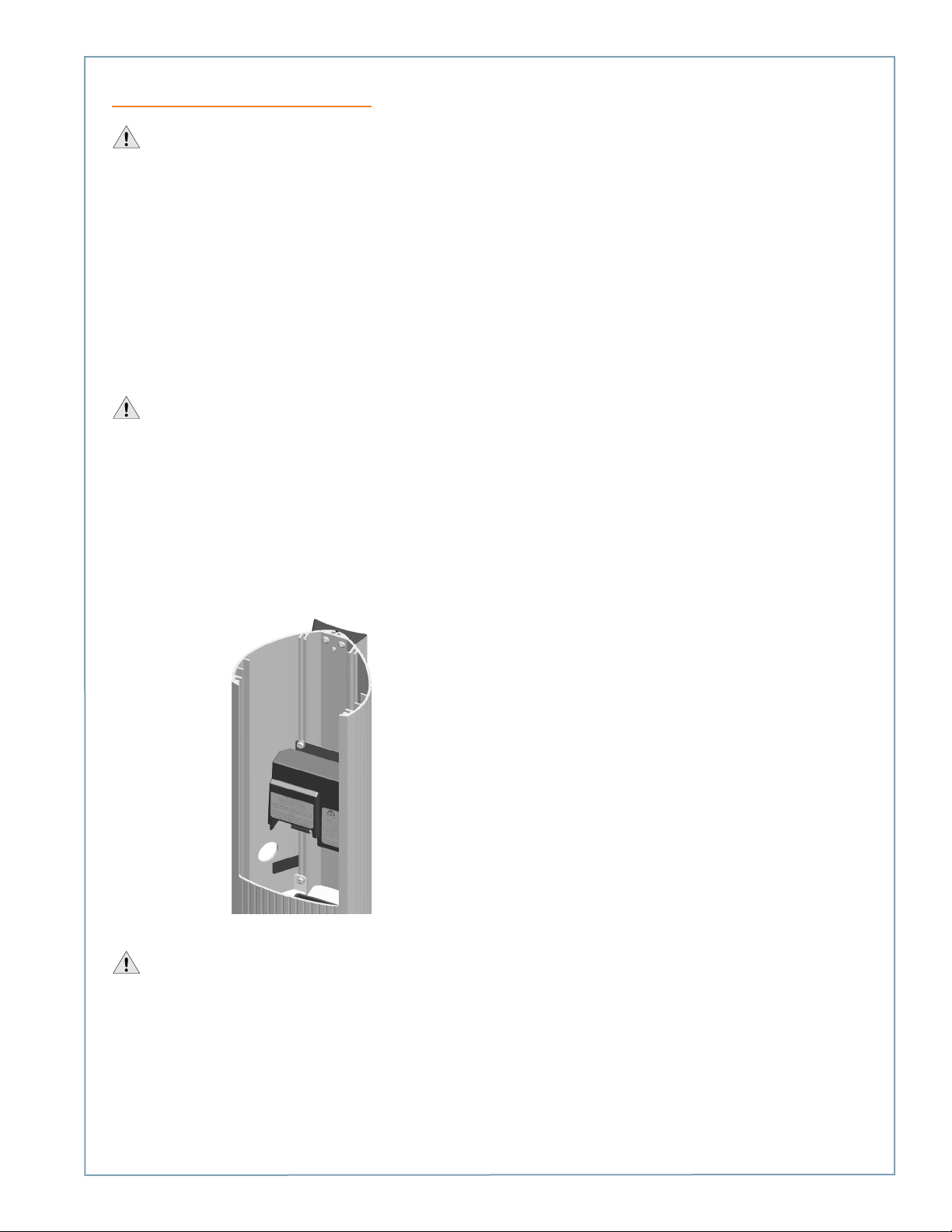
To run wiring into the bollard, use the hole saw or punch to cut an opening approximately half way up the bollard. The
opening should be located between 29” and 32” from the bottom of the bollard, immediately below the terminal block.
Seal the conduit, ensuring compliance with applicable electrical codes.
CAUTION: Protect the wiring that runs into the bollard to prevent them from contacting sharp edges.
A-3
Page 60

Page 61
B
Removing or Replacing the EV Charging Sign
The method used to remove and/or replace the EV Charging Sign differs depending on whether the station has been
installed. Both methods are described in this appendix.
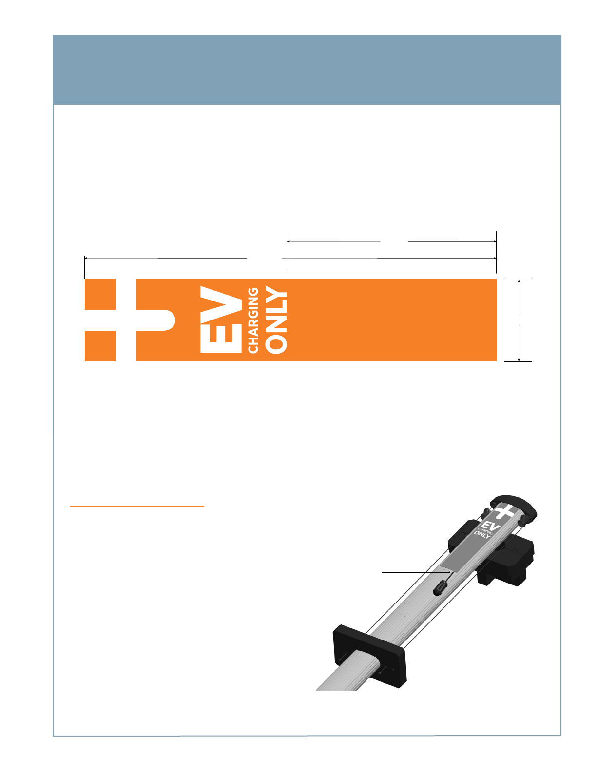
To ensure a proper fit, a replacement sign must have the following characteristics, at a minimum:
• Material - Vinyl with a maximum thickness of .03”
• Dimensions - Exactly 4.00” (102 mm) wide and up to 20.25” (514 mm) high
A detailed sign specification is available at www.chargepoint.com/support-installation-guides.php. Example of sign
specification (not to scale):
261 mm
(10.28”)
514 ± 1 mm
(20.25”)
102.5 ± 0.5 mm
(4.00”)
During Station Installation
1. After removing the retractor from the shipping box,
remove the existing sign before mounting it. Insert
your finger or a screwdriver underneath the bottom
edge of the sign to pull it out of the retractor’s
grooves.
2. To install a new sign, bend it slightly and insert it into
the grooves.
insert finger or
screwdriver to pull
existing sign out
of its grooves
B-1
Page 62
ChargePoint® Charging Stations
After Station Installation
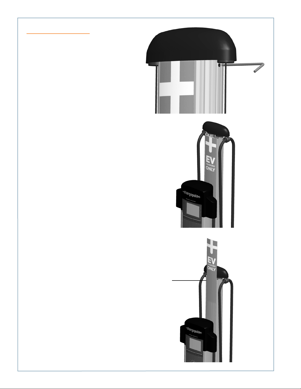
To remove the sign after the station has been installed:
1. Use a T25 L-wrench to loosen the set screw on
each side of the top cap, as shown.
2. Pull the top assembly up and move it towards the
back of the retractor.
3. Slide the existing sign out of the grooves.
To install a new sign:
1. Slide the replacement sign into the grooves by
bending is slightly. See the previous page for sign
specifications.
2. Re-install the top assembly. Remember to tighten
the set screws.
B-2
Bend the sign
slightly to insert it
into the grooves
Page 63

C
CT4000 Power Sharing Instructions
Jumpers (2) Electrical Rating label
A CT402X provides 30A of charging to each port when connected to two 40A circuits, or it can be configured to allow both
ports to share one 40A circuit. To allow both ports to be powered by a single 40A circuit, you must complete the steps
provided this appendix. You will need the supplied power sharing kit (CT4020-PSHARE), located in the shipping box with the
station’s main body. The power sharing kit contains:
Before you start
Before installing the power sharing kit, complete the installation instructions for the main body (see Chapter 1 or 2), but do
not connect the wiring.
Overview of steps
Installing the power sharing kit involves a few simple steps, summarized below and detailed in the remainder of this appendix:
1. Install the Jumpers (page C-2)
2. Connect the Wiring (page C-3)
3. Apply the Electrical Rating Label (page C-4)
4. Configure the Station for Power Sharing (page C-5)
C-1
Page 64
ChargePoint® Charging Stations
Step 1: Install the Jumpers
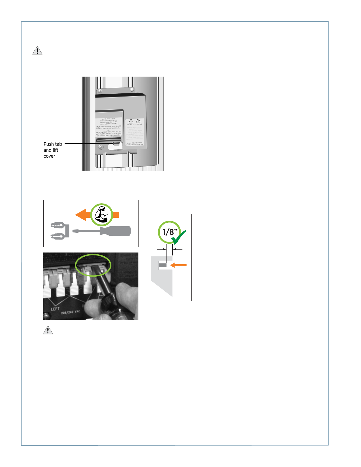
WARNING: Disconnect power before you begin.
• Push the black tab on the terminal block to release the terminal block cover, then slide the cover up until it locks into the
raised position:
• Insert the jumpers into the slots located near the upper edge of the terminal block. Using a large flat blade screwdriver,
push firmly on each jumper until you feel it lock into place.
IMPORTANT: Ensure both jumpers are fully seated. The jumpers should recede 1/8” (3 mm) below the outer
surface of the terminal block, as shown. If they are flush, they are not fully inserted.
C-2
Page 65
1/2” (13 mm)
Step 2: Connect the Wiring
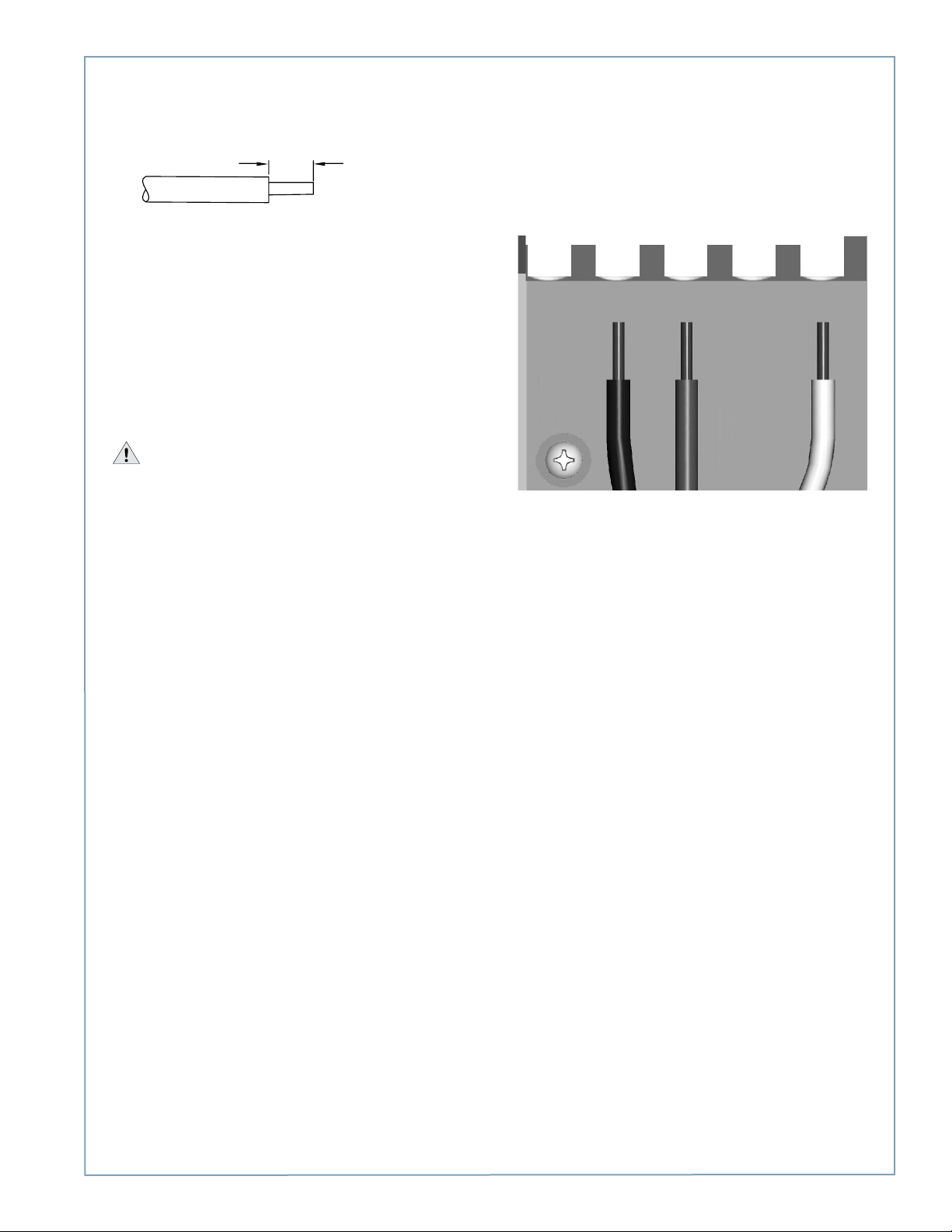
• Strip wires ½” (13 mm).
• Lift the white lever on the terminal block that
corresponds with the ground connection (center), insert
the ground wire, then push the lever down until it clicks
into its fully closed position.
• Lift the white levers on the terminal block that
corresponds with the RIGHT port’s L1 and L2
connections. Insert the L1 and L2 wires fully into the
terminal block, then push the levers down until they click
into their fully closed positions.
NOTE: The connections for the left port are not used.
Power for the left port is carried through the jumpers.
WARNINGS:
• Use copper conductors only.
• Do NOT provide GFCI protection at panel. The CT4000
has built-in GFCI protection.
• In areas with frequent thunder storms, add surge
protection at the service panel for all circuits.
• Use new circuit breakers only. Used breakers can damage
equipment and introduce the potential for an electrical
fire.
• Ensure all power and ground connections, especially
those at the breaker and buss bar, are clean and tight.
Remove all oxide from all conductors and terminals
before connecting wiring.
LEFT
L1
RIGHT
L1
GND
LEFT
L2
RIGHT
L2
C-3
Page 66
ChargePoint® Charging Stations
Step 3: Apply the Electric Rating Label
Apply the supplied Electrical Rating label to the left side of
the terminal block cover, just above the terminal block.
NOTE: Leave the cover in the raised position to facilitate
connection of the head assembly.
Electrical Rating
label
You are now ready to install the head assembly and top cap as described in Chapter 5.
IMPORTANT: When you finish installing the station, you must manually configure the station’s software for power
sharing, as described on the next page. Otherwise, the circuit breaker will trip when both charging ports are used.
C-4
Page 67
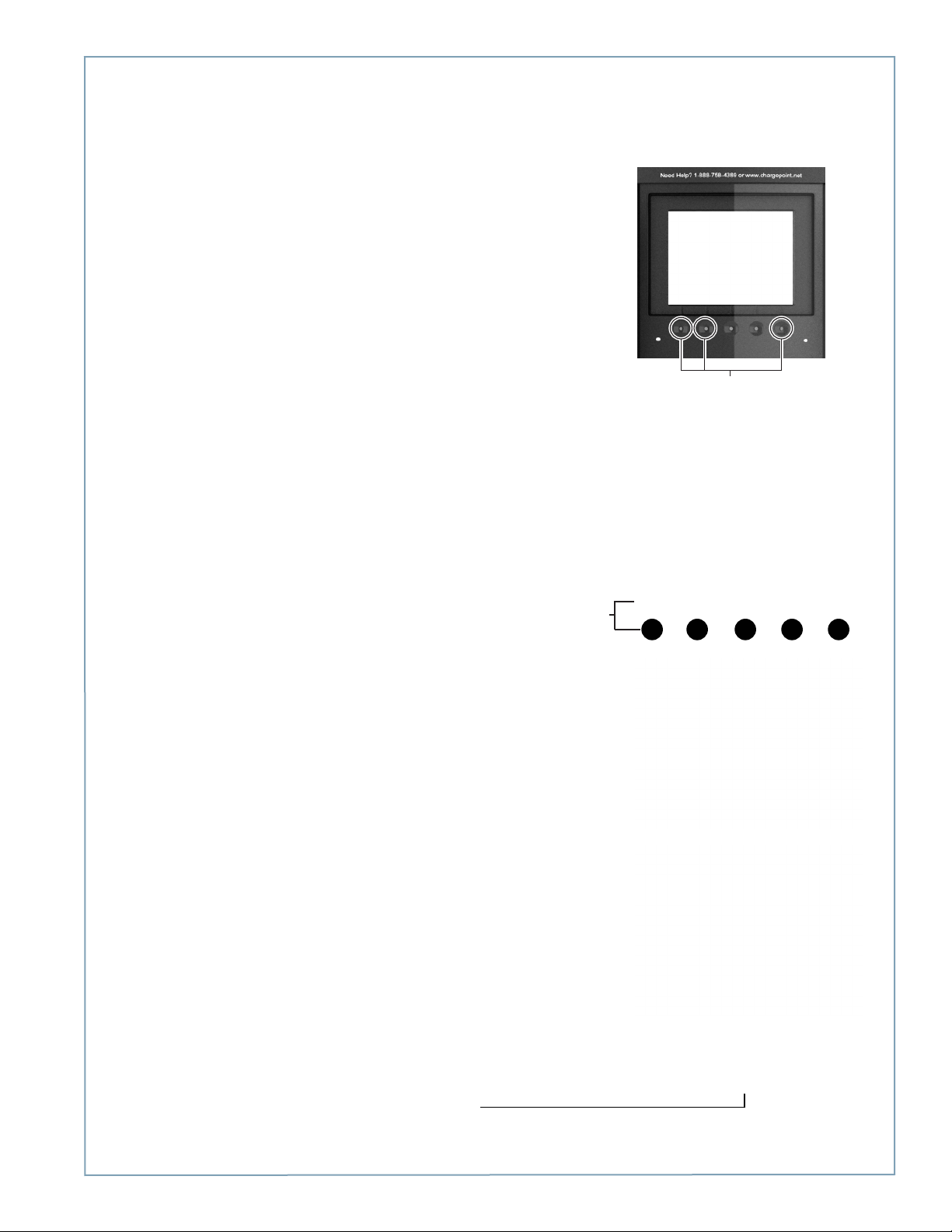
Step 4: Configure the Station for Power Sharing
Follow these steps to allow the station to be powered by a single circuit:
1. Display the station’s Service Menu:
• If the station is not activated on ChargePoint,
simultaneously press and hold the two leftmost
buttons and the rightmost button for two seconds.
• If the station has been activated, scan your
ChargePoint Service card
2. Select Basic mode.
Simultaneously press and hold
these three buttons for two
seconds to display the Service
3. Select Power Sharing Configuration.
4. Select Enable.
Press the button
immediately below
the menu item to
choose the
associated function
5. Select Exit to leave the Service Menu.
6. Confirm that the station’s display
indicates that power sharing has been
configured.
The station
indicates that
power sharing
is configured
C-5
Page 68

Page 69

D
Limited Product Warranty
This Limited Product Warranty applies to you, a customer who has purchased CHARGEPOINT’s Charging Stations and/or
related products (“Products”) from CHARGEPOINT, INC., or one of its authorized distributors and not for resale.
LIMITED ONE-YEAR WARRANTY: Subject to the exclusions from warranty coverage set forth below, CHARGEPOINT warrants
that the Product will be free from any defects in materials and/or workmanship (the “Limited Warranty”) for a period of
one (1) year after the date of the initial installation of the Product (the “One-Year Warranty Period”). If the Product becomes
defective in breach of the Limited Warranty, CHARGEPOINT will, upon written notice of the defect received during the OneYear Warranty period, either repair or replace, at ChargePoint’s election, the Product if it proves to be defective; provided,
that CHARGEPOINT will not be responsible for the cost of any labor associated with the repair or replacement of any
defective Product.
TWO-, THREE-, FOUR- OR FIVE-YEAR EXTENDED WARRANTY (Additional Charge Applies): Subject to the exclusions from
warranty coverage set forth below, if you have purchased an extended warranty, and if the Product becomes defective in
breach of the Limited Warranty above at any time during the extended warranty period after the date of the initial installation
of the Product, CHARGEPOINT will, upon written notice of the defect received during the extended warranty period, either
repair, provide replacement parts for the defective parts of the Product or replace the Product, at ChargePoint’s election, if
it proves to be defective; provided, that CHARGEPOINT will not be responsible for the cost of any labor associated with the
repair or replacement of any defective Product.
CHARGEPOINT’s Options: You acknowledge that replacement products provided by CHARGEPOINT under each of the
Limited Warranty and the Extended Warranty may be re-manufactured or reconditioned Products or, if the exact Product is
no longer manufactured by CHARGEPOINT, a Product with substantially similar functionality (“Replacement Products”). Any
Replacement Products so furnished will be warranted for the remainder of the original Warranty Period or ninety (90) days
from the date of delivery of such Replacement Product, whichever is greater. Should CHARGEPOINT be unable to repair or
replace the Product, CHARGEPOINT will refund the purchase price of the Product.
EXCLUSIONS FROM LIMITED WARRANTY AND EXTENDED WARRANTY
IMPORTANT: The Limited Warranty and, if purchased, the Extended Warranty on your Product shall not apply to defects, or
service repairs, resulting from any of the following:
• Alteration or modification of the Product in any way not approved in writing by CHARGEPOINT.
• Vandalism.
• Abuse, damage or otherwise being subjected to problems caused by negligence (including but not limited to physical
damage from being struck by a vehicle) or misapplication, or use of the Products other than as specified in the
applicable CHARGEPOINT documentation.
• Installation or relocation of the Products unless performed by CHARGEPOINT or by a ChargePoint authorized installer or
service provider.
• Improper site preparation or maintenance.
• Damage as a result of accidents, extreme power surge, extreme electromagnetic field, acts of nature or other causes
beyond the control of CHARGEPOINT.
• Use of the Product with software, interfacing, parts or supplies not supplied by CHARGEPOINT.
You are responsible for the proper installation and maintenance of the Product. Any service or repairs beyond the scope of
the Limited Warranty or the Extended Warranty above are subject to CHARGEPOINT’s then prevailing current labor rates and
other applicable charges.
Third Party Products. The Limited Warranty and Extended Warranty are exclusive of products manufactured by third parties
(“Third Party Products”). If such third party manufacturer provides a separate warranty with respect to the Third Party
Product, CHARGEPOINT will include such warranty in the packaging of the CHARGEPOINT Product.
OBTAINING WARRANTY SERVICE
To obtain warranty service you must: (a) obtain a return materials authorization number (“RMA#”) from CHARGEPOINT by
contacting 1-877-370-3802 (or for customers outside the U.S., contact 408-370-3802) and ask for Customer Service, and (b)
deliver the Product, in accordance with the instructions provided by CHARGEPOINT, along with proof of purchase in the form
of a copy of the bill of sale including the Product’s serial number, contact information, RMA# and detailed description of the
D-1
Page 70

ChargePoint® Charging Stations
defect, in either its original package or packaging providing the Product with a degree of protection equivalent to that of the
original packaging, to CHARGEPOINT at the address below. You agree to obtain adequate insurance to cover loss or damage
to the Product during shipment.
If you obtain an RMA# and return the defective Product as described above, CHARGEPOINT will pay the cost of returning the
Product to CHARGEPOINT. Otherwise, you agree to bear such cost, and prior to receipt by CHARGEPOINT, you assume risk of
any loss or damage to the Product. CHARGEPOINT is responsible for the cost of return shipment to you if the CHARGEPOINT
Product is found to be defective.
Returned products which are found by CHARGEPOINT to be not defective, returned out-of-warranty or otherwise ineligible
for warranty service will be repaired or replaced at CHARGEPOINT’s standard charges and shipped back to you at your
expense.
At CHARGEPOINT’s sole option, CHARGEPOINT may perform repair service on the Product at your facility, and you agree to
provide CHARGEPOINT with all reasonable access to such facility and the Product, as required. On-site repair service is not
available outside the United States.
All replaced parts, whether under warranty or not, are the property of CHARGEPOINT.
WARRANTY LIMITATIONS
THE LIMITED WARRANTY SET FORTH ABOVE IS EXCLUSIVE AND NO OTHER WARRANTY, WHETHER WRITTEN OR
ORAL, IS EXPRESSED OR IMPLIED BY CHARGEPOINT, TO THE MAXIMUM EXTENT PERMITTED BY LAW. THERE ARE NO
OTHER WARRANTIES RESPECTING THE PRODUCT AND DOCUMENTATION AND SERVICES PROVIDED UNDER THIS
AGREEMENT, INCLUDING WITHOUT LIMITATION ANY WARRANTY OF DESIGN, MERCHANTABILITY, FITNESS FOR A
PARTICULAR PURPOSE (EVEN IF CHARGEPOINT OR DISTRIBUTOR HAS BEEN INFORMED OF SUCH PURPOSE) OR AGAINST
INFRINGEMENT.
Some states or jurisdictions do not allow the exclusion of express or implied warranties so the above exclusions may not
apply to you. IF ANY IMPLIED WARRANTY CANNOT BE DISCLAIMED UNDER APPLICABLE LAW, THEN SUCH IMPLIED
WARRANTY SHALL BE LIMITED IN DURATION TO THE LIMITED WARRANTY PERIOD DESCRIBED ABOVE. NO WARRANTIES
APPLY AFTER THE TOTAL WARRANTY PERIOD. Some states or jurisdictions do not allow limitations on how long an implied
warranty lasts, so the above limitation may not apply to you.
NO AGENT OF CHARGEPOINT IS AUTHORIZED TO ALTER OR EXCEED THE WARRANTY OBLIGATIONS OF CHARGEPOINT.
CHARGEPOINT SPECIFICALLY DOES NOT WARRANT THAT ANY SOFTWARE WILL BE ERROR FREE OR OPERATE WITHOUT
INTERRUPTION.
THE REMEDIES IN THIS LIMITED PRODUCT WARRANTY ARE YOUR SOLE AND EXCLUSIVE REMEDIES.
LIMITATIONS OF LIABILITY
You acknowledge and agree that the consideration which you paid to CHARGEPOINT or one of its authorized distributors
does not include any consideration by CHARGEPOINT or one of its authorized distributors of the risk of consequential,
indirect or incidental damages which may arise in connection with your use of, or inability to use, the Product. THUS,
CHARGEPOINT OR ONE OF ITS AUTHORIZED DISTRIBUTORS WILL NOT BE LIABLE FOR ANY INDIRECT, INCIDENTAL,
SPECIAL, PUNITIVE OR CONSEQUENTIAL DAMAGES, INCLUDING WITHOUT LIMITATION LOST PROFITS, LOST BUSINESS,
LOST DATA, LOSS OF USE, OR COST OF COVER INCURRED BY YOU ARISING OUT OF OR RELATED TO YOUR PURCHASE
OR USE OF, OR INABILITY TO USE, THIS PRODUCT OR THE SERVICES, UNDER ANY THEORY OF LIABILITY, WHETHER IN
AN ACTION IN CONTRACT, STRICT LIABILITY, TORT (INCLUDING NEGLIGENCE) OR OTHER LEGAL OR EQUITABLE THEORY,
EVEN IF C CHARGEPOINT KNEW OR SHOULD HAVE KNOWN OF THE POSSIBILITY OF SUCH DAMAGES. IN ANY EVENT, THE
CUMULATIVE LIABILITY OF CHARGEPOINT OR ONE OF ITS AUTHORIZED DISTRIBUTORS FOR ALL CLAIMS WHATSOEVER
RELATED TO THIS PRODUCT OR THE SERVICE WILL NOT EXCEED THE PRICE YOU PAID FOR THIS PRODUCT.
THE LIMITATIONS SET FORTH HEREIN ARE INTENDED TO LIMIT THE LIABILITY OF CHARGEPOINT AND SHALL APPLY
NOTWITHSTANDING ANY FAILURE OF ESSENTIAL PURPOSE OF ANY LIMITED REMEDY.
Some states or jurisdictions do not allow the exclusion or limitation of incidental or consequential damages, so the above
limitation or exclusion may not apply to you.
THIS LIMITED PRODUCT WARRANTY GIVES YOU SPECIFIC LEGAL RIGHTS AND YOU MAY ALSO HAVE OTHER RIGHTS
WHICH VARY FROM STATE TO STATE OR JURISDICTION TO JURISDICTION.
D-2
Page 71

ADDITIONAL INFORMATION
This Limited Product Warranty is valid for U.S.A. and Canada only.
This Limited Product Warranty shall be governed by and construed in accordance with the laws of the State of California,
U.S.A., exclusive of its conflict of laws principles. The U.N. Convention on Contracts for the International Sale of Goods shall
not apply.
This Limited Product Warranty is the entire and exclusive agreement between you and CHARGEPOINT with respect to its
subject matter, and any modification or waiver of any provision of this statement is not effective unless expressly set forth in
writing by an authorized representative of CHARGEPOINT.
The Limited Product Warranty is not transferable by you to anyone else.
All inquiries or claims made under this Limited Product Warranty must be sent to CHARGEPOINT’s address as follows:
ChargePoint, Inc.
1692 Dell Avenue
Campbell, California 95008-6901
Tel: 408-370-3802
Fax: 408-370-3847
Email: [email protected]
D-3
Page 72

Page 73

Page 74

Campbell, CA 95008-6901 USA
1692 Dell Ave.
US toll free: +1-877-370-3802
www.chargepoint.com
 Loading...